


INSTALLATION AND OPERATION INSTRUCTIONS
CUSTOM BACK BAR CABINETS – SELF CONTAINED AND REMOTE
C US
US
MODELS
BR Series
BS Series
BR72
BS84
IMPORTANT INFORMATION
To register your product, visit our web site at (www.perlick.com). Click on “Commercial”, then “Service”. You will see the link to “Warranty Registration Form”. You must complete and submit this form or the installation date will revert back to the ship Date.
This manual has been prepared to assist you in the installation of your Cabinet and to acquaint you with its operation and maintenance.
We dedicate considerable time to ensure that our products provide the highest level of customer satisfaction. If service is required, your dealer can provide you with a list of qualified service agents. For your own protection, never return merchandise for credit without our approval.
We thank you for selecting a Perlick product and assure you of our continuing interest in your satisfaction.
WARNING: When lifting, the full weight of the cabinet must be supported. Lift from the cabinet base and not from the top. Improper lifting can result in severe damage to the cabinet.
Table of Contents |
|
PREPARING THE CABINET |
|
List of Included Parts................................................................ |
2 |
Tools Required............................................................................ |
2 |
Plumbing....................................................................................... |
2 |
Electrical........................................................................................ |
2 |
Uncrating and Inspection....................................................... |
2 |
Placing the Cabinet................................................................... |
2 |
Leveling the Cabinet................................................................. |
2 |
Installing Casters or Legs ....................................................... |
2 |
Installing the Base Plate.......................................................... |
2 |
Refrigeration and Temperature Control............................ |
3 |
Cleaning the Cabinet................................................................ |
3 |
Cleaning the Condenser......................................................... |
3 |
Stainless Steel Care Guide.................................................. |
4/5 |
Replacement Parts..................................................................... |
6 |
Reversing Door Swing.............................................................. |
7 |
Cleaning Stainless Steel........................................................... |
7 |
Wiring Diagram (BS Series)..................................................... |
8 |
Wiring Diagram (BR Series).................................................... |
9 |
|
Form No. Z2278 |
|
Rev. 10.04.10 |
8300 West Good Hope Road • Milwaukee,WI 53223 • Phone 414.353.7060 • Fax 414.353.7069 Toll Free 800.558.5592 • E-Mail perlick@perlick.com • www.perlick.com
SYSTEMS AND PRODUCTS FOR THE FOOD SERVICE AND BEVERAGE INDUSTRIES SINCE 1917
GENERAL INFORMATION – Custom Back Bar Cabinets
Parts List
•(3) Shelves per door (one may be used as a floor rack)
•Shelf clips
Tools Required
•#2 Phillips Screwdriver
•10” Cresent Wrench
•9/16” Allen Wrench
•5/16” and 3/8” Hex Socket
•Power Drill or Driver (for leg caster installation)
Plumbing
Push the cabinet into place using rollers when necessary. IMPORTANT: Proper air flow around the condensing unit is necessary for efficient operation. Never obstruct the air flow in and out of the condensing unit.
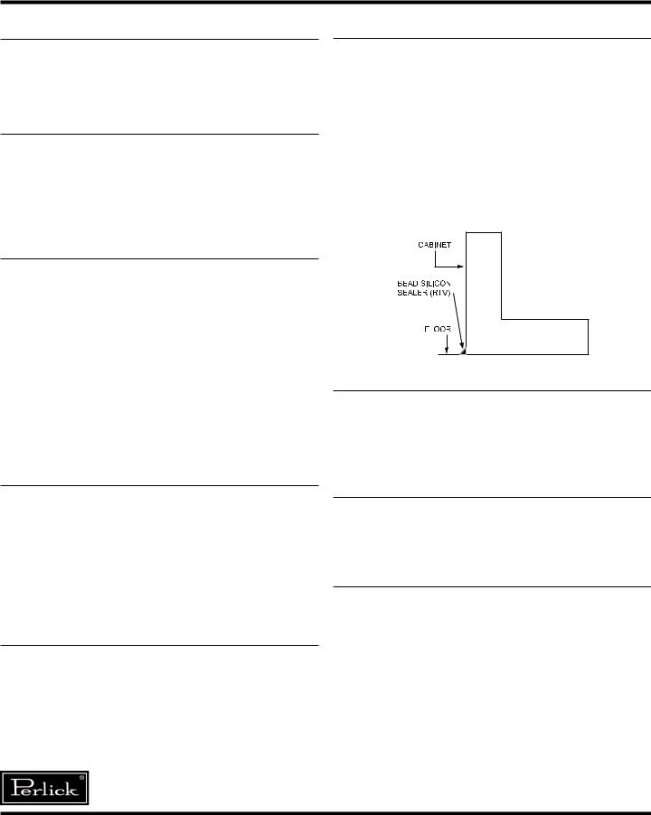
For sanitation purposes, it may be necessary to seal the base of the cabinet to the floor. This can be accomplished by laying a bead of silicone sealant between the base of the cabinet and the floor as shown by the figure below:
Plumbing
Condensate from the cooling coil is automatically evaporated through a condensate pan located in the condensing unit housing. Each unit is also equipped with a floor drain located in the right rear corner of the cabinet. The drain can be plumbed to an external floor drain by connecting to the 3/4” NPT thread out the side or the 1” NPS thread out the bottom. Both drains ports come plugged from the factory and can be removed if needed.
NOTE: Remote units require evaporator condensate to be plumbed to an external drain.
Electrical
The cabinet must be connected to a separately fused power source (see electrical specification plate) and grounded in accordance with National and Local Electrical Codes. Caution: Do not attempt to operate the equipment on any other power source than that listed on the Electrical Specification plate.
Uncrating and Inspection
Remove all crating material before operating. Carefully inspect cabinet for hidden damage. If damage is discovered, file your claim immediately with the transportation company. Perlick isnot responsible for damage in transit.
Leveling the Cabinet
When the cabinet is in place, check installation with carpenter’s level. When level front to back and left to right, accumulated water will drain out of the cabinet evaporator drain.
Installing Casters or Legs (optional)
Attach casters or legs to cabinet bottom in holes provided. Use the supplied 1/4”-20 x 3/4” hex head self-tapping machine screws.
Installing Base Plate (optional)
Attach brackets to cabinet bottom in holes provided. Attach base plate to brackets (see separate instructions, provided with kit). When returning cabinet to upright position, be careful not to bend brackets.
WARNING! To avoid compressor damage, after running cabinet in an upright position, let unit stand for 24 hours before plugging in and running the unit.
Perlick is committed to continuous improvement. Therefore, we reserve the right to change specifications without prior notice
Form No.Z2278 |
2 |
Rev. 10.04.10 |
GENERAL INFORMATION – Custom Back Bar Cabinets
Refrigeration and Temperature Control
Self-contained units are equipped with a heavy-duty refrigeration system that is factory set to maintain a product storage temperature of approximately 38° F.
Adjusting the Temperature
The temperature control is inside the cabinet on the left-hand side of the evaporator fan panel assembly. You will need a screwdriver to turn the adjusting screw. Make small adjustments until the desired temperature is achieved.
Colder Temperatures:
Turn the adjusting screw clockwise (to the right)
Warmer Temperatures:
Turn the adjusting screw counterclockwise (to the left).
Temperature Control ‘OFF’:
Turn the adjusting screw completely counterclockwise to the ‘O’ position until a click is noted.
The condenser fan motor turns off and on with the compressor. The evaporator fan motor is on all the time.
NOTE: Cabinet temperatures lower than 34° F will not allow for proper defrosting of the evaporator coil. If defrosting is necessary, turn the control knob to the OFF position until coil is defrosted.
Cleaning the Cabinet
Use a mild detergent and water to clean the inside and outside of the cabinet. Dry thoroughly. Never use a scouring pad or abrasive cleanser.
NOTE: An industrial strength, commercial cleaner can be used to clean the outside of painted cabinets.
Cleaning the Condenser
The condenser (located behind the front grille cover) should be inspected every 30 days and cleaned, if necessary. Use a long handled, stiff brush to clean the dirt from the front surface of the condenser. Keeping the condenser free from dust and dirt will ensure efficient operation.
CAUTION: Do not bend the fins while brushing the front of the condenser.
Failure to keep the condenser clean will cause a loss in condensing unit efficiency.
Perlick is committed to continuous improvement. Therefore, we reserve the right to change specifications without prior notice
3 |
Form No.Z2278 |
Rev. 10.04.2010 |
 Loading...