

Ultrasonic sensor UB120-12GM-I-V1
Technical data
General specifications
Sensing range 15 ... 120 mm
Adjustment range 20 ... 120 mm
Dead band 0 ... 15 mm
Standard target plate 10 mm x 10 mm
Transducer frequency approx. 850 kHz
Response delay approx. 27 ms
Indicators/operating means
Model Number
UB120-12GM-I-V1
Single head system
Features
• Extremely narrow projection cone
•Analog output 4mA...20mA
• Very small unusable area
• Measuring window adjustable
• Short response time
Diagrams
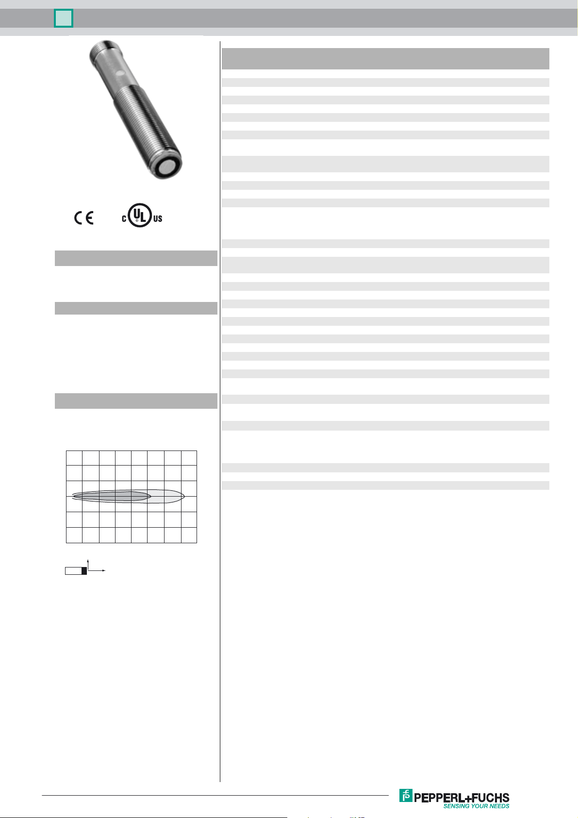
Characteristic response curve
Distance Y [mm]
75
50
25
1
0
-25
-50
-75
0 25 50 75 100 125 150 175 200
Y
Curve 1: flat surface 10 mm x 10 mm
Curve 2: round bar, Ø 8 mm
2
Distance X [mm]
X
LED yellow solid yellow: object in the evaluation range
LED red solid red: Error
Electrical specifications
Operating voltage U
No-load supply current I
Input
Input type 1 program input
Output
Output type 1 analog output 4 ... 20 mA
Resolution 0.17 mm
Deviation of the characteristic curve ± 1 % of full-scale value
Repeat accuracy ± 0.5 % of full-scale value
Load impedance 0 ... 300 Ohm
Temperature influence ± 1.5 % of full-scale value
Ambient conditions
Ambient temperature -25 ... 70 °C (-13 ... 158 °F)
Storage temperature -40 ... 85 °C (-40 ... 185 °F)
Mechanical specifications
Connection type Connector M12 x 1 , 4-pin
Degree of protection IP67
Material
Housing brass, nickel-plated
Transducer epoxy resin/hollow glass sphere mixture; foam polyurethane,
Mass 25 g
Compliance with standards and
directives
Standard conformity
Standards EN 60947-5-2:2007+A1:2012
Approvals and certificates
UL approval cULus Listed, Class 2 Power Source
CCC approval CCC approval / marking not required for products rated ≤36 V
B
0
yellow, flashing: program function, object detected
red, flashing: program function, object not detected
10 ... 30 V DC , ripple 10 %
≤ 30 mA
lower evaluation limit A1: -U
A2: +4 V ... +U
input impedance: > 4.7 kΩ, pulse duration: ≥ 1 s
cover PBT
IEC 60947-5-2:2007 + A1:2012
EN 60947-5-7:2003
IEC 60947-5-7:2003
B
SS
... +1 V, upper evaluation limit
B
Release date: 2017-07-12 08:57 Date of issue: 2017-07-12 188175_eng.xml
Refer to “General Notes Relating to Pepperl+Fuchs Product Information”.
1
Ultrasonic sensor UB120-12GM-I-V1
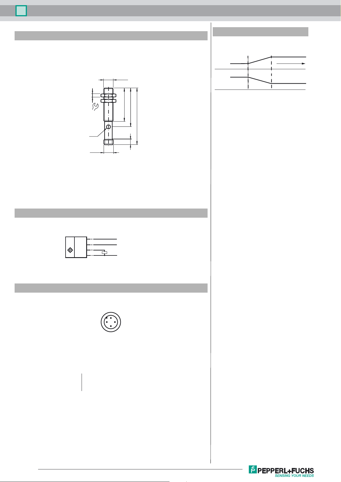
Dimensions
4
17
(Torque)
max. 10 Nm
LED
M12x1
M12x1
41
48.4
6
Additional Information
Programming the analog output mode
Rising ramp
A1 < A2:
Falling ramp
A2 < A1:
70
A1
A2
object range
A2
A1
Electrical Connection
Standard symbol/Connections:
(version I)
U
Core colors in accordance with EN 60947-5-2.
Pinout
Wire colors in accordance with EN 60947-5-2
1 BN
2 WH
3 BU
4 BK
1 (BN)
2 (WH)
4 (BK)
3 (BU)
2
1
3
(brown)
(white)
(blue)
(black)
+ U
B
Teach input
Analog output
- U
B
4
Release date: 2017-07-12 08:57 Date of issue: 2017-07-12 188175_eng.xml
Refer to “General Notes Relating to Pepperl+Fuchs Product Information”.
2

Ultrasonic sensor UB120-12GM-I-V1
Accessories
UB-PROG2
Programming unit
BF 5-30
Universal mounting bracket for cylindrical sensors with a diameter of 5 ... 30 mm
BF 12
Mounting flange, 12 mm
BF 12-F
Mounting flange with dead stop, 12 mm
V1-G-2M-PVC
Female cordset, M12, 4-pin, PVC cable
V1-W-2M-PUR
Female cordset, M12, 4-pin, PUR cable
UVW90-M12
Ultrasonic -deflector
Adjusting the evaluation limits
The ultrasonic sensor features an analogue output with two teachable evaluation limits. These are set by applying the supply
voltage -U
indicate whether the sensor has recognised the target during the TEACH-IN procedure. The lower evaluation limit A1 is taught
with -U
Two different output functions can be set:
1. Analogue value increases with rising distance to object (rising ramp)
2. Analogue value falls with rising distance to object (falling ramp)
TEACH-IN rising ramp (A2 > A1)
- Position object at lower evaluation limit
- TEACH-IN lower limit A1 with - U
- Position object at upper evaluation limit
- TEACH-IN upper limit A2 with + U
TEACH-IN falling ramp (A1 > A2):
- Position object at lower evaluation limit
- TEACH-IN lower limit A2 with + U
- Position object at upper evaluation limit
- TEACH-IN upper limit A1 with - U
Default setting
A1: unusable area
A2: nominal sensing range
Mode of operation: rising ramp
LED Displays
or +UB to the TEACH-IN input. The supply voltage must be applied to the TEACH-IN input for at least 1 s. LEDs
B
, A2 with +UB.
B
B
B
B
B
Displays in dependence on operating mode Red LED Yellow LED
TEACH-IN evaluation limit
Object detected
No object detected
Object uncertain (TEACH-IN invalid)
off
flashes
on
flashes
off
off
Normal mode (evaluation range) off on
Fault on previous state
Installation conditions
If the sensor is installed at places, where the environment temperature can fall below 0 °C, for the sensors fixation, one of the
mounting flanges BF 12, BF 12-F or BF 5-30 must be used. In case of direct mounting of the sensor in a through hole, it has to be
fixed at the middle of the housing thread.
Release date: 2017-07-12 08:57 Date of issue: 2017-07-12 188175_eng.xml
Refer to “General Notes Relating to Pepperl+Fuchs Product Information”.
3
 Loading...