

Page 1
PENTAX Industrial Instruments Co.,Ltd.
2-36-9, Maeno-cho
Itabashi-ku, Tokyo 174-0063 Japan
Tel. +81 3 3960 0502
Fax +81 3 3960 0509
E-mail: international@piic.pentax.co.jp
Website:www.pentax.co.jp/piic/survey
www.pentaxsurveying.com
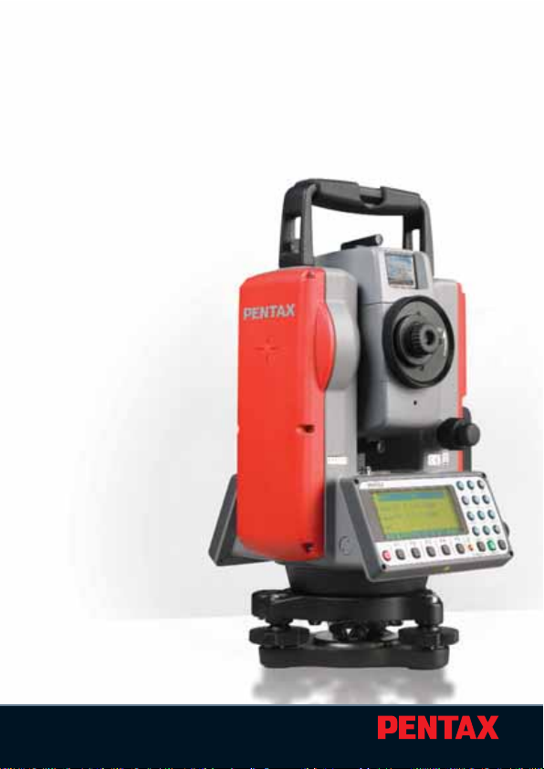
TOTAL STATION
QUICK
REFERENCE
GUIDE
BASIC PROCEDURES
AND POWERTOPOLITE
OPERATING PROCEDURE
V-325DN
SERIES
Page 2

Electronic T otal Station
Quick Reference Guide
Basic Procedures
for V-325DN
and
Po werTopoLite
Operating Procedure
PENTAX Industrial Instruments Co.,Ltd.
Page 3

5
CONTENTS
General 8
Instruction Manuals 8
Precautions regarding safety 8
Warning 8
Usage Precautions 9
I Basic Procedures for V-325DN
1 Basic Operation 10
1.1 Removing the Battery 10
1.2 Attaching the Battery 10
1.3 Turning the Power On and Off 10
1.4 Angle Measurement 10
1.4.1 Horizontal Angle 10
1.4.2 Vertical Angle 11
1.5 Distance Measurement 11
1.5.1 Select your target 11
1.5.2 Distance Measurement 11
1.5.3 Changing Target constants 12
1.5.4 Input Temperature and Atmospheric pressure 12
1.5.5 Laser pointer 12
1.5.6 Adjusting LCD contrast 13
1.5.7 Adjusting Illumination brightness 13
2 Changing Instrument Settings 13
3 Basic Field Checking Procedures 15
3.1 Laser Pointer 15
3.2 Warning and Error Messages 16
3.3 Atmospheric Correction 17
4 Digital Camera 18
4.1 Turning the camera On and Off 18
4.2 Taking pictures 18
4.2.1 Taking pictures and measuring distance
at the same time 18
4.2.2 Taking pictures without measuring distance 18
4.3 Playing back images 18
4.4 Adjusting the camera settings 19
>>
Page 4

6
CONTENTS
>>
4.5Output of image data 19
4.5.1 Remove the SD card from Digital Camera 19
4.5.2 Connecting Digital Camera to a computer
by USB cable 19
5 Specifications 20
Notice to the user of this product 22
II PowerTopoLite Operating Procedure
1 Starting Special Function 24
2 Camera Function 24
2.1 Auto snap 24
2.2 Manual snap 24
3 Creating / Selecting a Job File 25
4 Input a Known Point Coordinate 25
5 Rectangular Coordinate Measurement 26
5.1 Station Point Setup 26
5.2 Orientation (Station Point H.Angle Setup) 27
5.3 Measurement 28
5.4 Offset Measurement 29
5.5 Remote Measurement 29
6 Polar Coordinate Measurement 30
6.1 Station Point Setup 30
6.2 Orientation (Station Point H.Angle Setup) 31
6.3 Measurement 31
6.4 Offset Measurement 32
7 Free Stationing 33
7.1 Known Point Setup 33
7.2 Measurement 33
7.3 Calculation 33
>>
Page 5

7
CONTENTS
>>
8 Stake Out 34
8.1 Station Point Setup 34
8.2 Orientation (Station Point H.Angle Setup) 34
8.3 Stakeout Point Setup 35
8.4 Stakeout Measurement 35
9 Stake Out (Point to Line) 36
9.1 Station Point Setup 36
9.2 Orientation (Station Point H.Angle Setup) 36
9.3 Point A Setup 37
9.4 Point B Setup 37
9.5 Point to Line Measurement 37
10 Traverse Measurement 38
10.1 Measurement at the Start Point 39
10.2 Measurement at a Corner Point 40
10.3 To Finish the Traverse Measurement 41
10.4 Traverse Calculation 41
11 Cogo 42
Calculation Parameters and Output 43
12 Area Calculation 44
13 3D Surface and Volume Calculation 44
14 REM (Remote Element Measurement) 45
15 RDM (Remote Distance Measurement) 46
16 VPM (Virtual Plane Measurement) 46
17 Changing Preference 47
Preference List 48
Page 6
8
Instruction Manuals
Quick Reference Guide is intended to provide a quick referenc e in the
field.For ease of use in the field,the following Quick Reference Guide
booklets are provided in the carrying case.
1. Basic procedure
2. PowerTopoLite Operating procedure
The complete instruction manuals are contained on the CD that is
attached to each V-325DN.
This guide uses the symbol “
xN
”as an expression of repeating times
of key operation. For example. “ x2” means that [ESC] key is
pressed two times.
The symbol “+”expresses that multiple keys are pressed simultaneously.
PRECAUTIONS REGARDING SAFETY
Before using this product, be sure that you have thoroughly read
and understood the instruction manual that is included in the
attached CD-ROM to ensure proper operation.
WARNING
Solar Observation
Never view the sun directly using the telescope as this may result
in loss of sight.
Laser Safety
V-325 is Class IIIa (3R) Laser product.
Do not look into the laser radiation aperture directly as this
may result in damage to your eyes.
Page 7

9
Electro-Magnetic Compatibility (EMC)
This instrument complies with the protection requirement for
residential and commercial areas.If this instrument is used close to
industrial areas or transmitters,the equipment can be influenced
by electromagnetic fields.
Risk of Explosion
Do not use this product in a location where there is coal dust, or
near flammable material as there is a risk of explosion.
USAGE PRECAUTIONS
Target Constant
Confirm the Target Constant of the instrument before measurement.
Reflectorless and Reflecting sheet
The reflectorless measurement range may vary depending on the
target and surrounding brightness.
In case the reflectorless measurement results in low accuracy,
perform the distance measurement by Prism.
Battery & Charger
Use the battery charger that is suitable to the battery you are using.
If water should happen to splash on the instrument or the battery,
wipe it off immediately and allow it to dry in a dry location.
Page 8
10
I Basic Procedures for V-325DN
1.Basic Operation
1.1 Removing the Battery
(1) Rotate the knob above the battery pack counter-clockwise.
(2) Lift up the batter y pack and remove it from the instrument.
1.2 Attaching the Battery
(1) Place the channel on the bottom of the battery pack,onto the
protrusion of the instrument and push the battery pack down
into place.
(2) Turn the knob clockwise.
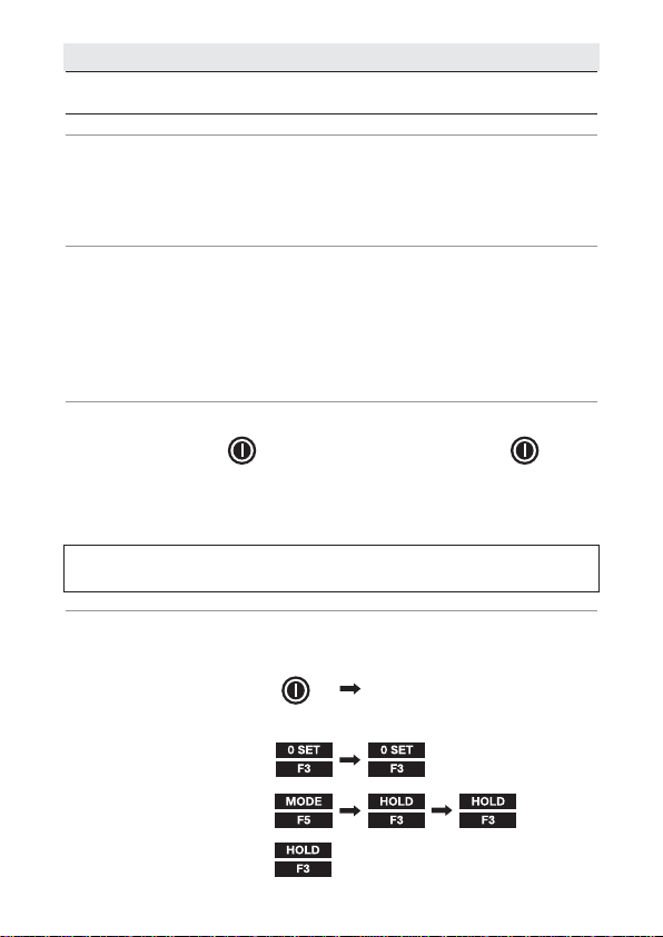
1.3 Turning the Power On and Off
To set power on : To shut down :
To turn the power supply off,press the I/O key for more than
1 second and then release it.Power turns OFF.
NOTE: The power is automatically turned off after 10 minutes
of inactivity (Factory default setting).
1.4 Angle Measurement
1.4.1 Horizontal Angle
Set the screen MODE A :
MODE A screen
Control keys for measuring horizontal angle:
To set the angle to 0 :
To hold the angle :
To release HOLD :
Page 9
11
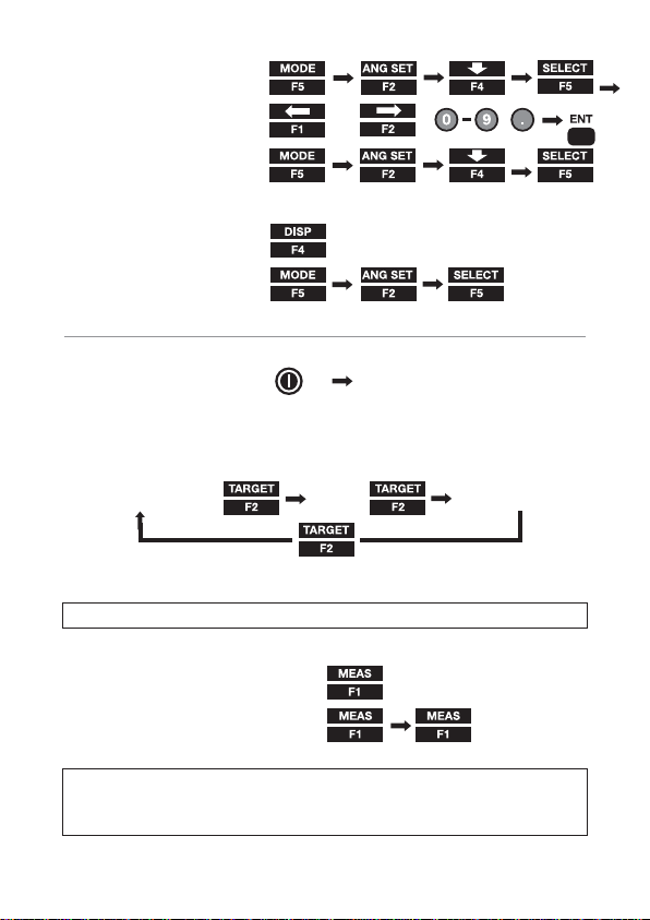
To input an angle :
To read clockwise angle :
1.4.2 Vertical angle
To display vertical angle :
To read the slope % :
1.5 Distance Measurement
Set the screen MODE A:
MODE A screen
1.5.1 Select your target
Select target type (measurement mode):
(Reflecting sheet) (Prism) (Reflectorless)
NOTE:The selected target is maintained until next time you change.
1.5.2 Distance measurement
For a single shot measurement:
For tracking measurement :
NOTE: The number of shots can be defined.The default is
“one time”.The measuring modes activated by the above operations
can be also changed.
,
,
,
input value by using:
x2
Page 10
12
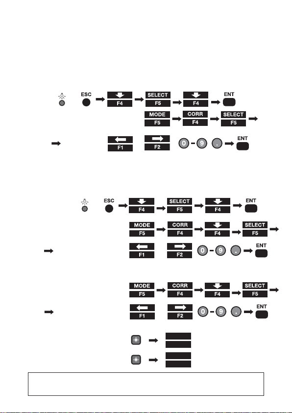
1.5.3 Changing Target constants
The default constants are:
Prism : -30mm
Reflector-less : always 0mm (V-325DN)
Sheet :0mm
Before changing the constants, set Target Constant in the Initial
Setting to“INPUT”mode:
To change Prism constant:
1.5.4 Input Temperature and Atmospheric pressure
The default atmospheric correction mode is “ATM INPUT”.
Before manual input,change the default mode to “ppm INPUT”:
To Input temperature :
To Input atmospheric pressure:
1.5.5 Laser pointer
To activate Laser pointer :
To quit Laser pointer :
NOTE: The laser pointer is kept activated until it is deactivated by
the above procedure.
x2
x3
+
input value
by using:
,
,
,
x2
x2
x2
x2
input value by using:
,
,
,
x2
x3
input value by using:
,
,
,
x2
+
x2
LASER
Camera
LASER
Camera
F1
RED MARK
F1
RED MARK
Page 11
13
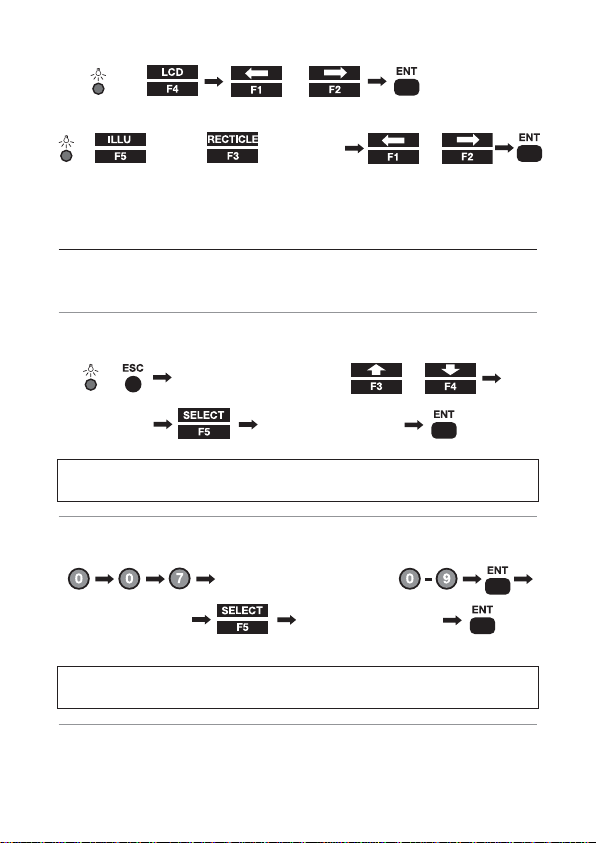
1.5.6 Adjusting LCD contrast
or
1.5.7 Adjusting Illumination brightness
for LCD (for Reticle) or
2.Changing Instrument Settings
You can change the instrument settings by “HELP”menu or by
inputting “007”code.
2.1 Help menu
While the screen is in MODE A or MODE B,
Select a desired item by or
NOTE: Some items have sub-menus where the selecting
procedure by using F1 - F4 is again repeated.
2.2 “007”code
While the screen is in MODE A or MODE B,
Input 007 code by using
NOTE: Some items have sub-menus where the selecting
procedure by using F1 - F4 is again repeated.
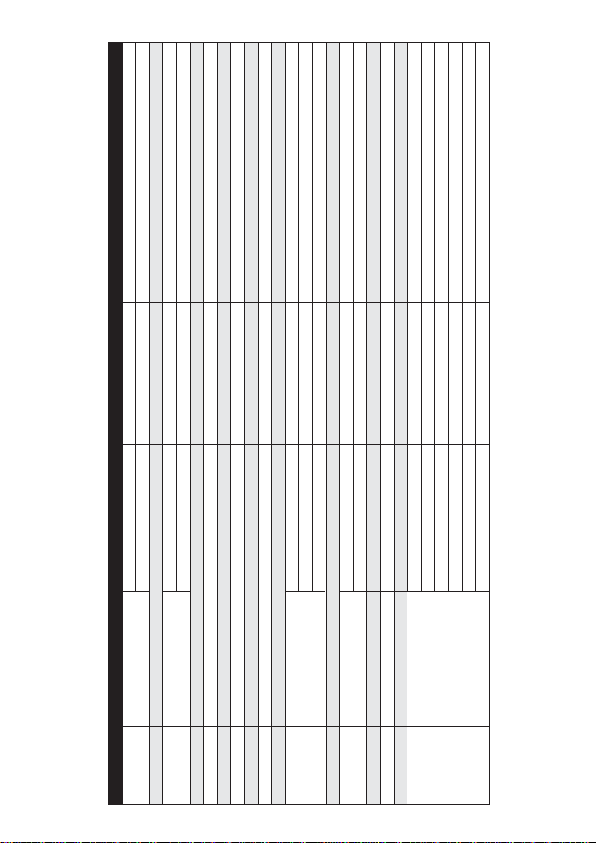
2.3 Instrument setting items
See chart on page 14
+
+
Change the setting
Change the setting
x2
+
Page 12
14
007 code HELP menu list Default Other options
401 TARGET CONST PRISM CONST -30mm 0mm,INPUT
SHEET CONST 0 mm INPUT
402 ATM CORR ATM INPUT ppm INPUT,NIL
502 SHOT COUNT SHOT CONT 1 time 3 times,5 times, INPUT
SHOT INPUT 01 times (input)
503 CRV/REF CORR 0.14 0.2,NIL
504 MIN UNIT ANG. COARSE FINE
505 V.ANG. STYLE Z.0 H.0,COMPASS
509 QUAD BUZ OFF ON
510 AUTO OFF 10 MIN 20 MIN, 30 MIN, NIL
511 EDM OFF ON OFF
517 COMPENSATOR ON OFF
521 REF.LESS LANGE REF.LESS LANGE NORMAL LONG
LONG LANGE MES. ON OFF
LONG LANGE SETUP EACH TIME PERMANENT
523 ATM CORR DISP ON OFF
701 ATM UNIT TEMP.UNIT Centigrade Fahrenheit
PRESS UNIT hPa mmHg,inchHq
702 DIST.UNIT m ft+inch,ft
703 ANG.UNIT DEG DEC,GRD,MIL
801 SET UP COM. BAUD RATE 1200 2400 4800 9600
DATA LENGTH 8
PARITY BITS NIL EVEN,ODD
STOP BITS 1 2
SIGNAL CONTROL ON OFF
XON/XOFF ON OFF
THROUGHT COMMAND NIL a,b,c,d,e,f
Page 13

15
3.Basic Field Checking Procedures
Checks and Adjustments should be performed before and during
measurement.
3.1 Laser Pointer
To activate the laser pointer:
Check if the projected laser spot points at the same position that is
aimed by the center of the cross-hair line of the telescope.
To adjust the laser pointer:Consult your local dealer.
LASER
Camera
F1
RED MARK
Page 14

16
3.2 Warning and Error Messages
Warning Message
Meaning What to do
Displayed when the instrument is
tilted beyond the vertical compensation
range (±3’) in case automatic compensation is selected.This message may be
temporarily displayed if the instrument
is turned too fast.
The input data exceeds the allowable
range.
• This message is displayed if a long
distance which is a far beyond
measurable distance of V-325DN
series is measured with a wrong
target mode.
Please select a correct target then
measure.
If a wrong target is selected,a
correct distance cannot be
measured.
• The measurement distance is less
than 1.5m in Reflector sheet mode.
• The measurement distance is less
than 1.5m in Prism mode.
• Under too strong sun light.
• Unstable light value owing to
shimmer or obstacles.
• Target and Prism do not face
the instrument.
• Target and Prism are not correctly
sighted.
• Measurement range is over in
Reflectorless mode.
• Sufficient signal does not return by
sighting sharp edge etc. at
Reflectorless mode.
Re-level the instrument.
Repair is needed if the
message is displayed
when it is properly
leveled.
Press the [ESC] key and
enter the correct data.
Select the correct target
mode.
Select a longer point,
or use a tape measure.
Change the object
that has much better
reflectivity,or wait until
the sun activity
has weakened.
Out of tilt range
Excess data
Mismatched
Target
Target is too
close.
Unsuitable
Condition
Page 15

17
ERROR!! EDM ERROR
04 -05,34-39,50-53
ERROR!!
ETH ERROR 70-76
ERROR!!
MEMORY ERROR 19
ERROR PS DATA of EDM
ERROR P DATA of EDM
ERROR ETH DATA
Distance measurement system problem
Angle measurement system problem
Memory problem
Problem of the internal EDM parameters
Problem of the internal ETH parameters
Turn the power
off,and then turn on
again.Repair is
needed when the
message appears
consistently.
Error Message Meaning What to do
3.3 Atmospheric Correction
The speed at which light travels through the air varies depending
on the temperature and atmospheric pressure.The V-325DN is
designed to measure distances at the speed of light in order to
measure accurately, atmospheric correction needs to be used.
The instrument is designed to correct for weather conditions
automatically if the temperature and pressure are input.
Correction is then carried out based on the following formula.
Calculation formula:
K= (276.26713 -
78.565271 • P
) x10
-6
K:Atmospheric Correction Constant
P:Atmospheric pressure (hPa)
t:Temperature(°C)
Distance after Atmospheric Correction D = Ds (1+K)
Ds:Measured distance when no Atmospheric Correction is used.
273.14941 + t
Page 16
18
4.Digital Camera
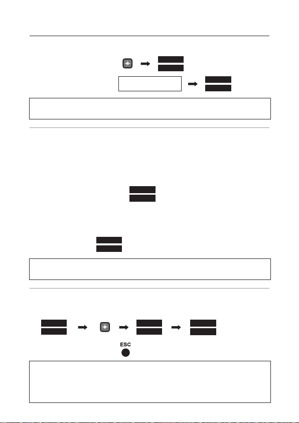
4.1 Turning the camera On and Off
To set the camera On:
To set the camera Off: View 1/3 Screen
NOTE: The part of function key assignment for the display panel
will be changed depending on power ON/OFF of the camera.
4.2 Taking pictures
Take a picture in the View mode ,which is the first display when the
camera is activated.
4.2.1 Taking pictures and measuring distance at the same time
Sight the target by the telescope.
To measure the distance :
4.2.2 Taking pictures without measuring distance
Aim the target when using the telescope or the camera display.
To take a shot :
NOTE: A Point mark can be displayed on each image.This function
can be pre-set by selecting ON/OFF from the setting menu.
4.3 Playing back images
The images can be checked by ReView mode.
To cancel ReView mode:
NOTE: In the event that the aimed point and the Point Mark do not
coincide.Please refer the chapter of "basic procedures" on
the instruction manual for adjusting camera axis using
Current Center Mode.
LASER
Camera
F4
CAMERA ON
F4
CAM OFF
F1
MEAS
F3
SNAP
LASER
Camera
F5
REVIEW
F4
CAMERA ON
F4
REVIEW
Page 17

19
4.4 Adjusting the camera settings
Snap and photo conditions are defined in the Setting menu in the
camera settings.
4.5 Output of image data
The image data and the survey information are stored in the memory.
The information stored in memory can be output to a computer by
using following interface;
4.5.1 Remove the SD card from Digital Camera
Confirm the camera power is off, and take the SD card from the
camera slot.
An SD card with the capacity up to 1GB can be used.
Make sure that the camera power is off before taking the card from
the slot.
4.5.2 Connecting Digital Camera to a computer by USB cable
Confirm the digital camera power is off and connect the camera
to a computer by a USB cable.
Make sure that the camera power is off when disconnecting the
USB cable.
LASER
Camera
F3
SETTING
Page 18

20
5.Specificaties
V-325 DN
TTeelleessccooppee
Magnification 30 x
Resolving power "3"" "
Field of view 2.6% (1°30')
Minimum focus 1.0 m
Reticle Illumination Yes
EEDDMM
Laser Class Visible Laser :class II (2) / class III R (3R)
(Selectable)
Measurement range (Good condition)
Reflectorless - Standard 1.5 _ 90 m
Reflectorless - Long Range Mode 1.5 _ 250 m
Reflector Sheet 1.5 _ 800 m
Mini Prizm(40km visibility) _ 1100 m
1P(40km visibility) 3400 m (4500 m)
3P(40km visibility) 4500 m (5600 m)
Accuracy
Reflectorless 1.5 m _ 200 m : ± (5 + 2 ppm x D) mm
200 m _ 200 m : ± (7 + 10 ppm x D) mm
Prism / Reflector Sheet 10 m _ : ± (2 + 2 ppm x D) mm
1.5 m _ 10 m : ± (3 + 2 ppm x D) mm
Measurement time (minimum count) Prism / Reflector Sheet
Minimum Reading - Normal 2.0sec.(1 mm)
Minimum Reading - Track 0.4sec.(10 mm)
Laser Pointer Yes
Automatic Atmospheric Correction No
AAnnggllee mmeeaassuurreemmeenntt
Measuring system Absolute rotary encoder
Detection method Vertical / Horizontal angle : Single
Minimum count "5"" / 1"" "
Accuracy(ISO17123-3) "5"""
Vertical angle compensation Single Axis
Tangent Screw 1 Speed
DDiiggiittaall CCaammeerraa((DDSSCC))
Sensor CMOS 3.1 megapixels
Image resolution 2048 x 1536 / 1600 x 1200 / 1280 x 960 / 640 x 480
LCD "1.5"" Color TFT 34 mm x 24 mm (502 x 240 dot.)"
EV compensation -2EV_+2EV ( 0.5EV step )
WhiteBlance Auto/Daylight/Light Bulb/Fluorescent/Cloudy
ISO Sensitivity 100 / 200 / 400
File format JPEG ( FQ:1/4, NQ:1/8,EQ:1/16 )
File management DCF(Ver1.0) / FAT16
Disital zoom 1x / 2x / 3x
Play back function Yes
External memory SD ( up to 1GB )
Focus length 50 mm
Focus range 20 m _ ∞ (fixed focus length)
Field of view 8.8°
Effective Diameter f/5.6
I/F USB 2.0
Power Internal (Supplied from TS battery)
Page 19

21
5.Specificaties
V-325 DN
DDaattaa PPrroocceessss ((TTSS))
Data recording method Internal Memory
Internal Memory 30000 point
Clock function Yes
Special function PTL + DSC
I/F RS-232C
DDiissppllaayy // KKeeyybbooaarrdd
LCD Full DotMatrix STN LCD Two side
Language English
Keyboard Alphanumeric Key (10 Keys)
SSeennssiittiivviittyy ooff vviiaallss
Plate level (electronic) "40""/2 mm "
Circular level 8'/2 mm
PPlluummmmeett
Optical Plummet
BBaassee
Detachable
DDuusstt aanndd WWaatteerr PPrrootteeccttiioonn
IP55
WWoorrkkiinngg tteemmppeerraattuurree
-20° C ~ +50° C / -4° F ~122° F
PPhhyyssiiccaall
Dimension 172(W) x 343(H) x 177(L) mm
Weight 5.4 kg
Battery BP02
Battery charger BC03 + AC01
Page 20

22
NOTE:
* The measurement range may vary by measurement conditions.
* Normal conditions:20km visibility with slight shimmer.
* Good conditions:40km visibility,overcast,no heat,no shimmer
and moderate wind.
* EDM Measuring time varies according to distance to be
measured and conditions of the environment.
* Reflectorless V-325DN:
- The measurement range and accuracy of Reflectorless are based
on the condition that laser beam is emitted perpendicular to the
white side of the Kodak Gray Card.
- The measurement range may be influenced by the shape
of the target and its environment.
- The measurement range at TRACK mode is over 5m.
- It takes time,longer than usual,
to measure the distance to the
object that is hard to measure.
- The measurement range,accuracy of distance measurement and
time required to measure may be influenced by the shape,size of
surface area and reflection rate of the target and its environment.
* The operating time becomes shorter under the low temperature,
due to the temperature dependence of the battery performance.
NOTICE TO THE USER OF THIS PRODUCT
To assure compliance with the Safety standard 21 CFR, Chapter 1.
Subchapter J. The U.S. bureau of Radiological Health requires the
following information to be provided to user.:
It can be dangerous to look into the beam with optical equipment such as binoculars and telescopes.
1. Specifications of Laser Radiation
A) The EDM module of the V-325DN produces a visible light beam,
which is emitted from the telescope objective lens and the center
hole of the instrument base plate.The V-325DN is designed and
built to have a laser diode radiating at 620-690nm.
Page 21

23
B) Radiant power
The V-325DN is designed and built to radiate a maximum aver
age radiant power of 4.75mW from the telescope.The user may
be subject to this radiation as a beam while operation until such
time that the instrument is turned off.
2. The following labels are affixed to and must remain
attached to this laser product.
A) The following Certification label is located near the Plate level:
“This laser product is complied with the provisions of 21 CFR
1040.10 and 1040.11.For a Class II laser product.”
B) Or for V-325DN models:
"This laser product is complied with the provisions of 21 CFR
1040.10 and 1040.11.For a Class IIIa laser product."
C) Caution label is located near the exit aperture:
“AVOID EXPOSURE.Laser radiation is emitted from this aperture.”
D) Warning logotype is located on the surface of the telescope:
“CAUTION LASER RADIATION DO NOT STARE INTO BEAM”
E) Warning label is Located near the exit aperture.
3. Caution to maintain the safety in compliance with the standard
A) To maintain the safety standard,refrain from any operation,
maintenance,or adjustment other than described in this
instruction manual.
B) Operation,maintenance or adjustment other than those specified in
this instruction manual may result in hazardous radiation exposure.
C) Maintenance and repair not covered in this manual must be
done by an authorized Pentax dealer.
D) The Laser beam emission by the Distance measurement
can be terminated by pressing key.
E)
Pressing keys can terminate the laser beam
emission
by the laser pointer.
LASER
Camera
F1
RED MARK
Page 22

24
II PowerTopoLite Operating Procedure
1.Starting Special Function
2.Camera function
The Camera is available in each function of PowerTopoLite.
2.1 Auto snap
When using the function in PowerTopoLite while measuring the
distance,the camera can be activated automatically and takes a
picture during the survey task To use this function,the following
setting must be set to ON beforehand.
NOTE: The par t of function key assignment for the display panel
will be changed depending on power ON/OFF of the camera.
Chapter of "Power TopoLite Operating procedures" explains the
operation in case of the camera power is OFF.
2.2 Manual snap
To active Camera :
Except for a few screens ,the Camera can be activated in all screens
of PowerTopoLite.
To turn the Camera off:
MODE A SCREEN
MODEF5S. FUNC
F1
POWER TOPO LITE
MAIN MENU
F5
PAGE
F5
ACCEPT
F4
PREF
POWER TOPO LITE
MAIN MENU
POWER TOPO LITE
MAIN MENU
select an
Auto snap
select on
x 2
LASER
Camera
F4
CAM OFF
LASER
Camera
F4
CAMERA ON
Page 23

3.Creating / Selecting a Job File
To create a new job file:
Or to select a job file:
NOTE: Once a job file is created or selected, it is effective until a
new job file is created or another job file is selected.
The default job file "PENTAX" is provided permanently
so that data is stored even when no user defined
job file exists.
4.Input a Known Point Coordinate
To input and store a known point coordinate;
NOTE: There are other functions in VIEW menu;Graphical View,
Edit Rectangular Data,and Edit Polar Data.For detail of
these functions,please refer to the instruction manual of
PowerTopoLite.
25
ENT
POWER TOPO LITE
MAIN MENU
FILE
F1
F4
input a new job name by using
F1
TO 123
F5
0.9
DEF
,
ENT
POWER TOPO LITE
MAIN MENU
FILE
F1
F4
x2
x2 select a job file by
ENT
F1
F4
ENT
POWER TOPO LITE
MAIN MENU
VIEW
F3
F4
input a Point Name by using
F1
TO 123
F5
0.9
DEF
,
x2
ENT
repeat to input value
ESC
SAVE
F1
ESC
to quit
x2
ENT
input PC (point code)
ENT
Page 24

To input PC (point code):
NOTE: PC list is displayed only when point codes are stored in
the job named “PointCodeList”. “PointCodeList”job can be
created by the procedure described in the section 2,and
PC can be stored by inputting PN and PC as a point
coordinate data.PC list can be also transferred from a
computer. For more detail,refer to the instruction manual
of PowerTopoLite.
A new point code can be input and memorized as a point
coordinate data,but it is not stored as the data of
“PointCodeList”.If a new PC need to be added to the list,
select “PointCodeList”job and add a PC as a new
Rect.Coord.Data.
5.Rectangular Coordinate Measurement
5.1 Station Point Setup
To select from the memory:
26
ENT
select a PC
from the list by
input a new PC by
move cursor to PC
F1
F4
ENT
F1
TO 123
F5
0.9
DEF
POWER TOPO LITE
MAIN MENU
MEAS
F2
ENT
STATION POINT
SETUP
H. ANGLE
SETUP
LIST
F2
F5
ACCEPT
select
the point by
F2
FIND PN
F4
ENT
ENT
x2
Page 25

27
Or to input the station point information:
NOTE: The input item (cursor position) may be selected by
To input PC (point code):
NOTE:
Input items are PN (point name), X, Y, Z, IH (instrument
height),and PC (point code).
If the input PN already exists in the memory,then the corresponding
point information
(coordinate & point code) is displayed in the screen.
The result of Free Station, prior to stakeout, is automatically
set in each field of Station Setup.
5.2 Orientation (Station Point H.Angle Setup)
To input a given angle:
Or to set the angle 0°:
Or to calculate by the Back Sight Point:
STATION POINT
SETUP
0.9
DEF
input Point
Name by
F1
TO 123
F5
ENT
,
H. ANGLE
SETUP
repeat to
input value
ENT
ESC
SAVE
F1
to quit
ENT
input PC (point code)
or
F5
ACCEPT
F3
F4
ENT
,
move cursor to PC
ENT
select a PC from the list by
input a new PC by using
F1
F4
ENT
F1
TO 123
F5
0.9
DEF
,
MEASUREMENT
SCREEN
0.9
DEF
input value by using
INPUT
F2
ENT
x2
MEASUREMENT
SCREEN
ENT
x2
MEASUREMENT
SCREEN
input value or select from the list
ENT
LIST
F2
F5
ACCEPT
aim Back Sight Point
ENT
ENT
x2
F3
0 SET
F1
BSP
Page 26

28
5.3 Measurement
To select the Target type:
NOTE: You can check the selected target type at the left side
of the Battery mark in the top line of the screen.
To measure:
Or to start tracking:
NOTE: EDM measurement mode can be changed by
To input the point information:
To save the point information:
Or to measure and save:
NOTE: the Point number is automatically incremented or
decremented to make rapid continuous measurements
possible.When ‘Auto snap’is ON,the sur vey data and the
picture is saved by pressing the or
press
PAGE
F5
TARG ET
F2
PAGE
F5
x2 to select the desired target type
MEASF1MEAS
F1
x2
PAGE
F5
x2
EDM
F1
select and change the EDM mode
0.9
DEF
move cursor by
F3
F4
ENT
,
RETURN TO THE
MEASUREMENT
SCREEN
repeat to input value
ENT
ESC
to quit
ENT
input point code
F5
ACCEPT
EDIT
F4
,,
F1
TO 123
F5
input values by using
SAVE
F2
(next measurement)
ME/SAVE
F3
(next measurement)
F3
ME/SAVE
F2
SAVE
Page 27

29
5.4 Offset Measurement
For Radial Offset (the horizontal distance offset along the line of
measurement):
For T angential Offset:
For Distance Offset (slope distance):
NOTE: The Offset values are cleared once the measurement is
saved.
5.5 Remote Measurement
To enter the Remote mode:
or
MEASUREMENT
SCREEN
0.9
DEF
input value
by using
PAGE
F5
OFFSET
F2
ENT
ENT
ESC
F5
ACCEPT
RETURN TO THE
MEASUREMENT
SCREEN
MEASUREMENT
SCREEN
0.9
DEF
x3
PAGE
F5
OFFSET
F2
ENT,ENT
RETURN TO THE
MEASUREMENT
SCREEN
F4
input value by using
MEASUREMENT
SCREEN
0.9
DEF
x2
PAGE
F5
OFFSET
F2
ENT
,
ENT
RETURN TO THE
MEASUREMENT
SCREEN
F4
input value by using
ESC
F5
ACCEPT
MEASUREMENT
SCREEN
x2
PAGE
F5
REMOTE
F1
PAGE
F5
x2
MEAS
F1
RETURN TO THE MEASUREMENT
VALUES ARE UPDATED BY
TURNING THE TELESCOPE
EDIT
F4
Input PN,PH
ESC
F5
ACCEPT
SAVE
F2
(next measurement)
ENT
input PC
MEASUREMENT
SCREEN
MEAS
F1
PAGE
F5
REMOTE
F1
x2
REMOTE MODE
MEASUREMENT VALUES ARE
UPDATED BY TURNING THE
TELESCOPE
EDIT
F4
Input PN,PH
ESC
F5
ACCEPT
SAVE
F2
(next measurement)
ENT
input PC
PAGE
F5
Page 28

30
NOTE: Remote values are calculated based on the assumption of
the reference plane.Three types of the reference plane are
available in PowerTopoLite;Cylindrical surface,Fixed plane
(default) and Rotated plane.
To change the reference plane type:
To quit the Remote mode:
6.Polar Coordinate Measurement
6.1 Station Point Setup
To input the point information:
NOTE: Input items are PN (point name), IH (instrument height),
PC (point code),TEMP (temperature), PRESS (atmospheric
pressure) and ppm."TEMP" and "PRESS" can be input only
when "Atmospheric Correction" is set to "ATM INPUT".
"ppm" can be input only when "Atmospheric Correction"
is set to "ppm INPUT".
The input item (cursor position) may be selected by
POWER TOPO LITE
MAIN MENU
x2
PAGE
F5
PREF
F4
F4
x3
F4
ENT
select by using
F3
,
ENT
PAGE
F5
REMOTE
F1
x2
MEASUREMENT
SCREEN
F5
ACCEPT
MEAS
F2
F4
STATION POINT
SETUP
POWER TOPO LITE
MAIN MENU
ENT
ENT
input Point Name by
0.9
DEF
,
F1
TO 123
F5
ENT
repeat to input value
H. ANGLE
SETUP
ESC
SAVE
F1
to quit
ENT
or confirm “ppm”
F4
F3
,
ENT
Page 29

31
6.2 Orientation (Station Point H.Angle Setup)
Only when the orientation of the horizontal angle is required,
proceed according to the following procedure.
Otherwise,just pass this step by
To input a given angle:
Or to set the angle 0°:
Or to calculate by Inverse:
6.3 Measurement
To select the Target type:
NOTE: You can check the selected target type just at the left of the
Battery mark in the top line of the screen.
To measure:
Or to start tracking:
NOTE: EDM measurement mode can be changed by
input value by using
0.9
DEF
INPUT
F2
ENT
MEASUREMENT
SCREEN
x2
ENT
MEASUREMENT
SCREEN
x2
ENT
MEASUREMENT
SCREEN
select Start Point from the List
LIST
F2
ENT
F5
ACCEPT
LIST
F2
select End Point
from the List
ENT
F5
ACCEPT
ENT
x2
PAGE
F5
x2 press to select the desired target type
TARG ETF2PAGE
F5
MEAS
F1
MEAS
F1
x2
PAGE
F5
x2
EDM
F1
select and change the EDM mode
ENT
F3
0 SET
F1
INVERS
Page 30

32
To input the point information:
To save the point information:
Or to measure and save:
NOTE: The point number is automatically incremented or
decremented for rapid continuous measurements.
When ‘Auto snap’is ON,the survey data and the
picture is saved by pressing the or
6.4 Offset Measurement
For Radial Offset (horizontal distance offset along with the line of
measurement):
For Distance Offset (slope distance offset):
NOTE: The O ffset values are cleared once the measurement
is saved.
ENT
input
Point Name by
0.9
DEF
,
F1
TO 123
F5
ENT
repeat to input value
RETURN TO THE
MEASUREMENT
SCREEN
ESC
to quit
ENT
Input PC
EDIT
F4
F5
ACCEPT
(next measurement)
SAVE
F2
(next measurement)
ME/SAVE
F3
input value
by using
MEASUREMENT
SCREEN
ENT
PAGE
F5
RETURN TO THE
MEASUREMENT
SCREEN
OFFSET
F2
0.9
DEF
ENT
ESC
F5
ACCEPT
input value by using
MEASUREMENT
SCREEN
ENT
PAGE
F5
RETURN TO THE
MEASUREMENT
SCREEN
OFFSET
F2
0.9
DEF
ENT
ESC
F5
ACCEPT
(point
code)
F3
ME/SAVE
F2
SAVE
Page 31

33
7.Free Stationing
7.1 Known Point Setup
Select the point from the stored data:
Or input PN which is already stored in memory to call and display the
known coordinate.
7.2 Measurement
Select the target type and measure:
NOTE: You can check the selected target type just at the left of the
Battery mark in the top line of the screen.
To proceed to the next point:
Repeat "6.1 Known Point Setup" and "6.2 Measurement" for all known points.
7.3 Calculation
input Inst.Height (IH) by using
0.9
DEF
ENT
FREE
F4
POWER TOPO LITE
MAIN MENU
KNOWN POINT
SETUP
select the point by
LIST
F2
MEASUREMENT
SCREEN
F2
FIND PN
F4
ENT
F5
ACCEPT
press
TARG ET
F2
to select until the desired target type
MEAS
F1
KNOWN POINT
SETUP
ENT
ADD
F1
input
Point Name
CALC
F5
MEASUREMENT
SCREEN
RETURN TO
POWER TOPO LITE
MAIN MENU
ENT
F5
ACCEPT
ENT
ENT
ENT
select Point Code from the list or input
ESC
to quit
F5
ACCEPT
Page 32

34
NOTE: The result of Free Station is automatically carried
forward to the station setup of Rectangular coordinate
measurement and stakeout.
8.Stake Out
8.1 Station Point Setup
Select from the stored data:
Or input PN which is already stored in the memory to call and display
the known coordinate.
NOTE: The result of Free Station,prior to stakeout, is
automatically set in each field of Station Setup.
8.2 Orientation (Station Point H.Angle Setup)
To input a given angle:
Or to set the angle 0°:
Or to calculate by the Back Sight Point:
POWER TOPO LITE
MAIN MENU
ENT
PAGE
F5
STAK
F1
STATION POINT
SETUP
H. ANGLE
SETUP
ENT
LIST
F2
F2
FIND PN
select the point by
F4
F5
ACCEPT
STAKEOUT
COORD. SETUP
ENT
INPUT
F2
input the value x2
STAKEOUT
COORD. SETUP
ENT
x2
STAKEOUT
COORD. SETUP
ENT
select the point by
F2
FIND PN
F4
F5
ACCEPT
ENT
LIST
F2
F3
0 SET
F1
BSP
Page 33

8.3 Stakeout Point Setup
Select the point from the stored data:
8.4 Stakeout Measurement
Check the designed value.If “COMPARE METHOD”is set to
“LARGE CHARACTER”, press to proceed to the Stakeout screen
Turn the instrument until "DH.Angle" reads to "0".
Select the Target type:
NOTE: You can check the selected target type just at the left of the
Battery mark in the top line of the screen.
To measure in Tracking mode:
To confirm the position of the stake:
To proceed to the next point:
35
STAKEOUT
MEASUREMENT
ENT
select the
point by
F2
FIND PN
F4
F5
ACCEPT
repeat
TARG ET
F2
until the desired target type is selected
MEAS
F1
x2 (move the target until “DH.dist”reads “0”)
MEAS
F1
To quit measurement
(position the target accurately)
PAGE
F5
F1
RECT. M
MEAS
F1
EDIT
F4
Input PN,PH and PC
SAVE
F2
ESC
RETURN TO STAKE-
OUT MEASUREMENT
SCREEN
NEXT
F4
STAKEOUT
MEASUREMENT
(repeat from “Stakeout Point Setup)
SCROLL
F3
LIST
F2
Page 34

36
9.Stake Out (Point to Line)
"Point to Line" gives the distances between SOP and Int.P,A and Int.P,
B and Int.P.
9.1 Station Point Setup
Select the point from the stored data:
NOTE: The result of Free Station,prior to stakeout, is
automatically set in each field of Station Setup.
9.2 Orientation (Station Point H.Angle Setup)
To input a given angle:
Or to set the angle 0°:
Or to calculate by the Back Sight Point:
POWER TOPO LITE
MAIN MENU
ENT
STAK
F1
F4
PAGE
F5
STATION POINT
SETUP
A Int. P
SOP
B
H. ANGLE
SETUP
ENT
LIST
F2
select the point by
F2
FIND PN
F4
F5
ACCEPT
POINT A SETUP
ENT
INPUT
F2
input the value x2
POINT A SETUP
ENT
select the point by
F2
FIND PN
F4
F5
ACCEPT
POINT A SETUP
ENT
x2
ENT
LIST
F2
F3
0 SET
F1
BSP
Page 35

37
9.3 Point A Setup
To input values:
Or to select from the memory:
9.4 Point B Setup
To input values:
Or to select from the memory:
9.5 Point To Line Measurement
To select the Target type:
NOTE: You can check the selected target type just at the left of the
Battery mark in the top line of the screen.
ENT
input Point Name by
0.9
DEF
,
F1
TO 123
F5
ENT
repeat to
input value
POINT B SETUP
ESC
to quit
ENT
Input PC (Point Code)
SAVE
F1
or
F5
ACCEPT
POINT B SETUP
ENT
LIST
F2
select the
point by
F2
FIND PN
F4
F5
ACCEPT
ENT
input Point Name by
0.9
DEF
,
F1
TO 123
F5
ENT
repeat to
input value
MEASUREMENT
ESC
to quit
ENT
Input PC (Point Code)
SAVE
F1
or
F5
ACCEPT
MEASUREMENT
ENT
LIST
F2
select the
point by
F2
FIND PN
F4
F5
ACCEPT
press
TARG ET
F2
to select the desired target type
Page 36

38
To measure in Tracking mode:
To confirm the position of the stake:
10.Traverse Measurement
Traverse Measurement is based on the following assumptions:
• The current station is the foresight point of the previous station.
• The back sight point of current station is the previous station.
Limitations are:
• More than one traverse route can not be measured at the same
time.
• Do not store other data while you are measuring the traverse route.
• When one traverse route is finished,perform the traverse calcula-
tion before you store other data.
• Do not turn the power supply off until all the measurement at one
start point or at one corner point is completed.
• Do not escape from the MEASURE screen.
• The same PN should not be used in one Job.And the PN can not
be overwritten in the traverse.
• The same traverse route can not be calculated again.
• Polar coordinates data of back sight and station points can not be
seen in the POLAR EDIT function, but it is sent properly in SEND
POLAR DATA function.
MEAS
F1
x2 (move the target to the desired position)
MEAS
F1
To quit measurement
(position the target accurately)
PAGE
F5
F1
RECT. M
MEAS
F1
EDIT
F4
Input PN,PH and PC
SAVE
F2
ESC
RETURN TO STAKE-
OUT MEASUREMENT
SCREEN
x2
Page 37

39
To start Traverse:
10.1 Measurement at the Start Point
Start the traverse from the start point measurement.
Station Setup:
Orientation (Station Point Setup):
or to set the angle 0°:
or to calculate by the known points (Start point and End point):
Side shot measurement:
POWER TOPO LITE
MAIN MENU
PAGE
F5
TRAV
F1
TRAVERSE
MENU
x2
TRAVERSE
MENU
ENT
STATION SETUP
ENT
input Point Name by
0.9
DEF
,
F1
TO 123
F5
ENT
repeat to input value
H. ANGLE
SETUP
ESC
to quit
or confirm “ppm”
input value by using
0.9
DEF
ENT
INPUT
F2
x2
SIDE SHOTS
x2
ENT
SIDE SHOTS
LIST
F2
select Start Point from the List
F5
ACCEPT
select End Point
from the List
ENT
ENT
F5
ACCEPT
LIST
F2
ENT
ENT
x2
SIDE SHOTS
EDIT
F4
for all side shots
MEAS
F1
repeat
,
SAVE
F2
,
MEAS
F1
finish measurements by
EDIT
F4
,
,
ENT
at the
Corner Point
ESC
TRAVERSE
MENU
F5
ACCEPTF5ACCEPT
F3
0 SET
F1
INVERS
Page 38

NOTE: The corner point is the foresight of the traverse,which is the
next instrument point and must be ended by
If required,select the target by before each
measurement.
When ‘Auto snap’is ON,the survey data and the
picture is saved by pressing the or
10.2 Measurement at a Corner Point
Station Setup:
NOTE: Input Instrument Height (IH), if necessary.
Orientation:
Side shot:
NOTE: The corner point is the foresight of the traverse,which is the
next instrument point and must be ended by .
If required,select the target by before each
measurement.
When ‘Auto snap’is ON,the survey data and the
picture is saved by pressing the or
ENT
x2
TRAVERSE
MENU
ENT
F4
(the last corner point is displayed as Station)
(sight the back sight point)
ENT
ACCEPT
F5
EDIT
F4
for all side shots
MEAS
F1
repeat
,
SAVE
F2
,
MEAS
F1
finish measurements by
EDIT
F4
,
,
ENT
at the
Corner Point
ESC
TRAVERSE
MENU
PAGE
F5
TARG ET
F2
PAGE
F5
x2
TARG ET
F2
ENT
40
F3
ME/SAVE
F2
SAVE
F3
ME/SAVE
F2
SAVE
Page 39

41
10.3 T o Finish the Trav erse Measurement
Fixed traverse: Measure the known point and press at the last
corner point.
Closed traverse: Measure the star t point and press at the last
corner point with the different Point Name.
NOTE: Use the different point name (PN) when you measure the
start point as the last corner point.For example,change “T1”
to “T1-1”etc.
Open traverse: The closing errors are not calculated.No need to end
the measurement by pressing .
10.4 Tra verse Calculation
To Start Fixed traverse calculation:
NOTE: To select CLOSE TRAVERSE CALC.:
To select OPEN TRAVERSE CALC.:
Start Point Coordinate setup:
or to input the known coordinate;
ENT
ENT
ENT
TRAVERSE
MENU
ENT
F4
F4
F4
x3
x4
END POINT SETUP
ENT
LIST
F2
select the
point by
F2
FIND PN
F4
F5
ACCEPT
ENT
input Point Name by
0.9
DEF
,
F1
TO 123
F5
ENT
input the next value or
END POINT SETUP
ESC
to quit
F5
ACCEPT
x2
Page 40

End Point Coordinate setup: the same operation as in the above.
NOTE: The End Point Coordinate Setup is required only in the fixed
traverse.
Result of Traverse Calculation:
To see the result of each corner point:
To see all points in order:
To save all results:
11.Cogo
To access COGO menu and select calculation type:
Input required parameters:
Save the result:
The required calculation parameters and the output are as follows
(page 39):
42
F2
F1
or
F4
F3
or
F5
ACCEPT
TRAVERSE
MENU
PAGE
F5
POWER TOPO LITE
MAIN MENU
CALC
F2
ENT
select calc.
type by
F4
F3
or
ENT
input parameters by
terminating with
F5
ACCEPT
or
ENT
each time
RESULT SCREEN
ENT
input point name and point code
F5
ACCEPT
RETURN TO
PARAMETER SCREEN
ENT
Page 41

43
Direction Angle (SP->EP)
H,V,S Distance
Coordinate of the
unknown point
Coordinate of centerpoint
of the arc,Radius of the arc
Coordinates of intersect
points (P1,P2)
Coordinate of the
intersect point
Coordinates of intersect
points (P1,P2)
Coordinate of the
intersect point of the line
and a perpendicular line
from the offset point.
Distance of the intersect
point from the SP of the
line
Coordinate of the offset
point
Coordinate of the offset
point
1
2
3
4
5
6
7
8
9
Inverse
Point
Coordinate
Circle Radius
Line-Arc
Intersection
Line-Line
Intersection
Arc-Arc
Intersection
Distance
Offset
Point Distance
Offset
ARC Distance
Offset
SP (Start Point)
EP (End Point)
CO (Known point coordinate)
DI (Distance to the unknown point)
BE (Direction Angle to the unknown point)
Coordinates of three points (P1,P2,P3)
SP (Start point of the line)
EP (End point of the line)
CP (Center point of the circle)
R (Radius of the circle)
S1 (Start point of the 1st line)
E1 (End point of the 1st line)
S2 (Start point of the 2nd line)
E2 (End point of the 2nd line)
C1 (Center Point of the 1st circle)
R1 (Radius of the 1st circle)
C2 (Center Point of the 2nd circle)
R2 (Radius of the 2nd circle)
SP (Start point of the line)
EP (End point of the line)
OP (Offset Point)
SP (Start point of the line)
EP (End point of the line)
DI (Distance on the line from SP)
OD (Offset distance from the line)
SP (Start Point of the arc)
EP (End point of the arc)
R (Radius of the arc)
DI (Distance on the arc from SP)
OD (Offset distance from the arc)
Page 42

12.Area Calculation
To start area calculation:
To return to the calculation menu screen:
NOTE: This func tion calculates the length of 2D and 3D contour of
a polygon,and the 2D surface (area) of the polygon.
The polygon is defined by selecting points in such a way
that the contour segments of the polygon do not intersect.
The last selected point is automatically tied to the first
selected point to form the closed figure.
There are several function keys for point selection,such as
"ALL", "FIND PN", FROM", "TO", and "ORDER". Refer to the
instruction manual on the CD-R.
13.3D Surface and Volume Calculation
To start Volume calculation:
PAGE
F5
POWER TOPO LITE
MAIN MENU
CALC
F2
ENT
select points of the polygon by repeating select (
F4
F3
or
ENT
F4
) and
F1
ACCEPT
RESULT SCREEN
ESC
x2
RESULT SCREEN
CALCULATION
MENU SCREEN
PAGE
F5
POWER TOPO LITE
MAIN MENU
CALC
F2
ENT
select points of the polygon by repeating select (
F4
F3
or
ENT
F4
) and
F1
ACCEPT
RESULT SCREEN
VOLUME
input the reference height by
0.9
DEF
ENT
RESULT SCREEN
CONTOUR
SURFACE AREA
ENT
x2
44
Page 43

To return to the calculation menu screen:
NOTE: This func tion calculates the contour, the 2D and 3D sur face
area,and the volumes (positive,negative and total.)
The order of point selection is not important.The number of
points must be less than 350.The 3D polygon is automatcally
defined by the element triangles that are formed by
connecting neighboring points. The positive and negative
volumes are calculated based on the reference height.
14.REM (Remote Element Measurement)
To start REM:
Measure the Reference point:
Measure the elevation of the remote point:
To return to Calculation menu:
45
ESC
x2
RESULT SCREEN
CALCULATION
MENU SCREEN
PAGE
F5
POWER TOPO LITE
MAIN MENU
CALC
F2
F4
ENT
x3
MEAS
F1
ENT
input prism (or reference) height
ENT
aim the point to be measured
REM VALUE IS
DISPLAYED AT THE
BOTTOM OF THE SCREEN
ESC
CALCULATION
MENU SCREEN
x2
Page 44

46
15.RDM (Remote Distance Measurement)
To start RDM:
Measure the Reference point:
Measure the 2nd point (Target Point):
Measure the 3rd point (Target Point):
To change the reference to the present point:
To return to PowerTopoLite Main menu:
16.VPM ( Virtual Plane Measurement)
To start VPM:
Station point setup:
RESULT SCREEN
ENT
POWER TOPO LITE
MAIN MENU
PAGE
F5
POWER TOPO LITE
MAIN MENU
VPM
F3
STATION POINT
SETUP
select the
point by
LIST
F2
H. ANGLE
SETUP
ENT
F2
FIND PN
F4
F5
ACCEPT
PAGE
F5
POWER TOPO LITE
MAIN MENU
RDM
F4
MEASURE THE
REFERENCE POINT
EDIT
F4
input the target height by
0.9
DEF
ENT
MEAS
F1
(select target if necessary)
MEAS
F1
RESULT SCREEN
DISTANCE FROM THE
REFERENCE POINT
MEAS
F1
RESULT SCREEN
DISTANCE FROM THE
REFERENCE POINT
VER.
F5
RESULT SCREEN
DISTANCE FROM THE
PREVIOUS TARGET POINT
RESULT SCREEN
DISTANCE FROM THE
PREVIOUS TARGET POINT
ENT
x2 (repeat reference point measurement)
Page 45

47
H.angle setup:
To input a given angle:
Or to set the angle 0°:
Or to calculate by the Back Sight Point:
Measure three points to define the plane:
Virtual plane measurement:
To return to PowerTopoLite Main menu:
17.Changing Preference
To access Preference menu:
Preference List (page 44)
input the value by
0.9
DEF
INPUT
F2
ENT
x2
THREE POINTS
MEASUREMENT
ENT
x2
THREE POINTS
MEASUREMENT
LIST
F2
Input value or select from the List
F5
ACCEPT
ENT
SAVE
F1
or
THREE POINTS
MEASUREMENT
if necessary,
MEAS
F1
SAVE
F2
ENT
(repeat measurements
of remaining two points)
VPM SCREEN
if necessary,
SAVE
F2
aim a point on the plane
ESC
VPM SCREEN
POWER TOPO LITE
MAIN MENU
PREF
F4
select an item by
PAGE
F5
F4
ENT
F3
or
POWER TOPO LITE
MAIN MENU
POWER TOPO LITE
MAIN MENU
x2
select an option by
F4
F3
or
ENT
F5
ACCEPT
F3
0 SET
F1
BSP
Page 46

48
Preference List
10 KEY SYTEM (123),FULL TEMPLATE,DIVIDED TEMPLATE,
MATRIX SYSTEM
Item
Default
Options
Remark
1
2
3
4
567
8
9
10
11
LANGUAGE
COORD.AXIS
INPUT METHOD
ACTION METHOD
REMOTE METHOD
COMPARE METHOD
REQUEST AIMING
EDM SETTINGS
ELEV.FACTOR
DUPLICATE PN CHK
Auto snap
DISP.1 NAME
DISP.2 NAME
DISP.3 NAME
DISP.1 AXIS
DISP.2 AXIS
DISP.3 AXIS
ROT ATION
PRIM.MEAS KEY
SEC.MEAS KEY
MEAS.MIN DISP.
SHOT COUNT
SHOT INPUT
AVE.ELEV.
SCALE FACT.
ENGLISHXYZBASE DIRECT.
RIGHT ANGLE
HEIGHTCW10 KEY SYSTEM
(ABC)
PROCESS TYPE
FIXEDPLANE
ALL IN ONE INFO.
OFF
MEAS SHOT
TRACK COUNT
COARSE
1 time
01 times
0m
1.0
OFF
ON
YOUR LANGARGE
Any alpha-numeric character
Any alpha-numeric character
Any alpha-numeric character
HEIGHT,RIGHT ANGLE
BASE DIRECTION,HEIGHT
BASE DIRECTION,RIGHT ANGLE
CCW
STRUCTURE TYPE
CYLINDER FACE,ROTATED PLATE
LARGE CHARACTERONMEAS CONT,TRACK SHOT,TRACK CONT
TRACK SHOT,MEAS CONT,MEAS SHOT
FINE
3 times,5 times,INPUT
01-99 times
-9999.998 - +9999.998m
0.00000001 - 1.99999998
ON
OFF
Axis labels that are
displayed in 1st line,2nd
line,and 3rd line.
Orientation direction of
each axis.
Direction of H.angle
measurement
Operational procedure
type
Stake Out screen
"AIM" message ON/OFF
Dist.Meas.mode for 1st
MEAS key
Dist.Meas.mode for 2nd
MEAS key
Page 47

49
AVOID EXPOSURE
Laser radiation
is emitted from
this aperture
Aperture label
Identification
Warning logotype
Laserbeam is
transmitted from
this aperture
Warning logotype
Page 48

50
Warning logotype
Laser beam is transmitted
from this aperture
For North America Certification
LED is turned on at the time of emission
Page 49

DANGER
LASER RADIATION-AVIOD
DIRECT EYE EXPOSURE
PEAK POWER 4.75mW
WAVELENGTH 620-690nm
CLASS IIIa LASER PRODUCT
Page 50

52
Page 51

Printed in Belgium
010109
Member symbol of the Japan Surveying
Instruments Manufacturers’
Association representing the high quality
surveying products.
PENTAX Industrial Instruments Co.,Ltd.
2-36-9,Maeno-cho
Itabashi-ku, Tokyo 174-0063 Japan
Tel.+81 3 3960 0502
Fax +81 3 3960 0509
E-mail:international@piic.pentax.co.jp
Website:www.pentax.co.jp/piic/survey
www.pentaxsurveying.com
Japan Surveying Instruments Manufacturers’ Association
 Loading...