

Page 1

PRODUCT
No.
71003
T. T. L
[5/9” ‘
PENTA
(MODIFIED
, / . ‘
$3 a
5%
‘ V' ‘ 4’ “
:91 “ ifim w
{gr
‘4
PRISM
«lg
y‘m
1&2 v‘ 4
WW
,
9;: c
\x
FINDER
MODEL)
if.) .
.3?)
"'1
“a“;
\ 1y‘
Page 2

2,3 §
‘32 z 0 '— O
$31 3’ E 3 §
E g
a
E m—
a: m C) 0
‘
N
3
\‘t‘c‘flfi.
\.-v/“"
'
I’MNJ ~ P; 2
Q79
Q4592 a
Mtfia'n
w
iv 9
‘zifilfaé'l/flfl' ,, l)”
if‘nul
an ‘
89
23" . 3 3'
.53)
53%
""‘\\\ /
“4
°/
2&9
V»
5V“
gem:
’2
"0/
/:fifly'/ I
Rio m
::
:3 \
\w
”—399;
‘3’ 5 E 5 8 '
m
‘5 E
I
I E
"<90 .
FDNxNo
(Z)
z E i
g 3
2 =
g—m
-.
mg
5:13
«7/6
66%?-
//%/ > g
AW” l
55’
‘W
on E
CE.” 5
(D ggg
a:
2’32
1: E 8
‘i g
*4
"'7
Page 3
1
'
E
DB fl / ,
IX"
L“ Q \ .
0“, 3
Wm
{0
o-AA-o1 A / f
PvLL A s
T0
To P
2 M
W47
1, I
Zujjzb
“mp“
Turn/1% Q
“D H
”FT
To? a
5705+
CENTER
m;
E’LALFT
5L
575:9 Q
‘F
I 'r
A19 ®
WI
1Teflon1© Q @ my / G) F" . .
A18
WF‘SA
14:?“
”no; I \,
N!I~§21 g
63
A29—01
Q ° /|
551-11125
(A
éI \ "
1' /
3/ \
csswxz-s \ ‘ Q) \ -
0:
1,4
TA ‘ 3 v I
A25
A47 . \
2 " /" \
Q
\ \
-
U
SE Q"
m4
X
csswx 15 N
A26 % ' /
A15
&@A17 / . 1 &
\ ' I
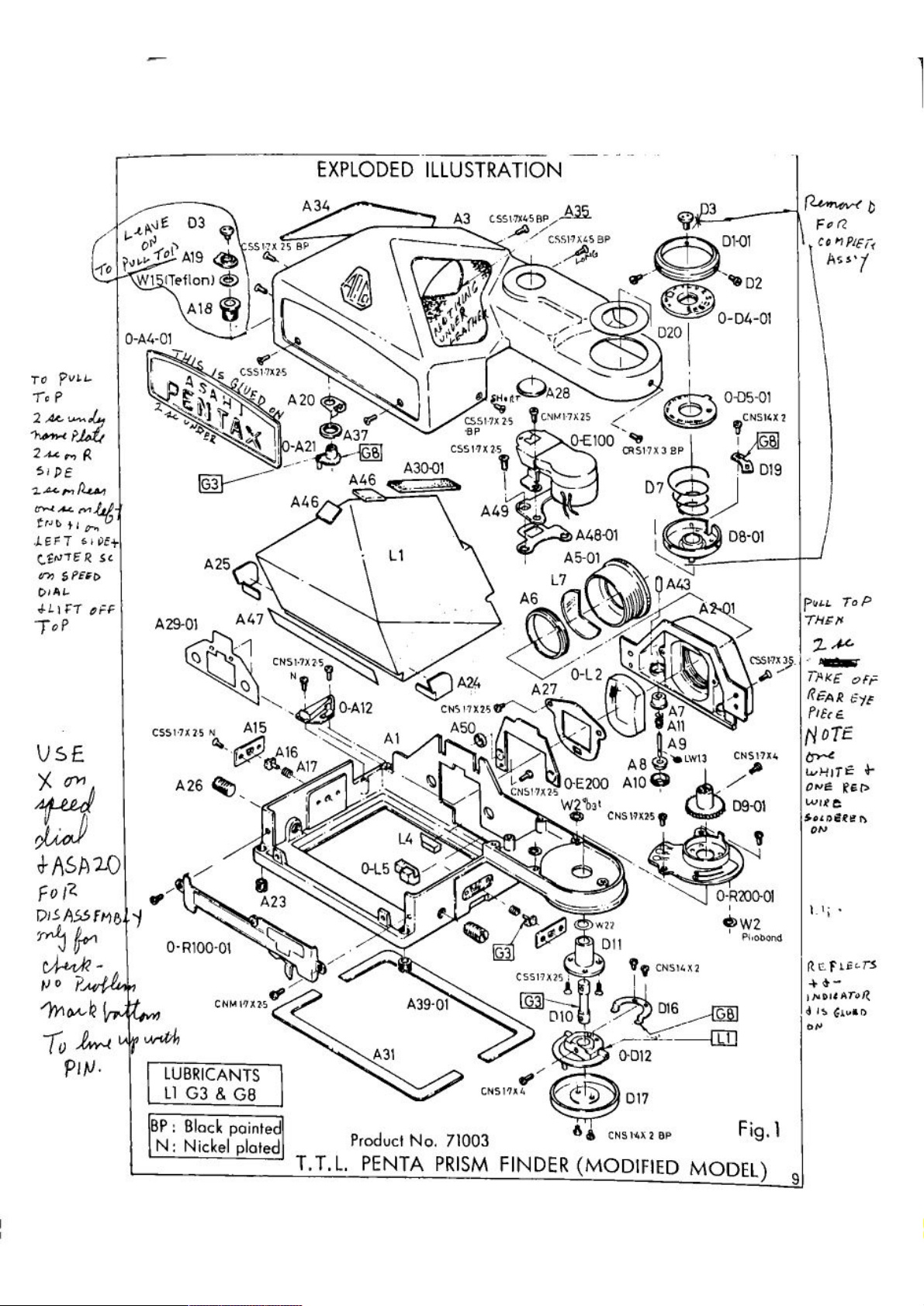
EXPLODED
A34
5P
\V 5
ILLUSTRATION
A3
..
A.» \
A20 I \)
csswx 2,5
A3
A46 ‘-' '
CN51-7X215 /“
Nv fl
0-A12
'\\,
A16 \ I I 'I ‘
~/,1 ‘ Q
,6 , u ‘ _ w
©A24
A1 ASOQI
'BP 1
csswxzfifi ?
1‘ . (
cws117xzsv’\ " Q I
W \ , ' Q
. ' N ,
» 2 -- s
M 1‘
TIM/A10 /
2 " ~ 3’
F“ v x
DIS/‘ISSFMB
r ‘ ' _
"‘13 I“
‘f » 1
042100-01 \
A23
W“ t 1’ -
1” P
’I’VIMI?
14’”
T0
PW'
CNMszs
«‘4, 7‘"
LUBRICANTS
LI
G3
8.
0/ A
GB
O—LS
/. _
\\ '
L4 § \ Q \
%/ \ \ g 0
/égj \ 0 \
“I“ /"
5.
a”!
if
ABS-01
A31
GE
csm-vxe-sap/Als— 9 3
./
cssmcsap
/& (
we
,.
D101
“b
\\,
$1”
A49
\'\\- W
\_//’./ 020
A28
CNMI-szs / /
'7'
)/ “
\\ -
04300
.0-04-01
0-05-01
9CNSIsz
CR2I-7XJBP
D7 J
sir ‘ l /
A4801 1@
A5-01
L7
A6 \‘ I A 1
\‘\l
UA43
// \
08-01
NB 7’45"
‘t ‘
0-L2
A27
/Q
ammo-E200
W$b3I
.2
‘1 V
A3 6
A10 .
CNSI-szsg
\:\ \ A
:1; I N
3.qu
cnsmg 6"“
i/
09 0‘
,3
i.\
'x. , y
‘w
“5”“
\i./ .
ka¢
c5517)“;
y/
Own
10
QB” ‘
99
is I
DIO '
//
AAA—-
(gt?
.K,
0012
017
CNsuxz
DIE/{151E
O-R’ZOO-OI
¢>W2
Phobond
02
(351-719;. «
W
FvQ b
“an5;
Aw;
FULL
Top
1/“
“HIV
TFKE
on:
REAR .-
DYE
PIE(£
DTE
WHITE 3-
one
Rep
59122325
0N
1.1;-
REFUL“
mma
GLqu
:Ilf
BF:
N:
BIOCI‘
Nickel
POWECI
plated
T.T.L.
Producl
PENTA
No. 71003
PRISM
FINDER
55
CNSMX2 BP
(MODIFIED
Fig-I
MODEL)9
Page 4
A
[.5
_J
Lu
r---—------------------------------------v
l : D
I
I 5
Q l I
: U : g
: E 3'
l
III.—
39
It, 0
1‘87 2
:m 8
1'3
I:
i 8 : ‘ a,
I ,
' I
I I I;
I : z D
I I I Z
l
I
I m
I ._ N g
l o
I
‘
:
' U D .
E .
< l I
II ’
_______. | —
\\\ N 1
c:
to“
NA ‘ ‘
CC
a: ' I
O I S ‘ '
it i .
'0. 2
|.E v
a:
:5
UJ
LI_
:58:
'WKE
Z
II
“If
82
13L“
9G.
a.
_3
, .
I:
Q i . *_
E ' I _
I m
<( I I
.E
5 : :
:I: ' J
U
m 3
(2---- o
L--.
o“:— oq—— o o o o o 0 i
8 2
52 r 1 .
" '
.
Lama
l
4
'UI' '
3:
’1: I' m U)
6:") ‘
’élo -
g: :
.@I J
ZL--—--—-—~—-—----- w I
"——-~---—----I I m I g
h—
‘0’ E
‘3' a .
I / \ I
8. ."’ .-
‘rl I I Q
ooea~o L---—---- 'g, 2
:r- 7 g
.. l__________, O '—
an ‘ '
lO-OOlH-O
1,. ,’ 8 L; g
MSW a 2
'r “ ’ : 3 2
IN C
L--¥-~I’--—"\I
IN I . M
‘es/
aA-d
0/! >
1/ a v
I
II C
....|._§ :
€319 :
LP 3
:%‘
‘0
:(S
___l . a,
a.
u.8
'9
I?)
~:
.4
<5
Page 5

LIST
OF
SERVICE
PARTS
Produc?
T.T.L.
1.
The
Parts
Al
A2«01
A3
0-A4-01
A5-l
A6
A7
A8
No.
PENTA
parts
No.
71003 '
PRISM
with
numbers
Prism
seat
Eyepiece h
Top c
Nameplate
over
(A4,
Eyepiece
Eyepiece
Terminal
Terminal
FINDER
starting
Description
(Frame)
ousing
A44)
ring V
lens
insulation
insulation
(MODIFIED
retainer
tube,
collar
"0-"
ring
MODEL)
are
assembled
parts.
Quantity
l
1
l
l
1
l
2
Z
Inter
70034-134
70034-P15
70034-P16
changeab
ility
A9
A10
All
O—AIZ
A15
A16
A17
A18
A19
A20
0~A21
A23
Terminal
Terminal
Terminal
Main
SW
(A12,
Lock
pin
Lock
pin
Lock
pin
Main
SW
SW
handle
Click
Click
spring
plate assembly
(A21, A22,
Viewfinder
contact
nut v‘
spring
seat
A13,
guide
Spring
tub e
guide
A.
assembly
A14,
A32.
A36)
rec
A33.
eptacle
A3
8x3)
2
2
2
1
2 ‘
Z
2
1
1
l
l
2
71002-F27
71003
Page 6

Parts
No.
Description
Quantity
Interchangeability
A24
A25
A26
A27
A28
AZ9-01
A30-01
A31
A34
A35
A37
A39-01
A46
Prism
Prism
Prism
Lens
Meter
Prism
Prism
Prism
Covering
Covering
Main
Prism
Prism
protector A
protector B
retainer
retainer
window
protector
protector
cushion A
screw
plate
sheet,
cushion.
right
left
nut
tube
SW
cushion B :
protector cushion,
rear
large
‘7 “ ‘ '
small
1
1
Z
70034-P8
70034—P7
70034-1310
l
l
1
1
70034-Pl9
l
1
l
l
l
Z.
A47
A48-01
A49
A50
Dl-Ol
D2
D3
0-D4-01
0-D5-01
D7
D8-01
D9-01
Prism protector
mask
Gate
Meter
CdS collar
Shutter dial
Dial
Dial
Dial
ASA dial
installation
installing
retainer
plate
(D4, D18)
(D5,
spring
Dial
Dividing
Dividing
assembly
aaaembly
CNS
D6,
claw
gear
sheet,
screw
screw
1.23:1.4)
plate
front
l
1
I
l
1
3
2
23102-05100
l
l
l
l
l
2/5
71003
Page 7

Parts
D10
No.
Dial
Description
shaft
Quantity
l
Interchangeability
D11
0-D12
D16
D17
D19
D20
O-EIOO
O-E‘ZOO
0-E300
0—E400
E21
L1
D—LZ
L4
O-LS
L7
O-RIOO-Ol
O-RZOO-Ol
shaft receptacle
Dial
Bottom
(D12,
dial
D13,
receptacle
Connector plate
Dial
bottom cover
T-VR
Duster
positioner
ring
Ammeter
CdS
cell
assembly
(FZXZ, E3)
Mia-reading
Metering
C.
board
avoidance
circuit
attaching
Pentaprism
Eyepiece
(L2.
’
11°
Porlo
(LSxZ,
Protection
labs/assembly
L3)
g". ,,
Prismgwi’” V , 1
prism
L6) ‘
glass ; a
F-VR
(R101
«w
R103,
T-VR
(R201 «J
R207)
D14.
spring
plate
board
assembly
D15)
circuit board
tape
.55
2,1,
R106 A,
R118)
1
1
I
1
1
1
I
l
1
I
5
1
70034-Ll
L
1
1
1
1
l
71003
3/5
Page 8

Product
No.
LIST
71003
OF
STANDARD
PARTS
T.T.L.
De
CSS
PENTA PRISM
scription
1.7x2.5
1.7x3.5
CSS
CSS 1.71:4.5
1.23:1.4
CNS
CNS
1.43:2
CNS
1.7x2.5
CNS
1.7x2.5
CNS
1.7x4
CNM1.7
CR5
xZ.5
1.7x2.0
FINDER
Surface
Black
Nickel
Black
Nickel
Plated
Painted
Black Nickel
”
Black
Black
Painted
Nickel _
”
" '
Black
Nickel
Black
Black
Painted
H
II
H
H
Plated
Nickel;
H
H
I!
Painted
(MODIFIED
‘ ,, ._ A
N
I
MODEL)
Position of Use
D11,
A1
A15,
A1
A3, A1
A48,
A49,
Al,
A2
A3.
A2,
A1
0—D5
D8
D19.
D16,
D12
D17,
D12
A12,
A1
R200.
A27,
A1
A2
El, Al
12,
Al
R100,
E1,
A3.
A1
A49
A1
A1
Quantity
3
4
5
2
2
2
l
2
2
2
1
3
l
l
l
l
1
2
2
l
Description
W2
W15
W22
LW
13
4/5
Material
Phosphor B
Teflon
Phosphor B
Steel
ronze
ronze
Thickness
0. 3mm
0‘
2mm
0. 1mm
71003
Position
R100
A19
D11
A9
of
Use
Quantity
3
1
l
2
Page 9

LIST
OF
SPECIAL
SERVICING
TOOLS
Product
T.T.L.
Des
23400K-A33
No.
PENTA
cription
71003
~A
PRISM
FINDER
6 x 7
(MODIFIED MODEL)
23400K-C95-A “
Adjustable
Spanner
AK3 -
LA
Remark:
No
exclusive
are
tools
/ : é”
' " ’ v
,1 z
r6
5. 2' '
used
m;
5L1
cameras
with
2773
T.
T.
L. FINDER
Position of
D3
A10
A6
Use
n
(1’
_’H;(,\' W
7w
J
, K 3‘15, ‘
,. l ' 1‘
r1 \ ,
71003
.
5/5
Page 10

TTL
PENTA
PRISM
FINDER
(MODIFIED
(Prod.
MODEL)
No.
71003)
MANUAL
1
Penta
TTL
This
metering
the
to
state
cally
metering
the
and
when
camera
where
selected
lens
camera
Mis—metering
circuit
switches
Metering
0
toward "+"
deflected
fully
The
operation,
battery
lower.
(acts
tripped
TTL
life.
Use
are
is
beyond
draws
requiring
Prism
with
used
body.
coupler
the
fitting
upon
be
will
body
will be
like a
wrongly
of
and
position
The
camera's
power
Zero-method
over
3EV
power
minimum
Finder
full-aperture
When
is
enjoyed by
and
checked by
actuated.
3EV
toward "-".
toward
from
power
the
battery
for
used
inoperative,
lenses.
the
®selecting
switch)
type
toward "-“,
”+".
Camera‘s
switch
power
checker
2
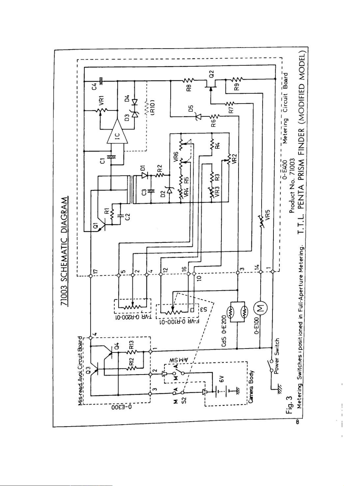
Circuit
General /
resistor
Information
by
D5 to
certain
Calculation
FWVR,
bleeded
the
via.
Most
Field
electronic
from
obtain a
value
takes
T-VR
potential of
Effect
temperature—compensated -——-—-——
For
ponent
repair,
especially
each
CdS
photographic
every lEV
for
place
etc. ,
and
Transistor
components
should be
on
in a
the
the
the
variation
kind
answer
potentiometer
(02).
are
replaced
metering
General
Pentax
Description
6x7
metering
other
with
stop-down
Stop-down
®disengaging
lens‘s
the
indication
When
of
comes
and
the
means
which
with
battery
be
to
for
for
battery
voltage
Description
cells
calculation
(so—called
of a
(the
of
so-called
output
arranged
and a
in a
circuit
camera
lenses
lenses
not
metering
metering
f/stop
preview
incorporated
an
"off"
when
needle
needle
the
and
is
consumes
off
power
turned
normal
check.
”CdS“)
which
input
photographing
of
bridge
this
of
the
is
two
T-VR)
on
mi5~reading
replacement
unit;
basically
board
is
operates
having a
having
the
will
with a
coupling
lever
mis-reading
metering
trips
that
be
will
the
off,
about
after
metering
operation
*1
is
value
subjects.
circuit
calculator
indicated
circuit
avoidance
full-aperture
in
f/stop
coupler
be
coupler
or
automati—
full-aperture
TTL
mode
rests
4mA
to
rated
the
position.
avoidance
selector
ZEV
when
at
for
prolong
5V
4.
between
"Man"
to
about
invisible
needle
is
log-compressed
varies by a
consisting
circuit
ammeter
an
on
boards: a.
of
or
metering
circuit
individual
of
prohibited.
in
from
or
board.
com~
Mienreading
A
power
metering
are
wrongly
closed (that is,
warned by a dead
On normal
switching
When
both
produced,
Automatic
To
voltage
counteract
calculator
~
The
lator
4.
in
5V
calculator AVR
transformer,
avoidance
switching
switches
selected
f/stop
operation in
circuit
comes
switches
modulating
regulator
variation
power
the
source
practical
circuit
circuit
(shown
like
couplings
needle.
are
those
an
is
and
consisting
as
when
82.
SS
A-M
are
whicheither
"ON”
wrongly
with a
closed.
silicon
of
and
switch
engaged).
one
voltage
transistors
Q3.
A—M
of
no
Q4
SW
selected
is
Thus
A-M
switch
drop
forward
into
the
in
any
(voltage
bias
high
"M"
or
shut
to
etc.
(AVR) '
power
the
of
consisting
circuits)
insulated
regulated
output
Ql,
of
consisting
power
7V
6N
to
(BATT).
etc.
Tl
Hybrid
of
source
DC by
two
and a
IC, D3,
obtained
D1 and
power
the
off
schematimdiagram)
being
while
false
82
loss)
Q3
to
impedances.
AVRs
82
metering
closed,
is
less
Q4
and
is
this
than 0.
will be
are provided: a
4-volt regulator
etc. .
D4
from l30Kl—lz oscil-
(Zener
D2
type).
when
1V.
(3. 5 _
1/6
Page 11

r-
Metering
pression
ff
(called a
subjects.
When
output
deflection
Calculator is a
T-VR at
follows
rect
(rheostats)
voltage
receives
speed
Others
As
that
graphing
meter
*1
:3:
.5
.3 ‘
s ‘
:5 By
§
a
Calculation
:7“
Log-compressed
output
unit
Under
E‘V
advances.
voltage
toward
output,
this
high
metering.
as
variation
lEV
are
mechanically
are
electronically
found,
the
developes a
condition. A dual
level.
Logarithmic
VFW
Vb<7¥
3
b
g g . m - u;- "
.
‘a‘
Ti
*2
fll
Apex
Method
One
of
or
subtraction,
being
proper
a
In
this
(1)
evaluated
can
circuit
CdS's
of
which
voltage
variation
usual
rising
(samely
“+”.
voltage—based
and
others.
impedance
Calculator
to
allow
(of
about
mechanical
calculation
certain
Compression
550‘
EV
the
photographic
exposure
Bv'-
unit,
however,
be
re-written
Bv -
information
voltage
against a
brightness,this
when
lowers.
a.
calculator
calculation
An
calculator as a
circuit
the
potentiometers
lOOmV
movement.
culculated,
processed
is
to
find
reference
rheostat
Informfiation
ance
brightness
according
brightness
proportional
is
equally
operating
standard
This
method.s1gmf1cantly
dynamic
in
each
is
Av +
Av +
calculation
Brightness
Apex
defined
Sv -
Sv
and
as
follows:
T'v = o
f/atop,
in
is
varies by
output
output)
ultimate
adjustment
as
given
As
the
result
according
an
adequate
gate
voltage
(VR6)
,7; 3 J
variations)
taking
coverted
varies
lens
enables
range.
Pentax
Numbers
in
the
TV 2 0
Tv
are
fed
into
the
calculator
about
unit
Note
bridge,
high
F-VR
previously)
in
is
from'
of
to
and- K
advantage
into a
range
ES.
methods,attained
(EV),
following
(needle'n
100mV
EV
variation)
level
will
that
with
grows
lower
consisting
input
impedance
should
and
Pentax
being
"‘2Apex
to
impedance
T—VR
SP,
reflected on
degree
of
the
provided
CdS
varies
photographing
the
equation
is a
which
voltage
of
from
ASA
circuit
Sarrie
film
Av,
equation
constant ,
of
reducmg
speed
Bv,
indication)
ZEV
to
against
and
the
as
per a
of
be
around
advancing
resulting
buffer
be
so
made by
to
when
F-VR
shutter
method.
of
voltage
FET
under a
to
establish
resistor
over
wide
subjects
B=KZEV
varies by
Log-compression,
variation
unit
EV
EVl9
100
film)
to
operate
idea
has
through
and
SV
and
in
mechanicallyprocessed.
as a
log-com-
IEV
variation
photographing
1V,
falling
EV, the
in a
needle
of
F-VR
at input,
element,
to
ensure
resistors
produce a unit
or
T-VR
speed
cells
and
T-VR
level
setting.
shift
given
(imped- .
range
since
varies
Where B
showing B
powers
which
variation
to
EVZ. 5
or
its
operating
been
shutter
Tv
the
over
(with
beyond.
with
Apex
employed
only
addition
speed
respectively.
Zero-method.
-------(1)
Equation
(2)
FE‘T
cor-
film
photo—
is
is
of
this
EV.
2/6
Page 12

[A]
Parts:
3
Notice
For
Servicing
mailingpf
E400
in FigS— 1,
operating
E200
Mmgterm~E100 )
Install
within
be so
QdSW-E‘ZOOI
has a
color
and
charactristics.
and
E400
E100
the
fixed
so
metering
as
marking of
E200
should
Installation
that
not
to
RED l
YELLOW l
BLUE I
0-5400
“5 3'“
3eplacement
Dial
to
secure
Ensure
in
Fig3-3)
Installation
(0-E‘400 ) ~ 6’
plate
Of
5200“”
of
ASA
position
T-VR
that
when
Metering
T-VR’s
WHITE l 7
MATCH'NG
Dial
of
operating
the
Meteri§g_Circuit
and
mRed®Yellow®Blue
has a digit marking of from 1 to
be
used in combination shown
it's
metering-reference-gate
image
vignette
(0—D5-Ol ) - -’~ G T
slider
aboVe
§2ircuit
D5
zone
the
1,2
3.1.
5,6
»'
must
be
range
contact
margin
Board ‘
as
shown in
gate
or 3
or5 @-
or 7 _+
or 8
adjusted
of
from
remains
is
'»
Board
area.
along
ASA32:1/1000
within
set.
(043400)
@White
comes
Fig3—2.
FIG
with a
Shutter
A5A324nooo
at
8,according to
Fig3- l.
in
Gate—Mask
3-2
METERING-REFERENCE-
AE
camera body
down to
the
resistor
speed,
spot
the
right
into the
(A48)
n \ .
'BflMaskmg
by
IMAGE
ASA100:1.
area
bycamera's
set
shown
their
position
should
A48
engaged
(shown
detent.
E400
shown
surface
tain
Metering
(L4, 0-
Cemedine
for
clearance
danger
Wirings
circuit
should
in
Fig3-4 by
adhesive
proper
Image
L5 )
bonding.
of
should
board
be
fixed
clearance
[ransfer
30001-1
Prisms
to
Pentaprism
prism
be
side's
into
the
position ‘ I
use
of
tapes
both-side- -
in
to
order
Top
to
main- A
Cover(A3
). .
-.
7y
Prisms
ASAIOOvI
(adhesive)
should
failure
unsoldered
end. -
can
be
used
have
at
least
to
release
upon
impact. 6‘ ,
at
the
the
F1633
CIRCUIT
lNSTALLATlON
Re R
sistorArea
-
55)
ca“
-. , I
BOARD(O‘E400)
Of
'7;
/
Resisw,
A?“
T-V
F|G3
I.
3/6
Page 13

[Bl
Repair
WW
‘ '
Ensure
that
Preview lever
Power
1
a
Circuit
Camera
See
whether
appears on
terminals,
Metering
b
See
whether
.
ductin
c:
d
e
Ammeter
2
Ammeter
a
Calculator
3
See
. g‘ i . . .
Mis—readmg
(O-E‘300 ) ‘ .
Power
Metering
(0-E400 )
7mV-variation
the
next, 5 _ , . ,
f/stop
is
body
Switch
Check
needle
Circuit
coupling
set
at
Check
the
the
as
shown
Switch
82
Avoxdance
(51 )
Circuit
reaches
makes
Check 7 .
is
Power
made ;
Coupler
Terminals
Auto‘vManual
"Auto”. m"
Vacant
battery
power
of
F—VR
Board
output '
coupler
in
Fig3‘5.
is
con-
Circu1t
"zero~point"
lE‘V
needle
when
deflection.
+6V ‘
UHSWitChed
Ground (—)
about
Mm!” »
+6V"'Manual
OV--~Auto
90mV
is
Preview
(ever
Fig3-5.
applied,
IBV'lfith:
If
power
1
2
Egfidle
the
needle
Wiring
Potential
Use
(
The
0.
3V.
and
V.
Bfili'dlfi"
stays
is
"on".
Check:
Check ‘
volt—meter
needle
will
V‘m
will
V2
checks
4V(3*5~45V)
m >' + s
C)
+
of
EM
invisible
check
between
show
be
3
the
with
found
may
regardless of
calculator
the
high
the
"zero"
around
help
:l l 8 +
E a g I '
CE
.— m
i > m
l
I I ‘
LL T % " E
_ o
circuit
input
to
locate
'I g
'-_.
metering
Circuit.
board
impedancea.
when
FET(QZ)
1V
under
the
02
.4
l»
and
usual
cause.
Vout =
90mV
operation
F-VR
or
higher
gate
receives
brightness,
Vin-
w"zero“
T-VR.
than
(Va-VI)
as
3M0.)
around
say
far
E‘VlZ.
as
the
4/6
Fig3-6
Calculator
Circuit
Check
Page 14

4.
Metering
Calibration
FIG
4-1
/
CORgC' O "
EV
AS -
//
Calibration
CHECK
POINT
FULL~APERTURE
/sh»fier
«' V' ., e - .
@//
T// /
speed
’/)‘
,,/'\Q
V'4
V’figwy
'
‘9‘!”
P y . N
5' @g _
'
.I,\ s /"'
51%" /‘ I
\ . ‘
./ ‘
:lr
Sh i
dial
adap/
it.
camera
is
made
TABLE
with a
6x7
ASAIOO
METERING
/VR3f/stop
[\~ ' a
"\- /
(g//
/ '
and
{3
\K
,/
standard
STOP-DOWN
Power
miniature
maybe
clip
turn
on
R2
stop-down
stopdown
For
TTLunitmust
ing
once
be
ed.
lens
METERING
switch
alligator
used
switch.
the
dismount-
fitted.
FIG
to
meter
4-2
_IIIflfl
SHUTTER _ _
Resistors
Full-aperture
VR3
VR4 (
VR6
Stop-down
VRZ
NOTE:
tablished by
Do
to
MIEII
Iflfifll
adjusted:
be
metering
(Rheoatat)
’/ )
(Dual
metering
(Potentiometer)
touch
not
other
than
rheostat)
ofiher
factory
VRs.
f/atop
Shutter
Meter
(also
Matar
since
service.
IEIII
Mall
III-
if/stop-errornimposed
“
calculation
speed
leveling ,
effective
leveling
their
re-settings
adjustment
ASA o
and
atop—down
in
will
reading
metering's
be
not
)
es-
5l6
Page 15

CAUTION
the
to
Due
quent
adgustments.
circuit
. ' e
propert '
The followmg
Y,
an
adjustment
steps
will induc ' ‘
should
carefully
be
vanatlo '
ob::rl:e:ihe
subae-
Adj‘lstrnent
Ensure
1
the
2. Turn
3
Check
a
b 9
(2
Match
4
adjusting
Check
5
a If
b ,,
c
Step4 and 5
6
FULL-APERTURE
steps:
that
f/stop
camera;the
the
on
metering
1
2
3
4
If readings
the needle to
VR6. ‘
the reading at
is
it
'I
(First
how
preview
power
indications
at
E‘Vlé
E‘VB
Ev12
EV4
are
'1
high (+),
low (-),
right
on,
application
it
develops
should be
METERING
coupling
switch.
is
lever is
in the
with
properly made
set at "Auto“.
following
f/S ;
{/8 ;
r/z. 8 ;
s/z. 8 ;
evenly high (+), adjust
low (~), }
scattered,
perform
the ”zero"at
EVS with
f/S ;
increase VR4,
decrease
skip
to
Step '7‘ ’ ’
should be so made to a
the
result .) ' ‘
repeated
until
metering
the following
EV16
with
1/4.
and
see
’/ 3 v
an adequate
sequence.
1/1000
1/4
1/500
1/2
{/8
Step 6.
between
sec.
VR6 to
level.
;1/1000
small
adjustment
TTL
the
recover a
steps.
sec. by
extent
as
unit and
correct
find
to
has been
made.
Check at EVIZ and EV4
7
a H
b
c 9
Return
8
ment
Establish a
9
10
Adjustment
Ensure
1
”Man I“
Perform
2
3
6/6
the
two
readings
’1
(Adjustment
difference may exist
to
Step 4,
has
been
made. ‘
correct metering
Check
Establish a
shown
(
steps:
Small
at
each
STOP
that
only
-DOWN
f/stop
after a
correct
in
Table,
difference at
error )
can
and
check
coupling
metering
Fig4—2 .
with
{/2.
8;1/500
are
high (+),
10w (-),
on, skip to
right
be made in
the
between the two
repeat Step 4 and
level by adjusting
point
shown in
METERING
is
disengaged :
full—aperture
metering
le‘vel, by
each
check
point
and
f/Z. 8 ;l/2
increase
VRB,
and see Step 8.
decrease 2»
Step
9.
same manner
readings
Step
7.
Table,
Fig4—2 .
the
adjustment
adjusting VRZ, at
exist
may
as
as an
until an
VR
6.
preview lever
within
respectively.
in Step
5. A
error )
adequate
is set at
has been made.
the
check points
an
allowable
small
adjust-
 Loading...