

Page 1
Non-Programmable Thermostats
The T8775A,C Thermostats provide single-stage
temperature control for 24V systems. The
T8775A,C models include a thermostat, wallplate
(for wiring and mounting thermostat), mounting
screws, wall anchors, and a 4074 FAB resistor.
MERCURY NOTICE
If this control is replacing a control that
contains mercury in a sealed tube, do not
place your old control in the trash.
Contact your local waste management
authority for instructions regarding
recycling and the proper disposal of an old
control containing mercury in a sealed
tube.
INSTALLATION
When Installing this Product…
1. Read these instructions carefully. Failure to
follow them could damage the product or
cause a hazardous condition.
2. Check the ratings given in the instructions
and on the product to make sure the product
is suitable for your application.
3. Installer must be a trained, experienced service technician.
4. After installation is complete, check out product operation as provided in these instructions.
CAUTION
Electrical Shock or Equipment Damage
Hazard.
Can shock individuals or short
equipment circuitry.
Disconnect power supply before
installation.
® U.S. Registered Trademark
Copyright © 2003 Honeywell International Inc.
All Rights Reserved
T8775A,C
The Digital Round
INSTALLATION INSTRUCTIONS
Location
Install the thermostat about 5 ft (1.5m) above the
floor in an area with good air circulation at average
temperature. Do not install the thermostat where it
can be affected by:
— drafts or dead spots behind doors and in
corners.
— hot or cold air from ducts.
— radiant heat from the sun or appliances.
— concealed pipes and chimneys.
— unheated (uncooled) areas such as an outside
wall behind the thermostat.
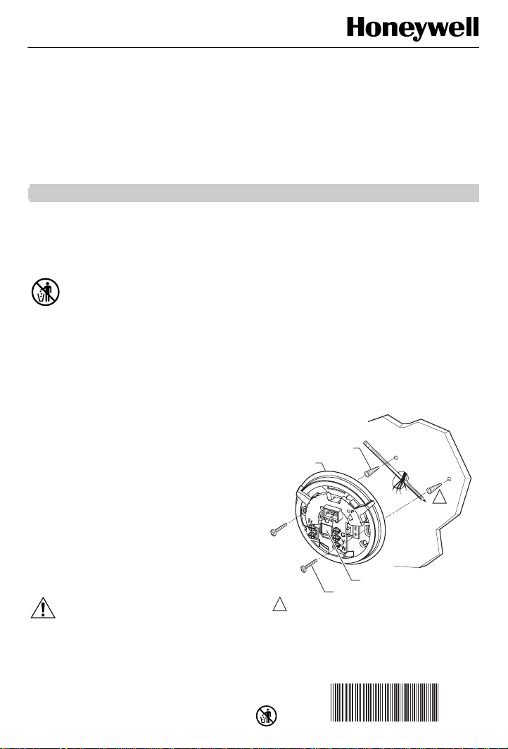
Mounting Wallplate to Wall
Mount the T8775A,C wallplate, with the screws
provided. See Fig. 1.
WALL ANCHORS (2)
WALL PLATE
WIRING HOLE
1 INCH SCREW (2)
1 WHEN USING WALL ANCHORS, DRILL 3/16 IN. HOLES
FOR DRYWALL, 7/32 IN. HOLES FOR PLASTER.
Fig. 1. Mounting wallplate to wall.
69-1677EF
™
1
M19499
Page 2

T8775A,C THE DIGITAL ROUND™ NON-PROGRAMMABLE THERMOSTATS
S
3
4
S
5
S
7
6
Y.
Wiring
IMPORTANT
Use 18-gauge wire to wire the T8775A,C
Thermostats.
All wiring must comply with local electrical codes
and ordinances. Disconnect the power supply to
prevent electrical shock or equipment damage.
Refer to Fig. 2 through 6 for typical wiring hookups.
R
W
1
Fig. 4. Typical hookup of T8775C in heat-cool system
O
Rc
2
R
HEATING
RELAY OR
VALVE COIL
1 POWER SUPPLY. PROVIDE DISCONNECT MEAN
AND OVERLOAD PROTECTION AS REQUIRED.
2 FACTORY INSTALLED JUMPER.
with single transformer.
B
G
Y
W
COMPRESSOR
CONTACTOR
FAN
RELAY
M1951
1
1
POWER SUPPLY. PROVIDE DISCONNECT MEAN
AND OVERLOAD PROTECTION AS REQUIRED.
HEATING
RELAY OR
VALVE COIL
M1951
Fig. 2. Typical hookup of T8775A in a heat-only system.
O
B
Rc
2
G
Y
R
W
1
1 POWER SUPPLY. PROVIDE DISCONNECT MEAN
AND OVERLOAD PROTECTION AS REQUIRED.
2 FACTORY INSTALLED JUMPER.
Fig. 3. Typical hookup of T8775C in heat-only system
HEATING
RELAY OR
VALVE COIL
with fan.
69-1677EF 2
FAN
RELAY
M1951
B
Rc
G
2
Y
R
W
COMPRESSOR
CONTACTOR
HEATING
RELAY OR
1
VALVE COIL
1 POWER SUPPLY. PROVIDE DISCONNECT MEANS
AND OVERLOAD PROTECTION AS REQUIRED.
REMOVE FACTORY INSTALLED JUMPER BETWEEN R AND RC.
2
Fig. 5. Typical hookup of T8775C in heat-cool system
1
Fig. 6. Typical hookup of T8775C in single-stage heat
with two transformers.
4
O
B
Rc
G
2
Y
3
R
W
COMPRESSOR
CONTACTOR
RELAY
1 POWER SUPPLY. PROVIDE DISCONNECT MEANS
AND OVERLOAD PROTECTION AS REQUIRED.
2 FACTORY INSTALLED JUMPER.
3 USE A JUMPER WIRE (NOT SUPPLIED) TO CONNECT W TO
4 USE EITHER O OR B FOR HEAT PUMP CHANGEOVER.
pump system.
CHANGEOVER
FAN
RELAY
HEAT
VALVE
FAN
COOL
CHANGEOVER
VALVE
1
M1951
M1951
Page 3
T8775A,C THE DIGITAL ROUND™ NON-PROGRAMMABLE THERMOSTATS
7
CUSTOMIZE THERMOSTAT
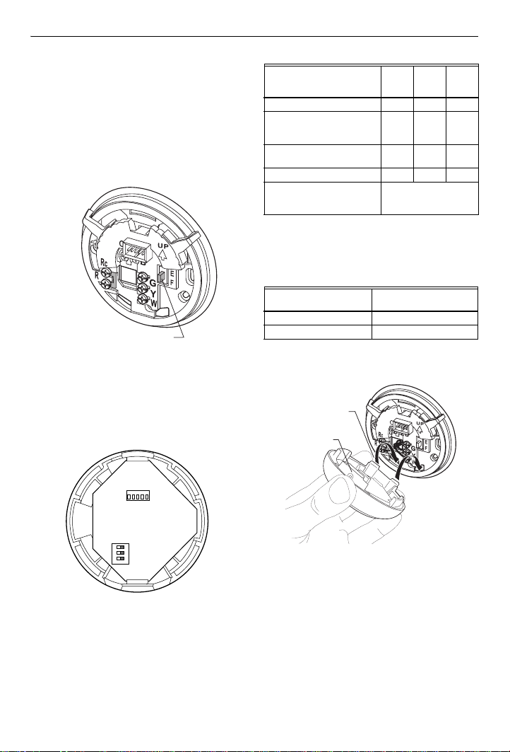
Setting Fuel Switch (T8775C only)
The fuel switch is preset at the factory in the F
position. See Fig. 7. This is the correct setting for gas
or oil systems. If the T8775C is being installed on an
electric heat system, or a heat pump, set the switch to
the E position. The E setting allows the fan to turn on
immediately with the heating equipment in a system
where the G terminal is connected.
FUEL SWITCH
Fig. 7. Fuel switch.
DIP Switch
To adjust the heat cycle rate or the Fahrenheit/Celsius
indication, locate DIP switch 1, 2 and 3 on the back of
the thermostat. See Fig. 8.
M1949
Table 1. Heat Cycle Rate.
Cycles
DIP
Switch
1
DIP
Switch
2
Heating System
Steam, Gravity 1 On On
High Efficiency Warm Air
(90%+ efficiency), Hot Water,
Heat Pump
Gas or Oil Warm Air (factory
setting)
Electric Warm Air 9 On Off
In Floor Radiant Heat Check with manufacturer
Per
Hour
3OffOn
6OffOff
for recommended cycle
rate.
Fahrenheit/Celsius Indication
Use DIP switch 3 to set the desired temperature
indication. See Table 2.
Table 2. Temperature Indication.
Fahrenheit/Celsius
Display DIP Switch 3
Fahrenheit (factory setting) Off
Celsius On
Mounting Thermostat to Wallplate
ENGAGE TABS
AT BOTTOM OF
THERMOSTAT
AND WALL PLATE.
PRESS UPPER
EDGE OF CASE
TO LATCH
1 2 3
ON
M19567
Fig. 8. DIP switch.
Set Heat Cycle Rate
Use DIP switches 1 and 2 to set the heat cycle rate.
See Table 1.
M19498
Fig. 9. Mounting thermostat to wallplate.
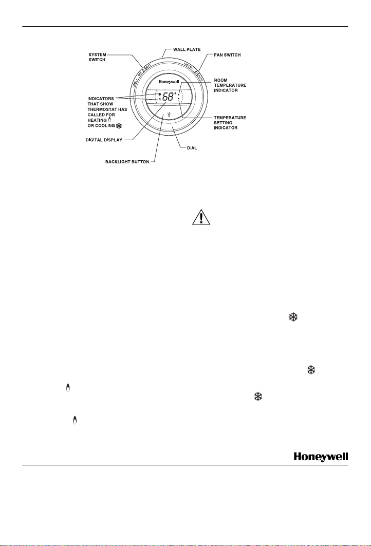
OPERATION
Setting SYSTEM and FAN Switches
(T8775C only)
System and fan settings are controlled manually by
using the switches located at the top of the
thermostat. See Fig. 10.
3 69-1677EF
Page 4
T8775A,C THE DIGITAL ROUND™ NON-PROGRAMMABLE THERMOSTATS
0
BACKLIGHT ON
(T8775C ONLY)
(T8775C ONLY)
SELECTS
COOL/OFF/HEAT
DISPLAYS ROOM
OR SET TEMPERATURE
SELECTS
ON/AUTO
ROOM
SHOWS THAT THE
SET
CURRENT ROOM
TEMPERATURE IS
DISPLAYED.
SHOWS THAT THE
CURRENT TEMPERATURE
SETPOINT IS DISPLAYED.
DISPLAYS AND ADJUSTS
TEMPERATURE SETPOINT/TURNS
Fig. 10. T8775 Thermostat (features and operation).
SYSTEM Switch
Heat: The thermostat controls the heating
system.
Off: Both heating and cooling systems are off.
Cool: The thermostat
system.
controls the cooling
FAN Switch
Auto: The fan only runs with the heating and
cooling system.
On: The fan runs continuously. Use for
improved air circulation.
CHECKOUT
NOTE: Temperature setpoint range is 40°F to 90°F
(4°C to 32°C) in heating and 45°F to 99°F
(7°C to 37°C) in cooling.
Heating
1. Slide the SYSTEM switch to Heat and the FAN
switch to Auto (T8775C only).
2. Raise the temperature setpoint several degrees
above the room temperature.
3. A flame will appear in the display and the
heat should turn on.
4. Lower the temperature setpoint below the room
temperature.
5. The flame will disappear from the display
and the heat should turn off.
Cooling (T8775C only)
CAUTION
Low Temperature Hazard.
Operating at too low of an outdoor
temperature may cause compressor
damage.
Do not operate cooling if outdoor temperature
is below 50°F (10°C). Refer to manufacturer’s
recommendations.
NOTE: If a call for cooling is made before the com-
pressor has been off for five minutes, or if a
power interruption occurs while the compressor is running, the thermostat will go
into a five-minute delay to protect the compressor. The snowflake will flash during
this delay.
1. Slide the SYSTEM switch to Cool and the FAN
switch to Auto.
2. Lower the temperature setpoint several
degrees below the room temperature.
3. After approximately five minutes, the thermostat will display a solid snowflake and the
cooling should turn on.
4. Raise the temperature setpoint above the room
temperature.
5. The snowflake will disappear from the display and the cooling should turn off.
Fan
1. Slide the SYSTEM switch to Off and the FAN
switch to On. The fan should run continuously.
2. Slide the FAN switch to Auto. The fan should
turn off.
M1952
Automation and Control Solutions
Honeywell International Inc. Honeywell Limited-Honeywell Limitée
1985 Douglas Drive North 35 Dynamic Drive
Golden Valley, MN 55422 Scarborough, Ontario
69-1677EF J.S. 6-03 Printed in Hungary www.honeywell.com/yourhome
M1V 4Z9
Page 5

Thermostats ronds numériques,
non programmables
The Digital Round
Les thermostats T8775A et C assurent la
régulation de la température dans les systèmes
24 V à un étage. Ils comprennent un thermostat,
une plaque de commutation (pour le câblage et le
montage du thermostat), des vis de montage, des
chevilles d'ancrage et une résistance 4074 FAB.
AVIS DE RECYCLAGE
Si le présent thermostat remplace un
thermostat contenant du mercure dans une
ampoule scellée, ne pas jeter l'ancien
thermostat à la poubelle.
Communiquer avec le service
d'enlèvement des déchets de la
municipalité pour savoir comment recycler
ce type de thermostat et comment en
disposer.
INSTALLATION
Avant d'installer ce produit…
1. Lire attentivement les présentes instructions.
Le fait de ne pas les suivre pourrait constituer un danger ou endommager le produit.
2. Vérifier les caractéristiques nominales spécifiées dans les instructions et celles indiquées
sur le produit pour s'assurer que celui-ci convient à l'usage prévu.
3. L'installateur doit être un technicien d'expérience ayant reçu une formation pertinente.
4. Une fois l'installation terminée, vérifier le
fonctionnement du produit en suivant les
présentes instructions.
™
T8775A, C
NOTICE D'INSTALLATION
MISE EN GARDE
Risque de choc électrique ou de
dommages matériels.
Peut causer des blessures par choc
électrique ou provoquer un courtcircuit.
Couper l'alimentation avant d'installer ce
produit.
Choix de l'emplacement
Installer le thermostat à environ 1,5 m (5 pi) audessus du plancher dans un endroit où la
circulation de l'air est bonne et la température est
moyenne.
Ne pas installer le thermostat dans un endroit où
les conditions suivantes peuvent nuire à son bon™
fonctionnement :
— courants d'air ou zones sans circulation d'air
derrière les portes et dans les coins
— air chaud ou froid provenant des gaines
— chaleur radiante du soleil ou des appareils
ménagers
— tuyaux et cheminées dissimulés
— endroits non chauffés (ou non refroidis), p. ex.
mur extérieur à l'arrière du thermostat
Montage de la plaque de
commutation
Utiliser les vis fournies pour monter la plaque de
commutation du T8775 A ou C. Voir la Fig. 1.
® Marque de commerce déposée aux É.-U.
Copyright © 2003 Honeywell International Inc.
Tous droits réservés
69-1677EF
Page 6

THERMOSTATS RONDS NUMÉRIQUES, NON PROGRAMMABLES THE DIGITAL ROUND™ T8775A, C
9
3
4
CHEVILLES D'ANCRAGE (2)
PLAQUE DE
COMMUTATION
1
TROU DE CÂBLAGE
1
DANS LE CAS D'UNE INSTALLATION AVEC
CHEVILLES D'ANCRAGE, PERCER DES TROUS
DE 3/16 PO SI LE MUR EST EN PLACOPLTRE OU
DE 7/32, SI LE MUR EST EN PLTRE.
VIS 1 PO (2)
MF1949
Fig. 1. Montage de la plaque de commutation.
Câblage
IMPORTANT
Utiliser un fil de calibre 18 pour effectuer
le câblage des thermostats T8775A et C.
Le câblage doit être conforme aux codes
d'électricité et aux règlements locaux. Couper
l'alimentation afin de prévenir les risques de choc
électrique ou de dommages matériels.
Voir aux Fig. 2 à 6 les schémas de raccordement
typiques.
R
W
O
B
Rc
2
G
Y
R
W
RELAIS DE
CHAUFFAGE OU
1
1 ALIMENTATION. FOURNIR AU BESOIN UN
DISPOSITIF DE COUPURE ET UNE PROTECTION
CONTRE LES SURCHARGES.
2 CAVALIER INSTALLÉ EN USINE
Fig. 3. Raccordement typique du T8775C dans un
système de chauffage seulement avec ventilateur.
1
1 ALIMENTATION. FOURNIR AU BESOIN UN
DISPOSITIF DE COUPURE ET UNE PROTECTION
CONTRE LES SURCHARGES.
2 CAVALIER INSTALLÉ EN USINE
Fig. 4. Raccordement typique du T8775C dans un
système de chauffage-refroidissement avec un
BOBINE DE VANNE
O
B
Rc
2
G
Y
R
W
RELAIS DE
CHAUFFAGE OU
BOBINE DE VANNE
seul transformateur.
RELAIS DU
VENTILATEUR
VENTILATEUR
CONTACTEUR
DU
COMPRESSEUR
M1951
RELAIS DU
MF19515
1
1
ALIMENTATION. FOURNIR AU BESOIN UN
DISPOSITIF DE COUPURE ET UNE PROTECTION
CONTRE LES SURCHARGES.
Fig. 2. Raccordement typique du T8775A dans un
système de chauffage seulement.
69-1677EF 2
RELAIS DE
CHAUFFAGE OU
BOBINE DE VANNE
MF1951
Page 7

THERMOSTATS RONDS NUMÉRIQUES, NON PROGRAMMABLES THE DIGITAL ROUND™ T8775A, C
7
T
MF19516
S
RÉGLAGE DU THERMOSTAT
EN FONCTION DE
B
Rc
G
2
Y
R
W
CONTACTEUR DU
COMPRESSEUR
RELAIS DE
CHAUFFAGE OU
1
BOBINE DE VANNE
1 ALIMENTATION. FOURNIR AU BESOIN UN DISPOSITIF DE
COUPURE ET UNE PROTECTION CONTRE LES SURCHARGES.
ENLEVER LE CAVALIER INSTALLÉ EN USINE ENTRE R ET RC.
2
Fig. 5. Raccordement typique du T8775C dans un
système de chauffage-refroidissement avec deux
transformateurs.
4
O
B
Rc
2
R
RELAIS DE
VENTILATEUR
G
Y
3
W
1
MF1951
L'APPLICATION
Réglage du sélecteur de type
d'énergie (T8775C seulement).
Le sélecteur de type d'énergie est réglé en usine à
la position F. Voir la Fig. 7. C'est le bon réglage
pour les systèmes au gaz ou au mazout. Si le
T8775C est installé sur un système de chauffage
électrique ou une pompe à chaleur, régler le
sélecteur à E. S'il est réglé à E, le ventilateur se
mettra en marche en même temps que l'appareil
de chauffage si la borne G est connectée.
RELAIS DU
VANNE
D'INVERSION
DU CHAUFFAGE
CONTACTEUR DU
COMPRESSEUR
1
1 ALIMENTATION. FOURNIR AU BESOIN UN
DISPOSITIF DE COUPURE ET UNE PROTECTION
CONTRE LES SURCHARGES.
2 CAVALIER INSTALLÉ EN USINE
3 UTILISER UN CAVALIER (NON FOURNI) POUR
RACCORDER W ET Y.
4 UTILISER O OU B POUR L'INVERSION DE LA
POMPE À CHALEUR.
Fig. 6. Raccordement typique du T8775C dans une
pompe à chaleur à un étage.
VENTILATEUR
VANNE
D'INVERSION DU
REFROIDISSEMEN
ÉLECTEUR DE TYPE D'ÉNERGIE
MF19497
Fig. 7. Sélecteur de type d'énergie.
Microrupteurs
Régler les cycles de chauffage ou l'affichage de la
température en degrés Celsius ou Fahrenheit à
l'aide des microrupteurs 1, 2 3 au dos du
thermostat. Voir la Fig. 8.
3 69-1677EF
Page 8

THERMOSTATS RONDS NUMÉRIQUES, NON PROGRAMMABLES THE DIGITAL ROUND™ T8775A, C
RENTRER LES PATTES DE
L
D
L
D
D
A
P
D
F
Tableau 2. Affichage de la température.
Affichage en Celsius ou
Fahrenheit Microrupteur 3
Fahrenheit (réglé en usine) Off
Celsius On
Montage du thermostat sur une
plaque de commutation
1 2 3
ON
A PARTIE INFÉRIEURE
M19567
Fig. 8. Microrupteurs.
Réglage des cycles de chauffage
Régler les cycles de chauffage à l'aide des
microrupteurs 1 et 2. Voir le Tableau 1.
Tableau 1. Cycles de chauffage.
Cycles
Micro-
Système de
chauffage
par
heure
Vapeur, gravité 1 On On
Air chaud haute
efficacité (efficacité
90 %+), eau chaude,
pompe à chaleur
Air chaud au gaz ou
mazout (réglage en
usine)
3OffOn
6OffOff
Air chaud, électrique 9 On Off
Chaleur rayonnante
dans les planchers
Vérifier les cycles
recommandés auprès du
fabricant.
Réglage en degrés Celsius ou Fahrenheit
Choisir l'affichage de température désiré à l'aide
du microrupteur 3. Voir le Tableau 2.
rupteur
1
Micro-
rupteur
2
U THERMOSTAT DANS
ES OUVERTURES
E LA PLAQUE
E COMMUTATION.
PPUYER SUR LA
ARTIE SUPÉRIEURE
U BOÎTIER POUR LES
IXER EN PLACE.
MF19498
Fig. 9. Montage du thermostat sur une plaque
de commutation.
FONCTIONNEMENT
Réglage des sélecteurs du système et du
ventilateur (T8775C seulement).
Le réglage du fonctionnement du système et du
ventilateur se fait manuellement à l'aide des
sélecteurs situés dans la partie supérieure du
thermostat. Voir la Fig. 10.
69-1677EF 4
Page 9

THERMOSTATS RONDS NUMÉRIQUES, NON PROGRAMMABLES THE DIGITAL ROUND™ T8775A, C
A
T
O
)
T
L
MF19520
(T8775C SEULEMENT)
SÉLECTION DE
COOL, OFF OU HEAT
FFICHAGE DE LA
EMPÉRATURE AMBIANTE
U DU POINT DE CONSIGNE
Fig. 10. Thermostat T8775 (caractéristiques et fonctionnement).
Sélecteur du système
Heat : Le thermostat commande le système de
chauffage.
Off : Les systèmes de chauffage et de
refroidissement sont arrêtés.
Cool : Le thermostat commande le système de
refroidissement.
Sélecteur du ventilateur
Auto : Le ventilateur fonctionne seulement
lorsque le système de chauffage et de
refroidissement est en marche.
On : Le ventilateur fonctionne de façon con-
tinue. Ce réglage assure une meilleure
circulation de l'air.
VÉRIFICATION
REMARQUE : En mode chauffage, la gamme de
Chauffage
1. Déplacer le sélecteur du système à Heat et
2. Régler le point de consigne de la tempéra-
3. Une flamme apparaîtra et le système de
point de consigne est de 4 °C à
32 °C (40 °F à 90 °F) et en mode
refroidissement, de 7°C à 37 °C
(45 °F à 99 °F).
le sélecteur du ventilateur à Auto (T8775C
seulement).
ture quelques degrés au-dessus de la
température ambiante.
chauffage devrait se mettre en marche.
(T8775C SEULEMENT
SÉLECTION DE
ON OU AUTO
ROOM
INDIQUE QUE LA
SET
TEMPÉRATURE
AMBIANTE
ACTUELLE EST
AFFICHÉE.
INDIQUE QUE LE POIN
DE CONSIGNE ACTUE
DE LA TEMPÉRATURE
EST AFFICHÉ.
AFFICHAGE ET RÉGLAGE
DU POINT DE CONSIGNE
OU RÉTROÉCLAIRAGE
4. Régler le point de consigne de la température quelques degrés au-dessous de la
température ambiante.
5. La flamme disparaîtra et le système de
chauffage devrait arrêter.
Refroidissement (T8775C seulement)
MISE EN GARDE
Risque dû aux basses températures
Le fonctionnement du système de
refroidissement lorsque la température
extérieure est trop basse peut
endommager le compresseur.
Ne pas faire fonctionner le système en
mode refroidissement si la température
extérieure est inférieure à 10 °C (50 °F).
Lire les recommandations du fabricant.
REMARQUE : Si un appel de refroidissement est
1. Déplacer le sélecteur du système à Cool et
2. Régler le point de consigne quelques degrés
5 69-1677EF
effectué moins de cinq minutes
après l'arrêt du compresseur ou s'il
y a coupure d'alimentation lorsque
le compresseur est en marche, le
thermostat passera en mode temporisation pendant cinq minutes.
Cette temporisation a bout but de
protéger le compresseur. L'icône
flocon de neige clignotera pendant ce délai.
le sélecteur du ventilateur à Auto.
au-dessous de la température ambiante.
Page 10

THERMOSTATS RONDS NUMÉRIQUES, NON PROGRAMMABLES THE DIGITAL ROUND™ T8775A, C
3. Au bout de cinq minutes environ, un flocon
de neige apparaîtra sur le thermostat. Le
système de refroidissement devrait se mettre
en marche.
4. Régler le point de consigne à une température supérieure à la température ambiante.
5. Le flocon de neige disparaîtra et le
système de refroidissement devrait arrêter.
Ventilateur
1. Déplacer le sélecteur du système à Off et le
sélecteur du ventilateur à On. Le ventilateur
devrait fonctionner de façon continue.
2. Déplacer le sélecteur du ventilateur à Auto.
Le ventilateur devrait arrêter.
69-1677EF 6
Page 11

7 69-1677EF
Page 12

Solutions de régulation et d'automatisation
Honeywell International Inc. Honeywell Limited-Honeywell Limitée
1985 Douglas Drive North 35, Dynamic Drive
Golden Valley, MN 55422 Scarborough (Ontario)
M1V 4Z9
69-1677EF J.S. 6-03 Imprimè au Hungary www.honeywell.com/yourhome
 Loading...