

Page 1
GPS::L=
'Y
t-
GPS Unit
-
PS1
iJem~a}j~
Operating Manual
:::
O)t~1fI~,
";'
17
'/
!J
A '
GPS:l
.:::
'/
r O-GPS1
1t
s
..
, '.11
1,
'tet::
"'''-'1:<1'>
')
b11::.
:;
~<O',
';1',.
;;j;:jj\\I~,
!-OilL
Il'lli', /lilli',
UTe
(W,:¥1!!WHi!),
1H'r
1
lUIl1t"
;,
17
'/
!J
A T
')
17
!kl:J !-71:
ic£'~,
-8
t~""o)
7
!J
i!
-tt')
-c'"
:::
O)ilI'!!l
IDlaJHI,I;I:,
,,,'I'Il'S;;j;:ill'
iJio-¥
1l'".ill-ClllP.lt
2'
'
nc,';I".
~liI'!!lO)MI:,
:::O)ilI'!!l~aJl;!11tJ:<
s",
&O):;:t,
IE
L,
< sill',' <
t::2',
'.
Thank
you
for
purchasing
the PENTAX GPS Unit
O-GPS1.
This
GPS
unit
is
a camera accessory
for
PENTAX
digital
cameras
to
record
location information
,
such
as
latitude,
longitude,
altitude, Coordinated
Universal Time
(UTe)
,
and
orientation.
This
operating
manual
is
divided
in
two
parts:
The first
part
is
in
Japanese
and
the
second
in
English.
Please
read this
operating
manual
carefully
first
for
proper
use
.
Page 2
GPS Unit
-
PS1
Operating Manual
Page 3
Regarding a
Trademark
PENTAX is a trademark
of
HOYA
CORPORATION.
Illustrations
and
Terminology
In
some illustrations in this manual, the PENTAX
K-S
is used
as
an example, and operations are
explained on the assumption that the four-way
controller is used to select a menu item and the
OK
button is used to determine the se lection.
Function names differ depending on the camera.
For details, refer to the operating manual
of
your
camera.
FOR THE SAFE USE OF YOUR
GPS UNIT
Although
we
have carefully produced this GPS unit
for safe operation , please take special note
of
the
following:
& WARNING
This symbol indicates that violating this item could
cause serious personal injuries.
& CAUTION
This symbol indicates that violating this item could
cause minor
or
medium personal injuries,
or
loss
of
property.
& WARNING
• Do not attempt to disassemble this GPS unit
yourself.
& CAUTION
• The following may lead to an explosion or fire.
• Shorting a battery
• Exposing a battery to flames
• Disassembling a battery
• Attempting to recharge a non-rechargeable
battery
Precautions
for
Your
GPS
Unit
• Never use organic solvents such as thinner,
alcohol or benzine to clean this GPS unit.
Page 4
Contents
Name s
of Parts
..........
.......................................
...
2
Sp
ecifications ................................................... 19
Features
of
the O-GPS1 ...................................... 3
Supported Cameras
...
................. '
...
....................... 3
Notes
on
the
GPS Un
it
........................................
20
El
ectr
onic
C::ompass
............................................
20
Ti
me .......................
.............................................
21
Getting Started .
......
..........................
...........
......
..
4
Inserting the Batt
ery .................... "
...
" .................... 4
warranty
Policy ...................
.. ..
.........................
22
Mounti
ng
the GPS Unit on the Came ra ...............
..
6
Turning
the
GPS
Unit
On/Off ...............................
..
7
Calibration
...........................................
.................
..
8
Using the GPS Function .............
......
.................. 9
Display
ing
the Electro
nic
Compass
.....................
11
Using the Simple Navigation Function .........
...
12
Selecting
the Des
tination
and Dis
playing
the
L
ocation
Informatio
n .....................................
12
Managi
ng the
Destina
tio
n I
nformation .......
...
.. .....
12
Using the ASTROTRACER Function .......
...
.. ..
. 16
Using Other
Functions
........................
...
...
......
..
18
Setting the
Positioning Interval
..................
...
....... 18
A
djusti
ng
lhe Dale a
nd
Time Automal
ical1y .......
..
18
1
Page 5
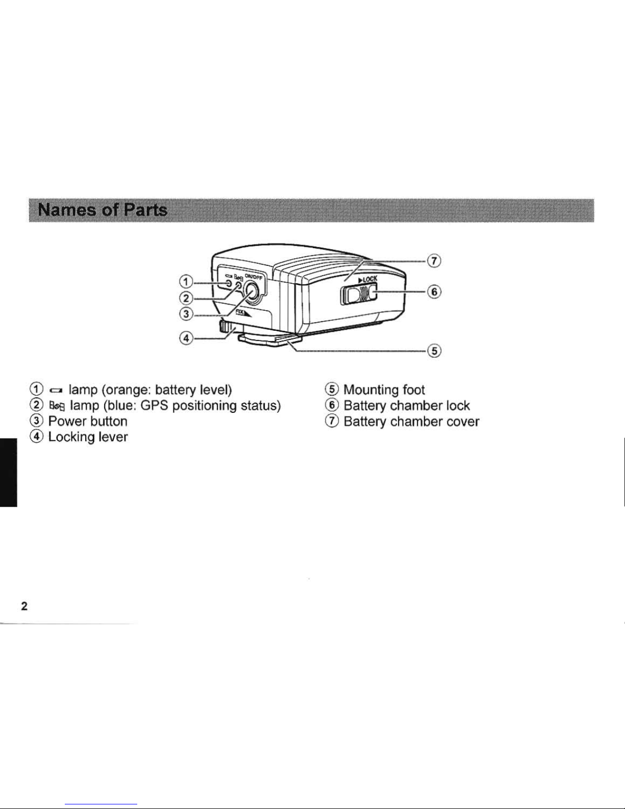
2
CD
= lamp (orange: battery level)
®
80s
lamp (blue: GPS positioning status)
®
Power
button
@ Locki ng lever
® Mounting foot
® Battery
chamber
lock
CD
Battery chamber cover
Page 6
F"eature$
olthe O-GPS1
• Information can be
sent
to the camera by
attaching the O-GPS1 unit to the camera's
hot shoe.
• Designed with dust-proofness and water-
resistance
in
mind.
• Features an electronic compass .
• Features the Simple Navigation function,
which shows the distance to the destination.
• Features the ASTROTRACER function
(a
built-in equatorial mount) , which is convenient
when taking pictures
of
stars .
•
Supported
Cameras
The
PENTAX
K-S,
K-r
,
and
6450
support this GPS unit (as
of
May
2011).
Before using this unit with
the
above-
mentioned three models, however , you need
to update the firmware of your camera. The
firmware supporting GPS can be down loaded
from the following website:
http://www.pentax.jp/j a p a
nl prod
uctsl 0-g ps
11
For details about the compatibility
of
cameras
released
in
May 2011
or
later, refer to the
operating manua l
of
the camera or visit our
website.
• When the firmware
of
your camera is updated to
a version supporting this GPS unit, new items
are added to the shooting menu and/or
playback mode palette, and the order
of
items
changes accordingly.
• This GPS unit and a flash cannot be used
at
the
same time. When using this GPS unit, always
attach it to the camera.
• While shooting with Live View, the Electronic
Compass and Simple Navigation functions are
disabled ,
• The ASTROTRACER function cannot be used
with the
645D
. For detailS about the
compatibility
of
cameras released
in
May 2011
Of
later, refer to the operating manual
of
the
tamera
or visit our website.
• The maximum trace duration with the
ASTROTRACER function varies depending on
: the shooting conditions.
3
Page 7
4
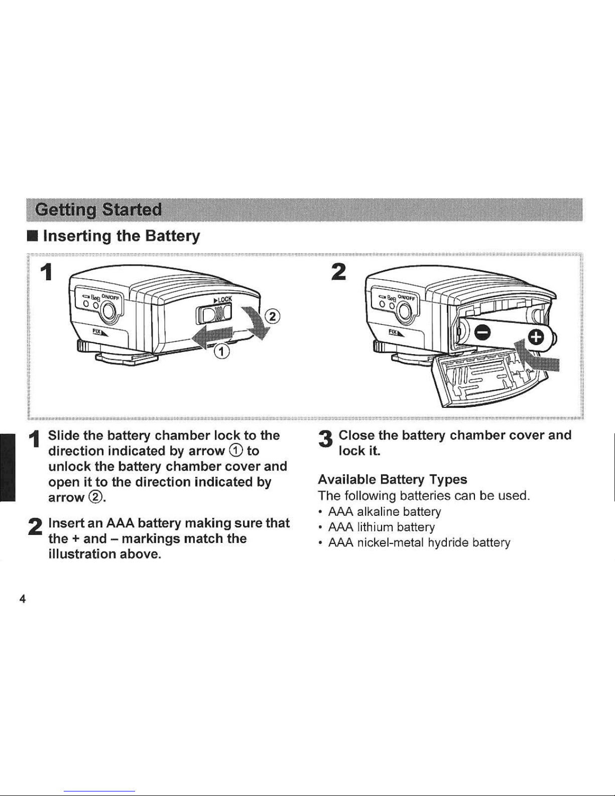
• Inserting the Battery
!
!
i
""
1
Slide
the
battery
chamber
lock
to
the
direction
indicated
by
arrow
CD
to
unlock
the
battery
chamber
cover
and
open
it
to
the
direction
indicated
by
arrow
®.
2
Insert
an
AAA
battery
making
sure
that
the
+ and -
markings
match
the
illustration above.
3
Close
the
battery
chamber
cover
and
lock
it.
Available
Battery Types
The following batteries can be used.
•
AM
alkaline battery
•
AAA
lithium battery
•
AM
nickel-metal hydride battery
Page 8
-
~...
. .... .
--.
.,
...
.
•
5
Page 9
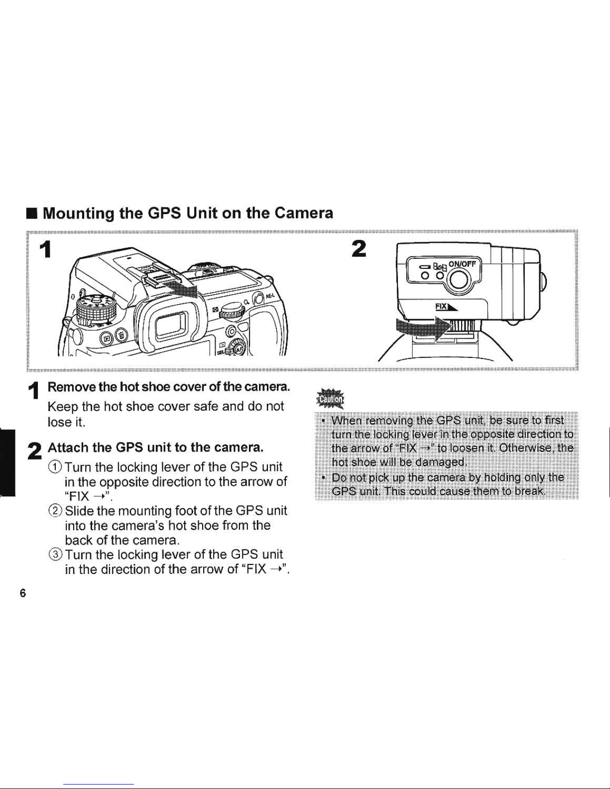
• Mounting the GPS Unit on the Camera
J 1 .
;;
.,
, .
""","".1"""
:
.»:,,::::
'"
@"';';
"m""'''~-'~2-~''''''''''''''''''''''"S
Wi""
._ow
""-
""
1 Remove the
hot
shoe
cover
01
the
camera.
Keep the hot shoe cover sale and do not
lose it.
6
2
Attach
the
GPS
unit
to
the
camera.
CD
Turn the locking lever
olthe
GPS unit
in the opposite direction to the arrow
01
"FIX
-t".
@Slidethe
mounting
loot
olthe
GPS unit
into the camera's hot shoe Irom the
back
01
the camera,
® Turn the locking lever
01
the GPS unit
in the direction
01
the arrow
of
"FIX -->",
Page 10

•
Turning
the
GPS
Unit
On/Off
.~.--
..
'''''
.....
•
• •
7 7
•
•
-,
•
•
•
•
•
•
•
,
• ,
I
•
,
0
I
•
,
I
,
I
80s
,
(blue)
t
.....
".-
...
•
,
,
"'",n2W"
1 Press
and
hold
the
power button
for
one second.
The GPS unit turns
on
and the
80s
lamp
lights up or blinks (depending on the
positioning statu
s),
2 To
turn
the
power
off, press
and
hold
the
power
button
for
one
second
again
.
•
,
1
I
!
"
,
-,
,
il
-,
,
0'
~
J
• Wh
en
the battery is
com
pletely exha usted, the
~
lamp' does not illuminate. When the battery
is
runn i
ng
lOW,
the
c:;::II
lamp blinks as follows, In
.
this
conditi'on,
replace
the
battery wi,
th
a
new
or
"
i;!
f
ull
y-char
ged one.
,57
H'
,
"
:~'
..
When the,
exp
osu
re' metering
timer'df
the .
".
::.
camera is,
off:
, Blinks every 3.seconds
-
When
Jhe
e)::posure metering timer
of
the
l:a1l)9:fa is on: Blinks every 2 seconds
• The functions which '
employ
GPS (Electronic
, Compass! Simple Nav (gation aod •
i'
ASTROTRACERl are not enable,d wben the
camera.is turned off, or
when
the·camera
's
Auto
, power
Qff
function
is
actIVated
.
l
~
you
want
to
" .
.,"
..
.
::,.,
use
th.e
Ele.~ronlc
Compass
or
Simp
le
d;'
';;
:::I~
Navigatlon function"'
cOl')tiOu,ously
',
canbel.the
.
....
, . . .
ii~i'
.csr1
era
's
AU!Rf9
;~.~~~~
Rf!
.run.ctfo
"
n
in
adv~n?e.
7
Page 11

•
Calibration
Calibration is the operation to get the
electronic com
pa
ss to work accurately.
Always perform this before using the GPS
unit.
As the Earth's magneti c field varies
depending on the shooting location, precise
calibration must also be performed at each
location when shooting images
of
astronomical objec ts with the
ASTROTRACER function,
1
Attach
the
GPS
unit
to
the
camera,
and
then
turn
on
both
the
GPS
unit
and the
camera.
8
2
Select
[Calibration]
from
[GPS]
in
the
[01 Rec, Mode]
menu
on
the
camera,
l Move
the
camera
and
perform
the
calibration.
Hold the camera firmly and rotate the
camera
180
degrees or more in each
of
three directions as shown on the right.
• Time
allowed forcalibration
is
one minute. If
you
cannot finish the calibration within a minlJte
or
tne message [The operation could
not
be
"
!;
completed
corr~ctlYl
is displayed on the 'camera
::
g monitor
1
face the
c~rnera
.
in a diffe[eJlfdjrecti8[:l
~
:;:
and
try
the cali
bration again.
:i!
r· Be careful
not
to
drop
the
camera' while
~l
, performing the calibration.
:l
•
Always
perform the calibratJon when
~pew
Of
;;
futly·cha,rged
battery is installed, Qr when the"
i:!
GPS unit1s removed
from
the, camera
~l';'lcfJhen
,
i
...
-
--
..
. ,
_
!!!t~~;M
O!
again.
·;::~!.._:!!mH!
!;:;;:!
,
Page 12

I
_.
__
t
... _ ....
~:=
.
=.
=:":.~"="~'~":
:-
---
.
...,
i I
...
I
t
I
~h
I
r
~
L
....
7
__
~
,
___
'la
:
,
:':
"_
~
~
_.
I
~
_.
e
_
)
________
",,.1
1
Attach
the
GPS
unit
to
the
camera, and
then turn
on
both
the
GPS
unit
and
the
camera.
After the power is turned on, the
80s
lamp
blinks while positioning by GPS and then
stays illuminated after the GPS
positioning
is
carried
out.
The GPS icon will
be
displayed
on
the
status screen on the camera monit
or.
9
Page 13

a.alamp
Blinks
Lights
Lights
10
&s
lamp and GPS icons
GPS
icon
Status
~
(Red)
GPS
data
cannot
be
obtai
ned
.
Three
satellites
are
dete
cted and
GPS
~
(Yellow)
data
can
be
obtained;
the
GPS
data
is
r
ecorded
to
an
image
when
shooting
.
Four
or
more
satellites
are
detected
and
~
(Green)
more
precise
GPS
data
can
be obtained
:
the
GPS
data
is
recorded
to
an
image
when
shooting
.
2 Take a
picture.
The current location information will be
recorded to the image.
• For the movies, GPS data cannot
be
recorded.
3 Play
back
the
image and
check
the
GPS data.
For details on how to play back images,
refer to the operating manual
of
the
camera
.
Page 14

•
Displaying
the
Electronic
Compass
The electronic compass can be displayed on
the camera
monitor
.
1
Select
[Electronic
Compass)
from
[GPS)
in
the
[0
Rec.
Mode)
menu
on
the
camera.
The
electronic
compass
appears on the
camera monitor and the current latitude,
longitude, altitude ,
direction'
, and the
Coordinated Universal Time (UTC) are
displayed.
If
you rotate the camera to
point the lens
in
a different direction, the
face
of
the electronic compass turns.
, On the electronic compass
of
this GPS
unit,
0
0
is based on
True
North, not
Magnetic North. (180
0
is based on
True
South.)
.-
N 35"45.882'
~
(;;;;I
$ E139°41.503'
r\
49m
Iii!
05/0512011
0 10:05:08
re
If
you
op.erate·
Ct""he"""'camera
(SUCh
-
as
changing
the
~
shooting mode) while the electronic compass IS
ij
displayed
on
the camera monitor) the camera
:1
stops displaying the electronic compass.
~
Select [Electronic Compass] from [GPS] in
th~
'j
lORee
, Mode] menu to ,display the electronfc
!:
compass again.
II
.•
~
. ~"-'
.~;"
~
.Hin
, 0
••.••
*hH.
11
Page 15

•
• Selecting the Destination and
Displaying the Location
Information
Direction and distance to the destination
based
on
the current location can
be
displayed.
1
Select
[Simple
Navigation)
from
[GPS)
in
the
[0
Rec. Mode)
menu
on
the
camera.
2
Select
[Select
Destination).
3
Select
the
desired
destination.
4
Select
[Navigation
Start).
12
Direction
(~
mark on the compass face)
and distance to the destination are
displayed. based on the current location.
Ct
PENTAX_Osa
ka
JP
~
c::::J
Current location
;: N 35045.882'
(Ill
E139°41.S03'
r'l
49m
Direction
of Destination
253
·
Distance
to
Dest
ination 10850km
[iil
05/05/2011010:05:08
• Managing the Destination
Information
Destination
information can
be
saved
to
or
deleted from a memory card. The
inf
ormation
saved
on
the memory card can also be
loaded.
1
Select
[Simple
Navigation)
from
[GPS)
in
the
[0
Rec. Mode)
menu
on
the
camera.
2
Select
[Destination
Manager).
Page 16

3
Select
[D+I!!l
Load
from
the
card],
[D>!!! Save
to
the
card],
or
[I~
Delete
destination].
Loading
data
from
the
card/Saving
data
to
the
card
4
Select a file
to
save
the
destination
list
data.
To save the destinalion list data to the
memory card, enter the name
of
the
destination list file (Title Entry) first and
save
it.
tho
Speci
fy
where
to
save
the
destination
list da
ta
lEE
IU.
",
..
13
Page 17

Deleting
the
destination
data
4
Select
destination(s)
to
be deleted.
Press the
OK
button to tick the checkbox
.t.
I
JP
JP
JP
5 Press
the
Wi
button.
6
Select
[Select
& Delete].
14
The selected destination(s) will be
deleted.
'9
""""W_7r'00'rty'
'Wt~W_tW_~WtWWWW
W
"W,WW,",
"W
• •
I:
4
As
tHe destination data
of
the factory default
!!
'
$~ttlng
is deleted jf overwritten, save
it
as
[f
n~ce~sary.
:::
• •
! . To save
the
shootin'g
locl:\tion
of
the
.
L .
«ips
information as ai
destlnation,
play:back
o.
0'
'.
¢ ' i mage and select
[SavE;
Destin~tjon]
;
in
t,
he
"
::111
pfa>,back
mode
palette.
.H
,
."
•••
.
."
."
.
.
".
" ,
•
Page 18

"
;"'""~.
;:f:U
.,.:
">'@_"*'~~'"_,",;:1r"",
"~"~
•
If
you
.operate
th6lp~O'Jere
.
~uch
a~
changIng
the
i
shootmg
mode)
whlle
uslng
the
Simple
A
, . . .
,"M
Na\llg8,tion
funct!po
;;
th-e
camela slops
W'!
, displaying
the
localion
In\Ormafion,
;J
, .
..
.
Seled [Simple
~avjgatiOl1)
from
[GPS)
in
the
;1
[ORee.
Mode)
menu3m:J
start
th&navig8tion
to
"!
<L
~L~e!~y
;
m!=:
J9:9!~
~rng
rm~U¢n
, .
a~~in.
;oJ
15
Page 19

Using
the
ASTROTRACER
Function
When shooting images
of
astronomical objects
with long exposure by using a camera with the
Shake Reduction function, the ASTROTRACER
function enables
you
to track them as the Earth
rotates and make them look like stationary
points of light with
no
trails
in
the images.
1
Set
the
exposure
mode
and
the
focus
mode
of
the
camera
to
Bulb
and
MF
(Manual
focus),
respectively.
Refer to the operating manual
of
the
camera.
2
Select
[ASTROTRACER
(Bulb)]
from
[GPS] in
the
[0
Rec.
Mode]
menu
on
the camera.
16
Max. Trace Duratio n •
~
Timed Exposure 0
Expos ure Time
Preset
Pres lee Calibration
3
Select
[Precise
Calibration].
Hold the camera firmly and rotate the
ca
mera
180
degrees
or
more
in
each
of
three directions as shown below.
4
To
set
the
exposure
time
using
the
timer,
tick
the
checkbox
for
[Timed
Exposure]
and
set
the
time
in
[Exposure
Time
Preset]
.
Set the exposure time (minute/second).
5
Select
[Start
Shooting].
Page 20

6 Set the
focus
and press the
shutter
release
button
.
,
Shooting starts.
When shooting is finished, the
ASTROTRACER setting screen is
displayed again.
•
Whe-n~
using
the
ASTR~OTAAcER
funatio
;'-
itie
~
shutter cannot
b~
released and shooting
will
not
start until the GPS positioning is carried out.
o The maximum trace duration varies depending
on
the
foca
l length, shooting location,
or
direction that the camera faces to. You cannot
I:
settheexposure time longer than the maximum
t trace
dur<iJtion.
i.
' When using a lens without focal length
p information , set the focal length
of
your lens with.
f {lnpulFocal
Length1
in
the
[0
Ree. Mode] menu·
before shooting images
of
astronomical objects.
!.
AlWays
execute
the
precise calibration before
• shooting-images of
astronomical objects.
• When
u~!ngthe
ASTRQTRACER function,
[HQriz;oQCorreGtion] and_
[Composit
ion
AdjustJ
•
of
the camera are
not
enabled .
...
~~~~
-
.........
~..
...
:~=.-
~
"
.-
.---
•
As
the precise calibration performs high-
accuracy calibratio n,
it takes a while to
f:omplete.
•
When
shooting images
of
astronomical objects ,
you
can not use autofocus.
Adjust
the focus
manually .
.
-.
.
-.
.
17
Page 21

• Setting the Positioning Interval
You can set the duration to receive the GPS
data (duration to perform the positioning) .
1
Select
[Positioning
Interval)
from
[GPS)
in
the
[0
Rec. Mode)
menu
on
the camera.
2
Select
[lmin.),
[3min.), [5min.),
or
[10min.).
~
..
".~~
. - -
.••• ~ ....
'. ,'--'_'" ···'w ..
..
"
. '
According
to"·the
.
[Positionin9'1nt~rval)
sefting
,
:J
Ii
metering"operati'n'g, time
of
the
i:arOe'~a
';
i~
h"'!i'
til;
, , .
''''1;
!"'I
,
ex!ended
auto~aticany'
.
,
"
':H
"11
r·
Whe
'n
the
GPS
unit
is
on,
(Meter
Operatin
"g
:1
i
Time]
in
the
(C
Custom
Setting]
menu
is
I
j
.f
dl
splayed
in
g~y
a~d
qannot
be
s
~~~
ed
.
18
• Adjusting the Date and Time
Automatically
After turning the camera on, the date and
time
of
the camera are updated according to
the signal (2D
or
3D) first received from the
GPS unit.
1
Select
[Auto
Time
Synch.)
from
[GPS)
in
the
[0
Rec.
Mode)
menu
on
the
camera.
2
Tick
the
checkbox
et.
Page 22

Product name
Type
Supported camera
Recorded information
Receiving function
Acquisition time
Positioning interval
GPS accuracy
Data format
Geodesics
Electronic compass
Dimensions
Weight
Power
source
Battery life
PENTAX GPS Unit O-GPS1
Clip-on GPS unit
K-S
.
K-r
. and
(as
of
May 2011)
Latitude, longitude , altitude, time
(UTe),
direction
Tracking channels: 50. supports SBAS (WAAS/EGNOSIMSAS)
Cold-start: approx.
40
seconds, hot-start approx . 5 seconds
1 second
10
m RMS
NMEA-0183
World Geodetic System
(WGS
84)
Accuracy: ±5° (precise calibration), positioning interval: approx. a times, reference
direction: True North
Approx
. 49.0 mm (W) x 33.0
mm
(H) x 59.5
mm
(D)
Approx .
61
9 (including alkaline battery), approx.
50
9 (unit only)
AAA
battery
)(
1 (alkaline battery, nickel-metal hydride battery , or lithium battery)
Continuous operating time:
approx.
7 hours (normal
temp.)/4
hours (0°) with alkaline battery
approx. 7 hours (normal
temp.)/S
hours (0°) with nickeJ..metal hydride battery
approx. 12 hours (normal
temp.)/9
hours (0°) with lithium battery
•
19
Page 23

• Notes
on
the
GPS
Unit
• Local geographic and atmospheric conditions
may prevent
or del
ay
the reception
of
GPS
data . This
GPS
unit
may
be
unable to receive
GPS data indoors, underground,
or
near
large
structures, trees, or other objects that block or
reflect satellite signals.
• The positions
of
GPS satellites are
continuously changing and this may prevent
or
delay
the reception of
GPS
data at certain
hours of the
day
.
• The presence of mobile phones or other
devices that transmit frequencies close to
those
of
GPS
satellites , or magnetized high-
voltage
li
nes may also interfere with the
reception
of
GPS
data.
• Note that this GPS unit may take a whi le to
reacquire a signal if it has not been used for
an
extended period
or
has bee n moved a
great distance from where the
GPS
data
was
last received.
• Turn the
power
off
in
any place where,
or
on
any occasion when the use
of
electronic
20
device is prohibited, such as while visiting a
hospital , or tak ing
off
and landing
of
airplane.
.In
some
cou
ntr
ies or regions, using
GPS
or
collecting positioning data may
be regulated.
When you travel overseas, consult the
embassy or
your
travel agency about using a
camera with a GPS function or collecting the
positioning log data.
• GPS data recorded
in
the image cannot be
deleted. If you
do
not want to get the shooting
location
inf
ormation before the publ ic such
as
a
webs
ite, etc
.,
turn this GPS unit off before
shooting.
•
Electronic
Compass
• If you use this GPS unit near objects which
generate a magnetic field such as magnets,
or have magnetism such as iron, the
electronic compass
may
not work properly.
Page 24

• Time
• The time recorded to images is Coordinated
Universal Time
(UTe). Please note, however,
that when using the Electronic Compass or
Simple Navigation funct ion (when receiving
GPS data), UTC
is
adjusted according to the
time zone
of
the shooting location, and the
adjusted time is displayed on the camera
monitor
.
Hereby, HOYA CORPORATION, declares that
this GPS unit O-GPS1
is
in
compliance with the
essential requirements and other
re
levant
prov
isi
ons
of Directi
ve
1999/5/EC
.
For a full version of the Declaration of Conformity
(DoC), please refer to
http
://www.pentax.jp/eng
lish
/.
•
21
Page 25

All PENTAX camera accessories purchased through authorized bona fide photographic distribution channels are
guaranteed against defects of material or workmanship for a period
of
twelve months from date
of
purchase. Service will
be
rendered, and defective parts will
be replaced without cost to you within that period, provided the equipment does not show
evidence
of
impact, sand or liquid damage, mishandling, tampering, battery
or
chemical corrosion, operation contrary to
operating instructions,
or
modification
by
an unauthorized repair shop. The manufacturer or its authorized representatives
shall not
be
liable for any repair or alterations except those made wi
th
its written consent and shall not
be
liable for damages
from delay or loss
of use
or
from other
ind
irect
or
consequential damages
of
any kind, whether caused
by
defective materi
al
or
workmanship
or
othelWise; and it is expressly agreed that the liability
of
the manufacturer or its representatives under all
guarantees or warranties, whether expressed or implied, is strictly limited to the replacement
of
parts as herein before
provided. No refunds wi
ll
be
made
on
repairs
by
non-authorized PENTAX service facilities.
Procedure During 12-month Warranty Period
Any PENTAX which proves defective during the
12
-month warranty period should be returned to t
he
dealer from whom you
purchased the equipment or to the manufacturer. If there is
no
representative
of
the manufacturer
in
your country, send the
equipment to the manufacturer , with postage prepaid.
In
this case, it will take a considerable le ngth
of
time before the
equipment can
be
returned to you owing to the compl icated customs procedures required. If the equipment is covered
by
warranty, repairs will be made and parts replaced free
of
charge, and the equipment will
be
return
ed
to you upon
completion
of
servicing. If the equipment is not covered by warranty, regular charges
of
the manufacturer or
of
its
representatives will appl
y.
Shipping charges are to be borne by the owner. If your PENTM was purchased outside
of
the
country where you wish to have it serviced duri
ng
the warranty period, regular handling and servicing fees may
be
charged
by the manufacturer's represen tatives in that country. Notwithstanding this, your PENT AX returned to the manufacturer will
be serviced free of charge accordi
ng
to this procedure and warranty policy.
In a
ny
case, however, shippi
ng
charges and customs clearance fees are
to
be borne by the sender. To prove the date
of
your purchase when requ i
red
, please keep the receipts
or
bills covering the purchase
of
your equipment for
at
least a year.
Before sending your equipment for servicing, please make sure that you are sending it to the manufacturer's authorized
representatives or their a
pp
roved repair shops, unless you a
re
sending it directly to t
he manu
facturer.
Always obta in a
quotation for the service charge, and
on
ly after you accept t
he
quot
ed
service charge, instruct the service station to
proceed with the servicing.
22
Page 26

• This warranty policy does not affect the customer's statutory rights.
• The local warranty policies available from PENTAX distributors in some countries can supersede this warranty policy .
Therefore , we recommend that you review the warranty card supplied with your product
at
the time
of
purchase,
or
contact the PENTAX distributor in your country for more information and to receive a copy
of
the warranty policy.
For
customers
in
USA
STATEMENT OF FCC COMPLIANCE
This device complies with Part
15
of
the FCC Rules. Operation is subject to the followi
ng
two conditions: (1) This device
may not cause harmful interference, and (2) this device must accept any interference received , inc luding interference that
may cause undesired operatio n.
Chang
es
or
modifications
not
approved by the party responsible for compliance could void the user's authority to operate
the equ
ip
ment.
This equipment has been tested and found to comply with the limits for a Class B digital device , pursuant to part 15
of
the
FCC Rules.
These limits are des igned to pr
ovide
reasonable protection against harmful interference in a residential installation. This
equipment gene rates , uses and can
rad
iate radio frequency energy and, if not installed and used in accordance with the
instructions, may cause harmful interference to
rad
io communications. However, there is no guarantee that interference
will not occur in a particular installation .
If this
eq
uipment does cause harmful interference to radio
or
television reception, which can be dete rmined
by
turning the
equipment off and on, the user is encouraged to try to correct the interfe rence by one
or
more
of
the followi
ng
measures:
• Reorient
or
relocate the receiving antenna.
Increase the separation between the equipment and receiver.
Connect the equipment into an outlet on a circuit different from that to which the receiver is oonnected .
* Consult the dealer
or
an experienced radiofTV technician f
or
help.
For
customers
in
Canada
This Class B digital apparatus complies with Canadian ICES-003.
Pour
les
utilisateurs
an
Canada
Cel
appareil numerique de la classe
Best
conforme a la norme NMB-003 du Canada.
23
Page 27

HOY A CORPORATION
PENTAXlmaging
Systems
Division
PENTAX
Europe
Imaging Systems
S.
A.S. (European
Headquarters)
PENTAX Imaging Systems GmbH
PENTAX
Imaging
Systems
Limited
PENTAX
Imaging
Company
A
Division
of
PENTAX
of
America,
Inc.
PENTAX Canada Inc.
PENTAX
Trading
(SHANGHAI)
Limited
2-35-7 ,
Maeno
-cha, ltabashi-ku, Tokyo 174-8639 ,
JAPAN
(http://www.pentax .
jp)
112
Quai
de
Bezons, B.P. 204 , 95106 Arg
enteuil Cede
x,
FRAN
CE
(HQ - http://www
.pentax.eu)
(France - http://www .pentax.fr)
Julius-Vosseler-Strasse 104, 22527 Hamburg, GERMANY
PENTAX House, Heron Drive, Langley, Slough, Berks SL3
BPN,
U.K.
( http://www . pentax.
co.
uk)
(Headquarters)
600
12th Street. Suite 300 Golden, Colorado 80401, U.S.A.
(P
ENT
AX
Service Department)
250 North
54t
h Street Chandler, Arizo
na
85226, U.S.A.
(http://www.pentaximaging.com )
1770 A
rgent'a Road Mississauga, Onlario L5N 3S7, CANADA
(http://www.pentax.
ca)
230, Jun
Yao International Plaza, 789 Zhaojiabang
Road, Xu
Hui
District, Shanghai, 200032 CHI
NA
(http://www.penlax.com.cn )
http://www.pentax.jp/english
• Specifications and external dimensions
are
subject
to
change without
no
tice. C
E:
The
CE
Mark
is a
Dir
ective
conformity
mark
of the Eur
opean Union.
58210 Copyrigh1
<C
HOVA
CORPORA
TION 2011
H02·201106 Printed
in
Philippines
Page 28

,
Notification of
Change
In
Company
Name
HOYA
CORPORATION
PENTAX
Imaging
Systems
Div
ision
will
officially be
renamed
PENTAX
RICOH
IMAGING
COMPANY,
LTD,
on
October
1,
2011.
We
will
continue
to
market a fine line of products
under
the
familiar
PENTAX
brand
to
satisfy your
demands and requirements.
We
thank
you
for your cont
inued
support
and
patronage
to
PENTAX
RICOH
IMAGING
COMPANY,
LTD,
and our
PENTAX-brand
products.
Annonce
du
changement
de
nom
de
notre
societe
La societe
HOYA
CORPORATION
PENTAX
Imagi
ng
Systems
Division prendra
Ie
nom
de
PENTAX
RICOH
IMAGING
COMPANY,
LTD.
a partir du 1er octobre
2011.
Suite a notre rachat par la societe
RICOH,
et
afin
de
salisfaire
les
possesseurs d'appareils photo
PENTAX
et conserver
la
notoriete
de
notre
marque depuis
presque
un
siecle,
nos
produits conserveront
Ie
nom
PENTAX,
Nous
tenons
a vous remercier par avance pour votre
fidelite et esperons que
vous
continuerez a faire .
confiance
aPENTAX
RICOH
IMAGING
COMPANY,
LTD,
et
aux
produits
PENTAX,
58252
RO
lOTI11 Printed
in
Philippines
 Loading...