

Page 1

Page 2

[ INDEX ]
Page
[DISASSEMBLY & ASSEMBLY PROCEDURES] .................................................................................2
OUTLINE
COSMETIC PARTS
1.
SOLDERING OF THE MAIN BODY
2.
MAIN P. C. BOARD
3.
MAIN BODY
4.
...........................................................................................................................................2
......................................................................................................................................2
.............................................................................................................3
(0-T100)...................................................................................................................4
...............................................................................................................................................4
* Soldering position of lead wires for Winding motor (0-S200)......................................................4
TOP COVER
5.
(0-A301)...............................................................................................................................5
5-a. Arrangement of the reverse side of the Top cover..................................................................... 5
5-b. Flash case (Q2)................................................................................................................................5
5-c. [Adjustment & Confirmation] Installing position of the Pop-up magnet (G119).....................6
5-d. [Confirmation] Retraction of the Flash..........................................................................................6
DJUSTMENT & CONFIRMATION
6. A
.............................................................................................................6
6-1. Function check..................................................................................................................................6
6-2. Adjustment with the Programmed software.................................................................................. 7
6-3. Position of the Light sensor...........................................................................................................7
[DATA TABLE]..............................................................................................................................................8
BATTERY LIFE
1.
BATTERY CONSUMPTION CURRENT
2.
...........................................................................................................................................8
..........................................................................................................8
[TABLE OF JIGS, TOOLS AND TESTERS] .........................................................................................8
THE TOOL FOR FLASH POP-UP
*
..................................................................................................................9
27550 1/9
Page 3
A
[Disassembly & Assembly procedures]
Outline
The disassembly and assembly procedures of MZ-7 are similar to the MZ-5 and MZ-10.
The only exclusive notice of assembly for MZ-7 is mentioned below.
For others, refer to the Service manual of MZ-5 and MZ-10.
1. Cosmetic parts
[Disassembly procedures]
1-1. Flash pop-up
To remove the top cover, insert the battery and push the flash pop-up button.
In case of the power line of the camera is defected, use the hand-made tool to pop-up the
flash
1-2. Bottom cover (A401), Back cover
7 screws (A181, A187 x6), Battery cover (0-A402)
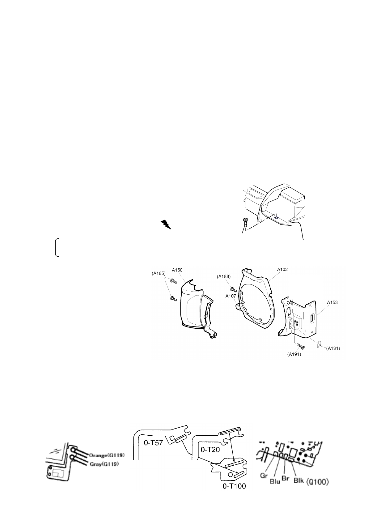
1-3. Top cover (0-A301) and Front cover
1) 8 screws for top cover
A186, A187 x2, A188 x2, A190,
TY-CNL-D 1.7x8.0(Ni), TY-CNL-D1.7x8.0
2) Discharging the Main capacitor
Lift up the top cover slightly and discharge.
The blue lead wire (Xe+) on Flash PCB
The bayonet mount retainer screw (GND)
3) Front cover (A102, A153), Grip (A150)
[Note for assembly]
Set Focus mode lever (A131)
and AF-SW at “AF” position.
186
*In case of replacing A131(=27250-A131),
cut the positioning stud of reverse side
of A131. (Early production model)
4) Unsolder 7 lead wires and 3 FPC (T51, 0-T20, 0-T57) come from
top cover
[Note of assembly]
1) Solder wires and FPC in order of Orange and Yellow (G119), T51, 0-T20, 0-T57,
Black (A330) and lead wires from Q100
2) Arrange lead wires of Q100 (Green, Blue, Brown, and Black) and Black (A330).
(Same as MZ-10)
3)
Install A186 screw before retract the flash.
②
①
2/9 27550
Page 4

2. Soldering of Main body
[Disassembly procedure]
2-1. Switch the panorama lever to “Full frame”
2-2. Remove the LCD….TY-CNL-D1.7x5.0
2-3. Around the release SW (Refer to the figure below)
8 lead wires, 8 soldering lands
[Note of assembly]
Arrange lead wires as below. ( )
DT(3x7)
Blk
(A37)
Red
Ye(C18)
Br(0-S200)
Pu(C18)
R(A35)
2 lands
Gray
(0-Q201)
2-4. Top of the film chamber
[Note of assembly]
Position the FPC at correct place and fix with DT (4x10).
(A36)
2 lands
Pi(0-S200)
4 lands
(I210)
(0-Q201)
DT(10x6)
2-5. Soldering
2 lead wires of N300 (Red and Black, Unsolder at FPC of G100).
Soldering lands : 4 FPC (T81, T301, T61, T64), DX contact (R110)
[Note of assembly] After soldering, put T81 FPC aside of mirror box.
2-6. Base plate (O205)
1) Battery contact piece (-) (A34)
3) TY-CNL-D1.7x4.0, Lift up O205.
2-7. Eyepiece frame (M301)
2 screws
2-8. Main body and Front housing
6 screws, A162
[Note of assembly]
While paying attention to the lead wires and FPC, install the Front housing with the Main body.
The Mechanical back (Standard : 45.46 mm±0.02 (Same as MZ-5)
27550 3/9
Page 5

3. Main P. C. Board (0-T100)
[Note of assembly]
3-1. When the viewfinder LCD is installed,
push the LCD to the direction of allow mark.
(Same as MZ-10)
3-2. Stick the tape (DT, PT and BT) as shown in the figure.
4. Main body
[Note of assembly]
The soldering position of winding motor (0-S200)
The length of the lead wire is different from MZ-5. In case of 0-S200 is replaced, lead wires
should also be replaced.
Pink (65mm) 0-S200
Brown (65mm)
Ground (GND) mark
4/9 27550
Page 6

5. Top cover (0-A301)
[Note of assembly]
When assembling the top cover, refer to the Parts list and figures below.
The type of the Hot shoe cover should be “FK” type for MZ-7. (The other type may activate
the switch (A329) and result the Flash won’t pop-up.)
5-a. Arrangement of the reverse side of top cover
DT (7x10) 0-T57
DT (5x7) 0-T20
DT (4x10) T60
*Arrangement of Q100’s lead wires *Center part of top cover
Black Brown Blue Green (Q100) 0-A368
Bond
5-b. Flash frame (Q2)
Blue
0-A373 0-A365
Gray Orange G119
Apply silicon
(4 points)
Q3 (Adj.)
From top, Green, Brown,
Green Black and Blue
Bond
27550 5/9
Page 7

5-c. [Adjustment & Confirmation] Installing position of Pop-up magnet (G119)
1) At the flash pop-up condition, the armature of G119 should be
positioned as shown in figure right.
2) Loosen Q3 installing screw and tight again. (Refer to figure in front page)
3) At the flash retracted position, when the armature lever (0-A373) is
pushed toward the back and released, the flash should be pop-up.
4) After adjustment and confirmation above, apply screw lock to G119, retainer screw and
2 portion of positioning studs.
5-d. [Confirmation] Retraction of the Flash
Confirm after installing the Flash cover (Q1).
1) At the retracted position, there should be approx. 0.1mm play when Q1 is pushed down
toward as the arrow mark.
2) The flash should not pop-up when the side of Q1 is pushed gently.
[Adjustment]
The choice of thickness or using quantity of Q3
Q3-00A (t=0.2), -00B(t=0.1), -00C(t=0.15)
aa
0-A373
6. Adjustment and confirmation
The adjustment and confirmation as follow are same as MZ-5.
* Exposure and DX code
* AF check (Except Power zoom function)
* Mechanical back (Standard : 45.46 mm ±0.02)
* Mirror function
st
* Position of 1
6-1. Function check
The exclusive function for MZ-7.
1) Set the mode dial at AUTO PICT
When the main switch is turned on, the LED of the mode dial should light up in order as
follow.
→ → → → → → →
2) The LED of the mode dial should correspond as accordingly to the position of the mode dial.
(Continue to next page)
and 2nd mirror
and FA(F) lens at “A” position.
AUTO PICT
6/9 27550
Page 8

3) Remote control mode – Select the mode ( ) by the drive button ( )
The self-timer LED should flash, and the shutter should be released by the transmitter.
4) Set the mode dial at “Tv” and operate the select lever, Tv and Av display should be changed.
The Bar Graph in the viewfinder should be displayed when the Side button is pressed, and
the 1/30 or slower speed should be displayed by orange color. (With FA(F) 50 mm lens)
5) The ISO film speed and PCV Beep tone should be able to selected by the select button at
the “ISO” or ( ) position of the mode dial.
6) At the AUTO PICT
press the shutter button half way, the flash should pop-up automatically and the back light
on the external LCD panel should light up.
At the “AF” mode, cover the front of the lens by hand, and press the shutter button half
way, the flash should be fired continuously to help the focusing.
7) When the flash button ( ) is pressed, the flash should pop-up and the Auto-flash mark
( ) should be off
At the Red-eye reduction mode ( ), the flash should be fired twice.
6-2. Adjustment with the programmed software
27550 programmed soft (Exclusive use)
The other items and the method of connection are same as MZ-5.
mode and MF(AF-SW) mode, cover the front of the lens by hand, and
1) The method of adjustment is same as MZ-5.
2) The positioning of AF frame (Viewfinder) and AF sensor and AF chart are same as MZ-10.
6-3. Position of the Light sensor
1) The method of adjustment is same as MZ-5.
2) The position is a same as MZ-10. (Refer to the figure below)
3.4
AF frame
0.5mm
(
±±±±
0.5mm/actual size
0.0〜+1.0mm
Center of the Light sensor
Center of the AF frame
)
27550 7/9
Page 9

[Data table]
1. Battery life
Condition/Temperature
Without flash Approx. 120 rolls Approx. 30 rolls
With 50% flash Approx. 20 rolls Approx. 15 rolls
With 100% flash Approx. 12 rolls Approx. 5 rolls
Exposure time at the Bulb mode Approx. 8 hours Approx. 2 hours
* 24 exposure roll of film, with new CR2 battery
2. Battery consumption current
Main swittch OFF (Back cover close)
Main Switch ON (Meter Sw OFF)
With FA lens
With F or A or M lens
Meter switch ON
Exposure (Bulb)
AF motor operating (Average)
Rewinding
Without lens
20℃/68°F-10
50μA or less
280μA or less
260μA or less
250μA or less
120 mA or less
150 mA or less
700 mA or less
500 mA or less
℃
/14°F
*With regulated DC power supply, set at 5.5V (More than 3A)
[Jigs, tools and testers]
◎
Exclusice use for 27550
1. Programmed software
PC/AT compatible, 3.5 inch (SD Ver.3.1 or later) No.95901-P274
PC98 (NEC or EPSON) 3.5 inch (ND Ver3.1 or later
PC98 (NEC or EPSON) 5.0 inch (ND Ver3.1 or later) No. -P184
2. Flash pop-up jig (Hand-made)
*To use for pop-up the flash with out power (electricity)
The way of making and dimensions are shown in next page.
◎
Others
Interchangeable with MZ-5. Refer to the Service manual of MZ-5.
)
No. -P084
8/9 27550
Page 10

*Flash pop-up jig
[Material] Telephone-card or equivalent, which can be inserted between flash, cover and top cove
r.
1.The way of making (Size and shape are just for the reference)
1) Cut the card as below. (Fig.1)
2) Cut the corner as below. (Fig.2)
2. How to use
50
40
①②
③④
10
Fig. 1 (Ex.: 4 pcs.
15
)
Fig.2
①
②③
27550 9/9
 Loading...