

PRF-RO

1
PENTAIR REVERSE OSMOSIS SYSTEM
INSTALLATION AND MAINTENANCE MANUAL............................................P.2
SYSTÈME D’OSMOSE INVERSE PENTAIR
MANUEL D’INSTALLATION ET DE MAINTENANCE ...................................P.19
UMKEHROSMOSE-WASSERFILTERANLAGE PENTAIR
EINBAU-UND BETRIEBSANLEITUNG.........................................................P.36
SISTEMA DE ÓSMOSIS INVERSA PENTAIR
MANUAL DE INSTALACIÓN Y MANTENIMIENTO ......................................P.53
SISTEMA AD OSMOSI INVERSA PENTAIR
MANUALE DI INSTALLAZIONE E MANUTENZIONE ..................................P.70
en
fr
de
es
it
PRF-RO

TABLE OF CONTENTS
2
E
N
G
L
I
S
H
1 SAFETY GUIDES P. 3
2 THE BASIC REVERSE OSMOSIS SYSTEM P. 4
3 INSTALLATION P. 10
4 TO CARE FOR THE RO SYSTEM P. 14
5 REPLACEMENT OF THE PREFILTER, POSTFILTER, AND RO
MEMBRANE ELEMENTS P. 15
6 SPECIFICATIONS P. 17
7 TROUBLESHOOTING P. 18
8 INSTALLATION INFORMATION AND INSTRUCTIONS
FOR DRAIN COUPLING, DRAIN-BOA
TM
MODEL DC 9700 P. 87

3
E
N
G
L
I
S
H
1 - SAFETY GUIDES
Read and follow all steps and guides carefully before installing and using your reverse osmosis system.
Do not use this product to make safe drinking water from non-potable water sources. Do not use the system
on microbiologically unsafe water, or water of unknown quality without adequate disinfection before or
after the system.
This reverse osmosis system contains replaceable components (membrane elements). These components
are critical for the effective reduction of total dissolved solids and specific contaminants that are listed in
thep product data sheet.
The reverse osmosis system does not have a monitoring device for contaminants. To verify that the system
is performing satisfactorily the product water should be tested periodically by the system’s installing dealer
or a certified laboratory, every six months. The laboratory should be certified for testing the specific
contaminants of concern. For a listing of certified laboratories, contact local regulatory agencies.
Consult your local public works department for plumbing and sanitation codes. Follow your local codes if
they differ from this manual.
The reverse osmosis system works on water pressures of 2.8 bar (40 psi) minimum to 5.5 bar (80 psi)
maximum. Water pressure can be reduced by installing a pressure reducing valve in the water supply pipe
to the RO system. A booster pump should be used for low pressure applications.
Do not install the reverse osmosis system in extreme hot or cold temperatures. Temperature of the water
supply to the reverse osmosis system must be between 4°C (40°F) and 38°C (100°F). Do not install on hot
water lines.
The reverse osmosis membranes contain a food grade preservative for storage and shipment. All new
membranes require a minimum 2 hour rinse to properly rinse out the preservative. The preservative is not
harmful but makes the product water taste objectionable.
Rinsing the membrane also acts as a performance conditioner. All new membranes will reach their stable
maximum performance after 8 hours of rinsing.

2 - THE BASIC REVERSE OSMOSIS SYSTEM
4
E
N
G
L
I
S
H
Your reverse osmosis system is a water treatment unit. It uses water pressure to reverse a natural physical
process called osmosis. Water, under pressure, is forced through a semi-permeable membrane to filter out
minerals and impurities. Treated drinking water goes to the faucet. Minerals and impurities are sent to the drain
with RO waste water.
The system includes replaceable filters and membrane elements. The prefilter reduces sand, silt, dirt, rust
particles, other sediments, and chlorine from the water supply before they enter the RO membrane elements. The
postfilter reduces any tastes and/or odours that may remain in the water after passing through the RO membrane
elements.
Before installing the RO system
• Best performance of the system will be achieved when the incoming water has been treated (softened).
• The water coming into the system must be within certain limits for sediments, pressure, etc. Refer to the
specifications to determine if your installation is within the limits.
• A water quality analysis can be performed to determine if incoming water requires any treatment. Contact your
dealer/ installer.
• The filters and membrane elements in the RO system need to be replaced on a regular basis. Follow the
instructions for replacement that are in this manual.
NOTE: For optimal system performance, use the system for at least 2 minutes continuously each day.
WARNING: The RO system is designed to work without the aid of a pressurized storage tank. Installation of a
pressurized storage tank will negatively affect system performance.
Tools and materials required
• Adjustable wrench, and larger adjustable jaw pliers or pipe wrench to fit sink
drain
• Saw for cutting drain pipe
• Slotted and Phillips head screwdrivers
• Tubing cutters
• Electric drill and bits for cutting the faucet mounting hole
NOTE: Note that some sinks will have a pre-drilled hole with a plug for the faucet.
5
E
N
G
L
I
S
H
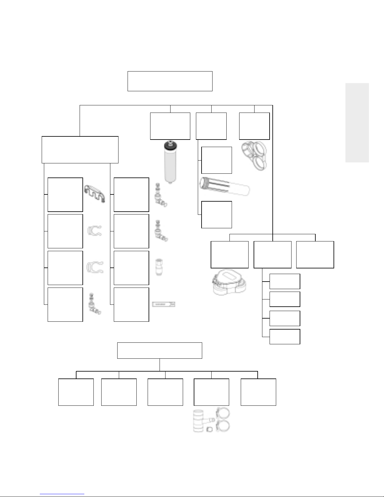
2 - THE BASIC REVERSE OSMOSIS SYSTEM
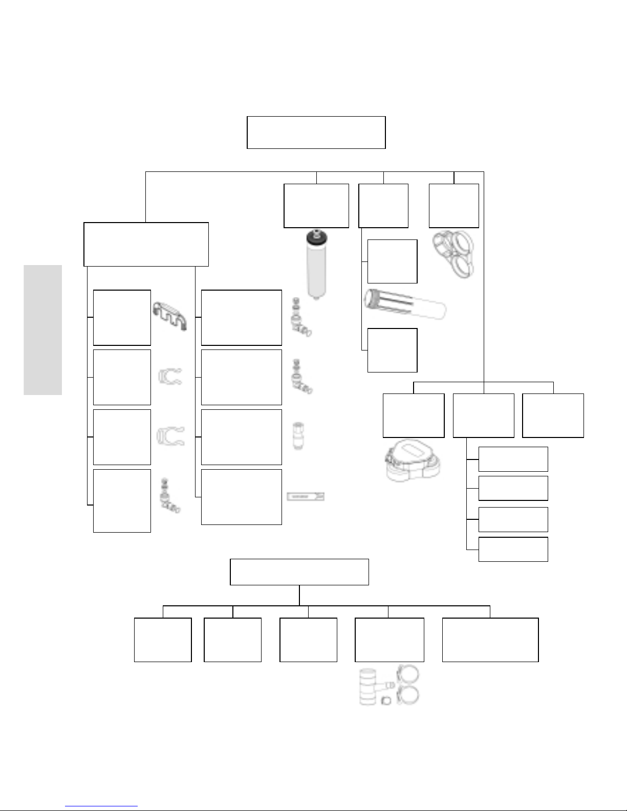
Some configurations may not include
all components listed below
Fittings & locking bar
install kit
PN 4000330
Locking bar
disconnect
PN 3038026
(1 pc)
Feed
disconnect
elbow-white
PN 3035307
(1 pc)
Permeate
disconnect
elbow-blue
PN 3035305
(1 pc)
Faucet
connection
fitting
PN 3038251
(1 pc)
Silicone
lubricant SGL
use tube
PN 1013501
(6 pcs)
3/8“ collet
lock clip
PN 3038239
(5 pcs)
1/2“ collet
lock clip
PN 3038250
(2 pcs)
Drain
disconnect
elbow - black
PN 3035306
(1 pc)
Sump
PN 1239705
(3 pcs)
O-ring
PN 1240326
(3 pcs)
3/8“ black
tubing (4 ft)
3/8“ blue
tubing (4 ft)
1/2“ natural
tubing (4 ft)
1/2“ red
tubing (3 ft)
Complete
manifold
PN 4000445
(1 pc)
Tubing
install kit
PN 1255736
Feed pressure
gauge
PN 3002494
(1 pc)
Element
(TFC-350 IND)
PN 4000569
(2 pcs)
Sump
& seal
Support
leg
PN 3038021
(1 pc)
Additionnal components
(see table below)
Carbon
pre-filter
PN 303833
(1 pc)
Note: For use
with chlorinated
water supplies.
Note: For use with
non-chlorinated
water supplies.
Figure 1
Sediment
pre-filter
PN 1266690
(1 pc)
Carbon
post-filter
PN 255526-09
(1 pc)
Drain boa
kit
PN 1240564
(1 pc)
Air-gap
faucet kit
PN 3020487
(1 pc)

2 - THE BASIC REVERSE OSMOSIS SYSTEM
6
E
N
G
L
I
S
H
Location of system
The reverse osmosis system is designed for installation under a sink, usually in the kitchen or bathroom. The RO
assembly can be placed on the cabinet floor in any position that does not apply pressure on the disconnect
elbows. The RO product water faucet installs on the sink or on the countertop next to the sink.
The RO system can also be located in a location away from the faucet. A nearby water source and drain point are
required.
NOTE:
• Keep the lengths of tubing short. Longer lengths of tubing will decrease system performance. A booster pump
can be used on the supply line.
• All plumbing should be done in accordance with state and local plumbing codes.
Some codes may require installation by a licensed plumber. Check with the local plumbing authority prior to
installation.
WARNING: All components and tubing should be located in an area which is not exposed to freezing
temperatures. Do not expose unit or tubing to direct sunlight.
Water Supply: To provide supply water to the RO system inlet, a feed supply fitting is required or install pipe fittings
as needed. The feed water valve should be located as close to the manifold assembly as possible. USE A POTABLE
COLD WATER SUPPLY ONLY. Softened water is preferred as it will extend the life of the RO membrane element.
Drain Point: A suitable drain point is needed for reject water from the RO system. A floor drain, laundry tub,
standpipe, sump, etc. are all acceptable. If discharging into the utility sink or standpipe, an air gap of greater than
1/2” above the flood rim must be provided.
A sink p-trap drain adapter is included to install as an optional drain point where codes permit.
Do not connect the system drain line to the dishwasher drain or near the garbage disposal. Back pressure from
these units may cause the air gap to overflow.
Faucet: The faucet should be placed near the sink where drinking water is normally obtained. Convenience of use
(filling of water pitchers and glasses) and an open area beneath the faucet under the sink for attaching product
and drain tubing are considerations.
A 2” diameter flat surface is required above and below the installation site. The thickness of mounting surface
should not exceed 1“1/4. Avoid any strengthening webbing on the underside of the sink.
RO Manifold Assembly: The manifold can be installed on either the right or left side of the under-sink area or
cabinet. Installation in the basement is also an option. One possible location is near the laundry/ utility sink where
cold potable water and drain access are close. The location chosen should allow adequate clearance and
accessibility for membrane element changes.
In restricted under-sink areas, it may be easier to install the faucet first. Allow adequate tubing lengths for final
system placement.

2 - THE BASIC REVERSE OSMOSIS SYSTEM
7
E
N
G
L
I
S
H
Faucet
with Air Gap
Drain - 1/2“ Red
Product - 3/8” Blue
Carbon Postfilter
Feed Pressure Gauge
Locking Bar
Prefilter
RO Membrane
Support Leg (sump wrench)
Drain Coupling
Install above P trap
Elbow
Connectors
Manifold
Waste Concentrate
3/8” Black
Inlet-1/2” Natural
Feed Water Valve
Cold Water Line Only
Keep to Minimum
Figure 2 Typical Under Sink Installation

E
N
G
L
I
S
H
8
2 - THE BASIC REVERSE OSMOSIS SYSTEM
Faucet
without Air Gap
Product - 3/8” Blue
Keep to Minimum
Carbon Postfilter
Inlet-1/2” Natural
Drain - 3/8” Black
RO Assembly
1.5” Air Gap Required
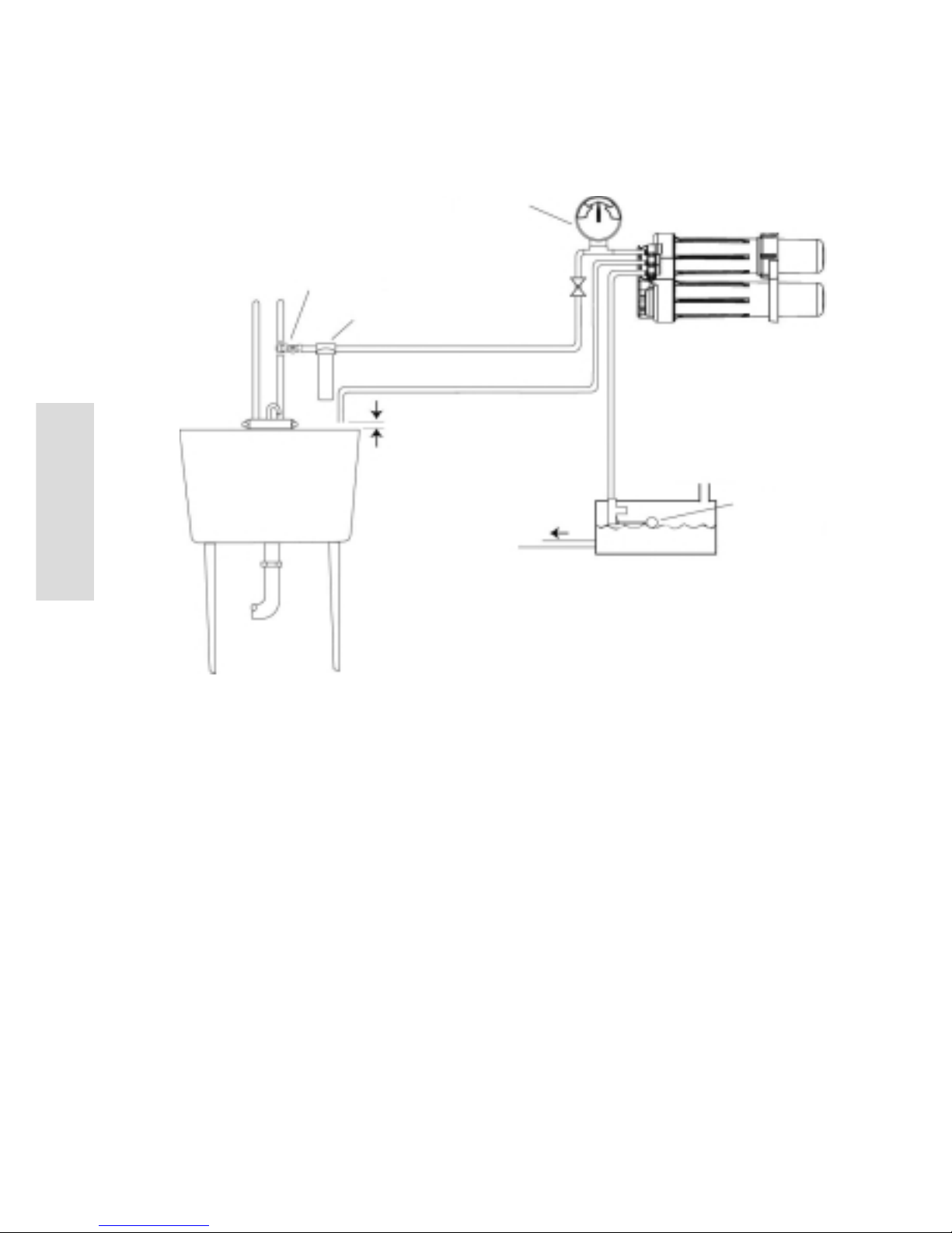
Figure 3 Typical Basement Installation
Floor
Feed Water Valve
Cold Water Line Only

E
N
G
L
I
S
H
9
2 - THE BASIC REVERSE OSMOSIS SYSTEM
Feed Pressure
Gauge
Feed Solenoid
Valve
Feed Water Valve
Cold Water Line Only
External Prefilter
Inlet-1/2” Natural
Drain - 3/8” Black
1.5” Air Gap Required
RO Assembly
To Point of Use
Product Storage Tank
Figure 4 Typical Light Commercial Installation
Vented to
Atmosphere
Liquid level float
sensor to control
feed solenoid valve
E
N
G
L
I
S
H
10
3 - INSTALLATION
STEP 1: Install cold water supply valve
STEP 2: Install drain adapter
STEP 3: Install faucet
STEP 4: Make tubing connections
STEP 5: Install RO assembly
STEP 6: Put system into operation
NOTE: Consult a licensed plumber if you are not familiar with plumbing procedures.
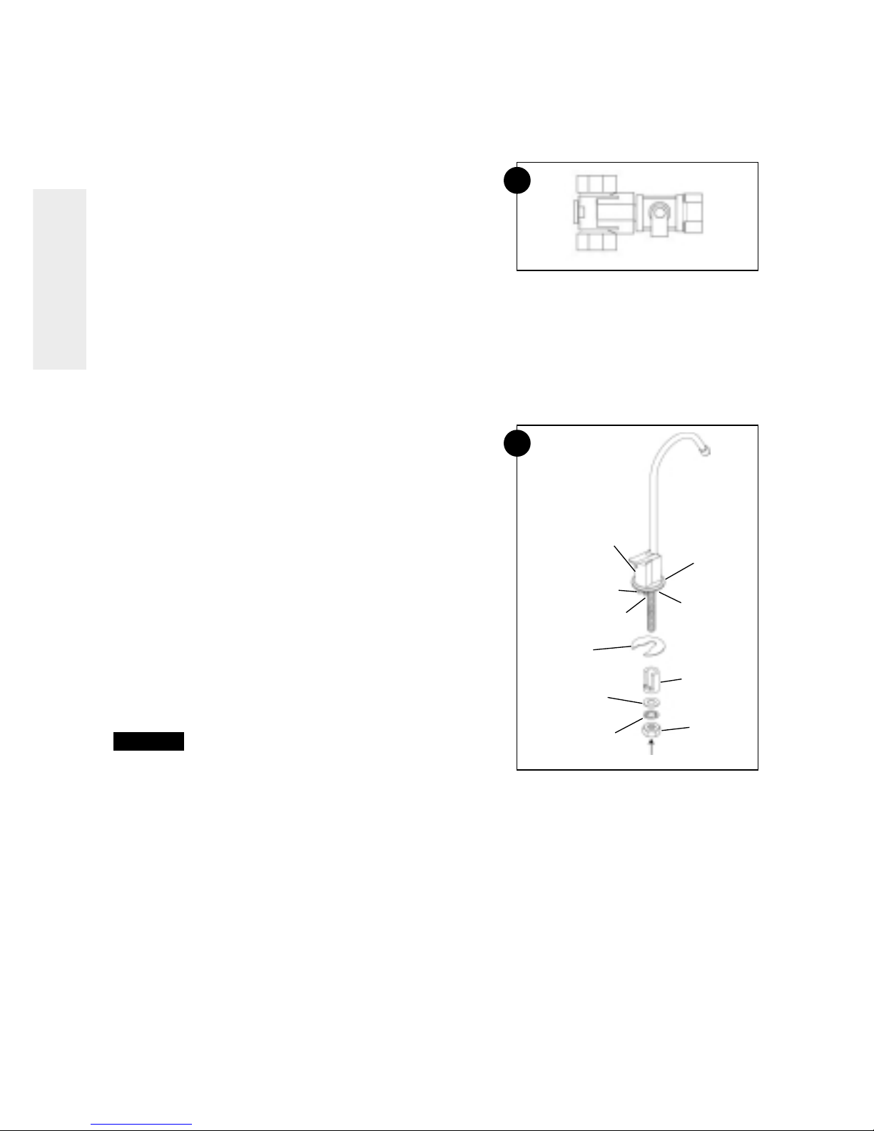
Step 1: Install cold water supply valve
Comply with local plumbing codes. A typical connection using a water supply valve is shown in Figure 5.
Water supply valve
NOTE: Be sure to turn off the water supply and open a low
faucet to drain the pipe.
Cold water pipes vary in size and style. The installer will
determine the type of valve that will be used. Install a valve on
the cold water supply pipe to adapt 1/2” OD tubing. If threaded
fittings are used, be sure to use pipe joint compound or Teflon
tape on outside threads. Turn the valve off.
Step 2: Install drain adapter
Follow the instructions in the Appendix for installation of the
Drain Boa™, if used.
The drain adapter is designed to fit 1”1/2 (3.8 cm) sink drain
pipe. The adapter installs directly to the sink tailpiece.
Step 3: Install faucet
A. Prepare mounting hole
1. Select a location for the faucet. Be sure it will fit flat against
the sink or counter and that there is space underneath for
tubing.
2. If drilling is needed, make a 1”1/2 diameter hole.
WARNING: To avoid damaging a sink, consult a qualified
plumber or installer for the proper method of drilling
holes in porcelain or stainless steel.
B. Assemble faucet
The tubing and fasteners are assembled to the faucet before the faucet is placed in position. This can be
done above the sink.
1. Slide the decorative ring over the tubing connections and up to the bottom of the faucet.
2. Slide the gasket over the tubing connections and up to the bottom of the faucet.
3. Slide the standoff onto the threaded tube, followed by the standard washer, the lock washer and nut.
4. Screw the threaded hose connector on the end of the threaded tube.
5
6
Air Gap Module
Horseshoe Clip
Washer
Locking Washer
Trim Ring
Gasket
Standoff
Nut
Water in Connection
1/2” Drain Connection
(Large Hose Barb)
3/8” Drain Connection
(Small Hose Barb)

11
E
N
G
L
I
S
H
3 - INSTALLATION
5. Connect the blue 3/8” product tubing by firmly pushing it into the connector.
6. Push the black 3/8” tubing onto the small hose barb. The red 1/2” tubing is pushed onto the large hose
barb.
7. Put the faucet into position.
8. The horseshoe clip is positioned around the threaded pipe
under the sink and above the standoff. This clip should
engage the tubing connected to the air gap.
9. Tighten the nut against the clip to hold the faucet in position.
Step 4: Make tubing connections
The connections to the faucet should be complete, the
remaining connections are:
• Feed connection-clear tubing from feed valve to white elbow
connector
• Drain connection-either red tubing from the air gap or black
tubing from grey elbow connector will attach to the drain
adapter
•Permeate connection-blue tubing from faucet to blue elbow
connection
• Attach the fittings to the manifold
A typical connection is shown in Figure 7: Side View and
Cutaway of Tubing Fitting.
NOTE: For optimal system performance, we recommend using
tubing lengths that are as short as possible.
Postfilter
Install the postfilter in line with the blue permeate tubing.
Make sure flow direction aligns with water path. Secure
tubing with collet lock clips.
Drain adapter (optional)
The drain adapter has a rubber inlet that accepts the 3/8”
black drain tube or the 1/2” red tube. The 3/8” black tubing will
connect here if the faucet is not using the air gap module.
When the tubing is in position, use the supplied hose clamps
to secure the connection.
NOTE: When sliding tubing into the drain adapter inlet, wet the
tubing. Water will help the tubing slide into the rubber
inlet.
Feed pressure gauge
The supplied pressure gauge can be connected to the feed
line to monitor system feed pressure. For proper system
performance, the dynamic feed pressure must be between
2.76 bar (40 psi) and 5.52 bar (80 psi) when the system is in
operation.
CAUTION: The feed pressure gauge is intended for use only during installation and troubleshooting of the RO
system. The pressure gauge should be removed during normal system operation because some
regulatory agencies did not evaluate the RO system with the feed pressure gauge in place.
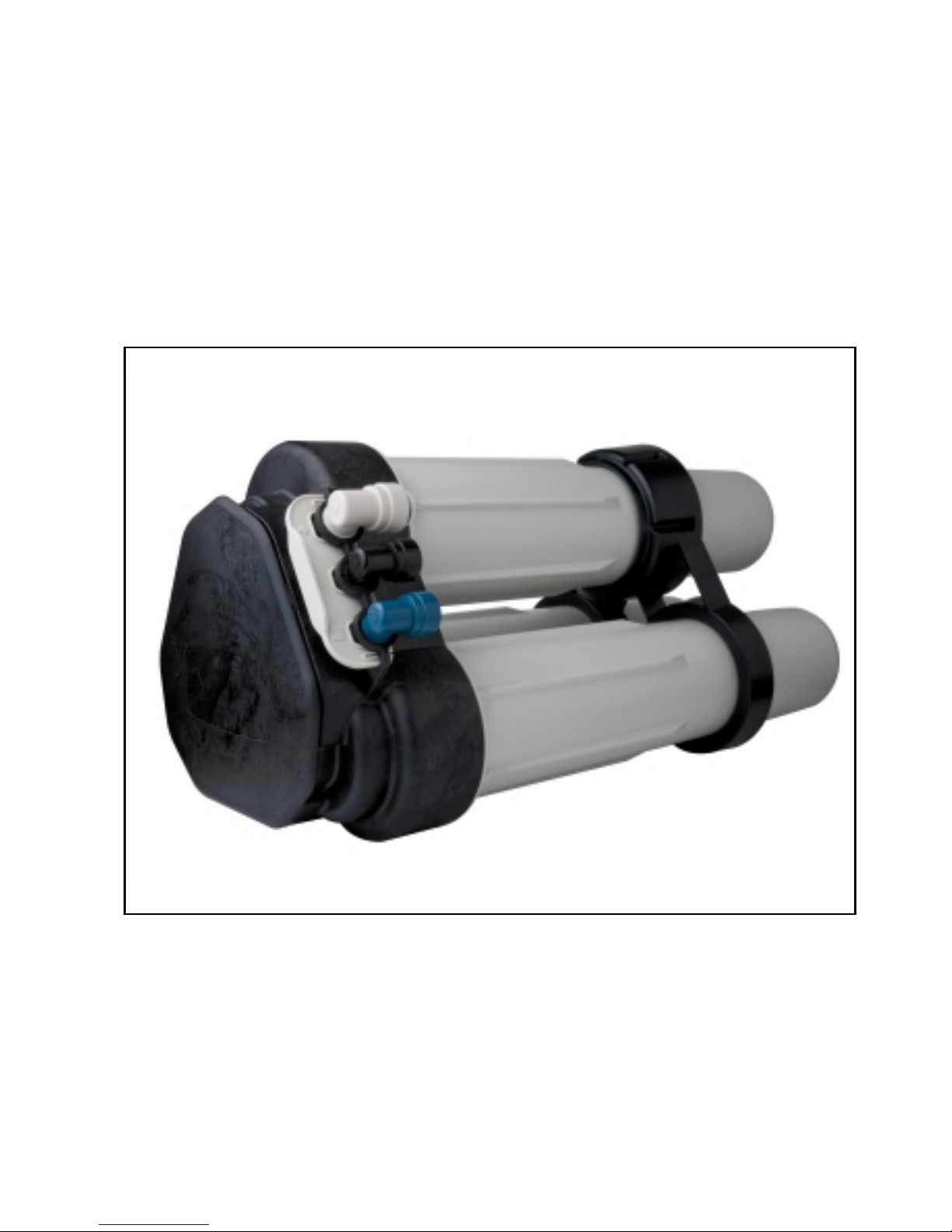
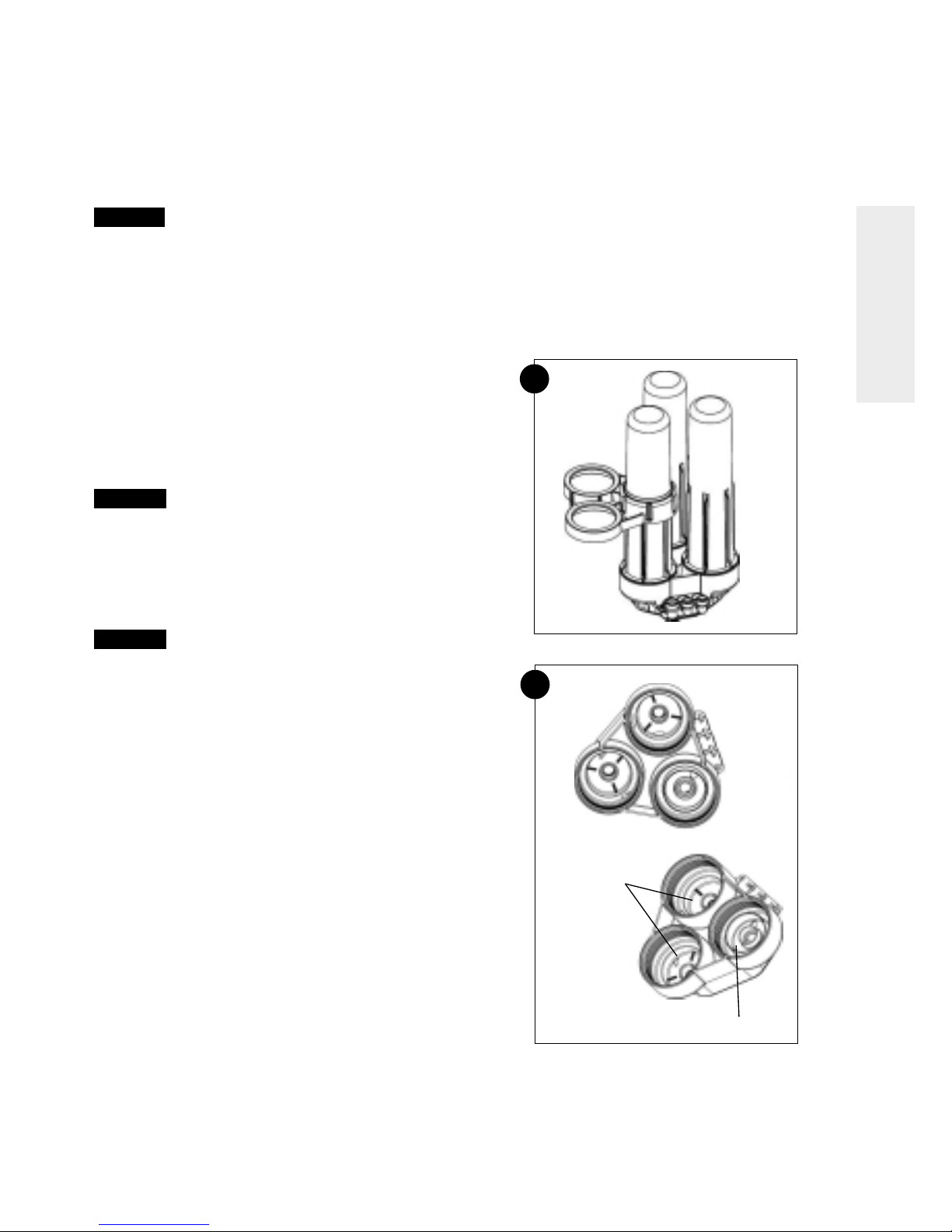
Step 5: Install RO assembly
The RO assembly includes the following components: sumps (3), support leg, prefilter, RO membrane
elements (2), and postfilter. The tubing is attached to the manifold by the elbow connectors. When choosing
a location for the system, allow enough tubing for it to be moved for periodic servicing of the filters and
membrane elements (Figure 8: RO assembly).
7
Collet
Lock Clip
Tubing
Collet
O-ring
8
Sumps
Support Leg
RO Assembly
Manifold
Prefilter
RO
Membranes
Elbow
Connectors
O-ring
Note: Make sure the tubing is pushed past the
O-rings for a secure fit. Also, when replacing
any tubing, cut tubing back 1/4“ prior to
re-inserting to prevent leaks.
Side View and Cutaway of Tubing Fitting

12
E
N
G
L
I
S
H
3 - INSTALLATION
WARNING:
Do not attempt to mount/hang the system. Do not
try to drill mounting holes anywhere on the
system.
If putting above ground/cabinet level, a sturdy,
permanent shelf is recommended.
Recommended placement positions
The RO assembly should be positioned in one of two ways.
The first position is with the unit standing upright using the
support leg with the sumps horizontal. The tubing is directed to
provide the best fit.
The second position, sets the unit on end so the sumps are
pointing up. The tubing is directed upward and the locking bar
is down to lock the tubing connections. See Figure 9: System
Positions.
NOTE: Ensure that the support leg is installed on the sumps.
Connection lubrication
Connections with O-rings must be properly lubricated. The
following instructions describe the method and locations for
lubrication.
Six packets of silicone lube are supplied. One packet should
be completely used to lubricate the O-ring contact surfaces in
the 3 manifold ports and 2 RO membrane locations (Figure 10).
Follow figure 11 and lubricate the filter seat and the flat
surface below the threads for the 3 sump locations. Use a
complete packet of silicone for each sump location.
NOTE: To properly lubricate the O-ring contact area, a film of
clean silicone grease is applied. The film should cover
all of the surface area that the O-ring will slide over and
seal with. Do not use grease containing petroleum
products.
9
System Positions
Locking Bar
Support Leg
First Position
Second Position
10
11
13
E
N
G
L
I
S
H
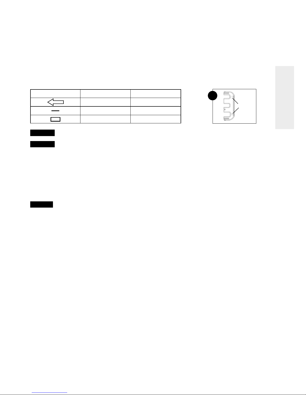
3 - INSTALLATION
The table below shows the coding system for the fitting connections. Each fitting has a unique “keyed”
socket on the manifold. Each fitting also has a graphic symbol molded into the elbow with a corresponding
symbol on the manifold.
WARNING:
Be sure to lubricate the manifold ports with silicone lubricant, prior to inserting the fittings into
manifold.
WARNING:
Do not turn the incoming water valve on until the locking bar is in place. When all of the
connections have been made, use the locking bar to hold the fittings in position. Match the
symbols on the locking bar to the corresponding symbols on the manifold (Figure 12).
Step 6: System startup
1. Inspect all connections.
2. Position manifold horizontal with openings facing up.
3. Remove new membrane elements from plastic packaging.
The black and yellow tapes surrounding the membrane are an important part of the membrane element
and should not be removed.
CAUTION:
Elements contain a foodgrade preservative. The use of sterile/latex gloves is recommended.
4. Lubricate all O-ring seats in the manifold that come in contact with the sump and element O-rings. Refer
to chapter "Connection Lubrication".
NOTE: To properly lubricate the O-ring contact area, a film of clean silicone grease is applied. The film
should cover all of the surface area that the O-ring will slide over and seal with. Do not use grease
containing petroleum products.
5. Securely insert O-ring end of membrane elements into manifold.
6. Remove prefilter from packaging. Check that gaskets are in place.
7. Place prefilter in manifold.
8. Replace sumps and tighten until it bottoms out.
Pressure test system
To check for leaks, the system must be filled with water and brought up to operating pressure.
1. Open cold water feed valve slowly. Run at 1/2 open for a minute, then open fully.
2. Open faucet until water runs.
3. Check for leaks.
NOTE: When the faucet is initially turned on, water may temporarily sputter from the air gap until the air is
purged. Allow 1 to 3 hours for any trapped air noise in the system to subside.
4. Purge the system. Open the faucet and run the water through the RO system for two to eight hours.
NOTE: A minimum of 2 hour flush is required to remove the food grade preservative. After 8 hours
performance will reach its stable maximum performance.
The RO system is now ready for use.
Connector symbol Connection Tubing color
Feed-Inlet Natural
Concentrate Black
Product Blue
Symbols
12

14
E
N
G
L
I
S
H
4 - TO CARE FOR THE RO SYSTEM
The components of the RO system are designed to function with minimal maintenance. However, the
membrane elements and filters will need to be replaced on a regular schedule.
For optimal performance the system should be flushed for 2 minutes if periods of inactivity extend past six
hours.
Replacement of prefilter and postfilter
The carbon/sediment prefilter reduces sediment and certain chemicals, such as chlorine, from the water.
Depending on water use and the amount of impurities, this filter should be replaced every six to twelve
months for point-of-use applications.
Whenever the prefilter is replaced, the postfilter should also be replaced.
Installations using more than 75,7 liter (20 gallons) product water per day should install external filters (not
supplied) to reduce chlorine and sediment larger than 10 microns.
Replacement of RO membrane elements
The functional life of the RO membrane elements will vary based on feed water quality. Product water
should be tested periodically to verify the membrane elements are performing properly. For most point-ofuse applications, the RO membrane elements should be replaced every two to four years.
NOTE: Softened water is recommended for optimal system performance and RO membrane element life.
15
E
N
G
L
I
S
H
5 - REPLACEMENT OF THE PREFILTER,
POSTFILTER, AND RO MEMBRANE ELEMENTS
1. Turn off the water supply to the RO System.
2. Reduce system water pressure by opening the faucet.
CAUTION:
Even with the water supply turned off the membrane and prefilter sumps will contain a
considerable amount of water. By positioning the RO assembly in a sink or tub, most of the water
will be contained.
3. Disconnect locking bar and place the fittings (with tubing still connected) into a tub or bucket.
4. Move system into a contained area, such as a sink or tub.
5. Remove the support leg from the three sumps and unscrew the top sump as shown to access the prefilter
element. The support leg functions as a wrench to loosen the sump, Figure 13.
NOTE:
• There is no need to disconnect tubing from fittings on the
manifold. Remove locking bar and pull fittings out. Lubricate
O-rings with silicone prior to re-assembly.
• If changing only the prefilter and postfilter, the other sumps
do not need to be removed.
• If changing the membrane elements, the prefilter and
postfilter should also be changed.
6. Remove exhausted prefilter and discard.
CAUTION:
The person handling the filters and membrane
elements must have clean hands to keep the
system sanitized. The use of sterile/latex gloves is
recommended.
7. If changing membrane elements:
a. Remove membrane sumps. Remove and discard used
elements.
b. Remove new elements from packaging.
CAUTION:
Elements contain a foodgrade preservative. The
use of sterile/latex gloves is highly recommended.
c. Lubricate element O-rings, brine seals, and sump O-rings
with silicone lubricant. Refer to chapter "Connection
Lubrication" for correct lubrication procedure of elements
cartridge.
d. Securely insert O-ring end of elements into manifold. See
Figure 13.
e. Replace sumps and tighten until it bottoms out.
NOTE: The system should be sanitized whenever a membrane
element or filter is replaced.
8. Sanitize the system.
a. The manifold should be positioned flat with the sump
connections facing up.
b. Pour a tablespoon (15 milliliters) of chlorine bleach into the
center opening of the prefilter sump connection. See Figure
14.
9. Install prefilter.
a. Remove new prefilter from packaging. Ensure gaskets are
secure. Insert prefilter into proper opening on manifold.
b. Lubricate sump O-ring with silicone lubricant.
c. With the prefilter element in place, screw the sump into the
connection. Tighten until it bottoms out.
13
14
Membrane Element
Locations
Prefilter Center Opening

16
E
N
G
L
I
S
H
5 - REPLACEMENT OF THE PREFILTER,
POSTFILTER, AND RO MEMBRANE ELEMENTS
10. Replace the postfilter.
a. To unlock the fittings from the tubing, push down on the collet sleeves and pull the tubing out.
b. Discard the exhausted postfilter.
c. To prevent leaks, cut the tubing back approximately 1/4” prior to connecting the new postfilter. Make sure
flow direction arrow aligns with water path. Reinsert tubing and collect locks.
11. Re-connect the fittings to the manifold and lock in position with locking bar.
12. Re-position the assembly and turn the water supply on. Check the system for any leaks.
CAUTION:
When the faucet is opened, water may sputter from the air gap until the trapped air is purged.
13. Open the faucet and run water for two minutes.
NOTE: Carbon fines may be present until the postfilter element is flushed out.
14. Shut off the faucet and allow the system to stand idle for 20 to 30 minutes.
15. Open the faucet and run water for five minutes.
16. Check for any system leaks.
NOTE: If the two RO membrane elements were replaced the system must be flushed according to Step 6
the system startup procedure as stated above.
The RO system is now ready for use.
17
E
N
G
L
I
S
H
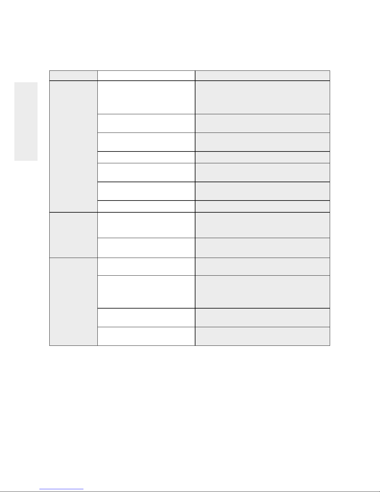
6 - SPECIFICATIONS
Performances
Minimum and maximum operating conditions
Condition Minimum Maximum
Inlet Pressure 2.76 bar (40 psi) 5.52 bar (80 psi )
Inlet Temperature 4.44°C (40°F) 37.78°C (100°F)
Inlet TDS 50 mg/L 2,000 mg/L
Inlet Hardness 0 mg/L (0 grain) 171 mg/L (10 grain)
Inlet Chlorine 0 mg/L 1.0 mg/L
Inlet Iron 0 mg/L 0.1 mg/L
Inlet Manganese 0 mg/L 0.05 mg/L
Inlet pH 4 10
Inlet Turbidity 0 1 NTU
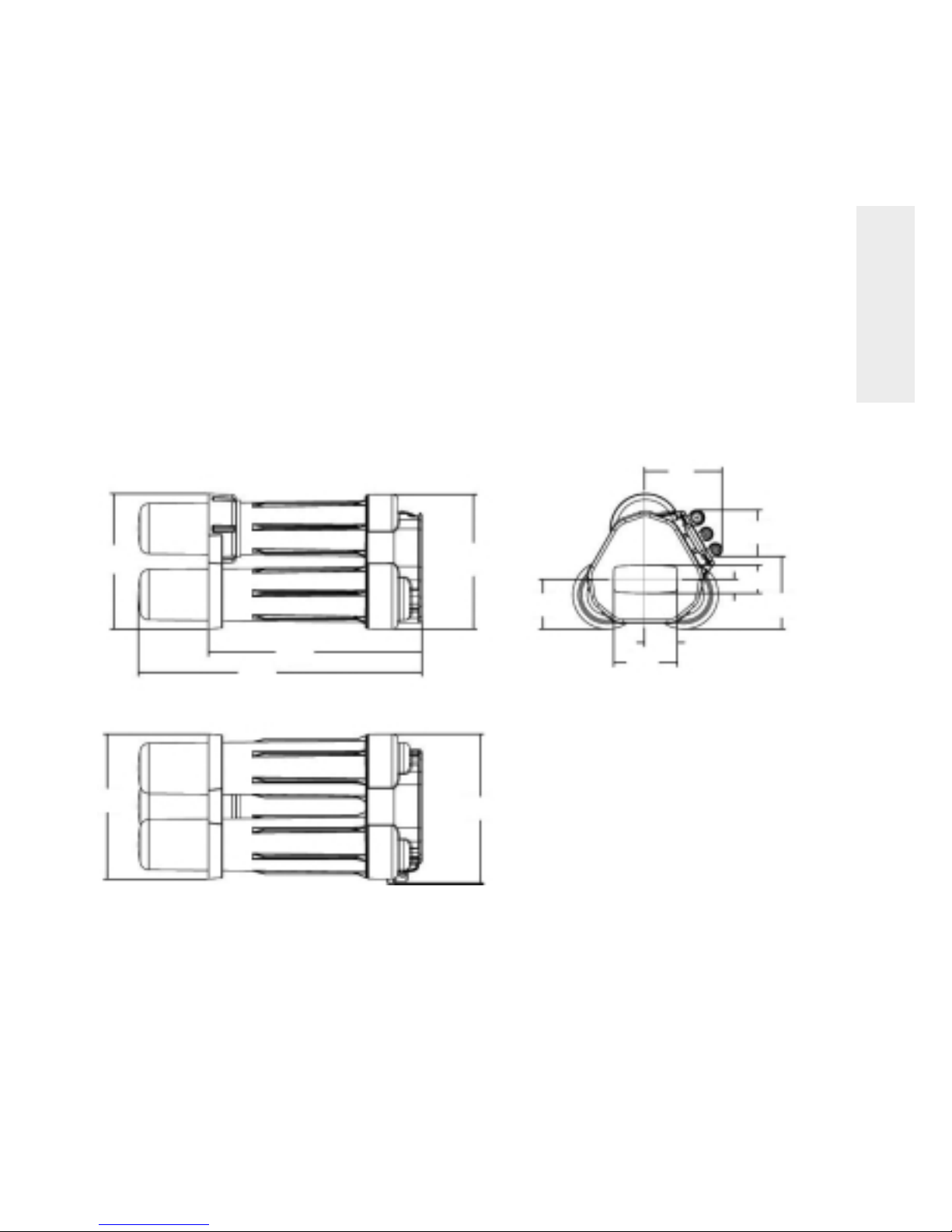
Dimensions
(243.9)
9.6
(508.9)
20.03
(383.5)
15.10
(242.5)
9.55
(89.8)
3.53
(140)
5.51
(84.3)
3.32
(130.4)
5.13
(59.4)
2.34
(114.3)
4.50
(25.4)
1.0
(50.8)
2.0
(261)
10.27
(268.2)
10.56
18
E
N
G
L
I
S
H
7 - TROUBLESHOOTING
Issue Possible Cause Corrective Action
Low product Increase feed pressure. Consider pump for low
flow rate Low driving pressure pressure locations. Use short tubing runs to decrease
flow restriction. Increase tubing diameter for longer
distances.
Low water temperature or high Increase feed water temperature or feed pressure to
total dissolved solids (TDS) compensate.
Plugged prefilter
Replace plugged prefilter. Consider sediment prefilter
for non-chlorinated applications.
Scaled or fouled RO membrane Replace membranes.
Faucets not adjusted properly Adjust faucet t-bar setting as tight as possible without
causing leaks from the faucet.
Plugged postfilter If flow into the postfilter is acceptable, replace
postfilter.
Leak or kink in product line Find and repair leak or kink.
Concentrate water
Replace plugged prefilter. Consider sediment prefilter
runs to drain after Plugged prefilter
for non-chlorinated applications.
faucet shut off
Leak in product line
Find and repair leak. Install pressure gauge in product
line to help identify a product pressure leak.
Poor product Water sample taken during Take sample after three minutes of continuous
water quality system flush operation.
Increase feed pressure. Consider pump for low
Low driving pressure
pressure locations. Use short tubing runs to decrease
flow restriction. Increase tubing diameter for longer
distances.
Plugged prefilter
Replace plugged prefilter. Consider sediment prefilter
for non-chlorinated applications.
Scaled, fouled, or damaged
RO membrane
Replace RO membranes.

19
F
R
A
N
Ç
A
I
S
TABLE DES MATIÈRES
1 MESURES DE SÉCURITÉ P. 20
2 SYSTÈME D’OSMOSE INVERSE BASIQUE P. 21
3 INSTALLATION P. 27
4 ENTRETIEN DU SYSTÈME OI P. 31
5 REMPLACEMENT DU PRÉFILTRE,
DU FILTRE DE SORTIE ET DES MEMBRANES OI P. 32
6 SPÉCIFICATIONS P. 34
7 GUIDE DE DÉPANNAGE P. 35
8 INFORMATION ET INSTRUCTIONS D’INSTALLATION
POUR RACCORD À L’ÉGOUT, DRAIN-BOA
TM
MODÈLE DC 9700 P. 87

20
1 - MESURES DE SECURITE
Lisez et effectuez attentivement toutes les étapes et les mises en garde avant d’installer et d’utiliser votre
système d’osmose inverse.
N’utilisez pas ce produit pour obtenir de l’eau traitée à partir de sources d’eau non potable. Cet appareil
n’est pas prévu pour traiter de l’eau microbiologiquement dangereuse ou de qualité inconnue sans prévoir,
avant ou après, une désinfection adéquate.
Ce système d’osmose inverse contient des consommables (membranes). Ces composants sont essentiels
pour une réduction efficace dans l’eau des sels dissouts et de certains contaminants listés sur le feuillet
technique du système.
Le système d’osmose inverse n’inclut pas de dispositif de surveillance des contaminants. Afin d’être certain
que le système fonctionne correctement, l’eau purifiée par ce système devrait être testée régulièrement
(tous les 6 mois) par l’installateur ou un laboratoire certifié.
Consultez l’administration compétente pour obtenir les codes de plomberie à l’installation du système.
Suivez les codes locaux s’ils diffèrent de ceux de ce manuel.
Cet appareil d’osmose inverse fonctionne à une pression d’eau comprise entre 2.8 bars (40 psi) minimum et
5.5 bars (80 psi) maximum. La pression de l’eau peut être réduite en installant une vanne de réduction de
pression dans le conduit d’arrivée d’eau relié à l’appareil d’osmose inverse. Un surpresseur doit être utilisé
si la pression est faible.
Ne soumettez pas cet appareil à des températures extrêmes, froides ou chaudes. La température de
l’arrivée d’eau à l’appareil doit être comprise entre 4°C (40°F) et 38°C (100°F). N’installez pas le système sur
une canalisation d’eau chaude.
Les membranes d’osmose inverse contiennent un conservateur alimentaire pour le stockage et le
transport. Chaque membrane neuve doit être rincée pendant 2 heures au moins afin d’éliminer toute trace
du conservateur. Le conservateur n’est pas nocif mais donne un goût désagréable à l’eau.
Ce rinçage agit aussi sur la performance de la membrane : chaque membrane neuve atteindra sa
performance maximale après 8 heures de rinçage.
F
R
A
N
Ç
A
I
S

21
F
R
A
N
Ç
A
I
S
2 - SYSTEME D’OSMOSE INVERSE BASIQUE
Votre système d’osmose inverse (OI) est un appareil de traitement de l’eau. Il utilise la pression de l’eau pour
inverser un processus physique naturel appelé osmose. L’eau, sous pression, passe à travers une membrane
semi-perméable pour filtrer les minéraux et les impuretés. L’eau potable propre arrive au robinet tandis que les
minéraux et les impuretés sont envoyés à l’égout avec les eaux usées de l’OI.
Le système comporte des filtres et des membranes remplaçables. Le préfiltre élimine le sable, le limon, les
saletés, les particules de rouille, les autres sédiments et le chlore présents dans l’eau avant sont passage dans
les membranes d’OI. Le filtre de sortie élimine tous les goûts et/ou les odeurs qui persistent parfois dans l’eau
après son passage à travers les membranes OI.
Avant d’installer le système OI
• Le système fonctionnera au mieux de sa performance lorsque l’eau à l’entrée aura été traitée (adoucie).
• L’eau d’entrée du système doit présenter certaines limites en termes de sédiments, pression, etc. Reportez-vous
aux caractéristiques techniques pour savoir si votre installation se trouve bien dans ces limites.
• Une analyse de la qualité de l’eau peut être réalisée pour évaluer si l’eau d’entrée doit être traitée. Contactez
votre distributeur/installateur.
• Les filtres et membranes du système OI doivent être remplacés régulièrement. Suivez les instructions de
remplacement incluses dans le présent manuel.
REMARQUE : Pour un fonctionnement optimal du système, faites fonctionner l’appareil au moins 2 minutes en
continu chaque jour.
AVERTISSEMENT : Le système OI est conçu pour fonctionner sans réservoir de stockage. NE PAS brancher un
réservoir de stockage pressurisé au tuyau de perméat. L’utilisation d’un réservoir pressurisé
affectera négativement les performances du système.
Outils et matériel nécessaires
• Clé anglaise et pinces à tête réglable plus grosses ou une clé à pipe pour le rejet
de l’évier
• Scie pour couper le tuyau de rejet
• Tournevis cruciforme et tournevis pour écrous à fente
• Coupe-tube
• Perceuse électrique et mèches pour couper l’orifice de montage du robinet
REMARQUE : Certains éviers disposent d’un trou déjà percé avec une bonde pour
le robinet.
22
2 - SYSTEME D’OSMOSE INVERSE BASIQUE
F
R
A
N
Ç
A
I
S
Certaines configurations n’incluent
pas nécessairement tous
les composants listés ci-dessous
Kit d'installation raccords
et barre de verrouillage
PN 4000330
Barre
de verrouillage
PN 3038026
(1 pc)
Coude de séparation
de l'alimentation
blanc
PN 3035307
(1 pc)
Coude de séparation
du produit filtré
bleu
PN 3035305
(1 pc)
Raccord
de robinet
PN 3038251
(1 pc)
Tube de lubrifiant
silicone usage unique
PN 1013501
(6 pcs)
Attache
de blocage
de collier 3/8"
PN 3038239
(5 pcs)
Attache
de blocage
de collier 1/2"
PN 3038250
(2 pcs)
Coude
de séparation
de l'évacuation
noir
PN 3035306
(1 pc)
Carter
PN 1239705
(3 pcs)
Joint torique
PN 1240326
(3 pcs)
Tuyau 3/8" noir
(4 ft)
Tuyau 3/8" bleu
(4 ft)
Tuyau 1/2"
transparent (4 ft)
Tuyau 1/2" rouge
(3 ft)
Manifold -
complet
PN 4000445
(1 pc)
Kit de la
tuyauterie
d'installation
PN 1255736
Manomètre
PN 3002494
(1 pc)
Membrane
(TFC-350 IND)
PN 4000569
(2 pcs)
Carter
et joint
torique
Jambe
de support
PN 3038021
(1 pc)
Composants supplémentaires
(voir tableau ci-dessous)
Préfiltre
au charbon
PN 303833
(1 pc)
Note: pour les
applications où
l'eau est chlorée
Note: pour les
applications où l'eau
n'est pas chlorée
Figure 1
Préfiltre
sédiment
PN 1266690
(1 pc)
Postfiltre
charbon
PN 255526-09
(1 pc)
Kit d'évacuation
Boa
PN 1240564
(1 pc)
Robinet avec disrupteur
de charge
PN 3020487
(1 pc)

23
F
R
A
N
Ç
A
I
S
2 - SYSTEME D’OSMOSE INVERSE BASIQUE
Emplacement du système
Le système d’osmose inverse est conçu pour être installé sous un évier, généralement dans la cuisine ou la salle
de bain. Il peut être posé sur le sol dans une position qui n’induit pas de pression sur les coudes de déconnexion.
Le robinet d’eau traitée OI s’installe sur l’évier ou sur le plan de travail à côté de l’évier.
L’appareil peut également être placé à distance du robinet. Pour cela, une source d’alimentation en eau et un rejet
à l’égout sont nécessaires.
REMARQUE :
• N’utilisez pas de tuyaux trop longs car cela affaiblirait les performances du système. Un surpresseur peut être
utilisé sur la conduite d’arrivée d’eau.
• Toute la tuyauterie doit être réalisée conformément aux règlementations nationales et locales. Certaines
législations requièrent parfois l’installation par un plombier agréé; vérifiez avec les autorités locales avant de
procéder à l’installation.
AVERTISSEMENT : Tous les composants et les tuyaux doivent être placés dans une zone qui n’est pas exposée
au gel. Ne pas exposer l’appareil ou les tuyaux à la lumière du soleil.
Alimentation en eau : Pour amener l’eau à l’entrée du système OI, un raccord sur la conduite d’arrivée d’eau
principale est nécessaire ou l’installation de raccords de canalisation peut être nécessaire. La vanne d’arrivée
d’eau doit être aussi proche que possible du manifold. UTILISEZ UNIQUEMENT UNE ARRIVEE D’EAU POTABLE.
L’eau adoucie est préférable car elle prolonge la vie de la membrane OI.
Rejet à l’égout : Un rejet à l’égout approprié est nécessaire pour l’évacuation de l’eau rejetée par le système OI.
Un siphon de sol, un bac à laver, un tuyau de chute, un puisard, etc. sont tous acceptables. Si le rejet se fait dans
un évier de buanderie ou par la colonne de service, un espace d’air supérieur à 3,8 cm (1/2”) doit être prévu audessus de la surface d’évacuation. Un adaptateur de siphon en P pour évier est prévu pour être installé comme
rejet à l’égout optionnel lorsque la réglementation le permet.
Ne pas relier le tuyau d’évacuation du système au tuyau de rejet du lave-vaisselle ou près du traitement des
ordures. La pression de retour de ces appareils risque de provoquer le refoulement du disrupteur de charge.
Robinet de distribution : Le robinet doit être placé près de l’évier, là où l’eau de boisson est habituellement
distribuée. La commodité d’utilisation (remplissage de pichets et de verres d’eau) et une zone dégagée au dessous
du robinet sous l’évier pour fixer le tuyau d’eau traitée et le rejet à l’égout sont des considérations à prendre en
compte. Une surface plate d’un diamètre de 5 cm (2”) est nécessaire au-dessus et au-dessous du lieu
d’installation. L’épaisseur de la surface de montage ne doit pas dépasser 3,2 cm (1”1/4). Evitez toute sangle de
maintien sous le dessous de l’évier.
Manifold : Le manifold peut être installé à droite ou à gauche sous l’évier ou dans le meuble. L’installation au soussol est également possible, par exemple, près de l’évier de la buanderie, là où l’arrivée d’eau froide potable et
l’accès à l’égout sont proches. L’emplacement choisi doit laisser suffisamment d’espace pour permettre le
remplacement des membranes.
Lorsque l’espace sous l’évier est restreint, il sera plus facile d’installer en premier le robinet. Laissez une longueur
de tuyau appropriée pour l’installation finale du système.

F
R
A
N
Ç
A
I
S
2 - SYSTEME D’OSMOSE INVERSE BASIQUE
24
Robinet avec disrupteur
de charge
Rejet 1/2" rouge
Perméat 3/8" bleu
Postfiltre charbon
Manomètre
Barre de verrouillage
Préfiltre
Membrane
d'osmose
inverse
Jambe
de support
(outil pour
dévisser
les carters)
Raccord à l'égout
Installer au-dessus du siphon en P
Raccords
coudés
Manifold
Concentrat 3/8" noir
Arrivée d'eau 1/2"
transparent
Vanne d'arrivée d'eau
Ligne d'eau froide
uniquement
Maintenir une
distance minimale
Figure 2 : Installation standard sous l'évier

F
R
A
N
Ç
A
I
S
25
2 - SYSTEME D’OSMOSE INVERSE BASIQUE
Robinet sans
disrupteur de charge
Perméat 3/8" bleu
Maintenir une distance minimale
Postfiltre charbon
Arrivée d'eau 1/2" transparent
Concentrat 3/8" noir
Système d'osmose inverse
Espace d'air requis: 1,5"
Figure 3 : Installation standard dans une cave
Sol
Vanne d'arrivée d'eau
ligne d’eau froide uniquement
26
F
R
A
N
Ç
A
I
S
2 - SYSTEME D’OSMOSE INVERSE BASIQUE
Manomètre
Vanne solénoïde
en entrée
Vanne d'arrivée d'eau
Ligne d'eau froide uniquement
Préfiltre externe
Arrivée d'eau 1/2" transparent
Concentrat 3/8" noir
Espace d'air requis: 1.5"
Système d'osmose inverse
Au point d'utilisation
Réservoir de stockage de perméat
Figure 4 : Installation semi-commerciale standard
En contact avec
l'atmosphère
Contacteur de niveau
relié à la vanne
solénoïde en entrée
 Loading...