


FILTRATION & PROCESS
5730 NORTH GLEN PARK ROAD, MILWAUKEE, WI 53209
P: 262.238.4400 | 800.279.9404
www.pentairaqua.com
PRF26K, PRF34K, and PRF40K
Water Softening System
INSTALLATION INSTRUCTIONS
English .............................. Pages 2-19
Repair Parts. . . . . . . . . . . . . . . . . . . . . . . . . . . . .Page 14
Manual de Sistema ablandador
de agua
INSTRUCCIONES DE INSTALACIÓN
Español .......................... Páginas 20-37
Piezas de repuesto ..................... Página 32
Manuel
Adoucisseur d'eau
INSTRUCTIONS D’INSTALLATION
Français ............................ Pages 38-55
Piéces de Rechange ..................... Page 50
Tools and Fittings Required
• Pipe Cutter
• Tubing Cutter
• File
• Pliers
• Tape Measure
• Soldering Tools
• Lead Free Solder
• Bucket
• Towel
• PTFE Pipe Tape
• Adjustable Wrench
• Tube 100% Silicone Grease
Tested and Certied by WQA to NSF/
ANSI Standard 44 & 372 for softener
performance & lead free compliance and
CSA B483.1.
Herramientas y accesorios
necesarios
• Sierra para cortar tuberías
• Cortatubos
• Lima
• Pinzas
• Cinta métrica
• Herramientas para soldar
• Soldador libre de plomo
• Cubeta
• Toalla
• Cinta de PTFE para tubería
• Llave ajustable
• Tubo de grasa 100% de silicona
Probado y certicado por la WQA
según la norma 44 y 372 de NSF/ANSI
por el desempeño del suavizador y el
cumplimiento del no contenido de plomo
y CSA B483.1.
Outils et accessoires requis
• Coupe-tuyau
• Coupe-tube
• Lime
• Pince
• Mètre ruban
• Outillage de brasage
• Brasure sans plomb
• Seau
• Serviette
• Ruban pour tuyau en PTFE
• Clé ajustable
• Graisse de silicone à 100 %
pour tube
Testé et certié par WQA conforme
à la norme 44 et à la norme 372 de
NSF/ANSI pour la perfomance des
adoucisseurs et pour la conformité à
l'exemption de plomb et CSA B483.1.
For further operating, installation, maintenance,
parts or assistance:
Call Technical Service at:
800.297.9404
Para obtener más información sobre el
funcionamiento, la instalación, el mantenimiento,
las piezas o para obtener asistencia:
Comuníquese con el Servicio de atención
al cliente al: 800.297.9404
Pour de tout autre renseignement concernant
le fonctionnement, l’installation ou l’entretien:
Appelez le service à la clientèle en composant le : 800.297.9404
WARNING:
1
TABLE OF CONTENTS
Contents
MANUAL OVERVIEW ............................................................2
PARTS INCLUDED ................................................................2
EQUIPMENT INSTALLATION ................................................2
CONTROL OPERATION & LAYOUT ......................................9
PROGRAMMING ....................................................................10
AUTOMATIC RECHARGE .....................................................11
MANUAL REGENERATION ...................................................11
QUICK CYCLING THE CONTROL .........................................11
CYCLE DEFAULTS TABLE ....................................................11
START-UP ..............................................................................12
INSTALLATION CHECKLIST .................................................12
CARE AND USE OF YOUR BRINE TANK .............................13
SYSTEM DISINFECTION ......................................................13
ACCESSING HISTORY VALUES ...........................................13
TANK ASSEMBLY ..................................................................14
VALVE ASSEMBLY .................................................................15
BRINE WELL ASSEMBLY CH15675 ......................................16
TROUBLESHOOTING ...........................................................17
PERFORMANCE DATA SHEET .............................................19
MANUAL OVERVIEW
2
3
4
9
Manual
10
How To Use This Manual
This installation manual is designed to guide the installer
through the process of installing and starting the system.
This manual is a reference and will not include every system
installation situation. The person installing this equipment
should have:
• Knowledge in the water softener installation
• Basic plumbing skills
Icons That Appear In This Manual
Failure to follow this instruction can result in
personal injury or damage to the equipment.
NOTE: This will make the process easier if followed.
Inspection
Inspect the unit for damage or missing parts. Contact your
supplier if any discrepancies exist.
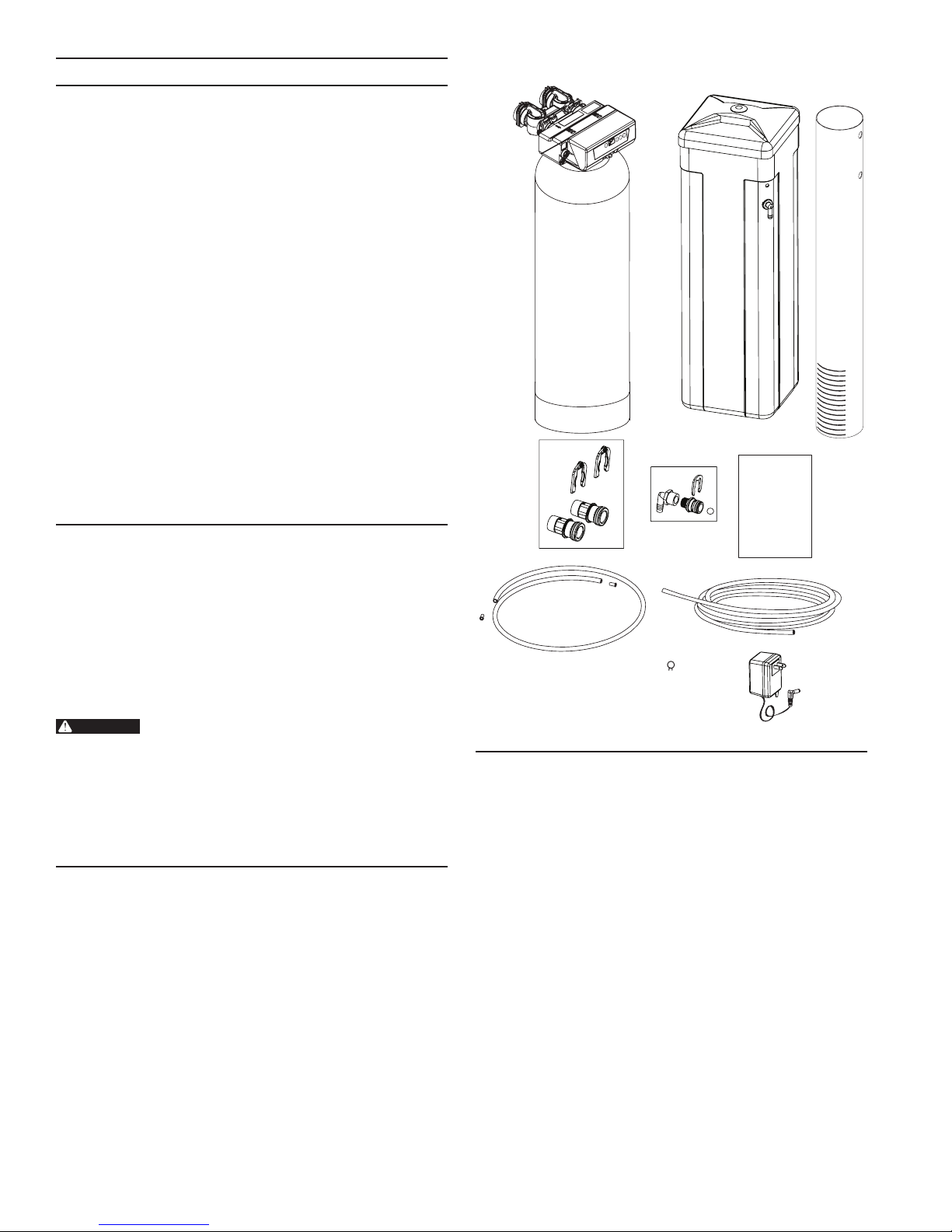
PARTS INCLUDED
The PRF Water Softening System should have the following
parts:
1. Softener Tank with Valve and Bypass
2. Salt Tank with Cover
3. Connector Kit
4. Drain Line Flow Control and Drain Fitting
5. Brine Line Tubing with End Inserts
(shipped inside the Brine Well #10)
6. Drain Line Tubing
7. Tubing Clamp
8. Wall Transformer
9. Instruction Manual
10. Brine Well
5
7
6
8
EQUIPMENT INSTALLATION
General Warnings And Safety Information
Electrical
There are no user-serviceable parts in the AC adapter, motor,
or controller. In the event of a failure, these should be replaced.
• All electrical connections must be completed according to
local codes.
• Use only the power AC adapter that is supplied. If the AC
adapter is replaced use a Class II, 12 volt, 150 mA supply.
• The power outlet must be grounded and always on.
• To disconnect power, unplug the AC adapter from its
power source.
• Install an appropriate grounding strap across the inlet
and outlet piping of the water system to ensure proper
grounding is maintained.
2 • PRF26K, PRF34K, and PRF40K

Mechanical
• Do not use petroleum based lubricants such as vaseline,
oils, or hydrocarbon based lubricants. Use only 100%
silicone lubricants.
• All plastic connections should be hand tightened.
Plumber's tape should be used on connections that do not
use an O-ring seal. Do not use pliers or pipe wrenches.
• All plumbing must be completed according to local codes.
• Soldering of the plumbing should be done before
connecting to the valve. Excessive heat will cause interior
damage to the valve.
• Observe drain line requirements.
• Do not use lead-based solder for sweat solder
connections.
• The drain line must be a minimum of 1/2-inch diameter.
Use 3/4-inch pipe if the pipe length is greater than
20 feet (6 m).
• Do not support the weight of the system on the control
valve ttings, plumbing, or the bypass.
• It is not recommended to use sealants on the threads.
Use Plumber's tape on all NPT threads.
General
• Observe all warnings that appear in this manual.
• This system is not intended to be used for treating water
that is microbiologically unsafe or of unknown quality
without adequate disinfection before or after the system.
• Keep the unit in the upright position. Do not turn on side,
upside down, or drop. Turning the tank upside down will
cause media to enter the valve.
• Operating ambient temperature is between 34°F (1°C)
and 120°F (49°C).
• Operating water temperature is between 35°F (1°F) and
100°F (38°C).
• Working water pressure range is 20 to 125 psi
(1.38 to 8.61 bar). In Canada the acceptable working
water pressure range is 20 to 100 psi (1.38 to 6.89 bar).
• Use only salts designed for water softening. Acceptable
salt type is sodium chloride pellet salt.
• Follow state and local codes for water testing. Do not
use water that is micro biologically unsafe or of unknown
quality.
• When lling media tank, do not open water valve
completely. Fill tank slowly to prevent media from exiting
the tank.
• Always make modications to house plumbing rst.
Connect to valve last.
• Plastic parts and O-rings may be damaged by heat and
solvents. When constructing plumbing connections allow
heated parts to cool and protect parts from solvents.
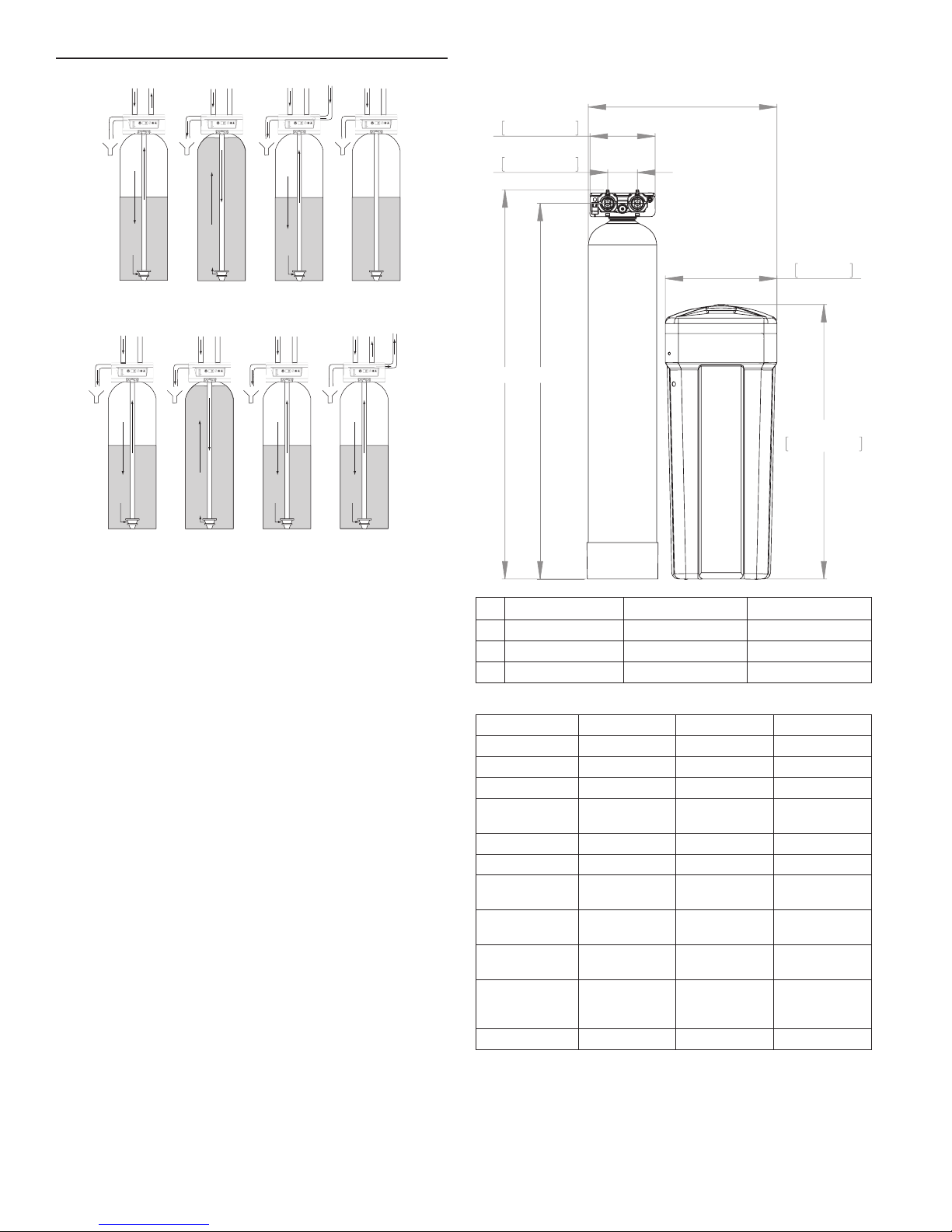
System Recharge Cycles
Service (Downow):
Untreated water is directed down through the resin bed and up
through the riser tube. The hardness ions attach themselves
to the resin and are removed from the water. The water is
conditioned as it passes through the resin bed.
When a recharge cycle starts, the softener goes through
seven cycles. During the recharge cycle the softener will allow
untreated water to bypass into the building.
1. Backwash 1 (Upow):
The ow of water is reversed by the control valve and
directed down the riser tube and up through the resin bed.
During the backwash cycle, the bed is expanded and debris
is ushed to the drain.
2. Brine Draw (Downow):
The brine draw cycle takes place during the slow rinse
cycle. The control directs water through the brine injector
and brine is drawn from the salt tank. Brine draw is
completed when the air check in the salt tank closes.
Slow Rinse (Downow):
The brine is directed down through the resin bed and up
through the riser tube to the drain. The hardness ions are
displaced by sodium ions and are sent to the drain. The
resin is recharged during the brine cycle.
3. Repressurize Cycle (Hard Water Bypass Flapper Open):
This cycle closes the appers for a short time to allow the
air and water to hydraulically balance in the valve before
continuing the recharge.
4. Fast Rinse 1 (Downow):
The control directs water down through the resin bed and
up through the riser tube to the drain. Any remaining brine
residual is rinsed from the resin bed.
5. Backwash 2 (Upow):
The ow of water is reversed by the control valve and
directed down the riser tube and up through the resin bed.
During the backwash cycle, the bed is expanded and debris
is ushed to the drain.
6. Fast Rinse 2 (Downow):
The control directs water down through the resin bed and
up through the riser tube to the drain. Any remaining brine
residual is rinsed from the resin bed.
7. Brine Rell:
Water is directed to the salt tank at a controlled rate, to
create brine for the next recharge.
PRF26K, PRF34K, and PRF40K • 3
EQUIPMENT INSTALLATION continued
From Regenerant
Tank
SERVICE
BACKWASH
Cycle 1
BRINE/SLOW RINSE
Cycle 2
REPRESSURIZE
Cycle 3
To Regenerant
Tank
8.75in
222.25mm
4.00in
101.60mm
A
B
C
15.00in
381mm
36.91in
937.55mm
FAST RINSE
Cycle 4
BACKWASH
Cycle 5
FAST RINSE
Cycle 6
BRINE REFILL
Cycle 7
Figure 1 Flow Patterns
Location Selection
Location of a water treatment system is important. The
following conditions are required:
• Level platform or oor.
• Ambient temperatures over 34°F (1°C) and below 120°F
(49°C).
• Water pressure below 125 psi (8.61 bar) and above
20 psi (1.4 bar).
• In Canada the water pressure must be below 100 psi
(6.89 bar).
• Constant electrical supply to operate the controller.
• Total minimum pipe run to water heater of ten feet (three
meters) to prevent backup of hot water into system.
• Local drain or tub for discharge as close as possible.
• Water line connections with shutoff or bypass valves.
• Must meet any local and state codes for site of
installation.
• Valve is designed for minor plumbing misalignments. Do
not support weight of system on the plumbing.
• Be sure all soldered pipes are fully cooled before
attaching plastic valve to the plumbing.
• Room to access equipment for maintenance and adding
salt to tank.
PRF26K PRF34K PRF40K
A 48.3 in (1266.8 mm) 52.33 in (1329.2 mm) 48.4 in (1229.4 mm)
B 46.5 in (1181.1 mm) 50.51 in (1282.9 mm) 46.6 in (1183.6 mm)
C 24.36 in (618.7 mm) 25.36 in (644.23 mm) 26.36 in (669.54 mm)
System Specications
Model PRF26K PRF34K PRF40K
Recharge Style Meter - Demand Meter - Demand Meter - Demand
Media Tank Size 8" x 44" 9" x 48" 10" x 44"
Resin Volume 0.80 Ft
Recharge (Salt)
Tank Size
Salt Storage 240 lbs 240 lbs 240 lbs
Drain Water Rate 2.1 GPM 2.1 GPM 2.7 GPM
Service
Connection Size
Drain Connection
Size
Recharge (Brine)
Connection Size
Installation
Space
Requirements
Shipping Weight 78 lbs 95 lbs 110 lbs
25" W x 15" D 25" W x 15" D 26" W x 15" D
3
14" x 34" 14" x 34" 14" x 34"
1" NPT 1" NPT 1" NPT
1/2" NPT 1/2" NPT 1/2" NPT
3/8" NPT 3/8" NPT 3/8" NPT
1.04 Ft
3
1.25 Ft
3
4 • PRF26K, PRF34K, and PRF40K

WARNING:
EQUIPMENT INSTALLATION continued
CAUTION!
REMOVE BRINE T
WARNING:
WARNING:
Outdoor Locations
It is recommended that the system be installed indoors. When
the water conditioning system must be installed outdoors,
several items must be considered.
• Moisture — The valve and controller are rated for NEMA
3 locations. Falling water should not affect performance.
The system is not designed to withstand extreme humidity
or water spray from below. Examples are: constant heavy
mist, near corrosive environment, upwards spray from
sprinkler.
• Direct Sunlight — The materials used will fade or discolor
over time in direct sunlight. The integrity of the materials
will not degrade to cause system failures.
• Temperature — Extreme hot or cold temperatures may
cause damage to the valve or controller.
Freezing temperatures will freeze the water in the valve.
This will cause physical damage to the internal parts as
well as the plumbing.
• Insects — The controller and valve have been designed
to keep all but the smallest insects out of the critical
areas.
Things You Need to Know
• When the controller is rst plugged in, it may display
an Err 3, this means that the controller is rotating the
camshaft to the home position.
• The preset default time of recharge is 2:00 AM.
• The controller is programmed to recharge if a recharge
has not taken place in the last 7 days. This setting cannot
be changed.
• Make sure control power source is plugged in. The
transformer should be connected to a non-switched
power source.
• Unless changed, the settings for a newly installed system
are:
Hardness - 25 grains per gallon
Salt Setting - HC (High Capacity)
Internal System clock starts at 0 hours (midnight)
The rst recharge will occur when the system clock
reaches 2:00 AM
• Test your water. Take a 4-5 oz sample of your water to
someone who can test for hardness. This information will
be used to setup the control.
Inspection
The system is shipped with several parts unassembled. When
parts are removed from the packing, they should be inspected
for damage. If any parts are damaged or missing, contact your
supplier.
When handling the media tank do not turn it
upside down or drop on its side.
When the carton is rst opened, the softener will be standing
upright.
ANK SLOWLY
3
5
1
2
Figure 2
The brine tank ts tightly over the valve.
When removing the brine tank tip it forward
and rotate slightly to pull off. Take care not
to damage valve cover or control.
To assemble the system, remove the salt tank components
(cover, tank and brine tube assembly) from the shipping
container.
1. Remove the brine well, parts box and brine line.
2. Lift the brine tank off unit
3. Tilt the brine tank forward and slowly lift free.
The media tank can now be removed.
To Assemble the Salt Tank:
1. Stand the salt tank up and in position. Level as needed.
The tank has two ports that will be connected. One to a
drain and one to the valve.
2. Remove the overow tting from the brine tube. Place the
brine tube in position. Align the large hole in the brine well
with the hole in the brine tank. Install the overow tting in
this hole to secure well to tank. Lay cover aside for now.
To Assemble the Media Tank:
1. Stand the tank up and in position.
2. If the oor under the media tank is uneven, level as needed.
The media tank contains loose particles that
will shift. If the tank is turned upside down or
laid back quickly, the particles may enter the
valve. If this happens, the valve may need to
be disassembled and cleaned.
4
PRF26K, PRF34K, and PRF40K • 5

EQUIPMENT INSTALLATION continued
Outside
Outside
Bath Tub Lavatory Toilet Kitchen
Outside
Faucet
Faucet
Hot Water
Pump
or
Meter
Hot Water
Outlet
Outlet
Water
Heater
Laundry Tubs
Floor Drain
Figure 3 Standard Basement Before Installation. Cold Water Lines Shown
Bath TubLavatoryToilet Kitchen
Grounding
Strap
Outside
Faucet
Faucet
Soft Water
Hard Water
Pump
or
Meter
Water
Heater
Bypass
Drain Line
Softener
Figure 4 Softened Water Flow
Laundry Tubs
Brine Tank Overow Drain
Floor Drain
6 • PRF26K, PRF34K, and PRF40K
 Loading...