


PR AQUA ROTOFILTER
DRUM FILTER
™
IMPORTANT SAFETY INSTRUCTIONS
READ AND FOLLOW ALL INSTRUCTIONS
SAVE THESE INSTRUCTIONS
INSTALLATION AND
OPERATION MANUAL

2
CUSTOMER SERVICE/TECHNICAL SUPPORT
If you have questions about ordering Pentair replacement parts and products, please contact:
Customer Service
8AM–5PM—Pacic Time
Canada & United States
Toll Free: +1 866 714 0141
International
Phone: +1 250 714 0141
Web site
PentairAES.com
© 2018 Pentair Aquatic Eco-Systems (Canada) Inc. All rights reserved.
This document is subject to change without notice.
2395 Apopka Blvd., Apopka, FL 32703, USA Phone: 407.886.3939 Web: PentairAES.com
All Pentair trademarks and logos are owned by Pentair or one of its global afliates. Pentair Aquatic Eco-Systems®,
PR Aqua™ and Rotolter™ are trademarks of Pentair Aquatic Eco-System, Inc. and/or its afliated companies in the
United States and/ or other countries. Unless expressly noted, names and brands of third parties that may be used in
this document are not used to indicate an afliation or endorsement between the owners of these names and brands
and Pentair Aquatic Eco-Systems (Canada), Inc. Those names and brands may be the trademarks or registered
trademarks of those third parties. Because we are continuously improving our products and services, Pentair reserves
the right to change specications without prior notice. Pentair is an equal opportunity employer.
P/N 450041 Rev. A 8/18
PR Aqua Rotolter™ Drum F ilter Installation and Operation Manual

TABLE OF CONTENTS
3
Section 1: Foreword .................................................. 5
1.1 Scop e .......................................................... 5
1.2 Technical Specication Documents ......... 5
1.3 Serial Number Location ............................. 5
1.4 Support Contact ........................................ 5
Section 2: Safety ....................................................... 6
2.1 Safety Summary......................................... 6
2.2 Warning and Information Labels ............... 6
2.3 Protective Equipment ................................7
2.4 Electrical Safety ......................................... 7
2.5 Jewelry ....................................................... 7
2.6 Rotating Equipment ................................... 7
2.7 UV Radiation ..............................................7
Section 3: Shipping and Storage ............................8
3.1 Arrival on Site ............................................. 8
3.2 Lifting .......................................................... 8
3.3 Storage ..................................................... 10
Section 4: Introduction ........................................... 11
4.1 O ver v i ew ................................................... 11
4.2 Location of Major Components .............. 11
4.3 Operational Mechanics ........................... 12
Section 5: Pre-Installation ..................................... 13
5.1 Overview ................................................... 13
5.2 Site Requirements and Preparation ....... 13
5.3 Foundation and Service
Access Requirements .............................. 13
5.4 Sump Requirements ................................ 14
5.5 Hydraulic Controls ................................... 15
5.6 Backwash System Considerations ......... 16
5.7 Control Panel Considerations ................. 18
5.8 Electrical Power Requirements ............... 18
5.9 Flushing Plumbing ................................... 18
5.10 Pre-Installation Checklist .......................... 19
Section 6: Installation ............................................. 20
6.1 Tools Required ......................................... 20
6.2 Installing the Rotolter ............................20
6.3 Installing the Backwash System ............. 21
6.4 Connecting the Plumbing ........................ 22
6.5 Installing the Control Panel ..................... 22
6.6 Control Panel Installation Checklist ....... 22
6.7 UV Installation (RFUV Only) ..................... 23
Section 7: Pre-Operation .......................................24
7.1 O ver vi e w ................................................... 24
7.2 Checking Fasteners ................................. 24
7.3 Checking the Drum Seal .......................... 25
7.4 Checking Flow Levels .............................. 25
7.5 Adjusting Drive Tension
(Chain-Drive Models) ............................... 26
7.6 Checking the Housing and
Drum Enclosure ....................................... 27
7.7 Pre-Operation Checklist .......................... 27
7.8 Performing a Test Run ............................. 27
7.9 Performing a 24-Hour Run ...................... 28
7.10 Post 24-Hour Inspection .........................28
7.11 Calibrating Float Switches ......................29
Section 8: Startup and Shutdown ......................... 30
8.1 Filling the Rotolter .................................. 30
8.2 Startup Procedure ...................................30
8.3 Shutdown Procedure
(24 Hours or Less) .................................... 31
8.4 Shutdown Procedure
(24 Hours or More) ................................... 31
Section 9: Maintenance .........................................32
9.1 Maintenance Schedule ............................ 32
9.2 Maintenance Considerations .................. 32
9.3 Checking Flow and Water Levels ............ 32
9.4 Inspect Mechanical Parts .......................33
9.5 Combined Maintenance Procedure ........34
Section 10: Spray Bar Maintenance ..................... 39
10.1 Spray Bar Overview ................................. 39
10.2 Spray Bar Assembly ................................39
10.3 Removing the Nozzle Cap ....................... 39
10.4 Cleaning the Nozzle Tip ........................... 39
10.5 Removing the Nozzle Body ..................... 39
10.6 Gaskets and O-rings ................................ 39
10.7 Nozzle Reassembly .................................39
PR Aqua Rotolter™ Drum Filter Installation and Operation Manual

4
TABLE OF CONTENTS
Section 11: Screen Maintenance...........................40
11.1 Screen Damage ....................................... 40
11.2 Washing the Screens ............................... 41
11.3 Repairing Screen Panels ......................... 41
11.4 Removing Screen Panels and
Gasket Seals ............................................42
11.5 Replacing Screen Panels and
Gasket Seals ............................................43
Section 12: Drum Seal Maintenance ....................46
12.1 Ove r vi ew ................................................... 46
12.2 Removing the Drum Seal ......................... 46
12.3 Replacing the Drum Seal ......................... 47
Section 13: Support Wheel Maintenance ............. 49
13.1 Ove r vi ew ................................................... 49
13.2 Support Wheel Assembly Parts .............. 49
13.3 Greasing the Support Wheels ................. 49
13.4 Removing the Support Wheels ............... 50
13.5 Replacing the Support Wheels ............... 51
Section 14: Drive Assembly Maintenance ...........53
14.1 Ove r view ................................................... 53
14.2 Drive Assembly Parts
(Chain-Drive Models) ............................... 54
14.3 Maintaining Oil Bath Levels
(Chain-Drive Models) ............................... 54
14.4 Adjusting Chain Tension
(Chain-Drive Models) ............................... 54
14.5 Removing the Drive Assembly
(Chain-Drive Models) ............................... 55
14.6 Replacing the Drive Assembly
(Chain-Drive Models) ............................... 55
14.7 Removing the Drive Assembly
(Direct-Drive Models) ............................... 56
14.8 Positioning the Set Collar
(Direct-Drive Models) ............................... 58
14.9 Replacing the Drive Assembly
(Direct-Drive Models) ............................... 59
PR Aqua Rotolter™ Drum F ilter Installation and Operation Manual

SECTION 1: FOREWORD
1.1 Scop e
This manual contains instructions for installation,
operation, and maintenance of the PR Aqua
Rotolter™ Dru m Fil ter.
Personnel should read the entire manual before
installation or operation of the Rotolter. The
manual contains vital information regarding proper
installation, operation, warranty conditions, and
personal safety. Disregarding this information may
cause irreversible damage to the unit or other
equipment, limit the operation, void the warranty,
or may cause bodily injury or death.
5
Figure 1. Product information location
1: Model Number
Due to the different congurations of Rotolter
models, some information provided in this manual
may not be applicable to your model. If you are
unsure whether certain information applies to your
model, please contact us before proceeding.
All safety information and warnings apply to all
Rotolter models.
A dedicated ultraviolet (UV) reactor manual is
provided with Ultraviolet (RFUV) models. Refer
to the UV reactor manual for operation and
maintenance of UV components.
1.2 Technical Specication Documents
Specication documents containing information
about the unique conguration and components of
your Rotolter are shipped prior to Rotolter arrival.
This information is useful for maintenance and
troubleshooting. You should keep these documents
near this manual and make copies for your records.
Contact us if your specication documents have
been lost or damaged.
2: Manufacture Date
3: Serial Number
If you have a technical question, need support, or
require parts, please have the information listed on
the product information plate available when you
contact a service representative at Pentair.
1.4 Support Contact
Additional copies of this manual are available
at no cost from your dealer. For manuals,
parts, service, warranty, or eld support,
please contact us:
Customer Service
8AM–5PM—Pacic Time
Canada & United States
Toll Free: +1 866 714 0141
International
Phone: +1 250 714 0141
1.3 Serial Number Location
The serial number for the Rotolter is stamped
on a product information plate, located to the
left of the drive system. The plate contains the
model number, manufacture date, and company
contact information.
Web site
PentairAES.com
PR Aqua Rotolter™ Drum Filter Installation and Operation Manual
6
SECTION 2: SAFETY
2.1 Safety Summary
This safety summary contains warnings that must
be understood and applied during operation and
maintenance of the Rotolter. Failure to obey these
precautions could result in damage to equipment,
serious injury, or death of personnel.
These are the icons used within the manual:
A Warning icon precedes an
essential operating or maintenance
procedure, practice, condition,
or statement, which, if not strictly observed, could
result in injury to or death of personnel or long-term
health issues
A Caution icon precedes an
essential operating or maintenance
procedure, practice, condition, or
statement, which, if not strictly observed, could
result in damage to or destruction of equipment.
NOTE
or statement that should be heeded for maximum
product benet.
Make sure you read all information in the Warnings,
Cautions, and Notes carefully. If any issues
are unclear, consult us. Additional safety
guidelines related to specic components of
the unit are described in the corresponding
component sections.
A Note icon precedes an essential
operating or maintenance
procedure, practice, condition,
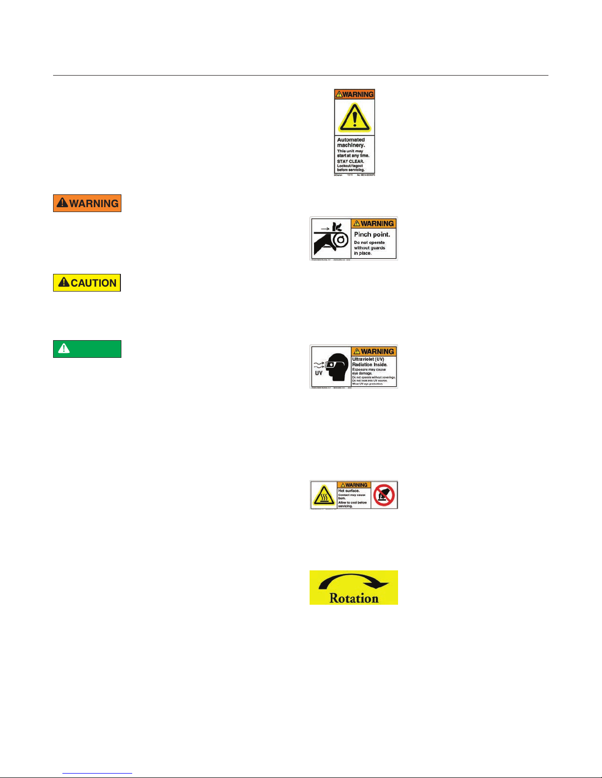
2.2 Warning and Information Labels
Warning and information labels are posted on the
Rotolter. Read labels and note their locations
before operation, maintenance, or servicing of
the product. Ultraviolet (RFUV) models contain
additional labels. Refer to the UV manual for
applicable warnings and precautions.
Automated Machinery:
This unit may start at any time.
STAY CLEAR.Lockout/tagout
before servicing.
Located on individual lid
panels
Pinch Point:
Do not operate without guards
in place.
Located on drum support
wheel nger guards
Ultraviolet (UV)
Radiation Inside:
Exposure may cause eye
damage. Do not operate
without coverings. Do not look
into UV source. Wear UV eye
protection.
Located on UV chamber
(RFUV only)
Hot Surface:
Contact may cause burn.
Allow to cool before servicing.
Located on UV module light
block shield (RFUV only)
Rotation:
Located on drive assembly
end
PR Aqua Rotolter™ Drum F ilter Installation and Operation Manual

SECTION 2: SAFETY
7
2.3 Protective Equipment
Protective equipment such
as safety glasses and hearing
protection may be appropriate
or required during installation, operation, and
maintenance of the Rotolter.
It is recommended that suitable personal protective
equipment be selected by a qualied entity prior
to installation and use of the unit. Personnel should
utilize such equipment to avoid bodily injury
or death.
2.4 Electrical Safety
Electrical hazards can cause injury
and death. Always use caution
when working near electricity.
Danger may still exist when the power is set to OFF.
All electrical work should be performed by a
qualied, professional electrician. This includes
installation, inspection, and repair of electrical
components.
A comprehensive lock-out, tag-out procedure
should be observed and followed for installation
and maintenance of the Rotolter. Lock-out/tagout procedures often exist as standard operating
procedures within company guidelines. If your
company does not employ a lock-out/tag-out
procedure, please contact your nearest workplace
safety and health administration to obtain one.
Never operate electrical equipment while you are
standing in water.
Remove power, discharge, and ground a circuit
before touching it.
2.6 Rotating Equipment
The Rotolter employs rotating
equipment, which can cause
severe injury or death. Be aware of
all rotating parts and keep body and objects away
from these areas.
Never attempt to service the unit while it is in
Automatic Mode. The drum may begin rotating
without warning when it is in Automatic Mode. The
unit should never be operated in Automatic
Mode without lids and access panels installed.
Some operation and service procedures require
rotating the moving parts. These procedures should
always be performed in Manual Mode.
Be aware of any personnel in the area when
attempting to service the unit in Manual Mode.
Do not attempt to manually rotate the drum without
rst observing the area for any personnel or objects
that may be caught in a rotating part.
Never attempt adjustments without powering off
the unit and locking out the control panel unless
otherwise specied by the service procedure.
2.7 UV Radiation
The RFUV emits ultraviolet light.
Never operate the unit without UV
module lids and covers installed.
Shut down the UV reactor prior to maintenance.
UV light can damage eyes and skin. Always wear
appropriate eye protection and protective clothing
when working on or around UV light.
When possible, work in pairs, preferably with basic
life support qualied personnel.
Personnel working with or near dangerous
voltage should be trained in modern methods
of resuscitation.
2.5 Jewelry
Remove rings, watches, chains,
and other metallic objects that
could result in shock, burns, or
may catch on equipment.
PR Aqua Rotolter™ Drum Filter Installation and Operation Manual

8
SECTION 3: SHIPPING AND STORAGE
3.1 Arrival on Site
The Rotolter is shipped fully enclosed and secured
in a wooden crate. It may be packaged as a single
unit or transferred with other system components.
UV modules for the Ultraviolet (RFUV) models
are always shipped separately because they are
extremely fragile.
There may be cardboard boxes on the oor of the
crate containing the backwash pump, plumbing kit,
or other items.
Inspect all crates for visible signs of damage before
acceptance from the shipping contractor. If damage
has occurred, the recipient should contact us
prior to acceptance in case an insurance claim
is required.
Verify the correct screen pore size from the
specication documents.
3.2 Lifting
The approximate dry and wet weights of the
Rotolters are listed below:
Molded (RFM) Models
Size Weight Dry/Wet (kg) Weight Dry/Wet (lbs)
20014 90/200 kg 190/435 lbs
32018 185/670 kg 400/1,470 lbs
32036 295/1,225 kg 650/2,700 lbs
32054 355/1,470 kg 775/3,240 lbs
48048 545/2,495 kg 1,200/5,500 lbs
48072 820/3,585 kg 1,800/7,900 lbs
60096 1,13 6 /5,545 kg 2,500/12,200 lbs
Ultraviolet (RFUV) Models
Size Weight Dry/Wet (kg) Weight Dry/Wet (lbs)
32036 545/1,955 kg 1,200/4,300 lbs
48048 1,275/4,380 kg 2,800/9,650 lbs
The Rotolter can be extremely heavy. For
mechanically assisted lifting, use an appropriatelysized lifting device capable of safely lifting the unit.
Follow proper rigging procedures at all times. Never
allow the unit to swing out of control.
Frame (RFF) Models
Size Weight Dry/Wet (kg) Weight Dry/Wet (lbs)
32018 175 / 3 65 kg 385/800 lbs
32036 190/410 kg 415/9 0 0 lbs
32054 280/475 kg 615/1,040 lbs
48048 335/685 kg 730/1,500 lbs
48072 345/910 kg 760/2,000 lbs
60072 775/1,680 kg 1,700/3,700 lbs
60096 910/2,635 kg 2,000/5,800 lbs
6012 0 1135/3,290 kg 2,500/7,250 lbs
To safely lift the unit, you should use a spreader
bar accompanied with approved nylon slings. See
Figure 2.
External or internal lifting lugs may be provided
depending upon the unit.
PR Aqua Rotolter™ Drum F ilter Installation and Operation Manual

SECTION 3: SHIPPING AND STORAGE
The minimum length of the sling should allow
the distance between the spreader bar and the
Rotolter lifting points to be 1.5 times the distance
between the lifting points. See Figure 3.
9
Figure 2. Proper lifting procedure Figure 3. Proper sling length (not to scale)
1: Lifting Lug
2: Sling (Nylon or Canvas)
3: Spreader Bar
Slings should always be made of nylon or canvas,
and should be attached to the Rotolter in one of
three ways:
• Passed through a shackle securely connected to
the lifting lug
• Passed directly through the lifting lug
• If lugs are not present, passed beneath the
underside of the frame
1: Distance Between the Lifting Points (D)
2: 1.5 Times the Distance Between the Lifting
Points (1.5 x D)
Do not attempt to lift using slings around the drum
or any plumbing ttings. Doing so will damage the
Rotolter and void the warranty.
Use a pad between the sling and the Rotolter, as
pressure from the sling may mar the surface nish
of the unit.
Rotolter Frame (RFF) models have external lifting
lugs provided on each corner of the unit, each with
a hole to provide enough room to insert a shackle
or sling.
Molded (RFM) 48-series and 60-series models
should be lifted by the support bridge at the front
of the unit, and internally-mounted lifting lugs at the
back of the unit.
Molded (RFM) 32-series models should be lifted
using two 75mm (3 in) wide slings at a minimum,
looped underneath the housing and placed as close
to each end as possible.
Ultraviolet (RFUV) models: Do not install UV
Modules until the Rotolter has been installed and
properly anchored.
PR Aqua Rotolter™ Drum Filter Installation and Operation Manual

10
SECTION 3: SHIPPING AND STORAGE
3.3 Storage
The Rotolter should always be stored on a at and
level foundation.
The Rotolter should remain in its crate until time
of installation.
The unit should always be stored in a clean, heated,
and ventilated area.
If these conditions are not available, the Rotolter
should be fully covered by a UV-treated, waterproof
material such as a tarpaulin or plastic shroud.
Provide ventilation if the unit is covered. The
ventilation should not allow moisture in and should
not be located at the top of the unit.
Condensation can occur in the Rotolter, both
during shipping and storage. Ensure that the unit
is fully dry before applying power.
Perform a systematic inspection on the Rotolter
and implement a maintenance schedule during
longer storage periods.
Actions that should be performed every 40 days if
the unit is in storage:
Actions that should be performed every 90 days if
the unit is in storage include:
Visually inspect the storage area and storage
materials for potentially damaging issues, such as
leaks in the roof or tears in the covering.
Visually inspect the Rotolter for any damage.
Add oil to the chain bath of the drive assembly for
Frame (RFF) models. Add only Clarity® Synthetic
Hydraulic Oil AW. Oil should cover the bottom links
of the chain and lower sprocket.
Perform a megger test of the electrical system, and
keep a record of insulation values, temperature,
time, humidity, and length of voltage application to
show winding conditions prior to start up. The unit
must be fully dry before applying any power.
All electrical work should be
performed by a qualied,
professional electrician.
Please contact us with any questions concerning
proper storage of the Rotolter.
Visually inspect the storage area and storage
materials for potentially damaging issues, such as
leaks in the roof or tears in the covering.
Visually inspect the Rotolter for any damage.
PR Aqua Rotolter™ Drum F ilter Installation and Operation Manual

SECTION 4: INTRODUCTION
11
4.1 Overview
Microscreen Rotolters provide an efcient means
of solids removal from water. Drum lters are widely
accepted in the treatment of water in municipal,
aquaculture, and laboratory applications.
Rotolters are intended for in-line applications.
Internal components of the Rotolter are
constructed mainly from noncorrosive stainless
steel, increasing the longevity of the product when
operated under warranty conditions.
All Rotolters are housed in an enclosure.
The Rotolter Frame (RFF) model is installed into or
above a concrete or berglass sump, which acts as
the enclosure. A sump is a low space that collects
water. Water is fed into the drum, and once treated
occupies the bottom of the sump.
The Rotolter Molded (RFM) model is housed in
molded berglass-reinforced plastic. Water is
fed into the drum, and once treated ows out of
the enclosure.
The Rotolter Ultraviolet (RFUV) model is housed in
stainless steel. Water is fed into the drum, and once
treated, ows out of the enclosure.
4.2 Location of Major Components
Listed below are the major operating components
of the Rotolter. Note: Lid panels are not shown
for illustration purposes. Appearance may vary
according to model size.
Figure 4. Major component locations -
Frame (RFF) model
1: Support Wheel Assemblies
2: Solids (Waste) Outlet
3: Inlet
4: Drive Assembly
5: Spray Bar
6: Level Control Basin (optional)
PR Aqua Rotolter™ Drum Filter Installation and Operation Manual

12
SECTION 4: INTRODUCTION
4.3 Operational Mechanics
Microscreen drum lters operate under the principle
of a mechanical sieve. Untreated water is fed to the
inside of a drum housed in an enclosure. The drum
has ne screens mounted to its periphery. Gravity
causes the water to ow through the screens, while
suspended solids within the water adhere to the
screen surface. The ltered water then ows out of
the enclosure by gravity.
In Ultraviolet (RFUV) models, the ltered water
passes through a chamber containing a series of
UV modules, each sized to deliver a specic UV
dose for disinfection, prior to exiting the enclosure.
The water level inside the drum rises as solids
collect on the screen surface and obscure the
screen pores. When the water level reaches a
contact switch, the drum begins to rotate, and a
backwash spray system is started.
The backwash spray system washes the solids
from the screens into a separate trough inside the
drum. The solids ow from the trough by gravity for
disposal or recovery.
The potential treatment capacity of the Rotolter
depends on the ow rate, solids concentration of
the water, and the pore size of the microscreen.
UV transmittance of the water is also a factor for
Ultraviolet (RFUV) models.
The Rotolter operates in Automatic Mode or
Manual Mode. When in Automatic Mode, the
backwash system and drum rotation turn on
automatically when a high-level oat switch reaches
a predetermined position. Once the drum has been
sufciently cleaned, the backwash system and
drum rotation automatically shut off.
When in Manual Mode, the backwash system and
drum rotation are always on.
Clean screens are rotated into the water, and the
water level falls. The backwash spray system shuts
down once the screens are clean. In the event
of a backwash system failure, the Rotolter has
integrated overow protection that allows water
to bypass the screens and ow directly into the
enclosure, rather than backup into the waste trough
and inlet supply.
PR Aqua Rotolter™ Drum F ilter Installation and Operation Manual

SECTION 5: PRE-INSTALLATION
13
5.1 Overview
Rotolters require physical placement, electrical
connections, and plumbing upon arrival. It is
imperative to completely follow all preinstallation
and installation instructions sequentially to
maximize the efciency and longevity of the unit.
A site will need to be established for the Rotolter
and the backwash pump. These sites will need to
be prepared prior to installation.
A qualied electrician will need to be employed to
establish electrical connections for the backwash
system and the control panel. This manual does not
detail any electrical wiring of the backwash system
or control panel.
The site will require appropriate plumbing, and the
plumbing must have ow controls to limit potential
damage to the Rotolter.
5.2 Site Requirements and Preparation
The Rotolter requires a site that is prepared
prior to installation. The site requires a level,
solid concrete installation surface with adequate
service clearance.
Molded (RFM) and Ultraviolet (RFUV) models
require a solid, level concrete foundation. Section
5.3 of this chapter contains appropriate information.
Frame (RFF) models require a solid, level foundation
within a sump. Sumps should be composed of
solid concrete or berglass. Rotolters may
need to be installed inside the sump or directly
above it. Section 5.4 of this chapter contains
appropriate information.
Minimum service access is required for regular
maintenance of the Rotolter. Access is required on
the inlet, drive assembly, and spray bar assembly
sides of the unit.
Some maintenance procedures require the
Rotolter to be dry. To perform these procedures,
Frame (RFF) models will need to have sumps that
can be drained or pumped. Molded (RFM) and
Ultraviolet (RFUV) models have integrated drains in
their enclosures.
Inlet and outlet water levels coming to and going
from the site must be controlled for the Rotolter to
function properly, and to avoid damage to the unit.
The Rotolter does not supply external controls for
these levels.
External water source access, such as access
to a municipal water supply, may be needed if
the backwash system will not use the unit's
ltered discharge.
Electrical sources are required for the backwash
system and control panel.
5.3 Foundation and
Service Access Requirements
Rotolter Molded (RFM) and Ultraviolet (RFUV)
models must be placed on a solid, at, and level
concrete foundation with adequate service access
to the inlet, drive assembly, and spray bar assembly
sides of the unit. The technical specication
documents detail which side of the Rotolter is the
service access side (left or right, when facing the
inlet).
The location of the foundation should be
determined based on service access and stability.
Minimum recommended service access is 92
centimeters (36 inches).
PR Aqua Rotolter™ Drum Filter Installation and Operation Manual

14
SECTION 5: PRE-INSTALLATION
A layer of self-leveling concrete should be applied
to the foundation and the consistency of the level
should be conrmed prior to Rotolter installation.
Once this layer is applied, check that the foundation
surface does not differentiate more than 6.4
millimeters (0.25 inches) across the entire area.
Places that exceed this difference should be ground
down to prevent stress points from forming. The
berglass housing of Molded (RFM) models can
fracture from stress points. Stress points can also
cause damage to Ultraviolet (RFUV) units.
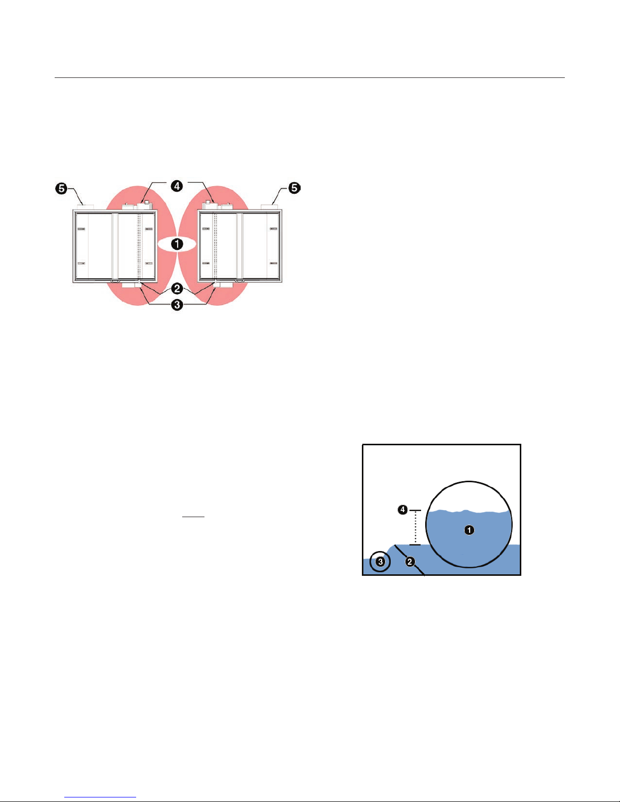
Figure 5. Minimum service clearance for right
(standard) and left service access units
1: Minimum Service Access (red area) - 96
centimeters (36 inches)
2: Spray Bar Assembly (can be connected at
opposite end)
3: Inlet (location may vary)
4: Drive Assembly and Motor
5: Outlet (location may vary)
Service access is required daily. The following are
some of the functions that require service access:
• Water level inspection
• Spray bar nozzle cleaning
• Inspection and maintenance of screen panels
• Inspection and maintenance of support wheels
5.4 Sump Requirements
Rotolter Frame (RFF) models should be installed in
or above concrete or berglass sumps, with service
access to the inlet, drive assembly, and spray bar
assembly sides of the unit.
Due to the high variation between Rotolter
congurations, this manual does not detail
sump creation. The following are guidelines for
consideration.
The sump should include (at a minimum) an inlet,
outlet, drain, and waste channel. An additional
channel may be required for overow protection.
Dimensions of required channels can be
determined from the technical specication
documents. Contact us with questions.
The Rotolter requires a minimum operating water
level, which can be controlled through a weir
integrated into the sump. Alternately, a level control
basin may be included on a Frame (RFF) unit, the
top edge of which acts as the level control.
• Inspection and maintenance of drum seal
• Inspection and maintenance of drive assembly
• Scheduled cleaning
The foundation must be sturdy, as the weight of
the Rotolter can be extremely heavy when in
operation. The weight of the unit is listed on the
technical specication documents, or see Rotolter
weights in Section 3.2
The area must be at and level. Operating the
Rotolter on an unleveled surface will cause
irreversible damage to the internal components,
will cause the unit to malfunction, and will void
the warranty.
PR Aqua Rotolter™ Drum F ilter Installation and Operation Manual
Inlet and outlet channels must have fully functional
ow controls located at or near the unit. These
controls will be described in the following section.
In the event of a backwash system failure, unltered
water will bypass the screens and ow directly into
the enclosure via the integrated overow weir of the
Rotolter. If unltered water can not be permitted to
enter the outlet water channel, an overow channel
upstream of the lter inlet should be included in the
sump design.
Some maintenance procedures require the
Rotolter to be dry. To perform these procedures,
Frame (RFF) models will need to have sumps that
can be drained or pumped.
SECTION 5: PRE-INSTALLATION
15
The bottom of the sump must be a solid, level
foundation. The location of the sump should be
determined based on service access and stability.
Minimum recommended service access is 92
centimeters (36 inches) on the inlet, drive assembly,
and spray bar assembly sides.
Figure 6. Minimum service clearance for right
(standard) and left service access units
1: Minimum Service Access (red area) - 96
centimeters (36 inches)
2: Spray Bar Assembly (can be connected at
opposite end)
The area must be at and level. Operating the
Rotolter on an unleveled surface will cause
irreversible damage to the internal components,
will cause the unit to malfunction, and will void
the warranty.
A layer of self-leveling concrete should be applied
to the foundation and the consistency of the level
should be conrmed prior to Rotolter installation.
Once this layer is applied, check that the foundation
surface does not differentiate more than 6.4
millimeters (0.25 inches) across the entire area.
5.5 Hydraulic Controls
The Rotolter has no external ow controls,
therefore the inlet and outlet channels connected
to the unit must have fully functional ow controls
located at or near the unit. These controls should
be installed prior to installation of the Rotolter. The
type of controls will depend on the inlet and outlet
channels at the installation site.
Control of the inlet and outlet water levels are
critically important to maintaining proper water
levels inside and outside of the Rotolter. These
water levels should never exceed the limits
identied by Pentair.
3: Inlet (location may vary)
4: Drive Assembly and Motor
5: Outlet (location may vary)
Service access is required daily. The following are
some of the functions that require service access:
• Water level inspection
• Spray bar nozzle cleaning
• Inspection and maintenance of screen panels
• Inspection and maintenance of support wheels
• Inspection and maintenance of drum seal
• Inspection and maintenance of drive assembly
• Scheduled cleaning
The foundation must be sturdy, as the weight of
the Rotolter can be extremely heavy when in
operation. The weight of the unit is listed on the
technical specication documents, or see Rotolter
weights in Section 3.2
Figure 7. High water level differential inside
and outside of the drum
1: Water Level Inside Drum
2: Outlet (Level Control) Weir
3: Outlet
4: Water Level Differentia
PR Aqua Rotolter™ Drum Filter Installation and Operation Manual

16
SECTION 5: PRE-INSTALLATION
Problems that may occur if water levels are not
controlled include:
Damage to the Rotolter screens, drum shaft,
support wheels, and drum frame, due to excessive
weight caused by a high differential between water
levels inside and outside of the drum. The warranty
will be voided if the difference is greater than 30.5
centimeters (12 inches).
Reduced drum shaft bearing life, due to frequent
or constant submergence from a high outlet
water level.
Tray sludge may reenter the lter or may bypass the
lter and enter the outlet water, due to water owing
into the backwash tray of the lter from a high inlet
water level.
The above problems will result in reduced
operating range of the lter, which may cause
more frequent or continuous backwash, and will
reduce lter performance.
Continuous monitoring of the inlet and outlet
water levels (e.g., using a level transducer)
is recommended, but may not be suitable or
necessary in all applications.
• Inlet water levels should be continuously
monitored regardless of application if large
variations in ow are anticipated or could occur.
• Outlet water levels should be monitored if the
Rotolter does not have a low/high water level
alarm switch or automatic backwash system.
An outlet (level control) weir is necessary to
maintain a minimum water level inside the unit
to prevent damage. Rotolter Molded (RFM) and
Ultraviolet (RFUV) models contain integrated level
control weirs that help maintain the minimum water
level required inside of the drum. Frame (RFF)
models utilize one of two level control methods:
a weir integrated into the lter sump design, or a
level control basin installed on the underside of the
Roto lter.
A high overow weir is necessary to protect the
drum in the event of a backwash system failure.
The overow weir allows unltered water to bypass
the drum screens at critical levels and ow directly
into the outlet. Rotolters contain integrated
overow weirs. If overow directly into the outlet
is unacceptable, RFM and RFUV units will require
additional plumbing upstream of the lter. RFF units
will require an overow channel integrated into the
sump.
5.6 Backwash System Considerations
The backwash system requires a water supply, an
electrical supply, a xed pump location, and proper
plumbing.
5.6.1 Water Supply
The water supply may come directly from the
Rotolter or may need to come from an external
source. This depends predominantly on the water
quality requirements of the Rotolter application.
Some applications require highly ltered or puried
water. If water quality is not an issue, a source may
be selected based on the desired frequency of
maintenance.
The backwash system can be plumbed directly into
the ltered water supply of the Rotolter. Water
coming directly from the unit has been ltered, but
is not puried and contains dissolved nutrients that
will support bacterial growth.
This growth, combined with accumulations of ne
particles and deposition of dissolved minerals,
can cause the backwash system to foul over
time. Increased fouling will require more frequent
maintenance.
More stringent water quality requirements will
necessitate plumbing to an external water source.
Municipal water supplies generally do not contain
higher concentrations of dissolved nutrients and
ne particles, reducing the degree of fouling over
time.
PR Aqua Rotolter™ Drum F ilter Installation and Operation Manual
Check with the local water supplier for quality
parameters. Pressure and ow rates from external
water sources should meet the values required for
the Rotolter, as specied by Pentair.
SECTION 5: PRE-INSTALLATION
5.6.2 Electrical Supply
The electrical supply requirements depend on the
pump supplied with the Rotolter. The separate
pump manual will identify the supply requirements.
The backwash system electrical supply should be
diagrammed prior to lter installation.
All electrical work should
be performed by a
qualied electrician.
All dimensions and locations should be checked
for accuracy and changes should be made if any
part of the backwash system will interfere with the
service clearance required by the Rotolter.
5.6.3 Pump Location
The pump should be anchored near the Rotolter.
The pump can be placed above the lter, but a foot
valve (not included) may need to be installed to
prevent loss of prime due to back ow.
17
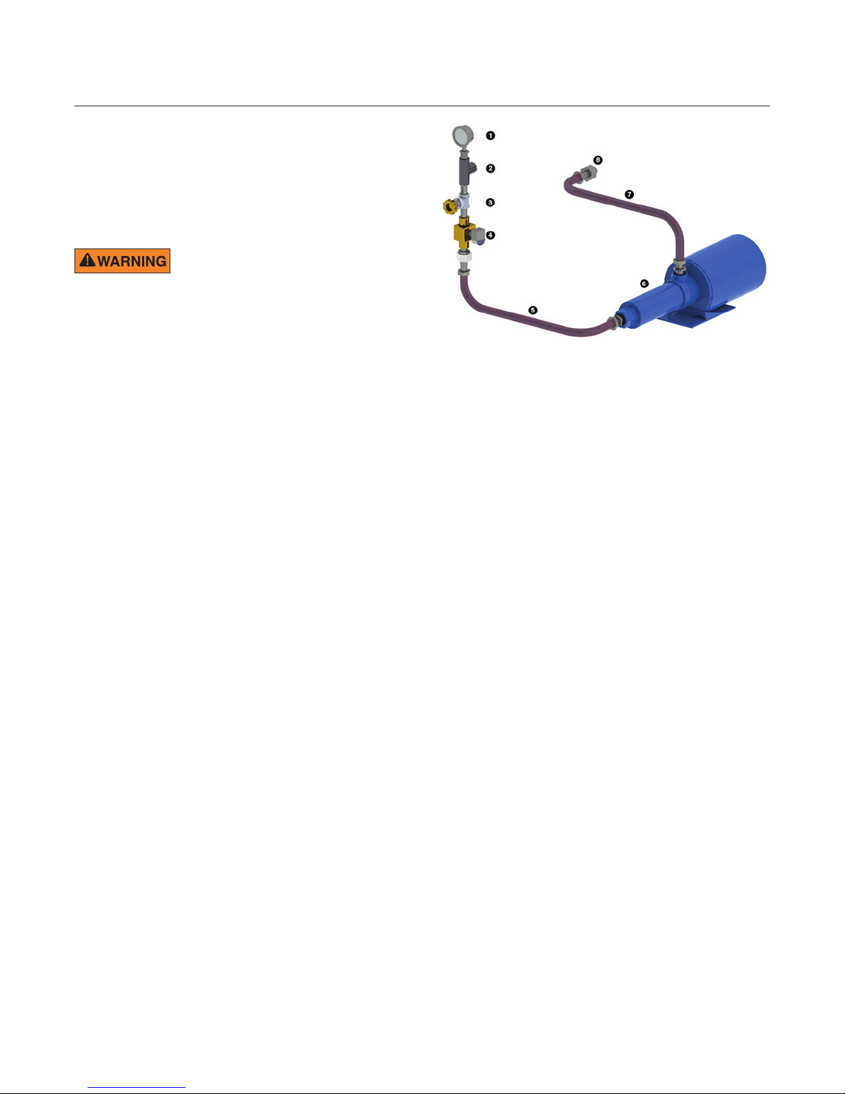
Figure 8. General backwash system assembly
1: Pressure Gauge
2: Connection Point (to Spray Bar Assembly)
3: Throttling Valve
The pump location should allow for the pump to be
securely attached, allow ample room for plumbing
and electrical xtures, and should not interfere with
the service clearance required by the Rotolter.
5.6.4 Proper Plumbing
The backwash system is shipped with ttings,
gauges, and valves. Plumbing xtures are
not included.
The backwash system plumbing should be
diagrammed prior to lter installation. All plumbing
dimensions and locations should be checked for
accuracy and changes should be made if any part
of the backwash system will interfere with the
service clearance required by the Rotolter.
If the backwash plumbing or pump will be
outside or partially outside, it must be insulated
to prevent freezing.
4: Solenoid (if Required)
5: Outlet Plumbing (Pump to Unit)
6: Backwash Pump
7: Inlet Plumbing (Source to Pump)
8: Connection Point (to Source)
A pressure gauge, throttling valve, and solenoid
valve (if required) will need to be connected to
the spray bar. This assembly can be connected
on either end of the spray bar. A solenoid valve is
required where the supply water is pressurized or
where the pump is located above the water supply
or discharge level.
The pressure assembly should be connected at the
Rotolter. See Figure 8.
The water supply should be connected to the
inlet of the pump. For Frame (RFF) models, the
pump inlet should be connected to a supply that is
completely submerged in the sump.
PR Aqua Rotolter™ Drum Filter Installation and Operation Manual

18
SECTION 5: PRE-INSTALLATION
5.7 Control Panel Considerations
Most Rotolters are purchased with a control panel.
This manual describes operation and maintenance
procedures for units that utilize a control panel. If
a control panel was not ordered with the Rotolter,
one may be ordered at any time.
The control panel allows toggling between
Automatic Mode, Manual Mode, and Off for the
drum rotation and backwash systems. The panel
also displays Power-On and Unit-Run conditions.
The control system is made from high-quality,
industrial-grade, CSA- and UL-approved
components. The control panel box is a waterproof,
corrosion-proof CSA- and UL-approved electrical
enclosure that can be secured with padlocks. The
control panel assembly is manufactured in a ULcertied facility, and should not be modied. Any
modication voids the UL rating.
The control panel should always be installed within
line of sight of the Rotolter. If this is not possible,
disconnects for the drum motor and backwash
pump system must be installed next to the
Rotolter as a safety precaution. The control panel
door should be able to open fully.
All electrical work should
be performed by a qualied
electrician. This manual does
not provide electrical installation procedures
or wiring diagrams.
The control panel installation location should
be outlined and diagrammed prior to Rotolter
installation. The location should allow ample room
for electrical xtures and should not interfere with
the service clearance required by the Rotolter.
5.8 Electrical Power Requirements
The electrical power requirements for the Rotolter
motor and backwash pump are listed in the
Technical Specication sheet sent prior to
Rotolter arrival.
All electrical work should
be performed by a qualied
electrician. This manual does
not provide electrical installation procedures
or wiring diagrams.
5.9 Flushing Plumbing
The plumbing that will be connected to the
Rotolter should be thoroughly ushed prior
to Rotolter installation. Flushing the plumbing
removes debris that could damage the screens and
internal components of the Rotolter.
All removed material should be collected and
disposed of properly.
To ush a system, the discharge valve should be
opened rst, then the charge valve. Flush for at
least 2 minutes. If there are multiple circuits within
a system, ush one full circuit at a time, each for at
least 2 minutes.
To prevent potentially dangerous pressure buildup,
open the next circuit discharge valve before closing
the preceding discharge valve. When all plumbing
has been ushed, shut off the charge valve rst and
then shut off discharge valves.
PR Aqua Rotolter™ Drum F ilter Installation and Operation Manual

SECTION 5: PRE-INSTALLATION
19
5.10 Pre-Installation Checklist
Be sure the following items are completed prior to
beginning installation.
Site foundation is at and level.
Sump is complete with all necessary channels
(RFF models only).
Rotolter will have at least 92 centimeters (36
inches) of service access on the inlet, spray bar
assembly, and drive assembly sides.
Inlet water channel has fully functioning ow
control capable of maintaining level identied
by Pe ntair.
Inlet water channel has monitoring system
installed (if necessary).
Appropriate connections are available and can
be made between the inlet water channel and the
Rotolter inlet.
Outlet water channel has fully functioning ow
control capable of maintaining level identied
by Pe ntair.
Appropriate connections are available and can be
made between the outlet water channel and the
Rotolter outlet.
Appropriate connections are available and can
be made between the overow channel and the
Rotolter overow weir (if necessary).
Backwash pump water source has
been identied.
Backwash pump electrical supply has
been identied.
Backwash electrical system has been outlined,
diagrammed, checked for accuracy, and will
not interfere with the service clearance of the
Roto lter.
Backwash plumbing system has been outlined,
diagrammed, checked for accuracy, and will not
interfere with the service clearance of
the Rotolter.
Control panel location has been identied,
outlined, diagrammed, and will not interfere with
the service clearance of the Rotolter.
Outlet water channel has monitoring system
installed (if necessary).
Existing plumbing has been thoroughly ushed.
PR Aqua Rotolter™ Drum Filter Installation and Operation Manual

20
SECTION 6: INSTALLATION
6.1 Tools Required
Flathead screwdriver
Phillips screwdriver
SAE hex key (Allen) wrench set
Socket wrench
SAE socket set
SAE open-end wrench set
Rubber and machinist hammer (deadblow
hammer)
Carpenter’s level
Measuring tape
Crescent wrench
Thread seal tape, or food-grade thread sealant
Anti-seize paste (food-grade or equivalent)
6. Measure the available service clearance on the
inlet, drive assembly, and spray bar assembly
sides of the Rotolter. Move the unit if clearance
is not adequate.
7. Use a carpenters level on all sides and top of the
Rotolter to ensure the unit is level. See Figure 9.
Figure 9. Leveling the Rotolter
6.2 Installing the Rotolter
Once the Pre-Installation Checklist (Section 5.10) is
complete, the Rotolter is ready to be installed.
1. Remove the top and sides of the shipping crate
from around the unit.
2. Remove the lag screws securing the unit anchor
brackets to the bottom of the pallet.
3. Remove lids from top of the unit.
4. Secure appropriate rigging to the Rotolter and
the lifting device. Refer to Section 3.2 for proper
lifting procedures. Lift the unit until the bottom
portion of the shipping pallet can be removed.
Rotolters can be extremely heavy.
For mechanically assisted lifting,
use an appropriately-sized lifting
device capable of safely lifting the unit. Follow
proper rigging procedures at all times. Never allow
the unit to swing out of control.
5. Lower the unit until it rests on the installation
location, but do not remove the lifting rigging.
Ensure the inlet, solids, and overow (if required)
channels align properly with the external
plumbing for Molded (RFM) and Ultraviolet
(RFUV) units, and sump channels align with
Frame (RFF) units.
1: Level the Rotolter from Side to Side
2: Level the Rotolter from Front to Back
If the unit cannot be leveled, another layer of
self-leveling concrete should be applied to the
installation location and allowed to set. Place the
Rotolter on the foundation and test for level again.
If a Frame (RFF) model remains unleveled, solid,
immobile stainless steel shims can be inserted
under the lower corner posts of the unit. Shims
should be used only if the installation location
cannot be leveled using the procedure listed above.
Do not attempt to use shims for Molded (RFM) or
Ultraviolet (RFUV) models.
Most models will need to be secured to the
installation location using the anchor brackets and
appropriate fasteners. The unit should be anchored
using sheer load-bearing hardware that is rated to
8 times the wetted weight of the Rotolter. Use a
hammer drill and always blow out the holes prior to
inserting hardware.
PR Aqua Rotolter™ Drum F ilter Installation and Operation Manual
 Loading...