


Sigma Delta

Sigma Delta Vaporizer
Service Manual
Quality and Assurance in Anaesthesia

Servicing and Repairs
In order to ensure the full operational life of
the Sigma Delta vaporizer, we recommend
that a periodic service check should be
performed by a Penlon trained engineer.
This check comprises a vaporizer LEAK
TEST and CALIBRATION CHECK.
Note:
(a) The calibration check must be performed
using a suitable agent analyser, e.g. a Riken
refractometer or infrared analyser.
(b) The service check is part of the
recommended pre-use check for your
Anaesthesia System.
Should the calibration checks show the unit
to be outside the specified performance
requirement, then an overhaul service must
be performed.
This may be done on site by:
(a) A trained user.
(b) An authorised Penlon agent.
(c) A Penlon service engineer.
A calibration and service record section is
provided in the user instruction manual to
maintain a record of the vaporizer's
performance.
For any enquiry regarding the service or
repair of this vaporizer, contact the nearest
accredited Penlon agent* or contact the
Service Department at Penlon Limited.
Service and Repair Department
Penlon Ltd
Abingdon
OX14 3PH
UK
Tel: +44 (0) 1235 547063
Fax: +44 (0) 1235 547062
E-mail: service@penlon.co.uk
Always give as much of the following
information as possible:
1. Type of equipment
2. Product name
3. Serial number
4. Approximate date of purchase
5. Apparent fault
IMPORTANT
(i)

This manual has been produced to provide
authorised personnel with information on the
function, routine performance, maintenance
checks and repairs, applicable to the Penlon
Sigma Delta vaporizer.
Information contained in the manual is correct at the date of publication. The policy of
Penlon Limited is one of continued improvement to its products. Because of this policy
Penlon Limited reserves the right to make
any changes, which may affect instructions
in this manual, without giving prior notice.
Personnel must make themselves familiar
with the contents of this manual before using
the vaporizer.
Terminology
This manual complies with ISO 4135,
Anaesthetic Apparatus Terminology.
The following additional definitions should be
noted:
Vol.% - shortened form of volumetric per-
centage.
The commonly used method of expressing
vapour concentrations so that they can be
compared with concentrations of true gases.
100 Vol.% is equivalent to 100% partial pressure in a mixture.
Copyright © Penlon Ltd, 2002
FOREWORD
(ii)

CONTENTS
User Responsibility 1
1. Warnings and Cautions 2
2. Purpose 4
3. Description 7
4. Specification 11
5 Service Procedures 12
5.1 Service Policy 12
5.2 Workplace and Equipment 14
5.3 Pre-Service Checks 18
5.3.1 Leak Test, Bypass Resistance Check (before servicing) 18
5.3.2 Fault Finding (before servicing) 19
5.4 Service Overhaul 21
5.4.1 General Information 21
5.4.2 Health and Safety 21
5.4.3 Service Overhaul Procedure 22
5.4.4 Leak Test, Bypass Resistance, and Calibration Check (after servicing) 64
6 Parts List 68
(iii)
(iv)


This vaporizer has been built to conform with
the specification and operating procedures
stated in this manual and/or accompanying
labels and notices when checked. assembled, operated, maintained and serviced in
accordance with these instructions provided.
To ensure the safety of this vaporizer it must
be checked and serviced to at least the minimum standards laid out in this manual.
A defective or suspected defective, product
must not, under any circumstances be used.
The user must accept responsibility for any
malfunction which results from non-compliance with the servicing requirements
detailed in section 8.1.
Worn, broken, distorted, contaminated or
missing components must be replaced
immediately. Should such a repair become
necessary it is recommended that a request
for service advice is made to the nearest
Penlon service centre,
This vaporizer and any of its constituent
parts must be repaired only in accordance
with written instructions issued by Penlon
Limited, and must not be altered or modified
in any way without the written approval of
Penlon Limited.
The user of this equipment shall have the
responsibility for any malfunction which
results from improper use, maintenance,
repair, damage or alteration by anyone other
than Penlon Limited or its appointed agents.
This vaporizer must only be supplied to, and
used by, suitably qualified medical practitioners.
Caution: USA and Canadian Federal Law
restricts the sale and use of this device by or
on the order of a physician.
Statements in this manual preceded by the
following words are of special significance.
WARNING - means there is a possibility
of personal injury to yourself or others.
CAUTION - means there is a possibility of
damage to the instrument or other property.
NOTE - indicates points of particular interest
for more efficient and convenient operation.
The reader must take particular notice of the
warnings, cautions,. and notes printed
throughout the manual.
USER RESPONSIBILITY
1

WARNINGS
1. The Sigma Delta vaporizer is to be
sold to, and used on the order of, a
medically qualified practitioner
only.
2. Anaesthetic agents are poisonous,
and inhaling their vapours, even in
low (sub-anaesthetic)
concentrations may present a
health hazard.
Care must be taken to avoid
spillage of anaesthetic drugs when
filling or draining the vaporizer.
3. The procedures described herein
which involve dismantling the
vaporizer must only be performed
after the instrument has been
drained and dried out.
4. Calibration procedures must only
be performed with the vaporizer
outlet connected to an anaesthetic
gas scavenging system designed
in accordance with national
standards or regulations.
5. No oil or grease should be
permitted in the vaporizer service
area.
This applies equally to silicone
based lubricants, flammable oil,
and grease.
6. The Sigma Delta vaporizer is
designed for use only with one
anaesthetic agent - that which is
named on the filler block.
Misdosage will occur if the
vaporizer is filled with the wrong
drug.
Keyed filler devices are provided
on certain models to meet national
and international standards.
7. The Sigma Delta vaporizer must not
be modified or disassembled by
any unauthorised person. It should
be regularly serviced by a Penlon
authorised service agent, trained
technician or engineer and by no
other person (see section 6).
8. The pharmacopoeia name of the
drug is used on the label according
to BP, USP or Ph EUR.
The user is responsible for
confirming that any trade name of a
drug is equivalent to the registered
name.
9. Violent movement or tipping of a
filled vaporizer may cause liquid
agent to leak into the control
mechanism and subsequently
deliver uncontrolled doses of
vapour.
The vaporizer must be empty, and
the control must be in the zero
position during transport.
The vaporizer must be purged at
maximum output with 5 L/min flow
of oxygen for 2 minutes, and the
output checked with an analyser
prior to use.
10. The vaporizer control must be in
the zero position during the filling
or draining process. Delivered
concentrations are inaccurate
while the standard filler port is
open or the key filler shoe loose.
The vaporizer must be upright
during filling, to prevent overfilling.
11. Vaporizers may malfunction if
exposed to excessively high
temperatures, e.g. by storage
above a radiator. This may
permanently damage the vaporizer.
Maximum storage temperature:
50oC (122oF)
Minimum storage temperature:
-20oC (-5oF).
12. Vaporizer outputs are sensitive to
barometric pressure and a
correction factor may be necessary
when assessing the output using
an analyser, for example at high
altitude. Barometric pressure
effect are not usually of clinical
importance. (See user manual).
1. WARNINGS AND CAUTIONS
2

13. Anaesthetic drugs must be treated
as a pharmaceutical product.
Liquid should never be drained
from a vaporizer into an open
container and then reused.
Contamination is likely.
Always dispose of such drained
liquid as a hazardous chemical.
CAUTIONS
1. The instructions given in this manual
assume that the service engineer has
received adequate training in the
practice of servicing anaesthetic
apparatus and is familiar with the use
of flowmeters, pressure gauges and
other laboratory equipment.
Details of such procedures are
therefore not
included.
2. Each Sigma Delta vaporizer is a
tested and calibrated unit. It is most
important that components are not
transferred from one unit to another.
In particular, the service engineer
must accept responsibility for
ensuring that agent specific items
such as labelling, keyed fillers, and
control needles are treated as critical
devices and that full records of
vaporizer servicing are kept.
Following any service procedure, a
label to indicate to clinical staff that
the vaporizer has been serviced must
be attached to each unit.
WARNINGS AND CAUTIONS
3

2. PURPOSE
The Sigma Delta vaporizer is designed for
incorporation in the fresh gas supply system
of continuous flow anaesthetic machines,
directly connected between the flowmeter
unit and the common gas outlet of the
machine.
The vaporizer is unsuitable for use within a
breathing system 'in circuit' because of the
relatively high internal resistance.
Its purpose is the provision of accurate
concentrations of anaesthetic drugs in the
fresh gas supply, in accordance with the
setting of the control dial, when the fresh gas
supply flow is between 0.2 and 15 litres/min.
Factors affecting output accuracy are listed
in the user instruction manual (Section 7,
Performance Characteristics), which shows
the extent of modifications to the control calibration.
4
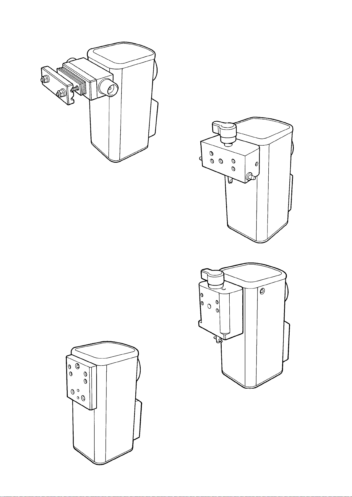
5
Cagemount
Selectatec
Drager
North
American
Drager
Delta Vaporizer
Connector Block Types

6
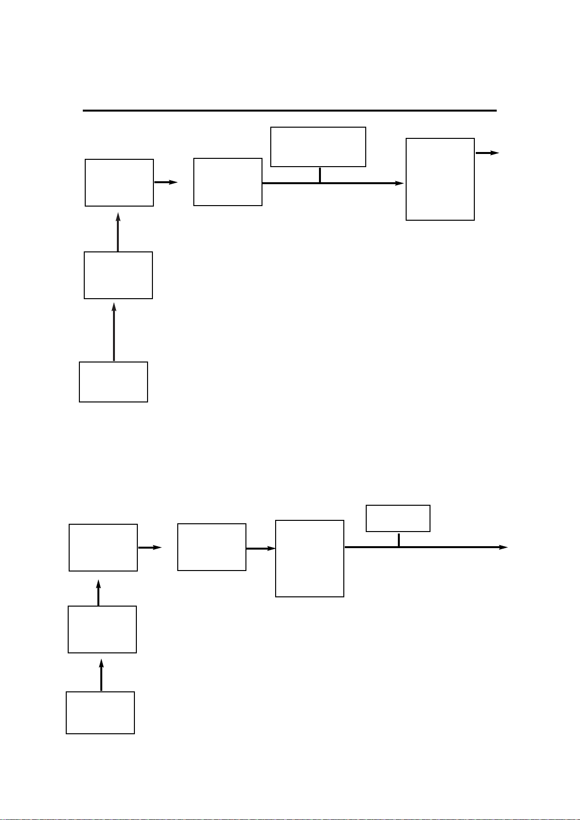
Figure 1
Gas Flow Path

Closing
mechanism
(On/off control)
Vapour
concentration
control needle
Temperature
compensator chamber
Spiral
passage
Vapour
chamber
Mixing
chamber
Gas
Flow
Out
Bypass
Flow
Saturated
vapour
Gas
Flow
In
3.1 General Description
The Delta User Manual provides additional
information on the operation of the vaporizer. The
service engineer should have a copy for
reference, in addition to this service manual.
Introduction
The Sigma Delta vaporizer enables the
anaesthetist to add a predetermined amount
of vapour of a volatile drug to the fresh gas
stream supplied to the patient’s breathing
system.
All anaesthetic agents of a volatile nature
have relatively high vapour pressures at
normal room temperature so that this
saturated vapour must be diluted
considerably to produce the concentrations
required clinically.
Gas Flow Path
Figures 1 and 2 show that the vaporizer
contains two paths for gas flow. One is
always open, through the bypass system.
The second, which is open only when the
control knob is moved from zero, is routed
via the closing mechanism vapour chamber,
and, vapour control orifice, and joins up with
the bypass flow in a mixing chamber, and
then on to the vaporizer outlet.
Vapour Chamber
The vapour chamber contains the liquid
anaesthetic drug, and is filled through the
filler unit to a level shown on the level
indicator. The chamber contains a spiral
wick assembly.
Gas which enters the chamber has to pass
through the narrow passages between the
wicks, becoming saturated with vapour
before emerging through the vapour control
orifice.
The proportion of the total flow which passes
through the vapour chamber is determined
by the relative resistances of the bypass
orifice (which does not vary with control knob
setting, but does vary with temperature) and
the vapour control orifice (which varies only
with control knob setting).
Compensation for total flow variation is
achieved by the design of the orifice
elements which are precision parts.
Temperature Compensation
Compensation for temperature variation
(and therefore changes in vapour pressure,
viscosity etc.) is achieved by the movement
of a bypass control plate (in the form of a
bimetallic strip) against the bypass orifice,
thus changing the area of the orifice. This
device is mounted within the vapour
chamber so that it is exposed to both gas
and liquid temperatures within the vaporizer.
Back-pressure Compensation
Compensation for fluctuating back-pressure
on the vaporizer, as produced by the use of
IPPV in the breathing system, is provided by:
A) the inclusion of a long gas flow path
prior to the closing mechanism system, and
B) a spiral passage after the closing
mechanism,
which prevents reverse flow of vapour from
the chamber into the bypass gas flow.
3. DESCRIPTION
Figure 2
Gas Flow
Block Diagram
7

3.2 Concentration Control
and Cut-off Mechanism
3.2.1 Control Knob Assembly
The laser engraved dial is etched to match the
performance characteristics of the components
of the individual vaporizer using its allotted
agent.
A self-adhesive label, colour coded for the
agent to be used with the vaporizer, is fixed to
the knob.
3.2.2 Dial Stop Plate Assembly
and Vapour Control Valve
When the control knob is pushed in, the dial
drive plate disengages from the zero position
dial stop (which prevents knob rotation in the
zero (off) position), and opens the closing
mechanism by pushing on the shaft assembly
(see 3.2.4).
The stop plate is now disengaged from the dial
stop and it is free to turn anti-clockwise. A drive
screw produces movement of the vapour
control needle valve within the needle housing,
altering the size of the orifice available for the
passage of vapour.
3.2.3 Dial Stops
The dial stop (zero position) prevents rotation
of the knob assembly in the zero position.
3.2.4 Cut-off Mechanism
When the control knob assembly is in the zero
position, the spring-loaded cut-off valve is
closed. This prevents gas flowing into the
vapour chamber.
When the control knob assembly is pushed in,
the closing mechanism shaft pushes a spring
loaded seal off its seat on a spool assembly.
Gas is then able to flow into the vapour
chamber.
3.2.5 Interlock Mechanism
With two or three interlocked vaporizers on the
anaesthetic machine back bar, initial operation
of the concentration control dial, by pushing on,
activates the interlock system. The interlock
push rods move outwards, ensuring that only
that vaporizer can be in use at any time.
The interlock deactivates as soon as the control
dial is returned to the zero position.
DESCRIPTION
8
Selectatec
Interlock

3.3 Temperature
Compensator (TC)
This device alters the resistance to the flow of
gas passing through a bypass valve.
The temperature sensitive element comprises a
bimetallic assembly that expands/contracts with
increase/decrease in temperature, causing the
bypass plate to move away from, or towards the
TC base.
At low temperature the bypass resistance is
increased, forcing more gas through the vapour
chamber to compensate for the lower vapour
pressure of the liquid. At high temperatures the
reverse is effected.
3.4 Wick Assembly
The large wick assembly consists of a long strip
of wick material attached to a metal backing
strip, and rolled into a spiral. This forms a single unit cartridge assembly for ease of replacement.
9
DESCRIPTION
3.5 Filler Systems and
Agent Level Indicator
3.5.1 Agent Specific (Keyed) Filler
This unit is designed to be used with a bottle
adaptor only - refer to the vaporizer user
manual.
Bottle adaptors for each agent type are
available - see section 10, in the user instruction
manual.
3.5.2 Screw Cap Pour Filler
This unit has a screw-plug, sealed filler opening.
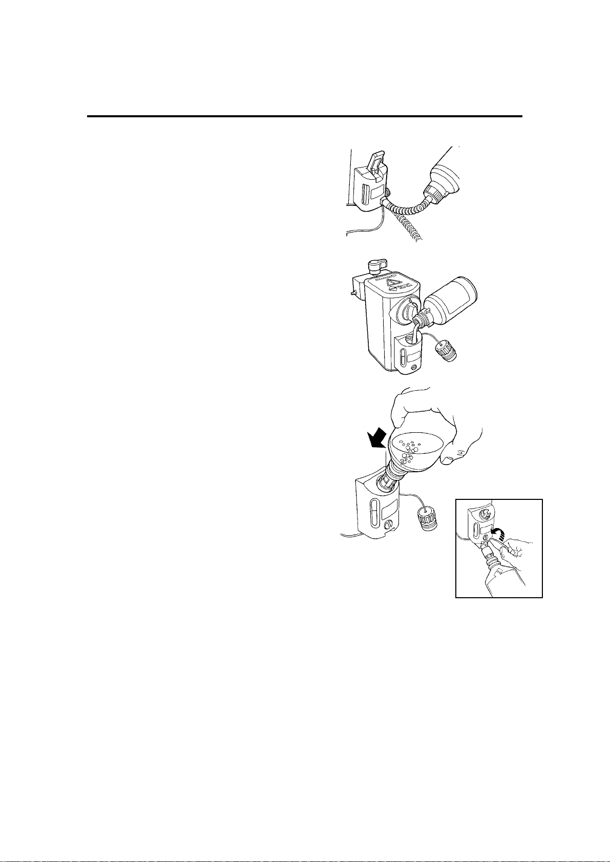
3.5.3 Quik-Fil Filler
This unit is designed to be used with an agentspecific nozzle, permanently attached to the
agent bottle.
When the nozzle is inserted into the filler block,
a valve opens inside the filler block.
When the nozzle is pressed further into the filler
block, a valve in the nozzle opens and agent
flows into the vaporizer.
The filler block utilises an air lock which
automatically stops the filling process at the
maximum fill position.
The vaporizer is drained through a separate
valve in the base of the filler block.
3.5.4 Agent Level Indicator
The level indicator is a glass tube with
maximum and minimum fill level marks printed
on the glass.
Provided the vaporizer is upright, with the
control knob set at zero, the chamber cannot be
overfilled as the design of the air escape ports
facilitates air trapping at the maximum safe
level.
On agent specific (keyed) filler models, an
overfill hole drains excess agent from the filler
system.
On screw cap filler models, a drain hole is
included in the side of the filler block to drain the
filler funnel level should excess agent be tipped
into the filler block during filling.
10
DESCRIPTION

4. SPECIFICATION
11
4.1 Physical Dimensions
Width Height Depth
Cagemount 133 219 158
Selectatec Compatible with Interlock 120 242 190
Drager 'plug in' Compatible 100 242 190
Dimensions given above are in millimetres
NOTE
The figures for Depth relate to Key Filler (Agent Specific) and Quik Fil models.
To calculate the depth dimension for Screw Cap Filler models, subtract 11 mm from the figures given above.
4.2 Weight
Approximate weight: 4.8 kg.
4.3 Capacity
Volume at MAX mark 250 ml (nominal)
Volume at MIN mark 35 ml (nominal)
NOTE After draining, approximately 60 ± 10 ml of liquid is retained by the wick.
4.4 Filling System
Key Filler (Agent Specific)- Use with corresponding agent specific filler adaptor, see section 10 (USER
Manual), Ordering Information.
Pour Fill (Screw Cap)
Quik Fil - Sevoflurane only -
Use with corresponding agent specific bottle.
4.5 Control Dial Scale
The control dial is marked as follows:
From 0 to 2% vol, by intervals of 0.2% vol
From 2% to maximum, by intervals of 0.5% vol
The control dial is marked '0' at zero
4.6 Patents
The Sigma Delta is protected by UK and foreign patents.
4.7 Temperature Range
Operating Temperature Range 15 to 35oC (58 to 95oF)
Storage Temperature Range -20 to 50oC (-5 to 122oF)
Storage in Transit (up to 7 days) -40 to 60oC (-40 to 149oF)
4.8 Flow Range
Operating Flow Range: 0.2 to 15 litres/min.
See section 7.4.1 (User Manual) for output accuracies at extreme conditions.
4.9 Pressure Range
Operating Pressure Range 0 to 5 kPa (0 to 0.7 psi)
Maximum Manifold Pressure 38 kPa (5.5 psi)
Maximum Test Pressure 38 kPa (5.5 psi)

5. SERVICE PROCEDURES
5.1 Service Policy
The Sigma Delta must only be serviced at an authorised
service centre or by Penlon-trained technicians in
accordance with the following procedure.
(a) The calibration should be checked periodically under
controlled conditions and a leak test performed.
Detailed information on the use of the Riken
Analyser is given in the following pages.
Record the measured values in section 11 in the
vaporizer user manual.
(b) Successive sets of figures should be compared to
determine if performance is deteriorating.
Should deterioration be detected, a service should
be carried out to restore normal operation.
(c) A major overhaul must be performed every ten years
(Halothane models - 5 years) to maintain
performance within the specification.
(d) The Selectatec compatible vaporizer locking system
should be inspected during the vaporizer calibration
test, and if damage to the locking shaft is suspected,
the device must be referred to a Penlon certified
engineer.
(e) Interlock system vaporizers -
function test the interlock system during the
vaporizer calibration test.
(d) Quik-Fil system - at regular intervals (3 monthly
minimum, 6 monthly maximum), filling and draining
must be checked under controlled conditions
NOTE
The user must accept responsibility for any malfunction which
results from non-compliance with the above requirements.
Returning the Vaporizer for Service / Repair
The vaporizer must be drained and allowed to dry out
before packing.
Always use the original packaging, to prevent damage
during transit.
12

Checking Vaporizer Output
Calibration Procedure using the
Riken Analyser
The Riken Model 1F-18 is normally calibrated by
the manufacturer for measuring up to 8% vol.
Halothane or up to 9% vol. Sevoflurane, either in
air or in oxygen.
Service checks on the vaporizer must be
performed with oxygen if the vaporizer is checked
on an anaesthetic machine.
Use air or oxygen if the vaporizer is checked in a
test laboratory.
CAUTION
A) It is essential that the gas used during service
checks is recorded,
B) The reference cell of the Riken must be
purged with the appropriate gas before
measurements are made.
Agents
The Riken gas analyser measures the refractive
index of the gases and vapours and, although
normally calibrated for measuring halothane, the
instrument can also measure other vapours if an
appropriate correction factor is applied.
To obtain the true concentration of gases other
than halothane multiply the reading shown on the
Riken by the correction factors given below.
Carrier Gas
The refractive index of oxygen is higher than that
of air so that,
(a) the unit must be re-zeroed if the carrier gas is
changed, and
(b) the scale must be adjusted by a correction
factor, applied by multiplying the Riken scale
reading to obtain the true concentration.
Correction Factors
Halothane in Air Riken:
Factor (using air) Factor (using O2)
Halothane 1 1.06
Enflurane 1.05 1.11
Isoflurane 1.06 1.12
Sevoflurane 1.05 1.10
Halothane in Oxygen Riken:
Factor (using air) Factor (using O2)
Halothane 0.95 1
Enflurane 0.99 1.05
Isoflurane 1 1.06
Sevoflurane 0.99 1.05
Temperature and Barometric Pressure
Calibration checks must be performed at a
temperature between 19 and 21oC.
13
SERVICE PROCEDURES
The correction factor is ± 1.5% of readings, which
is negligible in view of the accuracy of the
instrument.
Temperature correction is therefore not required,
but the temperature should be measured and
recorded to ensure that the test is carried out
within the specified range.
Changes of barometric pressure due to weather
are not normally of significance and can be
ignored.
Altitude can, however, have significant effects
and the following correction factors should be
applied when appropriate.
The Riken reading multiplied by the stated
correction factor gives the true concentration
corrected to Standard Temperature and Pressure
(STP).
Altitude Factor Barometric
pressure
(for reference)
600 m 0.9 910 mb
(2000 ft)
1200 m 0.85 850 mb
(4000 ft)
1800 m 0.8 813 mb
(6000 ft)
Method of reading the Riken
Analyser
1. Readings may be taken from a tee-piece
connected to the common gas outlet of the
anaesthetic machine.
An AGS system must be connected.
2. The sampling tube must be nylon or PTFE
(which do not absorb vapours).
Rubber sleeves may be used to make end
connections but there must be minimal
length of rubber exposed to the gases
being sampled.
3. Sample by 2 or 3 squeezes of the hand
bulb. Wait for fringe movement to cease
before taking the reading.
4. After each resetting of the vapour control,
time must be allowed for the output to
stabilise.
Suggested timescale:
2 L/min flow - wait 4 minutes
4 L/min flow - wait 2 minutes
8 L/min flow - wait 1 minute
5. a) The vaporizer must be half full, and
rigidly supported in its correct operating
position.
b) Temperatures must be stabilised for
approximately 4 hours before checking
c) The temperature must be in the range
19 to 21oC.

14
SERVICE PROCEDURES
Sample of Service Record Page
(see section 11 in the Delta User Manual)
Test Period 1 2 3 4
Vaporizer serial number:
Date:
Signature:
Print name:
Carrier Gas
Leak Test
(at 200 mmHg for minimum 60 secs)
Pressure must not drop below 180 mm Hg
Set Tolerance
0.0 0 - 0.1
0.2 0.14 - 0.26
0.6 0.45 - 0.75
1.0 0.8 - 1.2
3.0 2.4 - 3.6
*4.0 3.2 - 4.8
5.0 4.0 - 6.0
**7.0 5.6 - 8.4
**8.0 6.4 - 9.6
**7.0 5.6 - 8.4
5.0 4.0 - 6.0
3.0 2.4 - 3.6
1.0 0.8 - 1.2
0.6 0.45 - 0.75
0.2 0.14 - 0.26
0.0 0 - 0.1
*
4% Halothane vaporizer only
**
7% and 8% vaporizers only
Bypass resistance at 4 L/min

5.2 Workplace and Equipment
NOTE
For complete safety when servicing this device,
full reference must be made to the WARNINGS
and CAUTIONS listed in section 1.
WARNING
Adequate ventilation of the work area must be
provided. During calibration procedures,
connect the outlet of the vaporizer to an
anaesthetic gas scavenging system that
conforms to your national standards or
regulations.
Environment - servicing must be carried out
in a stable temperature environment,
preferably with thermostatic control or air
conditioning, to maintain the temperature
within 22°C ±1°C.
Gas Supply - flow check for bypass
resistance measurement must be carried out
using air. Calibration after servicing must be
carried out using oxygen.
Small tools - as listed throughout the
service procedures listed in this manual, and
in the following pages.
Gauges, etc. - as listed in the following
pages.
Test Rigs - layouts and components are
listed in the following pages.
5.2.1 Standard Equipment
Pressure regulator 0 - 400 kPa (0 - 60 psig)
Pressure gauge 0 - 400 kPa (0 - 60 psig)
Pressure gauge 0 - 40 kPa (0 - 3000 mmHg)
Pressure gauge or
water column 0 - 10 kPa (0 - 100 cm H
2O)
Flow meter unit 0 - 10 L/min
Pressure isolating valve
Leak detection fluid
Torque driver 0 - 10 Nm
Gas analyser - The preferred form of
analysis apparatus is an interferometer.
However, if used carefully, the following
instruments are also suitable for a calibration
check:
Infrared analyser
Mass spectrometer
Molecular absorption meter
The selected analyser should have a
sensitivity better than ± 0.1%.
5.2.2 Test connectors and
equipment
(available from Penlon)
Pressure gauge tee connector 53196
Flexible hose with cagemount female
connector end 37019
Blanking plug with pressure gauge connector
(Cagemount male) 37018
Nylon Catheter 52605
Exhaust tubing
(22 mm diameter breathing hose) 57004
5.2.3 Special Purpose Service Tools
and Equipment
(available from Penlon)
Test Connection Block 410579
Sample Tee Connector 53196
Blanking Plug with Pressure Gauge
Connector 37018
Needle Housing Locknut Tool 410644
Small Wick Assembly Tool 410659
Needle Bal Seal Tool 410660
Interlock Checking Tool 410582
TC Assembly Tool (includes Bi-metallic
Strip Assembly Tool) 410647
TC Hinge Assembly Tool 410694
Dial Stop Setting Tool 410695
Closing Mechanism Removal Tool 410650
Interlock Bush Tool 408889
Needle Setting Tool 410602
NAD Interlock Tool 410772
5.2.4 Test Apparatus
Leak Test
- 5.2.4.1 (Test Apparatus A)
Flow Check for Bypass Resistance Measurement
- 5.2.4.2 (Test Apparatus B )
Calibration Check
- 5.2.4.3 (Test Apparatus B adapted for
calibration)
A schematic layout for each apparatus is
given in the following pages.
15
SERVICE PROCEDURES

5.2.4.1 Test apparatus A
For leak testing
A - Air or Oxygen supply
B - Pressure regulator 0 - 400 kPa (0 - 60 psig)
C - Pressure gauge 0 - 400 kPa (0 - 60 psig)
D - Flowmeter unit 0 - 10 L/min
E - Vaporizer on Test connection block (410579)
F - Blanking plug with pressure gauge connector (cagemount male) (37018)
G - Pressure Gauge 0 - 40 kPa (0 - 300 mmHg)
Air or
Oxygen
Supply
Regulator
Pressure
Gauge
Flowmeter
Unit
Pressure
Gauge
Vaporizer
A
B
C
D
G
E
Blanking
Plug
F
16
SERVICE PROCEDURES
5.2.4.2 Test Apparatus B
Flow check for measurement and adjustment of
bypass resistance
A - Air supply
B - Pressure regulator 0 - 400 kPa (0 - 60 psig)
C - Pressure gauge 0 - 400 kPa (0 - 60 psig)
D - Flow meter unit 0 - 10 L/min
E - Pressure gauge or water column 0 - 100 cm H
2O
- Sample connector tee (53196)
- Vaporizer mounted on Test connection block (410579)
NOTE While the bypass resistance is being measured, nothing must be
attached to the outlet of the vaporizer.
Air
Supply
Regulator
Pressure
Gauge
Flowmeter
Module
Pressure gauge
or Water Column
Vaporizer
(mounted on
test connection
block 410579)
Vaporizer must be in
the OFF position
A
B
C
D
E
In Out
Sample connector
tee (53196)
17
SERVICE PROCEDURES
5.2.4.3 Test Apparatus B
Adapted for calibration test
A - Oxygen supply
B - Pressure regulator 0 - 400 kPa (0 - 60 psig)
C - Pressure gauge 0 - 400 kPa (0 - 60 psig)
D - Flowmeter unit 0 - 10 L/min
E - Vaporizer mounted on Test connection block (410579)
G - Exhaust tubing (22 mm diameter breathing hose)
- Sample connector tee (53196)
Oxygen
Supply
Regulator
Pressure
Gauge
Flowmeter
Module
Vaporizer
A
B
C
D
Analyser
F
G
E
Flow to
scavenge
system
Sample connector
tee (53196)

5.3 Pre-Service Checks
5.3.1 Leak Test and Bypass Resistance Measurement
(Before servicing)
NOTE:
Anaesthetic gas scavenging equipment must be connected during these
tests.
1. Drain the vaporizer and discard the contents - see section
5 in the vaporizer user Manual.
Do NOT reuse the anaesthetic agent.
Close the filler system.
2. Check for leaks from the vaporizer:
Use Test Apparatus A (5.2.4.1),and set a pressure of 200
mmHg.
Measure, and record the pressure drop after a minimum of
60 seconds.
3. Measure the Bypass Resistance:
Allow 4 hours for temperature stabilisation.
Use Test Apparatus B (5.2.4.2) to measure, and record the
vaporizer Bypass Resistance, using a flow of Air at 4 L/min.
18
SERVICE PROCEDURES

19
SERVICE PROCEDURES
5.3.2 Fault Finding (Before servicing)
Fault Possible Cause Treatment Reference
1.
Low or zero (a) Insufficient liquid in chamber (a) Refill / check level User Manual
output at all indicator
settings
(b) Leak to atmosphere from (b) Service 5.4
(c) Cut-off mechanism not (c) Check operation 5.4
operating of closing mechanism
shaft
(d) Incorrect needle setting (d) Service 5.4
(e) Bypass resistance out of (e) Adjust 5.4
adjustment
(f) Wrong agent (f) Drain and dry User Manual
WARNING
If Halothane has been used in a non-Halothane vaporizer, DO NOT USE that vaporizer
until all traces of Halothane have been removed.
To prevent the possibility of malignant hypothermia, the vaporizer must be completely
disassembled.
(g) Leaking sight glass seals (g) Fit new seal 5.4 (complete service
not necessary)
(h) Damaged sealing counterbores (h) Fit new block 5.4
on Selectatec block
(j) Worn or damaged claws on (j) Fit new locking 5.4 (complete service
Selectatec block locking shaft shaft not necessary)
2.
Low output at (a) Contaminated wick (a) Renew wick as part 5.4
high setting of Service
only
(b) Leaking wick sealing (b) Renew wick as part 5.4
washer of Service
3.
Excessive (a) Worn, or broken vapour control (a) Return unit to Penlon
variation in needle valve spring or authorised distributor/agent
output,
when the set (b) Jamming needle (b) Service 5.4
value required
is selected (c) Loose needle drive (c) Service 5.4
(i) clockwise,
and then
(ii) anti-clockwise.

20
Fault Possible Cause Treatment Reference
4.
Zero not obtained (a) Cut-off mechanism (a) Service 5.4
O-seals leaking
(b) Leak between seal (b) Service 5.4
assembly and spool
(c) Leaks through TC (c) Service 5.4
assembly
(d) Worn needle or seat (d) Service 5.4
(e) Jamming needle (b) Service 5.4
(f) Incorrectly adjusted needle (b) Service 5.4
and seat
5.
High output (a) Bypass out of adjustment (b) Service 5.4
(b) Bypass control plate (b) Return unit to
contamination Penlon, or authorised
distributor/agent
(c) Bypass exit port partially (b) Service 5.4
blocked
6.
Agent leaking (a) Leak between TC cover and (b) Service 5.4
from base chamber
7.
Air leaking (a) Leak between TC base and (b) Service 5.4
from base body
during test
8.
Air or vapour (a) Leak between valve block (b) Service 5.4
leak around and body
valve block
SERVICE PROCEDURES

5.4 Service Overhaul
5.4.1 General Information
If the vaporizer fails the calibration test a Service
Overhaul must be carried out.
NOTE
A service overhaul must be carried out at a maximum 10
year interval even if performance appears satisfactory.
This is a mandatory preventive maintenance
requirement.
Preparation
The vaporizer must be removed from the
anaesthetic machine for this service.
The vaporizer must be drained of anaesthetic
agent and then dried - pass an air flow of 10 L/min
through it with the control at maximum setting until
all trace of vapour at the output port is eliminated.
Check using an agent analyser.
Bypass Resistance Measurement
Measure and record the bypass resistance before
and after servicing - see 5.3.1.
Service Area
These procedures should be carried out in a
laboratory room at a temperature
of 22°C ± 1°C, not varying by ± 1°C over the test
period.
Approximately 1 metre of bench space is required.
A scavenge system for anaesthetic vaporizers
should be in operation.
A supply compressed air, dry and clean, at 0.6 bar
(8.7 psi) should be available.
O seal Lubrication
Lightly lubricate O-seals / O-rings with PTFE
based, oxygen compatible, lubricant.
APPLY SPARINGLY.
5.4.2 Health and Safety
Cleaning - always comply with the local health and
safety regulations when using solvents to clean
components.
Loctite Superlube - use sparingly.
Prolonged skin contact may cause irritation.
Always follow the manufacturer's instructions
when using this product.
21
SERVICE PROCEDURES

SERVICE PROCEDURES
22
5.4.3 Service Overhaul
Procedure
CAUTION
Before servicing, always drain the vaporizer follow the instructions given in the User Manual.
Do not invert the vaporizer until the wicks are
removed.
Leak Test and Bypass Resistance
(See section 5.3.1)
Before dismantling the vaporizer:
a) Leak test the vaporizer.
b) Measure the bypass resistance.
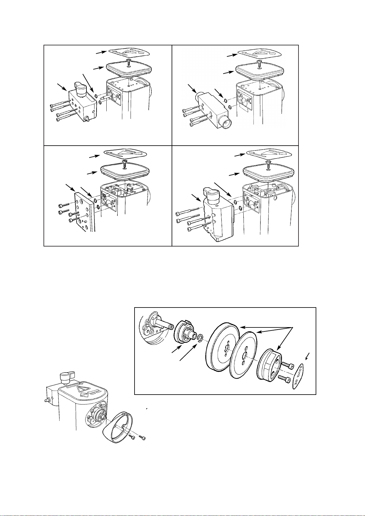
Dismantling the vaporizer
Connector Block
1. Remove the four M4 cap-head screws
(1) and the connector block (2).
2. Remove the O-seals (3) (connector
block to valve block).
3. Remove the top label (4) and lid (5)
(M6 countersunk screw).
Dial Assembly
4. Remove the dial label (6), and
discard.
5. Remove the two M3 cap head screws
and dial assembly (7).
6. Remove the circlip (8) from the shaft,
and remove the dial drive (9).
7. Remove the dial bezel (10) - two M3
cap-head screws.
23
2
10
1
4
5
3
1
1
Selectatec
North American Drager
Drager
2
2
4
4
5
5
3
3
Cagemount
Dial Assembly
Connector Blocks
1
3
2
4
5
6
7
8
9

Interlock - Selectatec
8. Remove the interlock shaft (11) and spring
(12).
Note - on Cagemount, Drager and North
American Drager models a dial return shaft
(plus spring) is fitted.
Interlock - Drager and North American
Drager
9. Remove the interlock system components
(13).
Dial Stops and Closing Mechanism
Shaft - All models
10. Remove the dial ‘zero’ lock screw (14)
11. Remove the closing mechanism shaft (15).
12. Remove the dial ‘max’ stop (16).
24
SERVICE PROCEDURES
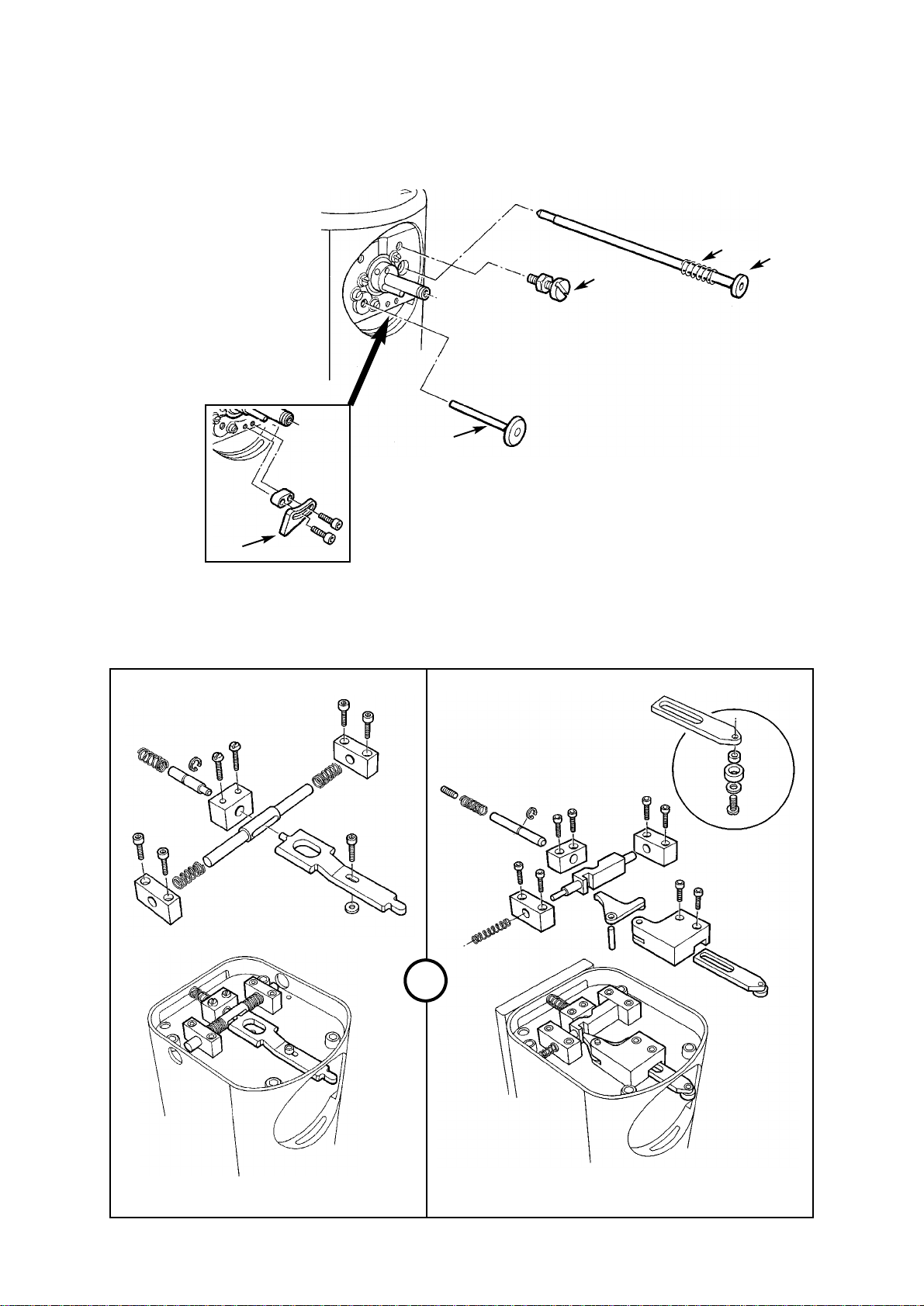
Drager Interlock
15
14
12
11
25
16
North American
Drager Interlock
13
Selectatec Interlock Shaft,
Dial Stops and Closing
Mechanism Shaft
 Loading...