

Prima SP Anaesthetic
Machine Range
User Manual
Quality and Assurance in Anaesthesia

THE IMPORTANCE OF PATIENT MONITORING
WARNING
Anaesthetic systems have the capability
to deliver mixtures of gases and vapours
to the patient which could cause injury or
death unless controlled by a qualified
anaesthetist.
There can be considerable variation in
the effect of anaesthetic drugs on individual patients so that the setting and
observation of control levels on the
anaesthesia systems does not in itself
ensure total patient safety.
Anaesthesia system monitors and patient
monitors are very desirable aids for the
anaesthetist but are not true clinical monitors as the condition of the patient is
also dependent on his respiration and the
functioning of his cardio-vascular system.
IT IS ESSENTIAL THAT THESE ELEMENTS
ARE MONITORED FREQUENTLY AND
REGULARLY AND THAT ANY OBSERVATIONS ARE GIVEN PRECEDENCE OVER
MACHINE CONTROL PARAMETERS IN
JUDGING THE STATE OF A CLINICAL
PROCEDURE.

IMPORTANT
Servicing and Repairs
In order to ensure the full operational life of
this anaesthetic machine, servicing by a
Penlon-trained engineer should be
undertaken periodically.
The machine must be serviced to the
schedule detailed in section 8.
Details of these operations are given in this
Service Manual, available only for Penlon
trained engineers.
For any enquiry regarding the servicing or
repair of this machine, contact the nearest
accredited Penlon agent:
or communicate directly with:
Service Department
Penlon Limited
Radley Road
Abingdon
OX14 3PH
UK
Tel: +44 (0) 1235 547063
Fax: +44 (0) 1235 547062
E-mail: service@penlon.co.uk
Always give as much of the following
information as possible:
1. Type of equipment
2. Product name
3. Serial number
4. Approximate date of purchase
5. Apparent fault
(i)

FOREWORD
This manual has been produced to provide
authorised personnel with information on the
function, routine performance, maintenance
checks and repair procedures applicable to
the Prima SP anaesthetic machine range.
Information contained in this manual is
correct at the date of publication.
The policy of Penlon Limited is one of
continued improvement to its products.
Because of this policy, Penlon Limited
reserves the right to make any changes
which may affect instructions in this manual,
without giving prior notice.
Personnel must make themselves familiar
with the contents of this manual and the
machine’s function before using the
apparatus.
Copyright © Penlon Limited, 2002.
All rights reserved.
(ii)

CONTENTS
Page No.
USER RESPONSIBILITY 01
1. WARNINGS AND CAUTIONS 02
2. PURPOSE 05
3. DESCRIPTION 06
3.1 Framework and General Construction 06
3.2 Gas Circuit NON-AHD MACHINES 07
3.3 Gas Circuit Schematic 07
3.4 Gas Supply Safety Devices 10
3.5 Mechanical AHD 11
3.6 Pressure Gauges 12
3.7 Flowmeters and Controls 13
3.8 Vaporizers 14
3.9 Common Gas Outlet (CGO) Block 15
3.10 Electrical Power Supply 16
3.11 Third/Fourth Gas Options 17
3.12 Auxiliary Gas Outlets 17
3.13 Oxygen Monitor 18
3.14 A100 Absorber 23
3.15 Prima SP Anaesthetic System - MRI Compatibility 23
4. SPECIFICATION 24
4.1 Physical Dimensions 24
4.2 Gas Supplies 25
4.3 Flowmeters 25
4.4 Gas Pressures 26
4.5 Auxiliary Gas Outlets 27
4.6 Oxygen Failure Warning Devices 27
4.7 Oxygen Flush 27
4.8 Mechanical AHD Systems 27
4.9 Environmental 28
4.10 Third and Fourth Gas Options 28
4.11 Electrical Supply 28
4.12 Oxygen Monitor 29
5. PRE-USE CHECKS 31
5.1 Pre-use Check List 31
5.2 Pre-use Checks (Non-AHD Machines) 33
5.3 Pre-use Checks (Machines with Mechanical AHD) 35
5.4 Leak Rate Check 37
5.5 Electrical Supply 37
5.6 Patient Breathing System 38
5.7 Oxygen Flush 42
5.8 Anaesthetic Gas Scavenge System (AGSS) 42
5.9 Alarm System Testing 43
5.10 Vaporizers 44
5.11 Ventilator 44
5.12 Oxygen Monitor 45
(iii)

CONTENTS
6. FUNCTION TEST 49
6.1 Introduction 49
6.2 Machine Frame 50
6.3 Electrical Safety Tests 50
6.4 Pipeline Gas Supply and Non-Return Valve 51
6.5 Cylinder Gas Supply and Pressure Reducing Valves 52
6.6 Flowmeter Unit 54
6.7 Gas Safety Devices 56
6.8 Vaporizers and Back Bar Manifold Assembly 57
6.9 Reduced Pressure Gas Circuit Leakage 58
6.10 Emergency Oxygen Flush Control Test 58
7. FAULT FINDING 59
7.1 Introduction 59
7.2 Fault Diagnosis Table 60
8. SERVICE SCHEDULE 69
8.1 Service Schedule 69
8.2 Six Month Service Checks 69
8.3 Twelve Month Service Checks 72
8.4 Twenty-four Month Service Checks 75
8.5 Seventy-two Month Service Checks 78
9. SERVICING PROCEDURES 82
9.1 Servicing 82
9.2 Ancillary Equipment 82
9.3 Cleaning and Sterilisation 84
9.4 Gas System Components 85
9.5 Internal Gas Pipework 85
9.7 Front Cover - Remove and Refit 88
9.7 Flowmeter Cover 89
9.8 Gear Linkage - Reset 90
9.9 Control Valve Capsule Removal/Replacement 92
9.10 Oxygen Reservoir - Removal/Replacement 93
9.11 Secondary Regulators 94
9.12 Gas Block - Remove and Refit 95
9.13 Selectatec Compatible Manifold Block 96
9.14 Gas Delivery Switch 97
9.15 Air/N2O Interlock Switch 98
9.16 Oxygen Failure Visual Indicator 99
9.17 CGO - Clippard Valve Replacement 100
9.18 Flowmeter Tubes - Removal 101
9.19 Flowmeter Assembly - Removal 102
9.20 Flowmeter Lighting - Removal 103
9.21 Oxygen Monitor - Battery Replacement 104
9.22 Oxygen Monitor Sensor 105
9.23 A100 Circle System Absorber 106
10. SPARE PARTS LIST 107
11. APPENDIX 130
Care of Back-up Battery 130
Product Classification and Labelling Terminology 131
Wiring Diagram - Lighting 132
Wiring Diagram - General 133
(iv)

USER RESPONSIBILITY
This anaesthetic machine has been built to
conform with the specification and operating
procedures stated in this manual and/or
accompanying labels and notices when
checked, assembled, operated, maintained
and serviced in accordance with these
instructions.
To ensure the safety of this device it must be
checked and serviced to at least the
minimum standards laid out in this manual.
A defective, or suspected defective, product
must not under any circumstances be used.
The user must accept responsibility for any
malfunction which results from noncompliance with the servicing requirements
detailed in this manual.
Additionally, the user must accept
responsibility for any malfunction which may
result from misuse of any kind or noncompliance with other requirements detailed
in this manual.
Statements in this manual preceded by the
following words are of special significance:
WARNING means there is a
possibility of injury to
yourself or others.
CAUTION means there is a possibility
of damage to the apparatus
or other property.
NOTE indicates points of
particular interest for more
efficient and convenient
operation.
Always take particular notice of the
warnings, cautions and notes provided
throughout this manual.
Worn, broken, distorted, contaminated or
missing components must be replaced
immediately. Should such a repair become
necessary it is recommended that a request
for service advice be made to the nearest
Penlon accredited agent.
This device and any of its constituent parts
must be repaired only in accordance with
written instructions issued by Penlon
Limited and must not be altered or modified
in any way without the written approval of
Penlon Limited. The user of this equipment
shall have the sole responsibility for any
malfunction which results from improper
use, maintenance, repair, damage or
alteration by anyone other than Penlon or its
appointed agents.
USA and Canadian Federal Law restricts the
sale and use of this device to, or on the order
of, a licensed practitioner.
1

1. WARNINGS AND CAUTIONS
The following WARNINGS and
CAUTIONS must be read and
understood before using this
anaesthetic apparatus.
WARNINGS
1. This apparatus is designed for use
only with non flammable
anaesthetic agents. It must not be
used with or in close proximity to
flammable anaesthetic agents, due
to a possible fire or explosion
hazard.
2. Exterior panels must not be
removed by unauthorised
personnel and the apparatus must
not be operated with such panels
missing.
On machines with an electrical
power supply, there is a possible
electric shock hazard.
during test procedures as well as
during use with a patient.
6. Prima SP machines must only be
used with Sigma Delta vaporizers
(or other vaporizers approved by
Penlon Limited) installed by means
of the Cagemount or Selectatec
system.
Free-standing vaporizers may be
accidentally tipped, resulting in
excessive and uncalibrated
volumes of anaesthetic drug
entering the breathing system
Do not install or connect any
vaporizers of any description
between the Common Gas Outlet
(CGO) and the breathing system
unless they are specifically
designed for such use. (If this is
done, the oxygen flush flow will
pass through the vaporizer and
may result in gross overdosage
when the flush valve is operated.)
3. No oil, grease or other flammable
lubricant or sealant must be used
on any part of the machine in close
proximity to medical gas
distribution components.
There is a risk of fire or explosion.
4. When attaching cylinders of
medical gases ensure that the
machine yoke and cylinder faces
are dust free and clean and that the
sealing washer provided is in
position between the cylinder
valve and the yoke.
Tighten the yoke securely before
opening the cylinder valve. Dust
and dirt presents a fire hazard in
the presence of high pressure gas.
Leakage of high pressure gas can
cause serious injury.
5. Anaesthesia apparatus must be
connected to an anaesthetic gas
scavenging system (AGSS) to
dispose of waste gas and prevent
possible health hazards to
operating room staff.
This requirement must be observed
7. The breathing system which
conveys gases from the
anaesthetic machine to the patient
and disposes of expired gases is a
vital part of the anaesthetic delivery
system.
Because breathing systems require
frequent cleaning and disinfection
they are not a permanent part of the
anaesthetic machine and therefore
cannot be directly under the
control of the anaesthetic machine
manufacturer.
However, we strongly recommend
that only breathing systems which
have been approved and
authorised by Penlon for use with
the Prima SP range should be
employed.
This is particularly important when
mechanical ventilation is
employed.
8. When mechanical ventilation is
employed the patient breathing
system must be connected directly
to an over-pressure relief valve to
prevent the possibility of
barotrauma.
2

WARNINGS AND CAUTIONS
9. Always perform a pre-use check of
the machine, including vaporizers,
ventilator, circle absorber and
monitors before clinical use.
Follow the pre-use checklist (see
section 5) as a minimum
requirement.
Many clinical accidents occur
because of a failure to check for
correct function.
10. The machine must not be used if
any of the alarm, monitoring or
protection system devices are not
functioning correctly.
11. The machine must not be fitted with
more than four operator accessible
mains socket outlets. There is a
risk of an excessive leakage
current.
12. The use of antistatic or electrically
conductive breathing hoses is not
recommended when using high
frequency electrical surgery
equipment (e.g. : Diathermy).
Burns may be caused.
14. Before any electrically powered
machine is used clinically for the
first time, check that the hospital
engineering department has
carried out an earth continuity test.
15. Before using any additional
electrical equipment powered by
the auxiliary sockets on the
machine, check that the additional
equipment is correctly wired and is
earthed through its plug.
A missing or defective protective
earth conductor may increase earth
leakage currents to the patient to
values exceeding the allowable
limits, resulting in ventricular
fibrillation, or interference with the
pumping action of the heart.
Take care when moving a fully
loaded machine, particularly when
negotiating ramps.
Check that hoses or power leads
are not trailing on the floor.
CAUTIONS
1. Flowmeter needle valves are
designed to seal with light torque and
may be damaged if tightened
excessively.
Take particular care with the carbon
dioxide flowmeter control (if fitted); do
not force the control knob past either
the fully open or fully closed positions.
2. Open cylinder valves slowly to avoid
damage to pressure reducing valves.
Ensure that cylinder valves are at
least one full turn open when in use.
3. Under no circumstances should
anaesthetic agents be used for
cleaning purposes.
4. After use, always disconnect the
machine from the piped gas supply
and/or close the gas cylinder valves.
5. Mechanical AHD system - The oxygen
flow control is restricted to prevent the
needle valve from fully closing. This
ensures a minimum basal flow of
oxygen.
DO NOT attempt to close the flow to
zero.
Do not overtighten.
6. Compressed gas supplies must be
clean and dry.
16. Additional equipment placed on the
top shelf must be securely
attached.
3

WARNINGS AND CAUTIONS- O2 Monitor
Oxygen Monitor
WARNINGS
1. We recommend calibration of the
oxygen monitor every time the
system is turned on, as a safety
precaution.
2. Do not attempt to open the fuel
cell. The sensor contains a small
quantity of electrolyte, classified as
a harmful irritant which is
potentially hazardous.
3. ALWAYS check the integrity of the
sensor assembly before use. See
section 3.4.
4. Once exhausted, the sensor must
be disposed of according to
hospital, local, state and federal
regulations.
5. The sensor measures oxygen
partial pressure, and its output will
rise and fall due to pressure
change.
An increase in pressure of 10% at
he sensor inlet will produce a 10%
increase in sensor output.
Using the oxygen monitor
6. When the battery voltage has fallen to the minimum safe level, the
oxygen monitor will automatically
shut down to avoid permanent
damage to the battery.
7. If the internal battery is fully discharged, the oxygen monitor will
not function in the event of mains
power failures.
The battery must be recharged
before the oxygen monitor is used
clinically, otherwise back-up time
can not be guaranteed.
See section 3.13.
CAUTIONS
1. Do not sterilise the oxygen sensor or
control unit components.
These components are not
compatible with sterilisation
techniques and damage may result.
2. Do not autoclave or expose the
sensor to high temperatures.
3. If the sensor shows signs of being
affected by condensation, dry the
sensor with soft tissue.
Do not use heat to dry the sensor.
NOTES
1. The O2 SENSOR FAULT alarm
indicates that one of the following
conditions has occurred.
a) Internal electrical fault
b) Software/electronics fault
c) Oxygen sensor fault.
2. The concentration read-out may, in
certain conditions of excess pressure,
show a value above 100%.
To accommodate these conditions it is
possible to set the high alarm value up
to 105% (see section 5).
3. To maintain maximum sensor life,
always remove the unit from the
breathing circuit after use.
4

2. PURPOSE
The Prima anaesthesia workstation range is
intended to provide controlled
concentrations and flows of anaesthesia
gases into a patient breathing system, from
where the anaesthesia ventilator and
breathing circuit will then deliver this fresh
gas mixture to the patient
Use in conjunction with anaesthetic
vaporizers, breathing hoses and patient
connection fittings which comply with the
relevant ISO standard or equivalent.
Depending upon the patient circuit selected,
the machines can be used in open, semiopen, semi-closed or closed circuit
configurations.
The range has been designed to give a wide
choice of configurations and accessories, as
follows:
Machine size
Prima SP101 Induction machine with a
single vaporizer on the backbar manifold,
and up to three gas cylinders.
Anti-hypoxic Device (AHD)
Machines can be specified with a
mechanical AHD system, designed to
minimise the risk of a hypoxic mixture
reaching the patient, see section 3.
Oxygen monitor (optional)
The Oxygen Monitor is intended to continuously measure and display the concentration
of oxygen in breathing gas mixtures used in
anaesthesia, and is intended for adult, paediatric and neonatal patients.
The oxygen monitor is a module within an
anaesthesia machine.
The oxygen monitor is intended for use by
health care providers, i.e. Physicians,
Nurses and Technicians for use with patients
during general anaesthesia.
Prima SP102 Medium width machine with
capacity for two vaporizers on the backbar
manifold, and up to four gas cylinders.
Gas supplies
SP101 Up to three gases
SP102 Up to four gases (oxygen,
nitrous oxide, carbon
dioxide, and air, with pinindex cylinder yokes (see
above), and provision for up
to three pipeline supply
inlets.
Vaporizer mounting systems
Back bar manifold for Selectatec
Compatible, or Cagemount type vaporizers.
5
3. DESCRIPTION
3.1 Framework and General
Construction
Frame
The machine has a cast base, extruded
aluminium uprights, and aluminium panels.
Mobility
Trolley models have four castors, with a
brake on each of the front castors. The
castors are five inches diameter with antistatic rubber.
A footrest is mounted on the front of the
machine.
To aid manoeuverability, two side handles
are provided.
Mounting posts and brackets
A ‘T-slot’ mounting system is built into each
side upright, to allow the use of pole-mount
brackets, V-brackets, and ventilator
mounting brackets.
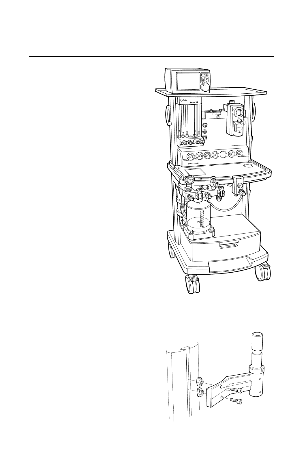
The pole mount upright (see illustration) can
be used to mount a complete AV-series
Ventilator, or bellows unit only.
V brackets can be used to mount a gas
scavenging system, suction units, and
accessories.
Draw units and work surfaces
The machine can be fitted with a base
drawer unit (as illustrated) plus two
additional smaller drawers.
The work surface has has raised edges to
prevent instruments, vials etc. from rolling
off.
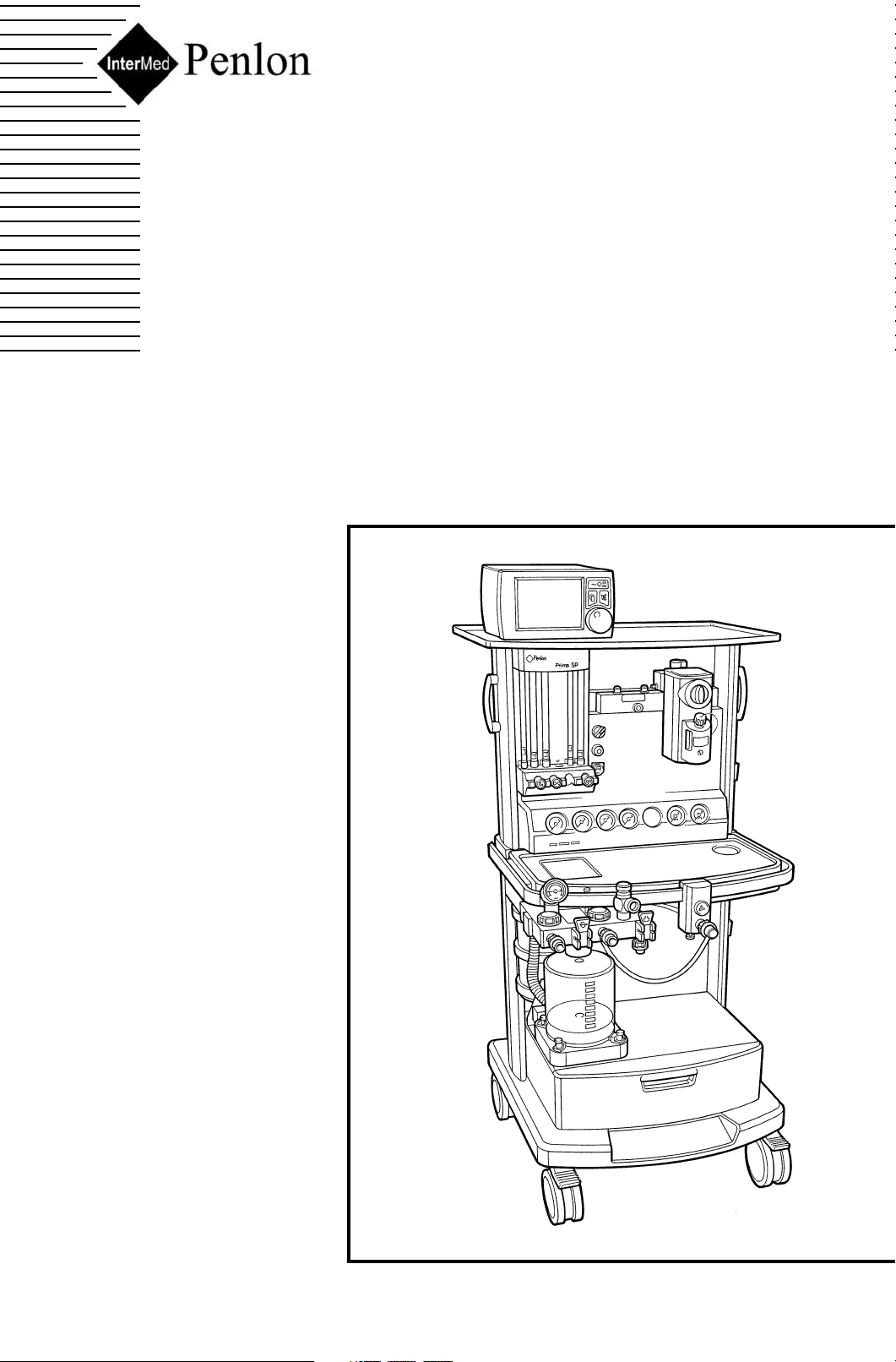
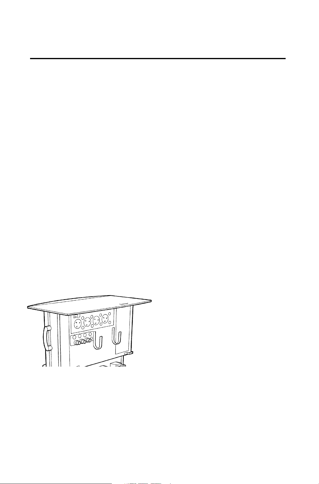
The Prima SP 102 illustrated is equipped
with a standard full-width top shelf unit
suitable for a large monitor, and a pull-out
writing tablet mounted under the work
surface.
Options available include a CPU tray
mounted above the drawer unit.
Prima SP 102 with
standard top shelf
and base drawer unit
Pole mount system
fitted to frame upright
6

DESCRIPTION
3.2 Gas Circuit
Gas Supplies
For each size machine, a variety of cylinder
and pipeline combinations can be added to
the basic specification of oxygen and nitrous
oxide cylinder and pipeline supply.
For example, the Prima SP102 can be supplied with an extra two gas cylinders (choose
from one additional oxygen, one additional
nitrous oxide, one carbon dioxide, one air),
and one extra pipeline supply - Air.
Note a) Kits are available for fitment to
existing machines - see section
9 (Ordering Information).
b) Carbon dioxide is not available
on US specification machines.
Cylinder Yokes
The cylinder yokes are rear mounted and
conform with ISO standards for pin-index
fitting.
To ensure that only cylinders of the
appropriate gas may be installed the yokes
are designed so that the retaining latch
cannot be closed unless the index pins are
fully engaged.
Pipeline Inlets
Machines can be fitted with up to three
pipeline gas inlets mounted on the rear of
the machine.
Pipeline supply hoses are connected by
non-interchangeable, threaded unions.
Filters
To prevent dirt entering the gas system,
cylinder yokes and pipeline inlets are fitted
with filters.
pressure gauge tapping for direct mounting
of a pressure gauge, and a non-return valve
to prevent back flow of gas.
In addition, gas blocks for cylinder supplies
have a diaphragm pressure regulator to
reduce the pressure of the compressed gas
supply, and a pressure relief valve, factory
set to prevent any pressure build up under
the diaphragm should any leakage develop
across the reducing valve seat.
Secondary Pressure Regulator
For oxygen, nitrous oxide, and air, a second
stage regulator reduces the pressure
supplied to the flowmeter controls (see
section 4.4).
The fitment of a secondary regulator for
oxygen and nitrous oxide enhances the
performance of the mechanical AHD system
fitted to some models.
Secondary regulation of the air supply is
utilised to allow connection to high pressure
air pipeline supplies.
Carbon Dioxide Flow Restrictor
On machines with a carbon dioxide supply,
an integral, factory set, flow valve is fitted to
restrict the flow of carbon dioxide to 500
ml/min.
3.3 Gas Circuit Schematics
Gas circuit schematics for:
a) Non-AHD machines
b) Mechanical AHD machines
are shown on the following pages, and both
show a four-gas machine.
All available gas supply options are shown.
Gas Inlet Block
Each individual gas supply, from a cylinder
or pipeline, is routed through a separate gas
block.
Each gas block has an integral high
Note that carbon dioxide is not available for
US specification machines.
7
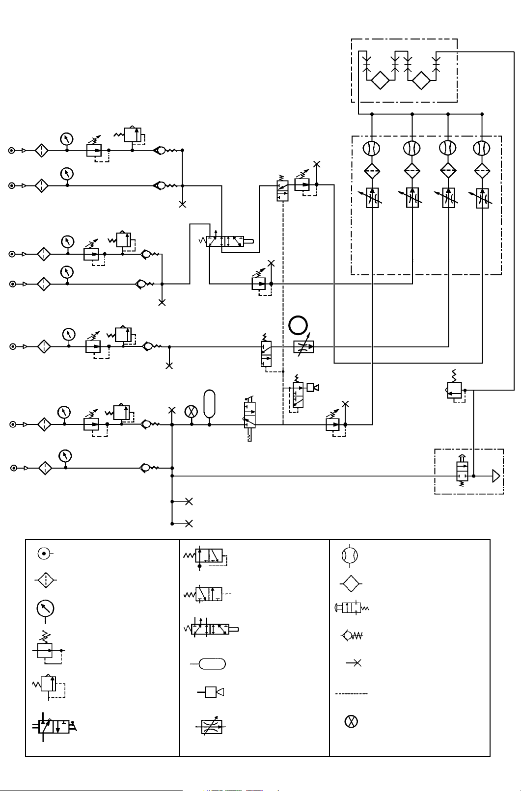
Prima SP Non-AHD Machine
UK specification four-gas machine
Note: US spec. machines are not fitted with CO
Air
N2O
facility
2
CO
O
2
2
Pneumatic pressure
source
Filter
Pressure gauge
Pressure regulator
Pressure relief valve
Pneumatic on/off
switch
Gas cut-off valve
(normally open)
Gas cut-off valve
(normally closed)
Gas cut-off valve
(open/closed)
Reservoir
Audible alarm
Flow control valve
(variable, but note
that valve 1 is not
user-adjustable)
1
Flowmeter
Vaporizer
Oxygen flush valve
Non-return valve
Power take-off point
(or test point)
Gas reference
connection
Visual indicator
8
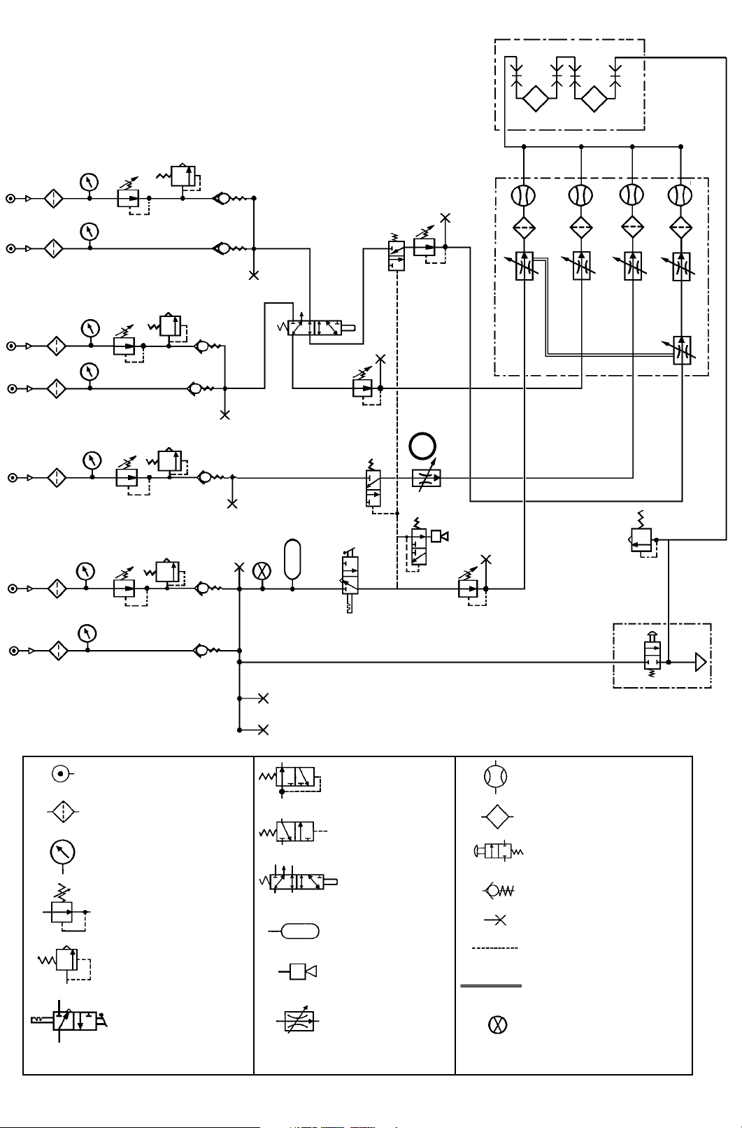
Prima SP Mechanical AHD Machine
UK specification four-gas machine
Note: US spec. machines are not fitted with CO
Air
N2O
facility
2
CO
O
2
1
2
Pneumatic pressure
source
Filter
Pressure gauge
Gas cut-off valve
(normally open)
Gas cut-off valve
(normally closed)
Gas cut-off valve
(open/closed)
Flowmeter
Vaporizer
Oxygen flush valve
Non-return valve
Pressure regulator
Pressure relief valve
Pneumatic on/off
switch
Reservoir
Audible alarm
Flow control valve
(variable, but note
that valve 1 is not
user-adjustable)
9
Power take-off point (or
test point)
Gas reference
connection
Mechanical connection
Visual indicator

DESCRIPTION
3.4 Gas Supply Safety
Devices
3.4.1 Gas Supply Cut-off Device
A gas cut-off device, triggered by low oxygen
supply pressure, cuts the supply of nitrous
oxide, and carbon dioxide (if fitted).
The cut-off operates when the oxygen
pressure falls below 172 kPa (25 psi).
Gas supplies are reinstated only when the
oxygen supply pressure rises above 227
kPa (33 psi).
3.4.2 Oxygen Supply Failure
Warning Whistle
A whistle gives an audible warning when
there is a reduction of oxygen supply
pressure.
Operated solely by the remaining oxygen in
the machine system, the warning whistle is
prolonged by an oxygen reservoir built into
the gas circuit, allowing a minimum warning
whistle of 7 seconds duration.
The whistle will start to sound when the
pressure falls to approximately 172 kPa (25
psi), and will continue to sound until the
pressure falls to approximately 70 kPa (10
psi).
3.4.4 Air/N
(Machines with Air option)
The user can switch
between Air and
Nitrous Oxide (A).
NOTE
a) The machine will
NOT deliver a
mixture of Air and
nitrous oxide.
b) On machines with
Mechanical AHD, the
2/N2O linkage
O
continues to operate.
2O Interlock
B
A
3.4.5 Oxygen Supply Visual
Indicator
The indicator (B) is operated from the
oxygen supply and shows GREEN when the
supply is at working pressure, and RED if
the pressure falls.
3.4.6 CO2 Flow Restriction
The maximum flow of carbon dioxide is
restricted to 500 ml/min by a pre-set flow
control valve.
This valve is not user-adjustable.
Note that carbon dioxide is not available for
US specification machines.
Oxygen consumption of the whistle is
approximately 2 L/min when sounding and
nil at other times.
3.4.3 Fresh Gas Pressure Relief
Valve
A pressure relief valve is mounted between
the vaporizer back bar and the common gas
outlet (CGO) on the inside face of the
machine right hand upright.
It is designed to prevent fresh gas being
delivered to the breathing system at
pressures exceeding 39 kPa (5.4 psi).
This valve also protects machine
components against excessive pressure in
the event of a total blockage of the CGO.
3.4.7 Mechanical AHD
A mechanical link between the oxygen
control valve and a needle valve in the
nitrous oxide flow ensures that the machine
delivers a fresh gas mixture with a minimum
oxygen concentration of 30% ±3%,
irrespective of the flow of nitrous oxide set by
the anaesthetist.
With the nitrous oxide control valve fully
open, the oxygen and nitrous oxide flows are
then both controlled by the oxygen control
valve.
See section 3.5 for a full description
3.4.8 Low Pressure Gas Tubing
Diameter-indexed tubing is used for the low
pressure gas system - see section 4.
10

DESCRIPTION
3.5 Mechanical AHD (Anti
Hypoxic Device)
3.5.1 Introduction
The Mechanical AHD is housed within the
flowmeter module and comprises a gear
linkage between the oxygen control valve
and a needle valve in the nitrous oxide flow.
The system is designed to control the
relative flow rates of oxygen and nitrous
oxide.
A predetermined minimum oxygen
concentration of 30% ±3% in the oxygen /
nitrous oxide mixture is maintained over the
flow range to ensure that a hypoxic mixture
is not supplied from the anaesthetic
machine.
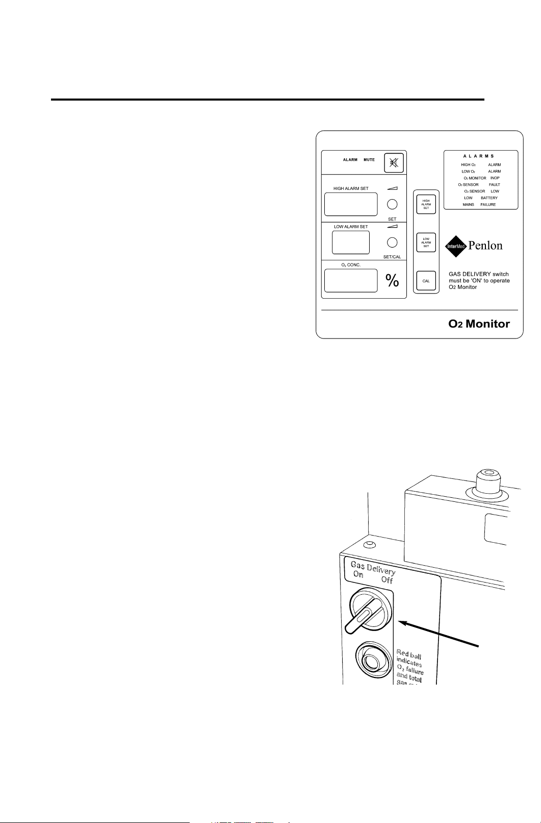
3.5.2 Gas Delivery Switch
The Gas Delivery Switch (A) operates on the
oxygen supply and must be in the ‘On’
position for normal operation of the
anaesthetic machine.
The switch consequently controls the supply
of all gases provided with a gas cut-off
triggered by a predetermined pressure level
within the oxygen supply (see section 3.4.1).
A whistle (oxygen failure warning whistle)
will sound briefly whenever the gas delivery
switch is turned on or off. Note that the
whistle functions normally if the oxygen
supply fails (see section 3.4.2).
The switch also controls the electrical supply
to the optional Flowmeter Lighting unit and
2 Monitor (see section 3.13.2).
O
A
B
NOTE
Machines with an Air supply option are fitted
with an Air/N2O Interlock switch (B).
The machine will NOT deliver a mixture of
Air and nitrous oxide - see section 3.4.4) .
This switch must be in the N
allow a flow of Nitrous Oxide.
The nitrous oxide control knob on the
flowmeter module operates a secondary
needle valve in the nitrous oxide flow. It is
positioned downstream of the primary valve
and therefore is used only to restrict the flow
already set by the primary valve, which itself
has been determined by the position of the
oxygen control knob.
Therefore for any oxygen flow set by the
user, the mixture delivered will still contain a
minimum 30% ±3% oxygen even with the
nitrous oxide control knob fully open. As the
nitrous oxide knob is progressively closed,
the oxygen content of the mixture increases
to 100%.
2O position to
3.5.3 Gear Linkage and Nitrous
Oxide Control Valves
A gear linkage connects the oxygen control
knob on the flowmeter module and a needle
valve in the nitrous oxide flow.
This linkage limits the flow of nitrous oxide
relative to the flow of oxygen set by the user.
Note that this needle valve acts as the
primary nitrous oxide valve, and is actuated
only by movement of the oxygen control.
3.5.4 Oxygen Basal Flow
To allow the system to function correctly, an
oxygen basal flow is continuously supplied
(see section 4.8). This basal flow can only
be turned on and off by using the Gas
Delivery Switch (A).
CAUTION The oxygen control is restricted
to prevent the needle valve from fully
closing. This ensures a minimum oxygen
basal flow.
DO NOT attempt to close the flow to zero.
Do not overtighten the knob.
11

DESCRIPTION
3.6 Pressure Gauges
Pressure gauges (50 mm diameter) are
located on the front panel below the
flowmeter bank.
The gauges for the third and fourth gases (if
fitted) are positioned between oxygen and
nitrous oxide. Unused gauge positions are
blanked out.
All pressure gauges are colour coded and
labelled for the gases whose pressures they
are indicating.
Cylinder contents are marked CYLINDER
and pipeline pressure gauges are marked
PIPELINE.
The gauges are calibrated in kPa x 100.
12
DESCRIPTION
3.7 Flowmeters and
Controls
3.7.1 All models
The flowmeters, mounted behind the
perspex cover on the left hand side of the
machine, are length-indexed to prevent
inadvertent, incorrect installation.
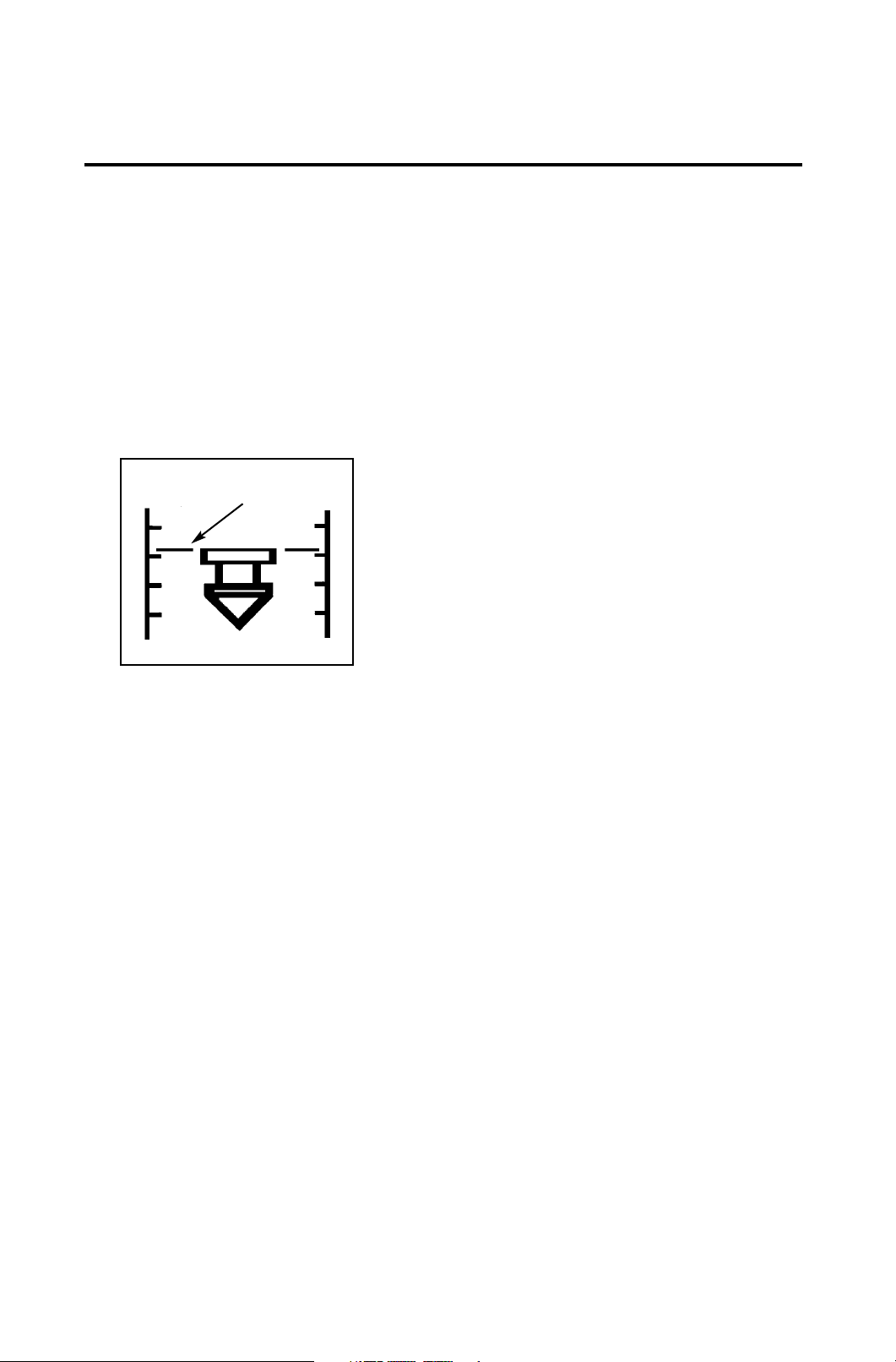
All floats indicate flow rate in line with the
upper surface as shown below.
Read flow at
this level
Each flow control valve is positioned directly
underneath the flow tube assembly to which
it corresponds, and the control knob is
colour-coded for the gas which it controls.
supply of oxygen and must be in the ON
position for normal operation of the
machine.
Flow control of each gas is achieved by a
needle valve comprising a polished stainless
steel needle mounted concentrically in a
common manifold block. To minimise wear
and material pick-up the needle seat is
manufactured from silver. The flow control
knob is turned counter-clockwise to increase
the gas flow.
CAUTION
Needle valves are designed to seal with light
torque and may be damaged if tightened
excessively.
DO NOT USE EXCESSIVE FORCE.
3.7.2 Optional Dual Cascade
Flow Tubes
The flow of gas through dual cascade
system flow tubes always flows through the
low-flow tube first. The high-flow tube will not
show any flow until more than 1 L/min is set.
At flows above 1 L/min, the high-flow tube
reading indicates the rate of flow for that gas.
The oxygen flow control knob is made
physically distinguishable from the other flow
controls for identification by touch in
accordance with ISO standards.
When fitted, air and carbon dioxide
flowmeters are always installed in the inner
positions on the flowmeter assembly. These
positions are blanked out if air or carbon
dioxide are not specified for the machine.
NOTE
Machines with an Air supply option are fitted
with an Air/N
machine will NOT deliver a mixture of Air
and nitrous oxide - see section 3.4.4) .
This switch must be in the N
allow a flow of Nitrous Oxide.
The gas delivery switch, positioned to the
right of the flowmeter bank, controls the
2O Interlock switch (The
2O position to
3.7.3 Carbon Dioxide Flow
Restriction
The maximum flow of carbon dioxide (if
fitted) is restricted to 500 ml/min.
13

DESCRIPTION
3.8 Vaporizers
CAUTION
Read the instruction manual supplied with
the vaporizer before clinical use.
3.8.1 Vaporizer Mounting
Systems
Vaporizers for the administration of volatile
anaesthetic agents can be fitted to
customer’s requirements as follows:
(a) Up to two Penlon Sigma Delta
Selectatec compatible vaporizers
(interlock or non-interlock), mounted
on a Selectatec compatible backbar.
(b) One or two Penlon Sigma Delta
Cagemount vaporizers mounted on a
Modura rail (check that relevant
national standards for your country
allow fitment of more than one
cagemount type vaporizer).
WARNING
Vaporizers must always be securely
mounted, and never used free-standing.
Unmounted vaporizers may be
accidentally tipped resulting in
uncalibrated and excessive volumes of
liquid anaesthetic drug entering the
breathing system.
Vaporizers of any description must not be
installed or connected between the Common
Gas Outlet (CGO) and the Breathing
System, unless they are specifically
designed for such use. (If this is done, the
oxygen flush flow will pass through the
vaporizer, and severe overdosage may
result).
3.8.2 Selectatec Compatible
Vaporizers
Selectatec compatible vaporizers, e.g. the
Sigma Delta with the Selectatec
compatibility block, may be mounted on a
universal back bar manifold built onto the
Prima range as an option.
Single and two-station manifolds are
available, with each station fitted with two
valve capsule assemblies for vaporizer
connector block attachment.
When a vaporizer is installed on a station the
valves on that station open automatically to
allow gas flow into and out of the vaporizer.
Removal of the vaporizer from the station
closes the valves on that station.
Selectatec Compatible vaporizer interlock
systems are described in the literature
supplied with the vaporizer.
3.8.3 Cagemount Vaporizer
Vaporizers fitted with cagemount tapers
have the male taper (inlet port) on the left,
and the female taper on the right (viewing
the front of the vaporizer).
It is recommended that detachable
cagemount connectors are retained with a
safety clip (catalogue number 52275) to
prevent inadvertent disconnection.
14

DESCRIPTION
3.9 Common Gas Outlet
(CGO) Block
The CGO block is mounted on the rail on the
front of the machine, and can be moved
along the rail.
Slacken the securing screw under the block
and carefully slide the block along the rail to
the required position.
Tighten the screw to hold the block in place.
The fresh gas outlet is located on the front
face of the block, with 22 mm male taper and
concentric 15 mm female taper. The male
taper incorporates the Penlon Safelock
system designed to prevent accidental
disconnection of the breathing system.
A high mounting position for the CGO is
available as an option for induction
machines.
Oxygen Flush
An emergency oxygen flush valve button is
mounted on the top front of the CGO block
and is marked ‘O
Depressing the button provides a delivery of
between 35-75 litres/min of oxygen into the
common gas outlet.
Releasing the button allows the springloaded valve to return to its normal position.
2 FLUSH’.
15
DESCRIPTION
3.10 Electrical Power
Supply (if specified)
3.10.4 AV900 or AV800 Ventilator
(if fitted) Power Supply
3.10.1 Mains Power Supply
Power is fed to the machine via the mains
lead, to power an auxiliary output panel, and
optional flowmeter bank light.
NOTE
a) It is the user’s responsibility to ensure
that the total sum of leakage currents from
additional equipment plugged into the
auxiliary sockets plus the leakage current
from the machine does not exceed the
values specified in any relevant national
standards that may apply in the country
where the machine is in use.
b) Each socket is protected with a 5 Amp
fuse.
3.10.2 Auxiliary Power Supply
Sockets (if fitted)
An optional mains electricity auxiliary panel
with three or four sockets can be specified,
and fitted to the rear of the machine.
A
The mains lead for an AV-series ventilator
can be plugged into one of the auxiliary
power sockets on the rear of the machine.
Should the electrical power supply to the
ventilator fail, the ventilator has a battery
back up system to power the ventilator for 60
minutes, if the battery has been maintained
in a fully charged condition.
Reference must be made to the separate
user instruction manual supplied with the
ventilator
Charging of the back-up battery takes place
automatically when the ventilator mains lead
is connected to a ‘live’ mains supply.
The OFF indicator on the ventilator front
control panel will show a yellow light during
charging.
NOTE
The stated battery back-up period will only
be available if the battery is kept fully
charged. After the back-up power supply has
been run down, the ventilator will not
function until the battery is in a fully charged
state.
A fourteen hours recharge will be necessary
to bring the battery to full charge.
The supply to the sockets is controlled by an
ON/OFF switch (A).
3.10.3 Flowbank Lighting
(optional)
The lighting system is controlled by the
main ON/OFF switch (A).
3.10.5 Monitor and Other
Accessories (if fitted)
The mains lead (or adaptor) for a monitor
system or other accessories requiring an
electrical supply can be plugged into one of
the auxiliary sockets on the rear of the
machine.
See 3.13.17.
16
DESCRIPTION
3.11 Third/Fourth Gas
Options
3.11.1 Air
When air is requested as the third/fourth gas,
the machine specification is modified as stated
in 4.10.1.
NOTE
Machines with an Air supply option are fitted
with an Air/N
will NOT deliver a mixture of Air and nitrous
oxide - see section 3.4.4).
This switch must be in the N2O position to
allow a flow of Nitrous Oxide.
3.11.2 Carbon Dioxide
When carbon dioxide is requested as the
third/fourth gas, the machine specification is
modified as stated in 4.10.2.
2O Interlock switch (The machine
Gas supply cut-off devices operate on carbon
dioxide in all machines.
An integral, factory-set flow valve is fitted to
restrict the flow of carbon dioxide to 500
ml/min.
Note that carbon dioxide is not available on US
specification machines.
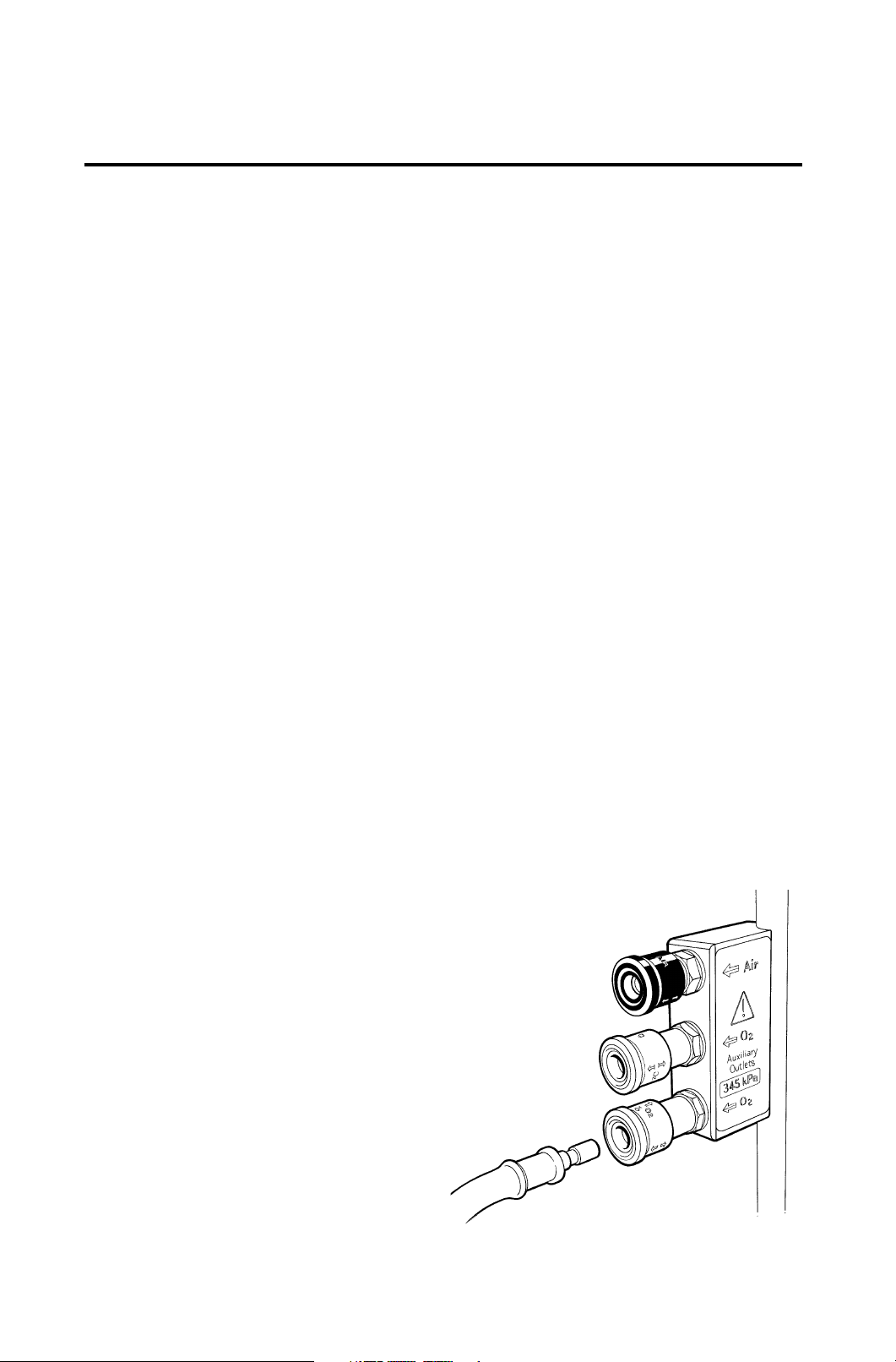
3.12 Auxiliary Gas Outlets
Oxygen
Auxiliary oxygen outlets are mounted on the
right hand side frame upright.
Air
On machines with an air cylinder/pipeline
supply, an auxiliary air outlet is fitted above the
oxygen outlets.
17
DESCRIPTION - O2 Monitor
3.13 Oxygen Monitor (Optional)
The oxygen monitor continuously measures and
indicates the concentration of oxygen in the breathing
system, and triggers an alarm when the concentration
varies from the set levels.
CAUTION
If your machine is fitted with an AV900 Ventilator with
a built-in Oxygen Monitor, please refer to the AV900
user manual for instructions on setting up and
operation.
3.13.1 System Description
The Oxygen Monitor uses a fast-responding, oxygenspecific, self powered sensor that achieves 90% of
final value in less than 10 seconds.
Sensor life:
approximately 1 500 000 O
20oC
(minimum one year in most normal applications).
2 percent hours at
An external probe is supplied with a 2 m (6 ft)
extendable cable and diverter fitting for a standard 15
mm Tee adaptor. The probe has a safety lock.
The system has user-adjustable high-level and lowlevel alarms with visual and audible indication of
alarm conditions.
Easy-to-read, seven segment LED display for highset, low-set, and oxygen concentration readings.
The monitor is controlled by the machine gas system
master On/Off switch (A).
A back-up battery provides a minimum of 60 minutes
operation in the event of mains failure.
The battery is charged when the machine is
connected to the mains supply.
3.13.2 System On/Off Switch
The switch controls gas delivery from the anaesthetic
machine, and electrical power to the oxygen monitor.
The switch must be in the On position to use the
oxygen monitor and anaesthetic machine.
A
When switched to On, the monitor will always default
to previous settings.
18
DESCRIPTION - O2 Monitor
5
3
2
10
9
1
6
7
8
4
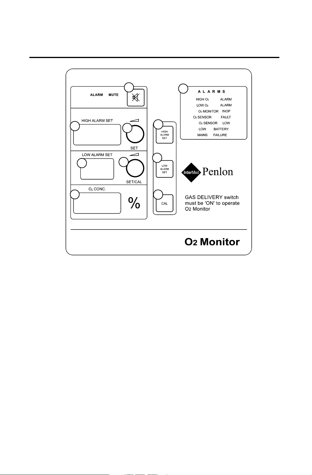
Oxygen monitor control panel
1. O2 Concentration display 6. High set key
2. Low alarm set display 7. Low set key
3. High alarm set display 8. Calibrate key
4. Alarm LEDs 9. Low alarm set / Calibration control
5. Alarm mute key 10. High alarm set control
3.13.3 Displays
Oxygen Percentage Readout
The display provides direct readout of oxygen concentrations in the range of 0-100%.
If the oxygen concentration exceeds 100%, the display will flash.
Low Alarm Set Readout
The indicated value represents the oxygen percentage at which the low alarm will be activated.
The low alarm set value is limited within 18-99%.
To set the low oxygen concentration alarm, see section 3.3.2.
High Alarm Set Readout
The indicated value represents the oxygen percentage at which the high alarm will be activated.
The high alarm set value is limited within 19-105% (Note that in certain conditions of excess pressure,
the readout may show a value above 100%.)
To set the high oxygen concentration alarm, see section 3.3.1.
19

DESCRIPTION - O2 Monitor
3.13.4 Alarm Conditions
HIGH O2 ALARM
The high O
oxygen concentration is 1% above the
setting.
In this alarm condition, a red HIGH O
ALARM LED will flash at a 0.5 second rate,
accompanied by a high priority sound.
To cancel this alarm, the high alarm setting
must be equal to, or above the oxygen
concentration.
LOW O
The low alarm is triggered when the oxygen
concentration is 1% below the setting.
In this alarm condition, a red LOW O
ALARM LED will flash at a 0.5 second rate,
accompanied by a high priority sound.
To cancel this alarm, the low alarm setting
must be equal to, or below the oxygen
concentration.
2 MONITOR INOP (inoperative)
O
This alarm indicates when the oxygen
monitor is in malfunction condition.
It could be triggered by electronic
components failure or software malfunction.
In this alarm condition, a red O
ALARM LED will flash at a 0.5 second rate,
accompanied by a high priority sound.
If this mode occurs you can reset the system
by pressing the ALARM MUTE and LOW
ALARM SET buttons simultaneously for 3
seconds.
2 alarm is triggered when the
2 ALARM
2 MONITOR
will fall very quickly to zero within two to
three weeks of normal usage.
See section 5 for sensor replacement.
NOTE
always remove from breathing circuit after use.
2
LOW BATTERY
To maintain maximum sensor life,
The low battery alarm indicates that the
battery is disconnected or the battery
voltage has dropped below acceptable
limits.
If the monitor is in use under battery power,
and the battery voltage is less than 11.5
volts, a low priority alarm is triggered, to
indicate that the battery has less than 20
2
minutes life left.
If the battery voltage falls to less than 10.8
volts a flashing medium priority alarm is
triggered to indicate there is less than 5
minutes power left in the battery.
To cancel this alarm, mains power must be
On.
NOTE
Penlon Service Centre, or Penlon Customer
Service Department in the UK.
At the end of the final 5 minute warning
period, the oxygen monitor will shut down, to
prevent damage to the battery.
If this condition persists, contact your
MAINS FAILURE
This alarm indicates mains power failure or
cut-off. The yellow MAINS FAILURE LED will
illuminate, and a low priority sound will be
triggered.
2 SENSOR FAULT
O
The alarm is triggered
a) when either the oxygen sensor is
disconnected or approaching the end of its
life.
b) if the the oxygen concentration exceeds
110%.
In the alarm condition, a red O
2 SENSOR
ALARM LED will flash at a 0.5 second rate,
accompanied by a high priority sound.
To cancel this alarm, check the sensor
connection or replace the sensor.
2 SENSOR LOW
O
This alarm indicates the sensor has
approached the end of its life.
The yellow O
2 SENSOR LOW LED will light
up, and a low priority sound will be triggered.
The sensor must be replaced as the output
3.13.5 Alarm Mute
In an alarm condition, pressing the ALARM
MUTE button will deactivate the alarm
sounder but the alarm LED will continue to
flash. The yellow MUTE ALARM LED will
illuminate, accompanied with a SINGLE
‘beep’ sound.
The alarm mute can not be operated:
a) until the mute time is over, or the alarm
condition has been rectified.
b) when the oxygen concentration drops
below 18%.
In high priority and medium alarm conditions
the alarm mute deactivates the sounder for
30 seconds and 120 seconds respectively.
20

DESCRIPTION - O2 Monitor
3.13.6 The MOX-3 Oxygen Sensor
The MOX-3 oxygen sensor offers quick
response, linear output over the entire 0-100%
oxygen range, and long service life.
The MOX-3 is a self-powered galvanic cell that
generates current, and the current is
proportional to the rate of oxygen consumption.
The cell has a highly stable output over its
operating life. Significant output loss is only
shown at the very end of its life.
Typical sensor drift rates are less than 1% per
month when the sensor is exposed to gas in
typical applications.
Sensor lifetime is governed by the mass of lead
available to react with the oxygen and its rate of
consumption. High oxygen partial pressure and
high temperature will increase the sensor
output current, thus shortening the operation
life.
Nevertheless, average sensor life will still
exceed one year.
At the point where all lead has been consumed,
the output will fall very quickly to zero over a
period of two to three weeks.
NOTE
To maintain maximum sensor life, always
remove from breathing circuit after use.
Typical Sensor Installation on
Machine CGO
The sensor assembly consists of an
external probe and 2 m (6 ft) cable and
diverter on a standard 15 mm Tee
adaptor.
On machines with an A100 Absorber,
the probe can also be mounted on the
dome of the inspiratory valve (see section 5).
21

DESCRIPTION - O2 Monitor
3.13.7 Power Supply
Mains Power Supply
Power is fed to the machine via the mains lead to a switching mode power
supply, and the oxygen monitor will be powered up by 14.2 v.
The monitor is controlled by the machine gas system master On/Off switch
(see 3.13.2).
Back-up Battery
Should the electrical power supply to the machine fail, the emergency battery
supply for the unit comes into action automatically.
This is indicated by the illuminated yellow ‘MAINS FAILURE’ LED alarm,
accompanied with a ‘beep’ sound.
The battery is maintained in a fully charged state during normal use (i.e. the
machine connected to the mains power supply).
A fully charged battery will power the unit for a minimum of 60 minutes.
Low Priority Battery Low Alarm
When the battery is discharged, and the mains power supply is not restored,
the ‘BATTERY LOW’ LED alarm will illuminate, accompanied with a low priority alarm sound.
Medium Priority Battery Low Alarm
When the battery is further discharged, and the mains power supply is not
restored, the ‘BATTERY LOW’ LED will flash at a two second rate and a
medium priority audible warning will be given when the minimum safe level of
voltage is reached.
Low Battery Shut Down
WARNING
When the battery voltage has fallen to the minimum safe level, the oxygen monitor will automatically shut down to avoid permanent damage
to the battery.
Recharging the Battery
Charging of the back-up battery takes place automatically when the mains
power supply is on, irrespective of the position of the machine gas system
On/Off switch position.
NOTE
The stated battery back-up period will only be available if the battery is kept
fully charged. After the back-up power supply has been run down, the oxygen monitor will not function until the battery is in a fully charged state. An
eight hours recharge will be necessary to bring the battery to full charge.
22

DESCRIPTION
3.14 A100 Absorber
In-board Mounting
The canister and valve block assemblies are
mounted under the work surface and can be
detached separately for cleaning (see section 7).
3.15 Prima SP Anaesthetic
System - MRI Compatibility
The following Prima SP system components are
MRI compatible:
Prima SP basic* machine
*A 'basic' machine includes any variant of
Back Bar
Flowmeter Bank
Drawers
Monitor Shelves
Additional Gases
A100 Absorber (In-board and pole-mounted)
Nuffield 200 Ventilator
Delta Vaporizer
The following components are currently not
MRI compatible:
Oxygen Monitor
Flowmeter lighting
Electrical power outlets
AV-series ventilator
NOTE
a) MRI Compatible Plastic Laryngoscopes -
see section 3.9 in the Price List.
b) The IDP Pressure Failure Alarm is MRI
compatible when used with appropriate batteries - see section 1.5.3 in the Price List.
23

4. SPECIFICATION
4.1 Physical Dimensions
Overall size: Height x Depth x Width (mm)
SP 101 1475 x 620 x 450
SP 102 1475 x 620 x 570
Work surface height: 890 mm
Work surface size: 690/570/450 x 370 mm
Loading: 30 kg (66 lb) - evenly distributed.
Writing tablet: 300 x 220 mm
Loading: 10 kg (66 lb) - evenly distributed.
Top shelf: 690/570/450 x 370 mm
Loading: 30 kg (66 lb) - evenly distributed.
Mid shelf: 690/570/450 x 370 mm
Loading: 25 kg (55 lb) - evenly distributed
Drawers: 150 x 325 x 500 mm.
Loading: 10 kg (22 lb) evenly distributed
Castors: Front pair braked
Absorber posts: Swivels on a 254 mm radius around the left
hand side frame upright:
Height adjustment 300 to 760 mm
Loading 30 kg (66 lb)
Ventilator bellows post Bushed to accept 25.4 mm (1 inch) or 22
mm (7/8 inch) poles.
Loading 30 kg (66 lb)
Gas scavenging fixing Dovetail clip on frame upright
Loading 30 kg (66 lb)
Common gas outlet: 22 mm male taper with coaxial 15 mm
female taper connections Safelock fitting
Weight:
SP 101 70 kg (154 lb)
SP 102 75 kg (165 lb)
24

SPECIFICATION
4.2 Gas Supplies
Cylinders: Oxygen, nitrous oxide, air, and carbon dioxide
cylinder fittings can be specified to the maximum
numbers given below.
All cylinder yokes are pin-indexed
SP 101 Maximum of three
SP 102 Maximum of four
Pipeline:
SP 101/102 Maximum of three (oxygen, nitrous oxide, air).
All to relevant national standards.
Medical gas colour codes:
Oxygen White* or Green
Nitrous Oxide Blue
Medical Air Black/White* or Yellow
Carbon Dioxide Grey
*To comply with relevant national standards.
Internal pipework is diameter indexed for each gas
Oxygen: 8 mm Carbon Dioxide: 4 mm
Nitrous Oxide 6 mm Air 5 mm
Mixed gas 10 mm
4.3 Flowmeters
Flow ranges:
Single flow tubes
Oxygen: 0 - 10 L/min
Nitrous Oxide: 0 - 10 L/min
Air 0 - 10 L/min
Carbon Dioxide 0 - 700 ml/min (flow limited to 500 ml/min)
Cascade flow tubes
Oxygen /Air /Nitrous Oxide (1) 0 - 1000 ml/min
(2) 0 - 10 L/min
25

SPECIFICATION
Flowmeter Accuracy
The accuracy of the flowmeter tubes is ± 2.5% of full scale reading
Flowmeter construction and dimensions
Tubes and floats are matched, and must not be interchanged.
Flowmeter tubes have antistatic coatings.
Tubes are length indexed:
Oxygen 260 mm (10.24 inch)
Nitrous oxide 250 mm (9.84 inch)
Other gases 240 mm (9.45 inch) (see 3.12)
Scale length 152 mm (6 in) minimum
(all flow tubes except carbon dioxide)
4.4 Gas Pressures
USA/ UK
Canada/
Japan
Pipeline supplies 340 kPa 400 kPa
(50 psi) (60 psi)
Cylinder supplies 310 kPa 380 kPa
(45 psi) (55 psi)
Supply pressure variation ±10% ± 10%
Reduced pressure from regulator 310 kPa
(at 5 L/min flow) (45 psi +2 psi / -5 psi) (55 psi +2 psi / -5 psi)
Regulator diaphragm 2800 kPa 2800 kPa
bursting pressure (410 psi) (410 psi)
Reduced pressure system 510 kPa 610 kPa
safety valve (75 psi) (90 psi)
Safety valve 39 kPa ±10% 39 kPa ±10%
(to protect flowmeter, (5.4 psi) ±10% 5.4 psi ±10%
vaporizer etc.)
Reduced pressure from secondary regulators(at 5 L/min flow)
Machines built from March 2002 onwards
Oxygen and Nitrous Oxide 152 - 241 kPa (22 - 35 psi)
Air 241 - 276 kPa (35 - 41 psi)
Machines built before March 2002
All gases 207 - 283 kPa (30 - 41 psi)
+15 kPa / -35 kPa 370 kPa +15 kPa / -35 kPa
26

SPECIFICATION
4.5 Auxiliary Gas Outlets
Oxygen
Two self sealing connections on side frame upright
Oxygen supply at pipeline pressure 340 kPa (50 psi)
Total flow rate: not less than 100 L/min to free air
80 L/min against 243 kPa (36 psi) resistance
70 L/min against 270 kPa (40 psi) resistance
50 L/min against 297 kPa (44 psi) resistance
Air
One self sealing connection on side frame upright.
4.6 Oxygen Failure Warning Devices
1. Gas system whistle
2. Visual indicator, direct pressure operated
4.7 Oxygen Flush
Button on CGO block
The system supplies 35 - 75 L/min when fully depressed.
4.8 Mechanical AHD System
Minimum oxygen concentration 30% ±3% of total O2 + N2O flow
Oxygen basal flow
All models - up to March 2002
Oxygen basal flow 100-200 ml/min
Cascade flowmeter models - March 2002 onwards
Oxygen basal flow 50-75 ml/min
Single flowmeter models - March 2002 onwards
Oxygen basal flow 100-200 ml/min
Reduced pressure from secondary regulators See section 4.4
27

SPECIFICATION
4.9 Environmental
Operating Conditions
Temperature
Storage and transport:
Basic machine -5 to 60oC (23 to 140oF)
Oxygen monitor option -5 to 50oC (23 to 122oF)
Operating ambient +10 to 38oC (50 to 100oF)
Atmospheric pressure range 70 kPa to 106 kPa
Altitude 2438 m (8000 ft) maximum
Humidity 10 - 95% R.H. non-condensing.
MRI Compatibility See section 3.15
Cleaning Wipe external surfaces with dry or damp cloth.
Use mild soap, or disinfectant solution if necessary.
4.10 Third and Fourth Gas Options
4.10.1 Air
Air flowmeter range: 0 - 10 L/min.
Cascade low flow tube: 0 - 1000 ml/min
Cylinder yoke pin-indexed for medical air.
Pipeline inlet for air.
Cylinder contents gauge.
Pipeline pressure gauge.
Air pipework is colour coded at each junction.
4.10.2 Carbon Dioxide
Carbon dioxide flowmeter range: 20 - 700 ml/min (flow restricted to 500 ml/min).
Cylinder yoke pin-indexed for carbon dioxide.
Cylinder contents gauge
Carbon dioxide pipework is colour coded at each junction.
4.11 Electrical Supply (if fitted)
Standard: 5.5 amp, 220-240 v, 50 Hz
Optional: 6 amp, 110-120 v, 60 Hz
Permanently attached 3 metre lead, with stowage hooks for cable on rear of machine.
Auxiliary electrical power outlets (if fitted):
SP102 4 outlets
SP101 3 outlets
Max. total current 5 amp
Battery back-up (oxygen monitor):
12v, 1.8-1.9 AH, rechargeable sealed lead acid battery.
Provides a minimum of 20 minutes operation.
28

SPECIFICATION - O2 Monitor
4.12 Oxygen Monitor
Measurement Range: 0-l00%
Resolution: ±1%
Accuracy and Linearity: ±2% of full scale (at constant temperature and pressure)
Response Time: 90% of final value in approx. 10 seconds (air to 100% O
Operating Temperature: +10 to 38oC(50 to 100oF)
Storage Temperature: -5°C to 50°C (23°F to 122°F )
Transport Temperature: -5°C to 50°C (23°F to 122°F )
Relative Humidity Range: 5%-95% (non-condensing)
Battery Back-up: See section 4.11
Sensor Type: MOX-3 galvanic fuel cell
High Priority Alarm: Flashing, 5 audio pulses with 6 seconds repeat time.
Medium Priority Alarm: Flashing, 3 audio pulses with 24 seconds repeat time
Low Priority Alarm: Static with single beep sound
Alarm Mute: 30 seconds for high priority alarm
120 seconds for medium priority alarm
Low Alarm Set Range: 18%-99% (+/- 1%)
High Alarm Set Range: 19%-105% (+/- 1%)
2)
Cable length: 2 m (6 ft), fully extended
Sensor
Type: Galvanic fuel cell sensor (0-100%)
Life: One year minimum in typical applications
Interference Gases and Vapours (in 30% Oxygen, 70% Nitrous Oxide)
Interference Volume % Dry Interference in O2%
Nitrous Oxide 80% <1%
Carbon Dioxide 5% <1%
Halothane 5% <1%
Enflurane 5% <1%
lsoflurane 5% <1%
Sevoflurane 5% <1%
Humidity Effects
Sensor output is relatively unaffected by prolonged operation in either high or very low relative
humidity.
If the sensor shows signs of being affected by condensation, dry the sensor with soft tissue.
CAUTION DO NOT use heat to dry the sensor.
29

SPECIFICATION - O2 Monitor
Oxygen Monitor - continued
Temperature Effects
The sensor has a built-in temperature compensation circuit, and is relatively unaffected by
temperature changes within the operating temperature range given above.
Pressure Effects
The sensor measures O2
change (e.g. changes in barometric pressure, or breathing system pressure).
An increase in pressure of 10% at the sensor inlet will produce a 10% increase in sensor
output.
MRI Compatibility
The oxygen monitor system is not MRI compatible (see section 3.15 for additional information).
partial pressure, and its output will rise and fall due to pressure
30

5. PRE-USE CHECKS
5.1 Pre-use Checklist
A pre-use checklist for the Prima SP range of
machines is printed on the next page.
This checklist is also supplied with the
machine.
Where necessary, subsequent sections in this
manual provide an explanation and procedure
for setting up the machine and ancillary
equipment and the various checks that must
be carried out before clinical use.
In addition, checks specific to non-AHD
machines, and mechanical AHD machines
are explained in separate sub-sections:
5.2 Non-AHD machines
5.3 Machines with mechanical AHD
Details of checks common to ALL types of
machine (e.g. Check correct connection and
functioning of vaporizers) are explained in
sections 5.4 onwards.
WARNING
Pre-use checks must be performed before
each period of clinical use.
These checks must be supplemented by
periodic Function Testing, and full Service
Testing by a Penlon-trained engineer to the
Service Schedule given in the Prima SP
Service Manual.
These checks will not in themselves ensure
the safe use of the apparatus, which remains
the responsibility of the qualified practitioner
in charge of it.
31

PRE-USE CHECKS
PRE-USE CHECKLIST
The machine must be carefully inspected and checked as follows.
An incorrectly functioning machine must be repaired by a suitably
qualified person before use.
1. Check for visible damage, machine stability, and condition of gas
supply hoses.
2. Check for labelling which may indicate status of machine, including
faults or recent servicing.
3. Check correct connection of electrical supply.
4. Check correct connections of gas supplies.
5. Check adequate pipeline supply and back-up cylinder supply.
6. Switch on gas delivery switch, and note special operating system:
Check functioning of flowmeters.
Check function of Mechanical AHD.
Check function of Air/N
7. Check correct connection and functioning of the vaporizers.
8. Check functioning of oxygen flush.
9. Check leak rate of low pressure gas system.
10. Check the integrity of the patient circuit.
11. Test the alarm system.
2O interlock switch.
Refer to Section 5 in the User Manual for further information.
Ancillary equipment
12. Check operation of the AGSS.
13. Check functioning of ventilator, including disconnect alarm.
14. Check that the oxygen analyser and other patient monitoring
equipment functions correctly.
Refer to the relevant user manual for further information.
32

PRE-USE CHECKS - (Non-AHD Machines)
5.2 Pre-use Checks - Gas Supply
(Non-AHD Machines)
5.2.1 Gas Pipeline Supplies
1. Connect the oxygen pipeline hose only.
Check that the warning whistle sounds briefly when the hose
is connected.
Check that the correct pressure gauge reading is obtained.
2. Switch the Gas Delivery Switch (A) to ON.
On machines with Air, set the Air/N
2O.
N
Open the oxygen and nitrous oxide flowmeter needle valves.
Check that flow is only shown in the oxygen flowmeter.
3. Close the flowmeter valves.
4. Connect the other pipeline hoses in turn.
Check the gauge reading for each gas.
For Air, set the interlock switch (B) to Air,
2O interlock switch (B) to
5.2.2 Gas Cylinder Supplies
CAUTION
Open the cylinder valves slowly to avoid damage to the pressure reducing
valve and pressure gauges. Ensure that valves are at least one full turn
open when in use.
A
B
1. Fit the gas cylinders to their respective yokes, open the
cylinder valves one at a time.
Check the contents on each pressure gauge.
NOTE
A) When two cylinders are provided for a single gas, test each separately,
clearing pressure after each test by opening the flowmeter valve.
B) Turn off the reserve cylinders during normal use.
2. Open the cylinder valve of the third and fourth gas cylinders (if
fitted).
Check the reading on the pressure gauge for each gas.
3. Ensure that all flowmeters are kept closed until gas supplies
are required.
5.2.3 Flowmeters
1. Operate each flowmeter control knob in turn.
Check that the full scale of flow can be obtained and that the
floats in all tubes move freely and rotate when at a steady
flow.
On machines with Air, use the interlock switch (B) to select Air
2O in turn.
and N
Check the supply for each gas.
2. Check that the flow can be turned off by gentle rotation of the
knob and that the floats reseat on the bottom stop.
3. On machines with optional dual cascade flow tubes, check
that gas flow is through the low flow tube initially, then through
the high flow tube.
33

PRE-USE CHECKS - All models
5.2.4 Air/N2O Interlock
(machines with Air supply option)
1. Switch the Gas Delivery Switch (A) to ON.
2. Set the Air/N
3. Open the Air flowmeter control and check that
Air is delivered.
4. On machines with mechanical AHD, turn on the
oxygen supply at the flowmeter.
5. Open the N
6. Check that N2O is NOT delivered.
7 Set the Air/N2O Interlock switch to N2O.
8. Check that the flow of Air has stopped.
9. Check that N
2O Interlock switch (B) to Air.
2O flowmeter control.
2O is now delivered.
A
B
For additional checks on non-AHD
machines, see sections 5.4 onwards
34

PRE-USE CHECKS - Machines with Mechanical AHD
5.3 Pre-use Checks - Gas Supply
(Machines with Mechanical AHD)
5.3.2 Gas Pipeline Supplies - Machines
1. Connect the oxygen pipeline hose only.
2. Turn on the Gas Delivery switch (A).
3. Open both oxygen and nitrous oxide flowmeter
4. Close both valves.
5. Connect the other pipeline hoses.
with Mechanical AHD
Check that the correct pressure gauge reading is
obtained.
Check that the warning whistle sounds briefly.
Check that a basal flow of oxygen is delivered, as
follows:
All models - up to March 2002 100-200 ml/min
Cascade O2 flowmeter
- March 2002 onwards 50-75 ml/min
Single O
- March 2002 onwards 100-200 ml/min
valves.
On machines with Air, set the Air/N
switch (B) to N2O.
Check that flow is only shown in the oxygen
flowmeter.
Turn off the Gas Delivery switch.
Check that the warning whistle sounds briefly, and
that the oxygen basal flow is stopped.
Check the gauge reading for those gases.
2 flowmeter
2O interlock
CAUTION
On machines fitted with a mechanical AHD, the
oxygen flowmeter control is restricted to prevent
the needle valve from fully closing.
This ensures a minimum oxygen basal flow.
DO NOT attempt to close the flow to zero.
Do not overtighten the knob.
A
B
5.3.3 Gas Cylinder Supplies
CAUTION
Open the cylinder valves slowly to avoid damage to the
pressure reducing valve and pressure gauges. Ensure
that valves are at least one full turn open when in use.
1. Fit the gas cylinders to their respective yokes,
open the cylinder valves one at a time and check
the contents on each pressure gauge.
NOTE
A) When two cylinders are provided for a single gas, test
each separately, clearing pressure after each test by
opening the flowmeter valve.
B) Turn off the reserve cylinders during normal use.
2. Check the third and fourth gas cylinders (if fitted),
open the cylinder valve and check the contents on
the pressure gauge.
3. Ensure that all flowmeters are kept closed until gas
supplies are required.
35

PRE-USE CHECKS - Machines with Mechanical AHD
5.3.4 Flowmeter - Machines with
Mechanical AHD
1. Turn on the Gas Delivery switch (A) .
Check that the warning whistle sounds briefly.
Check that a basal flow of oxygen is delivered, as
follows:
All models - up to March 2002 100-200 ml/min
Cascade O2 flowmeter
- March 2002 onwards 50-75 ml/min
Single O
- March 2002 onwards 100-200 ml/min
2. On machines with Air, set the Interlock switch
(B) to N2O.
3. Open the nitrous oxide needle valve and check that
there is no nitrous oxide flow.
4. Operate the oxygen flowmeter needle valve.
Check that full scale of flow of oxygen and nitrous
oxide can be achieved, and that the floats in both
tubes move freely and rotate when at a steady flow.
5. Check that the nitrous oxide flow can be turned off
by gentle rotation of the oxygen knob.
Check also that the nitrous oxide float reseats on
the bottom stop, and that the oxygen basal flow
resets to 150 ml/min.
6. Operate the other control knobs in turn to check:
the full scale of flow can be obtained;
the floats move freely and rotate at a steady flow;
the flow can be turned off by gentle rotation of the
knob; and that
the floats reseat on the bottom stop.
2 flowmeter
A
B
7. On machines with Air, set the interlock switch (B) to
Air, to check the supply for this gas.
8. On machines with optional dual cascade flow
tubes, check that gas flow is through the low flow
tube initially until full flow is achieved, then through
the high flow tube.
For additional checks on machines
with mechanical AHD, see sections 5.4
onwards.
36

PRE-USE CHECKS - All models
5.4 Leak Rate Check - Low
Pressure Gas System
1. Attach a side branch connector to the fresh
gas outlet on the CGO block outlet.
Connect the side branch tube to a
manometer.
2. Set a flow of 100 ml/min of oxygen.
Block the open port of the connector with a
finger.
The pressure in the low pressure gas
system will rise and be displayed on the
manometer.
3. Check that the pressure rises to at least
100 mmHg.
Release the finger seal immediately the
pressure is reached.
CAUTION
Do not maintain closure of the open port longer than
necessary to perform the test.
This test should be performed with each vaporizer in
turn set to 1%.
NOTE
This test is equivalent to, or more severe than the leakage rates quoted in national standards.
5.5 Electrical Supply
(if fitted)
1. Connect the machine power lead to a
suitable mains supply socket.
2. Set the switch (A) to On.
Check for correct function of all electrical
equipment powered by the auxiliary power
outlets on the rear of the machine.
3. Machines with optional O
Check for correct fitment of the mains lead
(B) into the rear of the monitor unit.
Switch the Gas Delivery Switch (C) to On.
Check that the monitor control panel LEDs
activate.
2 Monitor:
A
O2 Monitor
B
C
37

PRE-USE CHECKS - All models
5.6 Patient Breathing System
5.6.1 Hose Connections
Check that all hoses are correctly connected, as shown
in the illustrations on the next page.
5.6.2 A100 Absorber
Always follow the pre-use check procedures given
in the instruction manual supplied with the
absorber.
The use of an oxygen monitor (and a carbon dioxide
analyser) is highly recommended when using any
partial rebreathing anaesthetic system.
In-board A100 Absorber
Check the level of liquid in the condensate collection
system bottle (1).
1
WARNING
The condensate may be caustic:
a) Avoid skin contact.
b) Dilute the liquid with water before disposal.
c) Wear protective gloves if the bottle is full.
Carefully unscrew the bottle and dispose of the
contents.
5.6.3 Breathing System Hose, Reservoir
Bag, Ventilator
Connectors for the Inspiratory hose (A) and Expiratory
hose (B), and the reservoir bag connector (C) are 22
mm male.
All connectors comply with ISO 5356/1.
The ventilator connection point (D) is also 22 mm male.
Hose and bag connections are fitted with Penlon
Safelock high security fittings.
Check all connections for gas tightness.
5.6.4 Fresh Gas Supply
The fresh gas hose assembly (E) supplied with the
machine has a Penlon connector at the absorber inlet
and a 22 mm Safelock taper at the other end.
This should be connected to the common gas outlet (F)
of the anaesthetic machine.
Check all connections for gas tightness.
38

In-board A100 Absorber and AV900 Ventilator Bellows
(AV900 Control Unit mounted on side bracket or shelf)
For spirometer and
pressure monitor
connections, refer to
AV900 User Manual.
AV900 Control Unit
CGO
Block
F
D
E
C
A100
Canister
In-board A100 Absorber
AV900 Ventilator and Bellows Unit
mounted on side bracket or shelf
AV900 Bellows
AV900
A
B
For spirometer and
pressure monitor
connections, refer to
AV900 User Manual.
A100
Valve
Block
CGO
Block
F
A100
Canister
39
A100
Valve
Block
B
D
E
C
A

PRE-USE CHECKS - All models
AV900 VENTILATOR
Breathing System
Connections
EXHAUST TO
SCAVENGE
SYSTEM
VENTILATOR
DRIVE GAS
J
(REAR VIEW)
(AV900 with
built-in monitor)
O2 MONITOR SENSOR LINE
PRESSURE MONITOR
LINE
Monitor mounted on
anaesthetic machine
ANAESTHETIC
MACHINE
CGO
O2 MONITOR
REAR PANEL
FRESH
GAS
SUPPLY
DRIVE
GAS
(FROM MACHINE
AUXILIARY OUTLET)
HEAT AND
MOISTURE
EXCHANGER
(HME)
K
PATIENT
G
H
B
A
D
SPIRO
LINES
C
E
CIRCLE
SYSTEM
ABSORBER
Breathing Circuit Connections
A Inspiratory Hose F CGO
B Expiratory Hose G APL Valve
C Reservoir bag connector H Spirometer
D Ventilator Connection J Bacterial Filter
E Fresh Gas Hose K HME (heat and moisture exchanger)
(connection at rear
of absorber)
F
Note
1. To protect the expiratory limb of the breathing circuit, and the spirometer (H), use a
breathing circuit bacterial filter (J), or a heat and moisture exchanger (K) at the patient
Y-piece.
2. Follow the instructions in the relevant user manual for connection to analysers and
monitors.
40

PRE-USE CHECKS - All models
5.6.5 Breathing System Pre-use Test
Connect the CGO block outlet on the machine to
the fresh gas inlet of the breathing system.
NOTE
This machine must be fitted with a breathing
system complying with approved design
parameters, at the selection of the qualified
practitioner.
The breathing system components do not
constitute part of the machine but connections
between the machine and breathing system
should be verified as follows:
1. Occlude the adjustable pressure limiting
(APL) valve (if fitted), and the patient
connection port .
Press the oxygen flush valve button briefly.
Check that the reservoir bag inflates.
If the system includes a manometer, inflate
the bag to approximately 40 cmH
2O.
2. Release the oxygen flush valve.
Check that the pressure is maintained in the
system with less than 200 ml/min fresh gas
delivered into the breathing system,
showing that no leaks are present.
41

PRE-USE CHECKS
5.7 Oxygen Flush
Check that oxygen flows through the CGO
outlet when the flush valve button is
pressed and that the flow ceases when
the button is released.
This is most conveniently done after the
breathing system has been attached,
using the reservoir bag as an indicator of
gas flow.
5.8 Anaesthetic Gas
Scavenge System
(AGSS)
By inspection, check that all sources of
expired anaesthetic gases, e.g. the
absorber APL valve, and the ventilator
bellows patient gas exhaust port, are
connected to an approved collection
system leading to an AGSS.
WARNING
Vacuum systems must not be
connected directly to the APL valve on
the absorber. A receiving system with
a positive and negative pressure
control function must be interposed.
Systems must comply with standard
ISO 8835 part 2.
42

PRE-USE CHECKS
5.9 Alarm System Testing
WARNING
The anaesthetic machine must not be used if any
alarm is not functioning correctly.
Primary Oxygen Failure Alarm
The machine is fitted with a warning whistle and a visual
indicator (A).
These components act as oxygen supply failure devices
and constitute the primary alarm system, powered only
by the residual oxygen supply, as described in section 3.
The system can be checked whenever the low pressure
oxygen system is first pressurised by turning on a
cylinder or connecting a pipeline.
a) The whistle will sound briefly as pressure increases,
and
b) The visual indicator (A) will turn from red to green.
B
Whistle, Visual Indicator, and Gas Cut-off
Device Test
A formal test (including the action of the internal gas cutoff device) is performed as follows:
1. Connect both oxygen and nitrous oxide supplies.
2. Set the Gas Delivery switch (B) to ON, and check
that the warning whistle sounds briefly.
3. On machines with Air, set the Interlock switch (C)
2O.
to N
4. Set a flow of 2 L/min on both flowmeters.
(set a flow of CO
5. Disconnect the oxygen supply at the wall socket or
close the oxygen cylinder valve and check:
a) that as the oxygen flow slows down the whistle
starts to sound when the flow rate has fallen from
2 L/min to 1.2 L/min +/- 0.2 L/min.
b) that the whistle continues for at least 7
seconds.
c) that the flow of nitrous oxide (and carbon
dioxide if fitted) is cut off completely before the
oxygen flowmeter shows zero flow.
d) that the visual indicator (A) turns red before the
oxygen flow is entirely stopped.
NOTE All gases must be included in the preoperative check..
6. Reinstate the oxygen supply.
Check that all gas flows are reinstated, and that
the visual indicator turns green again.
2 also, if this gas is provided).
A
C
Oxygen Monitor (if fitted)
See section 5.12.
43

PRE-USE CHECKS
5.10 Vaporizers
Always follow the procedures and
checklist given in the instruction manual
supplied with the vaporizer, particularly
when filling the vaporizer with
anaesthetic agent.
WARNING
Vaporizers must always be mounted, never
used free-standing.
Free standing vaporizers may be accidentally
tipped resulting in excessive and uncalibrated
volumes of anaesthetic drug entering the
breathing system.
Vaporizers of any description must not be
installed or connected between the Common
Gas Outlet and the breathing system unless
they are specifically designed for such use. (If
this is done, the oxygen flush flow will pass
through the vaporizer, and severe overdosage
may result).
5.10.1 Selectatec Type Mounting
System
Dependent on choice of backbar manifold
system, up to two Selectatec compatible
vaporizers may be fitted.
To install the vaporizer, carefully offer the
vaporizer up to the manifold.
Check that the gas connection ports on the
vaporizer are aligned with the valves on the
manifold.
Carefully lower the vaporizer onto the
manifold and lock the vaporizer into position
by clockwise rotation of the locking lever
through 90o.
5.10.2 Selectatec Compatible
Vaporizers with Interlock
WARNING
nly vaporizers with the Selectatec
O
compatible interlock function will interlock if
installed on the manifold
The installation of non-interlock vaporizers
allows the possible operation of more than
one vaporizer at the same time.
Check that the interlock mechanisms of all
the vaporizers on the manifold are working
correctly, i.e. that only one vaporizer at a
time can be turned on.
5.10.3 Cagemount Vaporizer
Note that some international standards
demand that this type of vaporizer should
only be used on machines with a single
mounting station.
In addition, use safety clip (Catalogue No.
52275) to retain the cagemount taper cones
in position on the vaporizer.
5.10.4 Pre-use Checks
(All Vaporizers)
Before use:
1. Check all joints for gas tightness.
2. Check vaporizer agent level.
3. Check for correct anaesthetic agent
delivery concentrations - use an
agent analyser.
Always follow the pre-use check
procedures given in the instruction
manual supplied with the vaporizer.
NOTE
Do not use excessive force to lock the vaporizer
onto the manifold. Damage to the locking fastener
will result.
CAUTION
To prevent damage to the locking shaft, ensure
that the gas connection ports are aligned with the
valves on the manifold, and are correctly
engaged, before tightening the locking lever.
5.11 Ventilator (if fitted)
Always follow the pre-use check
procedures given in the instruction
manual supplied with the ventilator.
Check all hose and tubing connections for
gas tightness.
44

PRE-USE CHECKS - Oxygen Monitor
5.12 Oxygen Monitor
The pre-use checks for the oxygen monitor
include a set-up and calibration procedure.
5.12.1 Sampling Tee
Check that the monitor system sampling tee
is correctly attached at the CGO hose
connector (1),
a) using a 22 mm taper and Safelock nut,
or
b) using a 22 mm male/female tee fitting
of suitable design.
The probe can also be mounted on the
dome of the absorber inspiratory valve (2).
1
2
Check that the system interface lead (3) is
correctly fitted at the rear of the monitor unit
5.12.2 System Set-up
Switch on the oxygen monitor using the Gas
Delivery switch (4) on the front panel.
NOTE
The Gas Delivery switch must be in the On position
for gas delivery from the anaesthetic machine, and
to supply electrical power to the oxygen monitor.
Check that the display LEDs (5) and the
alarm indicators (6) are lit for two seconds,
and that the audible alarm sounds.
5.12.3 Calibration
The new unit must be calibrated before
clinical use.
Thereafter, we recommend calibration
every time the system is switched on, as a
safety precaution.
Calibration must also be performed:
A) when the sensor is replaced, or
B) when point-of-use elevation changes by
more than 160 m (500 ft).
3
4
6
5
We recommend calibration with a 100%
oxygen standard source, at a pressure
and flow similar to your application.
Calibration at lower concentrations or with
room air is possible, but less desirable.
45

PRE-USE CHECKS - Oxygen Monitor
5
4
8
3
7
2
1
6
5.12.4 Calibration Procedure Using 100% Oxygen
1. Switch on the oxygen monitor using
the Gas Delivery switch on the
machine front panel.
The LEDs (1, 2, 3) and alarm visual
indicators (4 and 5) will illuminate, and
the audible alarm will sound.
2. Ensure the oxygen sensor is mounted
correctly at the CGO hose connector see section 5.13.1.
All vaporizers must be OFF.
3. Flush 100% oxygen through the CGO
and maintain the flow through the
total breathing circuit for
approximately 20 seconds.
4. Allow the oxygen reading to stabilise.
This will take at least 30 seconds.
5. Press the CAL button (6) to enable
sensor calibration mode.
The O
flash, and a single ‘beep’ warning will
sound.
2 Concentration LED (1) will
6. Turn the SET/CAL knob (7) until the
display shows 100%.
7. When value is set, press the CAL
button (6) again to accept the
calibration setting.
2 concentration display LED (1)
The O
will now stop flashing (and a single
‘beep’ warning will sound),
The display will return to normal
operation.
Sensor Low Indication
The unit has a self detect feature to indicate
when the sensor life is low.
During calibration, if the O
alarm LED (8) illuminates (and a single
‘beep’ warning sounds) this indicates that
the sensor must be replaced.
Sensor output will fall very quickly to
zero over a period of two to three weeks
from the first time that the alarm is
activated.
46
2 SENSOR LOW

PRE-USE CHECKS - Oxygen Monitor
5
3
2
1
7
6
4
8
5.12.5 Calibration Procedure Using Room Air
NOTE Calibration in room air may not
provide as great an accuracy as calibration
carried out in 100% oxygen.
1. Switch on the oxygen monitor using
the Gas Delivery switch on the
machine front panel.
The LEDs (1, 2, 3) and alarm visual
indicators (4 and 5) will illuminate, and
the audible alarm will sound.
2. Remove the sensor from the
anaesthetic machine, gently move it
through the air to allow room air to
circulate for 20 seconds.
3. Allow the O
(1) to stabilise.
This will take at least 30 seconds.
4. Press the CAL button (6) to enable
sensor calibration mode.
The O2 CONC LED (1) will flash, and
a single ‘beep’ warning will sound.
2 Concentration reading
5. Turn the SET/CAL knob (7) until the
display shows 21%.
6. When value is set, press the CAL
button (6) again to accept calibration
setting.
The display LED (1) will now stop
flashing and a single ‘beep’ warning
will sound.
The display will return to normal
operation.
Sensor Low Indication
The unit has a self detect feature to indicate
when the sensor life is low.
During calibration, if the O
alarm LED (8) illuminates (and a single
‘beep’ warning sounds) this indicates that
the sensor must be replaced.
Sensor output will fall very quickly to
zero over a period of two to three weeks
from the first time that the alarm is
activated.
2 SENSOR LOW
5.12.6 Set Alarms
Set High Alarm
47
The high alarm value cannot be set below
19%, or above 105%.

PRE-USE CHECKS - Oxygen Monitor
5
2
5
3
6
5.12.6 Set Alarms
Set High Alarm
The high alarm value cannot be set below
19%, or above 105%.
(Note that in certain conditions of excess
pressure, the readout may show a value
above 100%.).
1. Press the HIGH ALARM SET button
(1) to enable high alarm set mode.
The HIGH ALARM LED (2) will flash,
and a single ‘beep’ warning will
sound.
2. Turn the adjacent ‘SET’ knob (3) to
the desired setting.
3. Press HIGH ALARM SET button (1)
again.
The unit will then exit the high alarm
set mode.
The LED display (2) will now stop
flashing, and a single ‘beep’ warning
will sound.
1
4
Set Low Alarm
The low alarm value cannot be set lower
than 18%, or above 99%.
1. Press the LOW ALARM SET button
(4) to enable low alarm set mode.
The LOW ALARM display (5) will
flash, and a single ‘beep’ warning will
sound.
2. Turn the adjacent SET/CAL knob (6)
to desired setting.
3. Press LOW ALARM SET button (4)
again.
The unit will exit low alarm set mode.
The LED display will now stop
flashing, and a single ‘beep’ warning
will sound.
48

6. FUNCTION TEST
6.1 Introduction
Every Prima anaesthetic machine is tested
thoroughly before leaving the factory, but it is
essential to undertake a complete
performance check as described in this
section before the machine is first used
clinically.
This can be done initially by a Penlon trained
engineer as part of the commissioning of a
new machine. Subsequently, this function
testing should be repeated at regular
intervals.
Full function testing should be carried out, at
six month intervals, by a Penlon trained
engineer or other persons certificated by
Penlon Limited.
Procedures for machine servicing are
described in subsequent sections in this
Service Manual.
Read the procedure carefully before carrying
out each test, noting references to machine
specifications and equipment.
Perform these tests in sequence.
Safety Precautions
WARNING
Before commencing any test work ensure that
all vaporizers are in the "Off" position.
Note that the OFF position may be indicated
on the vaporizer as a 0 (zero). Refer to the
vaporizer instruction manual.
WARNING
During any test procedure the release of
Nitrous Oxide or anaesthetic vapours into the
working environment must be controlled.
Connect the machine to an approved
anaesthetic gas scavenging system (AGSS).
WARNING
Do not contaminate pipeline connections,
cylinder yokes, regulators or pressure gauges
with oil or grease, or any other flammable
lubricant or sealant.
Mechanical AHD
Function tests specific to non-AHD, and
Mechanical AHD systems are detailed
separately.
Note that these sections have special
page headings
Equipment Required
No complex test equipment is required for
the series of tests described below.
Leak tests
Apply a Leak Test Spray or a diluted solution
of soap in water to the suspect connector,
and check for a stream of bubbles at the
joint.
Flow rates
Check with a respirometer.
Electrical circuits
Check with a multi-meter.
Pressure
Check with a manometer.
49

FUNCTION TEST
6.2 Machine Frame
1. Check the main structure of the
machine is firmly assembled, free
from obvious distortion and damage
and that all attachments are secure.
2. Check that the castor wheels are
securely attached to the machine
frame and that the wheels run and
swivel freely. Check that the wheel
locking mechanism is working.
3. Check the drawer unit(s) (where fitted)
open and close smoothly.
4. Check that the writing tablet opens
and closes smoothly.
6.3 Electrical Safety Tests
1. Disconnect the mains lead from the
electrical supply.
2. Disconnect all equipment from the
auxiliary power outlet panel (A).
3. Perform Electrical Safety Tests as
specified by the National Standards
applicable to your country.
A
50

FUNCTION TEST
6.4 Pipeline Gas Supply and Non-Return
Valve
1. Ensure that all reserve gas cylinders are turned off,
and removed from the machine.
2. Leave the Gas Delivery ON/OFF switch in the "OFF"
Position.
3. Check ALL Pipeline Hose assemblies for correct
probes, colour coding, and attachment to the machine.
4. Inspect ALL Pipeline hoses for cracks, and check that
all clips and connections are secure.
5. Connect the Oxygen Supply to the anaesthetic
machine using the pipeline hose.
6. Check that the oxygen pipeline pressure gauge
indicates the correct pipeline pressure.
7. Check the security of the Oxygen Hose connections
by tug-testing the hose (A).
Perform this test at both ends of the hose by tugging
gently whilst grasping the hose between thumb and
forefinger.
Firm leak free joints should be maintained, without any
relative movement of the spigot, ferrule or hose.
Note: Renew all faulty hose assemblies.
A
8. Test for leaks from each hose by brushing leak
detecting fluid generously about both end fittings.
Test the Pipeline Non-return Valve (NRV) by brushing
leak detecting fluid over the hole in the centre of the
Oxygen Cylinder Yoke Bodok Seal (B).
Leaks will be indicated by bubbling of the fluid.
9. Dry with paper towel, fix any leaks (replace hose/NRV
if necessary).
10. Leave the Oxygen Hose connected to prevent the cutoff unit operating.
11. Connect the Nitrous Oxide Supply to the anaesthetic
machine using the pipeline hose.
Repeat tests 5, to 9 for this gas.
12. Connect the Air Supply to the anaesthetic machine
using the pipeline hose.
Repeat tests 5 to 9 for this gas.
13. Operate the Oxygen Flush and check that the
delivered flow rate from the Common Gas Outlet
(CGO) is between 35-70 Litres Minute.
Fit a respirometer (or other flow rate measuring
device) to the CGO and measure the delivered volume
in a one minute period.
B
51

FUNCTION TEST
6.5 Cylinder Gas Supply And
Pressure Reducing Valves.
CAUTION
This machine is fitted with an hypoxia guard known as a Mechanical Anti Hypoxic Device
(MAHD).
This device prevents the delivery of hypoxic mixtures to the patient and must only be
adjusted by a Penlon-trained Engineer or other persons certificated to do so by Penlon
Limited.
Incorrect adjustment of the MAHD could result in the failure of this device and the loss of
hypoxia protection.
The oxygen control is restricted to prevent the needle valve from fully closing. This ensures
a minimum flow of oxygen at all times while the machine is switched on.
This small flow of oxygen is known as the Basal Flow.
DO NOT attempt to fully close the oxygen flow to zero.
DO NOT overtighten Flow Control knobs for the other gases as this will reduce the life of
the needle valves.
1. Ensure that all flowmeter control valves
are shut. Disconnect all the pipeline gas
supplies.
2. Remove all gas cylinders.
3. Check each cylinder yoke for security of
attachment, and free movement of the
clamp bar (A) and clamp screw (B).
Check Pin Index system pins (C) are
secure and undamaged.
4. Check that a Bodok seal (D) is in place
and undamaged, in each cylinder yoke.
5. Attach each gas cylinder to its
appropriate yoke, ensuring full
engagement of the "Pin Index" system.
Note: Use full bottles only.
6. Turn on the Oxygen Cylinder.
Check that the Cylinder pressure is
indicated on the Oxygen Cylinder
pressure gauge in a smooth sweeping
movement.
Check that all other gauges indicate zero
pressure.
Check that there is no flow of gas
indicated on the Oxygen flow tube.
D
A
C
B
52

FUNCTION TEST
7. Turn on the Gas Delivery Switch (E).
Check that the warning whistle sounds
briefly.
Check that a basal flow of oxygen is
delivered, as follows:
All models 100-200 ml/min
(up to March 2002)
Cascade O
(March 2002 onwards0
2 flowmeter 50-75 ml/min
E
F
Single O
(March 2002 onwards)
2 flowmeter 100-200 ml/min
Leak Tests
Note: When performing the following Leak
Tests, allow a minimum 2 minute period
for each test.
8. Turn OFF the Gas Delivery Switch (E).
9. Turn the Oxygen Cylinder OFF.
10. Observe the pressure gauge reading; a
leak will be indicated by the needle
pointer falling towards zero.
11. Turn the Oxygen Cylinder ON.
12. Turn the Gas Delivery Switch (E) ON
(warning whistle will sound briefly).
13. Check that all flow control valves are in
the OFF position and that the only flow
indicated is the Oxygen Basal Flow.
14. Switch the Nitrous Oxide / Air Control
(F) to select Nitrous Oxide.
15. Turn the Nitrous Oxide Cylinder ON.
Check that the Nitrous Oxide pressure
gauge responds in a smooth sweeping
movement
Check that the only Gauges indicating
pressure are those for Oxygen and
Nitrous Oxide
Check again that the only indicated flow
is the Oxygen Basal Flow.
16. Turn The Nitrous Oxide Cylinder OFF.
17. Observe the pressure gauge reading; a
leak will be indicated by the needle
pointer falling towards zero.
19. Turn the Nitrous Oxide / Air Control
Switch (F) to select Air.
20. Turn the Air Cylinder ON.
Check that the Air pressure gauge
responds in a smooth sweeping
movement.
Check that the only Gauges indicating
pressure are those for Oxygen,
Nitrous Oxide and Air.
Check again that the only indicated
flow is the Oxygen Basal Flow.
21. Turn the Air Cylinder OFF.
22. Observe the pressure gauge reading;
a leak will be indicated by the needle
pointer falling towards zero.
23. Turn the Air Cylinder ON.
24. If Carbon Dioxide (CO2) Cylinder
supply is fitted - turn CO2 Cylinder
ON.
Check that the CO2 pressure gauge
responds in a smooth sweeping
movement.
Check that ALL cylinder pressure
gauges are indicating pressure.
Check again that the only indicated
flow is the Oxygen Basal Flow.
25. Turn the CO2 cylinder OFF.
26. Observe the pressure gauge reading;
a leak will be indicated by the needle
pointer falling towards zero.
18. Turn the Nitrous Oxide Cylinder ON.
27. Turn the CO2 Cylinder ON.
53

FUNCTION TEST
6.6 Flowmeter Unit,
Nitrous Oxide / Air Selection Switch,
Oxygen Fail Cut-off and Warning
1. Visually inspect the flowmeter tubes for damage.
Check that the transparent shield is in place.
2. Turn the Gas Delivery Switch (A) to ON.
Check that a basal flow of oxygen is delivered, as follows:
All models 100-200 ml/min
(up to March 2002)
A
Cascade O
(March 2002 onwards)
Single O
(March 2002 onwards)
3. Open the Oxygen Flowmeter control slowly.
Check that a full flow can be obtained.
4. Set a flow rate of 6 L/min
Check that the float is stable in its setting and spins freely.
Repeat test at a flow rate of 500 ml/min.
5. Without rotating the control knob, check for wear by
gently pulling on the knob, and check that any fluctuation
in flow rate is within the range of ±100 ml/min.
6. Close the Oxygen Flowmeter control valve gently until the
mechanical stop engages.
7. Check Oxygen Basal Flow (see operation 2).
8. Nitrous Oxide / Oxygen Linkage
Switch the Nitrous Oxide / Air control (B) to select Nitrous
Oxide
9. Fully open the Nitrous Oxide Flow control and check that
flow is indicated on the flow tube.
no
2 flowmeter 50-75 ml/min
2 flowmeter 100-200 ml/min
B
10. Slowly open the Oxygen Flowmeter control and check
that the Nitrous Oxide flow tube float rises.
Pause briefly at an indicated Nitrous Oxide flow of 4
L/min.
Check that the Nitrous Oxide flow tube float is stable in its
setting and spins freely.
Increase the Oxygen flow until maximum flow of Nitrous
Oxide has been achieved.
11. Close the Oxygen Flowmeter control valve gently.
Pause briefly when Nitrous Oxide flow indicates 500
ml/min.
Check the stability of the Nitrous Oxide float and that it
spins freely.
Decrease the Oxygen flow until the mechanical stop
engages.
54

FUNCTION TEST
Check that as the Oxygen flow rate is
reduced, so is the flow of Nitrous
Oxide.
Check again that the only flow
indicated is the Oxygen Basal Flow.
A
12. Close the Nitrous Oxide Flowmeter.
13. Nitrous Oxide / Air Selection Switch
(machines with Air supply fitted).
Switch the Nitrous Oxide / Air Control
(B) to select Air.
14. Open the Air Flowmeter slowly and
see that a full flow can be obtained.
15. Set an Air flow of 5 L/min and check
that the Air flow tube float is rotating
and stable.
16. Close the Air Flowmeter gently until
no gas flows.
17. Carbon Dioxide Supply ( if fitted)
Open the Carbon Dioxide flow and
check that the maximum flow rate
available is 600 ml/min.
18. Check that the float is stable and that
it spins within the glass flow tube.
19. Close the Carbon Dioxide Flowmeter
gently until no gas flows.
20. Set the following flow rates:
Oxygen: 5 L/min
N
2O: 5 L/min
Air: 5 L/min.
21. Check that the only flows indicated
are that of Oxygen and Air and that
Nitrous Oxide Float indicates a flow of
zero.
22. Switch the Nitrous Oxide / Air Control
(B ) to select Nitrous Oxide.
23. Observe that the Air supply is cut off
and that of Nitrous Oxide is reinstated.
Check that flow tubes now indicate
flows of Oxygen and Nitrous Oxide
while the Air float has dropped to zero.
C
B
Oxygen Fail Cut-off
24. Turn on Carbon Dioxide (if fitted) to
500 ml/min.
25. Turn Off the Oxygen Cylinder and
observe that the Oxygen Cylinder
pressure gauge indicates falling
Oxygen pressure.
26. Check that the warning whistle
(Oxygen Fail Alarm) sounds before
the supply of oxygen is exhausted
from the anaesthetic machine and that
its duration is a minimum of 7
seconds.
27. Check that before the supply of
Oxygen is exhausted from the
anaesthetic machine, that Nitrous
Oxide and Carbon Dioxide flows are
cut off automatically by the Oxygen
Fail System.
28. Oxygen Fail Warning
Check that before the supply of
Oxygen is fully exhausted, that the
visual indicator (C) has turned fully
red.
29. Turn OFF all Flowmeters and turn ON
the Oxygen cylinder so that only the
Oxygen Basal Flow is indicated.
30. Check that the visual indicator (C) is
showing fully green.
55

FUNCTION TEST
6.7 Gas Safety Devices - Mechanical AHD
1. Fully open the Nitrous Oxide Flowmeter and check that
O flow tube.
there is no flow of gas indicated on the N
2. Fit an Oxygen Analyser to the output of the Common
Gas Outlet.
Refer to the table below, and check % Oxygen concentration at the oxygen flows specified .
Adjust the Oxygen Flowmeter control only - Do NOT
adjust the N
Note The flow rates for N2O are given as a guide
only.
O2 Flow %O2 (in O2/N2O mixture) N2O Flow
*0.25 L/min 27 - 33 % 0.5 - 0.67
*0.5 L/min 27 - 33 % 1.0 - 1.35
0.8 L/min 27 - 33 % 1.6 - 2.1
1.5 L/min 27 - 33 % 3.0 - 4.1
3.0 L/min 27 - 33 % 6.1 - 8.1
2O flowmeter.
2
*Cascade flowmeter models - March 2002 onwards
3. Turn OFF the Gas Delivery Switch.
Check that both gas flows are stopped.
4. Turn ON the Gas Delivery Switch
Check that both flows are reinstated.
5. Partially close the Nitrous Oxide flowmeter to check that
it limits the Nitrous Oxide flow.
Check that the reducing flow gives an increased Oxygen
concentration.
Fully open the Nitrous Oxide flowmeter.
6. Close the Oxygen flowmeter control valve gently until
the mechanical stop engages.
Check that the same corresponding values of Oxygen
and Nitrous Oxide flows are achieved as tabled above.
7. Ensure that when the Oxygen flow is at its basal level, all
Nitrous Oxide flows have ceased.
Check that only the Oxygen Basal Flow is indicated on
the flow tubes.
Close the Nitrous Oxide Flowmeter and switch the Gas
Delivery Switch to OFF.
56

FUNCTION TEST
6.8 Vaporizers and Back Bar Manifold
Assembly
6.8.1 Selectatec Compatible Vaporizer
1. Check that all the vaporizers are securely
mounted on the manifold.
If a vaporizer is not secure, check the condition
of the locking shaft (A).
2. On interlock vaporizers check that the interlock
mechanism of all vaporizers are working
correctly, i.e that only one vaporizer at a time can
be turned on.
3. Check all joints for gas tightness.
6.8.2 Cagemount Vaporizer
Vaporizers fitted with the Cagemount tapers have the
male taper (Inlet Port - C) on the left and the female
taper on the right as viewed from the front of the
vaporizer.
Two M6 studs with nuts, washers and a clamp plate (D)
are provided to fix the vaporizer to the anaesthetic
machine.
A
B
C
NOTE
Some international standards demand that this type of
vaporizer should only be used on machines with a
single mounting station.
In addition, use a safety clip (Catalogue No 52275) to
retain the Cagemount taper cones in position on the
vaporizer.
Fitting the Vaporizer
1. The taper cone joints must be engaged axially
and not sideways loaded.
Use the shims provided so that the distance
from the back bar to the taper joint can be
adjusted by adding or removing shims from the
vaporizer.
2. The cone joints should then be lightly smeared
with an Oxygen compatible lubricant such as
"Fomblin".
The taper joints must be engaged by applying
axial pressure, and the fixing nuts tightened.
Check all joints for gas tightness.
D
E
57

FUNCTION TEST
6.9 Reduced Pressure Gas
Circuit Leakage.
(Back Bar Leak Test)
1 Connect a suitable test pressure
gauge (Manometer) to the Common
Gas Outlet (CGO) using suitable tubing and connector.
2 Ensure all vaporizers attached to the
machine are turned OFF.
3 Using the Oxygen Flow Control Valve,
raise the pressure in the circuit slowly.
Check that the Pressure Relief Valve
(PRV) mounted under the gauge
cover, on the right hand side, begins
to leak in the range of 35 to 43 kPa
(270-330 mmHg)
4 Do not raise the pressure above this
level
5 Alter the pressure by reducing the
Oxygen Flow Rate until the displayed
reading on the test gauge is 20 kPa
(150 mmHg).
6 The maximum permissible flow to
maintain the above pressure is 200
ml/min.
6.10 Emergency Oxygen Flush
Control Test
1 Ensure all flowmeter control valves
are turned off.
2 Oxygen Cylinder is turned on and
Oxygen Pipeline is unconnected from
the wall outlet.
3 Depress the Emergency Oxygen
Flush (O2 Flush) button on the CGO
block.
4 Check that the delivered flow rate is
between 35 - 75 L/min.
5 Ensure the spring action cuts off the
Oxygen flow when the button is
released.
6. Check that the whistle does not sound
when the Oxygen flush is operated.
If this occurs check that the Oxygen
Cylinder Valve is fully open.
If the problem is not rectified, instruct
the service engineer to check:
a) filters and Non-return valves for
restriction.
b) the pressure of the primary Oxygen
regulator.
7 If a higher flow rate is required to
maintain a pressure of 20 kPa (150
mmHg) there is a leak in the system
that must be fixed.
Use soap solution to detect leak,
repair and repeat above tests (5, 6 &
7).
8 Repeat the above tests (5, 6 & 7) with
all fitted vaporizers turned on (Test
one at a time) to check gas tightness
of each individual vaporizer.
A leaking vaporizer must be withdrawn from use and returned to
Penlon (UK Customers) for repair, or
repaired by a Penlon Approved Dealer
(Non-UK Customers).
58

7. FAULT FINDING
7.1 Introduction
Provided the Prima SP Anaesthetic Machine is
regularly serviced and correctly used, it is unlikely that serious component faults will occur.
After several years’ usage, some items may
require replacement and regular performance
checks - see section 8.
To trace possible faults, refer to the Fault
Diagnosis Table, which will indicate the required
action.
In many cases, apparent machine faults may be
attributable to causes other than machine malfunctions; these causes are also listed.
59

FAULT FINDING
7.2 Fault Diagnosis Table
Component
Cylinder pressure
reducing valves,
gauges and yokes.
Pressure relief valve
leaks or out of adjustment.
Symptom
Leaking high pressure
connection from cylinder to yoke.
Diaphragm or valve
disc worn, damaged.
Outlet pressure too
high,
- may occur with leaking pressure relief valve
(above).
Outlet pressure too low.
Possible Fault
Bodok seal absent or
worn.
Cylinder clamp screw
assembly damaged.
Inadequate engagement of pin-index system.
Adjust/replace regulator
as necessary.
Faulty relief valve.
Diaphragm worn, damaged or out of adjustment.
Regulator seat damaged.
Loose connections.
Tighten leaking joints.
(DO NOT use excessive force)
Remedy
Fit/replace seal.
Replace as necessary.
Ensure correct gas
cylinder is attached.
Check index pins not
loose or damaged.
Replace as necessary.
Fit new relief valve.
Adjust/replace regulator
as necessary.
Replace regulator.
Test for leaks.
Diaphragm or valve
disc worn/damaged or
regulator out of adjustment.
Pressure gauge reads
zero when cylinder
valve opened.
Adjust/replace regulator
as necessary.
Cylinder empty.
Bodok seal absent or
worn.
Cylinder clamp screw
assembly damaged.
Pressure gauge seal
damaged.
Replace cylinder.
Fit/replace seal.
Replace as necessary.
Replace as necessary.
60

FAULT FINDING
Component
Pipeline supply hoses
and inlet blocks
Symptom
Pressure gauge pointer
sticks at above zero
reading.
Leaking high pressure
non-return valve.
Pressure gauge reads
zero when connection
to supply made.
Possible Fault
Inadequate engagement of pin-index system.
Defective gauge.
Defective gauge.
Gas trapped in system.
Damaged ‘O’ seal.
Loose connections.
Tighten leaking joints.
(DO NOT use excessive force).
Defective gauge.
Faulty probe or hose.
Blocked filter.
Remedy
Ensure correct gas
cylinder is attached.
Check index pins not
loose or damaged.
Replace gauge.
Replace gauge.
Open flowmeter and
empty system.
Replace plunger ‘O’
seal assembly.
Test for leaks.
Replace gauge.
Replace as necessary.
Replace as necessary.
Flowmeter units
Insufficient free flow.
Float stays at bottom of
tube when control valve
opened.
Pipeline supply defective.
Blocked filter.
Pipeline supply defective.
No gas supply.
Pressure reduction
valve defect.
Pipeline supply defective.
Control knob loose on
shaft.
Contact hospital engineer.
Replace as necessary.
Contact hospital engineer.
Check cylinder/pipeline
connections.
See instructions under
component group
See instructions under
component group.
Tighten.
61

FAULT FINDING
Component
Flowmeter units
(Mechanical AHD only)
Symptom
Float stays at bottom of
tube when control valve
O flowmeter)
opened(N
2
Restricted flow through
flowmeter (Control
valve opening does not
achieve expected flow)
Incorrect O
2 concentra-
tion.
Possible Fault
Machines with Air sup-
O/Air Interlock
2
ply - N
switch correctly set.
Gas delivery switch left
in off position.
Gear linkage loose on
2 or N2O primary
O
valve shaft.
Gear linkage loose on
valve shaft.
2O flow limited by
N
2O control valve.
N
Secondary regulators
out of alignment.
Gear linkage loose on
valve shaft.
Remedy
Check position of
switch.
Turn on gas delivery
switch
Reset gears and tighten
Reset gears and tighten
Open N
2O control valve
Check and reset secondary regulators.
Replace if necessary
Reset gears and tighten
62

FAULT FINDING
Component Symptom
Float sticks at above
zero reading when control valve closed.
Possible Fault
Dirt in tube.
Build up of electrostatic
charge.
Flowmeter unit not vertical.
Upper float retaining
peg not centralised or
moulding flash not
removed.
Worn needle valve.
Remedy
Remove tube and
clean.
Check earthing contacts at bottom of
flowmeter tubes.
Increase flow rate
sharply to break
charge, then close
valve.
Ensure trolley is on
level surface.
Remove flow tube and
retaining peg.
Clean off moulding
flash and re-position
retaining peg.
Replace complete
valve and/or
seat.assembly.
Float level unstable
after start up.
Pressure reducing
valve defect.
Flowmeter unit not vertical.
See instruction under
component group.
Ensure machine is on
level surface.
63

FAULT FINDING
Component Symptom
Restricted flow through
flowmeter (Control
valve opening does not
achieve expected flow).
Float level falls after initial setting.
Possible Fault
Faulty cylinder pressure reducing valve,
yoke or connections.
Faulty pipeline supply
hoses or connections.
Blocked flowmeter filter.
Control knob loose on
shaft.
Incorrect valve restriction shimming.
Damaged valve seat
assembly.
Reducing valve defect.
Pipeline supply defect.
Leak in ‘upstream’ connection.
Blockage in ‘downstream’ gas circuit.
(Not oxygen flowmeter)
Gas cut-off units in
operation or defective.
Worn needle valve
and/or seat.
Remedy
See instruction under
component group.
See instructions under
component group.
Clean or replace lower
bobbin assembly.
Tighten.
Reset valve shims.
Replace complete
valve.
See instructions under
relevant component
group.
See instructions under
component group.
Test for leaks.
Tighten leaking joints.
(DO NOT use excessive force.)
Trace site of blockage
and clear.
See instructions under
component group.
Replace complete
valve assembly.
64

FAULT FINDING
Component
Vaporizer mounting
facility.
Selectatec compatible
system.
2O and CO2 gas cut-
N
off unit.
Symptom
Leakage at back bar
manifold or vaporize
interlock joints.
Leakage from back bar.
Leakage from vaporizer
connections. Vaporizer
difficult to remove.
No nitrous oxide, third
or fourth gas.
2O, third or fourth
No N
gas (or restricted flow
of these gases)
Safety capsule valve
fails to operate correctly.
Possible Fault
Loose manifold or
vaporizer retaining
screws.
Missing ‘O’ seals
Damaged or worn gas
valves.
Damaged or worn ’O’
seals or seal faces.
Damaged or worn locking system.
Oxygen supply not
turned on.
Mechanical AHD gas
delivery switch left in
‘Off’ position.
Faulty safety capsule
valve.
Valve shuttle or seals
defective.
Loose valve retaining
screws. Worn or damaged ‘O’ seals.
Remedy
Tighten.
Replace ‘O’ seals.
Replace valve.
Replace as necessary.
Replace components
as necessary.
Turn on supply.
Turn on gas delivery
switch
Replace valve.
Fit replacement capsule valve.
Tighten.
Replace seals.
Vent port blocked.
See instructions under
component group.
65

FAULT FINDING
Component
Warning Whistle.
Symptom
Leaks at joint between
manifold and valve
seating.
Valve cuts flow of
nitrous oxide as
required but does not
restore it.
Leakage at whistle.
Whistle continually
sounds when oxygen
on.
Whistle fails to sound.
Possible Fault
Loose valve.
Worn O seals.
Valve shuttle or seals
defective.
Loose connection.
Faulty whistle.
Faulty whistle.
Low pressure in circuit.
Faulty whistle.
Low pressure in circuit.
Remedy
Tighten retaining
screws.
Replace seals.
Fit replacement valve.
Tighten. (DO NOT use
excessive force).
Replace whistle.
Replace whistle.
See instructions under
component group.
Replace whistle.
See instructions under
component group.
Pressure relief valve
(fresh gas circuit)
Leakage through valve.
Relief pressure too
high.
Relief pressure too low.
High pressure in circuit.
Faulty valve
Faulty valve
Reduce pressure.
Check for blockage in
‘downstream’ circuit.
Replace complete
valve
Replace complete
valve.
66

FAULT FINDING
Component
Emergency oxygen
flush
Symptom
Valve does not operate.
Low Oxygen flow (less
than 35 l/min).
Leaks around control
button.
2 flow into breathing
O
circuit or atmosphere
(valve does not shut off
flow).
Possible Fault
No oxygen supply.
Defective valve.
Low oxygen supply
pressure.
Worn valve seals.
Incorrect adjustment of
valve shaft.
Incorrect control jet.
Worn valve seals.
Worn valve seals.
Incorrect adjustment of
valve shaft.
Remedy
See instructions under
component groups.
Replace valve.
See instructions under
components group.
Fit new seals or
replace valves as necessary.
Replace valve.
Replace control jet.
Fit new seals or
replace valve as necessary.
Replace valve.
Replace valve.
Defective valve.
Replace valve.
67

FAULT FINDING
Component
Electrical power supply
Oxygen Monitor
Symptom
Machine ‘dead’.
Display blank when
powered-up
2 concentration dis-
O
play shows ‘E--’
2 MONITOR INOP
O
alarm is On
Possible Fault
Mains supply /socket
Faulty on/off switch
Mains supply faulty.
Mains power off or
faulty.
Battery not charged.
Faulty battery.
Battery missing.
Sensor not connected.
Remedy
Check supply (plug
ON).
Replace switch (front
panel).
Reset circuit breaker
(rear panel).
Check supply
(plug/socket ON)
Charge
Replace battery
Fit Battery
Check connections
Press and hold both
ALARM MUTE and
LOW ALARM SET button. All the LEDs
should illuminate for 2
seconds.
The high alarm set and
low alarm set will
default to 100 and 18
respectively.
Battery Low LED and
Mains On LED illuminated.
Battery In Use LED illuminated (Mains supply
connected)
68
Faulty battery.
Faulty circuitry.
Mains supply faulty.
Replace batteries.
Replace control PCB or
alarm PCB.
A) Check supply
(plug/socket, ON).
B) Reset circuit
breaker (rear
panel).

8. SERVICE SCHEDULE
8.1 Service Schedule
Recommended Service Frequency
Six Month Service
Annual Service
Two Year Service
Six Year Service
NOTE: Preventive Maintenance Kit Part Numbers are listed in section 10.
8.2 Six Month Service Checks
(To be performed at 6, 18, 30, 42, 54, & 66 months of a 72-month cycle.)
Machine Frame:
1. Check integrity of structure and security of all attachments.
2. Check for damage.
3. Check wheels for freedom of movement and braking.
4. Check drawers, writing tablet move freely.
Electrical Safety Test:
1. Check mains lead and plug for damage.
2. Perform Electrical Safety Tests as relevant for country of use.
Cylinder Yoke Assemblies:
1. Check for damage, cleanliness, all fittings are tight and clamping screws for freedom
of movement.
2. Replace Bodok seals.
Pipeline Hose Checks:
1. Examine pipeline connectors, probes and hoses for cleanliness and damage.
2. Perform anti-confusion checks.
3. Perform pressure Leak Checks of all hoses with cylinders removed and Gas Delivery
Switch in the OFF position.
Pressure Gauge Checks:
1. Examine all pressure gauges for damage and clarity.
2. Check movement of needles is smooth.
Gas Delivery Switch Inspection:
1. Check switch for correct operation.
Nitrous Oxide / Air Control Switch:
1. Check switch for correct operation.
Regulator Checks:
1. Check operation.
2. Check output pressure of Primary Regulators.
3. Check output pressure of Secondary Regulators.
4. Perform pressure Leak Test of all cylinder Gas Supplies with all Pipelines
disconnected from supply.
Perform this test with Gas Delivery Switch turned ON and Oxygen Basal Flow
blanked off.
69

SERVICE SCHEDULE
5. For Air / N20 repeat the test with the selector switch in the required position.
6. On completion of tests reinstate basal flow by removing test blanking plug.
Common Gas Outlet Checks (CGO):
1. Check security and freedom of movement of CGO.
2. Check Safelock O-ring.
3. Check O
Oxygen Fail Alarms:
1. Simulate an Oxygen fail by unplugging the Oxygen Pipeline from the outlet.
Check that before the supply of oxygen is exhausted that the Oxygen Fail Whistle
sounds for a minimum of 7 seconds.
Check that any Nitrous Oxide and Carbon Dioxide (if fitted) Gas Flows are cut off.
2. Check that the Oxygen Supply Visual Indicator turns from fully green to fully red.
3. Turn on Oxygen cylinder.
Check Oxygen Basal flow reinstated and whistle sounds briefly.
4. Turn off Oxygen cylinder and repeat above tests.
Flowmeter and Mechanical AHD Checks:
1. Check Flow Control Valves for smooth operation and positive off position.
2. If CO
3. Check flow tubes.
4. Check Bobbin Floats move freely and rotate within the glass tube.
5. Check maximum flow capability of all gases.
6. Connect O
7. Turn On Gas Delivery Switch
Check Basal Flow of Oxygen is delivered with all Flow Control Valves closed down.
All models - up to March 2002 100-200 ml/min
Cascade O
Single O
2 Emergency Flush flowrate is 35 - 75 L/min
2 is fitted check that the maximum flow is restricted to 500-600 ml/min flow rate.
2 Monitor to CGO.
2 flowmeter- March 2002 onwards 50-75 ml/min
2 flowmeter - March 2002 onwards 100-200 ml/min
8. Check no other gas flows are indicated.
9. Ensure N
2O / Air Selection switch is positioned for N2O.
10. Fully open N2O Flow Control Valve
Check that NO flow of N
2O occurs.
11. Slowly operate O2 control valve throughout range:
Refer to the table below, and check % Oxygen concentration at the oxygen flows
specified .
Adjust the Oxygen Flowmeter control only - Do NOT adjust the N2O flowmeter.
Note The flow rates for N
O2 Flow %O2 (in O2/N2O mixture) N2O Flow
2O are given as a guide only.
*0.25 L/min 27 - 33 % 0.5 - 0.67
*0.5 L/min 27 - 33 % 1.0 - 1.35
0.8 L/min 27 - 33 % 1.6 - 2.1
1.5 L/min 27 - 33 % 3.0 - 4.1
3.0 L/min 27 - 33 % 6.1 - 8.1
*Cascade flowmeter models - March 2002 onwards
12. Repeat tests by reducing Oxygen flow back to Basal Flow conditions, referring to the
values in the above table.
70

SERVICE SCHEDULE
Back Bar Assembly - Selectatec - Checks.
1. Replace Selectatec O-rings.
2. Check all pillar valves open and seal correctly.
3. Check pillar valve inserts sit proud or flush with the pillar valve.
A sunken pillar valve insert denotes failure of the internal spring.
4. Check vaporizer interlock system for correct operation.
Back Bar Assembly - Cagemount - Checks.
1. Check flexible hoses.
2. Check security of taper connectors
Use Fomblin or other Oxygen-safe grease to lightly lubricate the metal surface
where male and female connector come into contact with each other.
Fresh Gas Pressure Relief Valve (PRV) Test.
1. Occlude CGO.
2. At 10 L/min Flowrate of Oxygen the PRV relieves at 39 KPa ± 10 %
Leak Test From Flowmeter to Common Gas Outlet
1. Fit a suitable Manometer Test gauge to the CGO.
2. Set Oxygen Flow to maintain a pressure of 20 KPa (3 psi).
Maximum permissible flow is 200 ml/min.
3. Perform test with and without Vaporizer(s) fitted and with vaporizer(s) turned both
ON and OFF.
Auxiliary Outlets:
1. Check outlets for security, damage and correct lock and release movement.
2. Check dynamic flowrate and that Oxygen Fail Whistle does not operate.
Oxygen Monitor (if fitted)
Function and Calibration Tests.
1. Connect a Test O
2 Analyser into the patient circuit.
2. Check that the machine O2 sensor is inserted into the absorber O2 sampling point.
sensors in 100% Oxygen.
3. Test both O
2
4. Expose both sensors to air and check reading is 21% ± 2.
Adjust high and low O
alarms and check alarms trigger when values are lower or
2
higher than reading on O2analyser respectively.
Return the alarm levels to original settings.
5. Restore the sensor to correct location.
Remove the test O2 analyser.
Final Gas Concentration Tests.
1. Check concentration by Gas.
2. Check flowrate from CGO corresponds with flowmeter by concentration.
3. Set 3 L/min Oxygen and Nitrous Oxide Flows.
Check, using O
4. Set Oxygen to 0.5 L/min, set N
2 Monitor that the concentration from the CGO is 50% ± 2%.
2O to 0.5 L/min.
Allow O2 monitor to stabilise then check concentration is 50% ± 2%.
5. If fitted repeat above test substituting Carbon Dioxide for N2O.
6. If fitted set Air to 3 L/min, set Oxygen to 3 L/min.
Check Concentration reading on O
2 Monitor is 60% ± 2%.
71

SERVICE SCHEDULE
Test Completion / Paperwork
1. Remove all test equipment from machine.
2. Drain all Gas from machine.
3. Turn OFF Gas Delivery Switch.
4. Turn Off all cylinders.
5. Turn off all Flow Control Valves.
6. Attach Service and Warning Labels.
Penlon recommends that after servicing the Anaesthetic Machine should be given an
"Acceptance Check" by an Anaesthetist before being returned to Operational Use.
72

SERVICE SCHEDULE
8.3 Twelve Month Service Checks
(To be performed at 12, 36, and 60 Months of a 72-month cycle.)
NOTE: AT 60 MONTHS ALL CYLINDER GAS SUPPLY PRESSURE REDUCING VALVES
SHOULD BE REPLACED. These are not
and must be ordered separately.
Machine Frame:
1. Check integrity of structure and security of all attachments.
2. Check for damage.
3. Check wheels for freedom of movement and braking.
4. Check drawers, writing tablet move freely.
Electrical Safety Test:
1. Check mains lead and plug for damage.
2. Perform Electrical Safety Tests as relevant for country of use.
Cylinder Yoke Assemblies:
1. Check for damage, cleanliness, all fittings are tight and clamping screws for freedom of
movement.
2. Replace Bodok seals.
3. Replace Yoke inlet filters.
included in the Preventive Maintenance Kits
Pipeline Hose Checks:
1. Examine pipeline connectors, probes and hoses for cleanliness and damage.
2. Perform anti-confusion checks.
3. Perform pressure Leak Checks of all hoses with cylinders removed and Gas Delivery
Switch in the OFF position.
4. Replace Pipeline Filters.
Pressure Gauge Checks:
1. Examine all pressure gauges for damage and clarity.
2. Check movement of needles is smooth.
Gas Delivery Switch Inspection:
1. Check switch for correct operation.
Nitrous Oxide / Air Control Switch:
1. Check switch for correct operation.
Regulator Checks:
1. Check operation.
2. Check output pressure of Primary Regulators.
3. Check output pressure of Secondary Regulators.
4. Perform pressure Leak Test of all cylinder Gas Supplies with all Pipelines disconnected
from supply. Perform this test with Gas Delivery Switch turned ON and Oxygen Basal
Flow blanked off.
5. For Air / N
6. On completion of tests reinstate basal flow by removing test blanking plug.
2O repeat the test with the selector switch in the required position.
Common Gas Outlet Checks (CGO):
1. Check security and freedom of movement of CGO.
2. Replace Safelock O-ring.
3. Check O
2 Emergency Flush flowrate is 35 - 75 L/min
73

SERVICE SCHEDULE
Oxygen Fail Alarms:
1. Simulate an Oxygen fail by unplugging the Oxygen Pipeline from the outlet and
check that before the supply of oxygen is exhausted that the Oxygen Fail Whistle
sounds for a minimum of 7 seconds. Check that any Nitrous Oxide and Carbon
Dioxide (if fitted) Gas Flows are cut off.
2. Check that the Oxygen Supply Visual Indicator turns from fully green to fully red.
3. Turn on Oxygen cylinder. Check Oxygen Basal flow reinstated and whistle sounds
briefly.
4. Turn off Oxygen cylinder and repeat above tests.
Flowmeter and Mechanical AHD Checks:
1. Check Flow Control Valves for smooth operation and positive off position.
2. If CO
3. Check flow tubes.
4. Check Bobbin Floats move freely and rotate within the glass tube.
5. Check maximum flow capability of all gases.
6. Connect O2 Monitor to CGO.
7. Turn On Gas Delivery Switch.
2 is fitted check that the maximum flow is restricted to 500-600 ml/min flow rate.
Check Oxygen Basal Flow with all Flow Control Valves closed down:
All models - up to March 2002 100-200 ml/min
Cascade O
Single O
2 flowmeter- March 2002 onwards 50-75 ml/min
2 flowmeter - March 2002 onwards 100-200 ml/min
8. Check no other gas flows are indicated.
9. Ensure N
2O / Air Selection switch is positioned for N2O.
10. Fully open N2O Flow Control Valve and check that NO flow of N2O occurs.
11. Slowly operate O2 control valve throughout range.
Check % Oxygen concentration at the oxygen flows specified below.
Adjust the Oxygen Flowmeter control only - Do NOT adjust the N
Note The flow rates for N
O2 Flow %O2 (in O2/N2O mixture) N2O Flow
2O are given as a guide only.
2O flowmeter.
*0.25 L/min 27 - 33 % 0.5 - 0.67
*0.5 L/min 27 - 33 % 1.0 - 1.35
0.8 L/min 27 - 33 % 1.6 - 2.1
1.5 L/min 27 - 33 % 3.0 - 4.1
3.0 L/min 27 - 33 % 6.1 - 8.1
Cascade flowmeter models - March 2002 onwards
*
12. Repeat tests by reducing Oxygen flow back to Basal Flow conditions, referring to the
values in the above table.
Back Bar Assembly - Selectatec - Checks.
1. Replace Selectatec O-rings.
2. Replace flexible hose - Backbar Outlet to CGO 1.35 m
3. Replace Tubing - Sample Block underneath back bar right side of machine.
4. Check all pillar valves open and seal correctly.
5. Check pillar valve inserts sit proud or flush with the pillar valve.
A sunken pillar valve insert denotes failure of the internal spring.
6. Check vaporizer interlock system for correct operation.
7. Replace Vaporizer locking springs (Dzus Clip)
74

SERVICE SCHEDULE
Back Bar Assembly - Cagemount - Checks.
1. Replace flexible hoses - Cagemount.
2. Replace flexible hose - Backbar Outlet to CGO 1.35 m
3. Replace Tubing - Sample Block underneath back bar right side of machine.
4. Check security of taper connectors.
5. Use Fomblin or other Oxygen safe grease to lightly lubricate the metal surface where
male and female connector come into contact with each other.
Fresh Gas Pressure Relief Valve (PRV) Test.
1. Occlude CGO.
2. At 10 L/min Flowrate of Oxygen, check the PRV relieves at 39 KPa ± 10 %
Leak Test From Flowmeter to Common Gas Outlet
1. Fit a suitable Manometer Test gauge to the CGO.
2. Set Oxygen Flow to maintain a pressure of 20 kPa (3 psi). Maximum permissible flow
is 200 ml/min.
3. Test with/without vaporizer(s) fitted and with vaporizer(s) turned both ON and OFF.
Auxiliary Outlets:
1. Check outlets for security, damage and correct lock and release movement.
2. Check dynamic flowrate and that Oxygen Fail Whistle does not operate.
Oxygen Monitor (if fitted)
Function and Calibration Tests.
1. Connect a Test O
2 Analyser into the patient circuit.
2. Check that the machine O2 sensor is inserted into the absorber O2 sampling point.
3. Test both O2 sensors in 100% Oxygen.
4. Expose both sensors to air and check reading is 21% ± 2.
Adjust high and low O
higher than reading on O
2 alarms and check alarms trigger when values are lower or
2 analyser respectively.
Return the alarm levels to original settings.
5. Restore the sensor to correct location. Remove the test O
2 analyser.
Final Gas Concentration Tests.
1. Check concentration by Gas.
2. Check flowrate from CGO corresponds with flowmeter by concentration.
3. Set 3 L/min Oxygen and Nitrous Oxide Flows and check using O
2 Monitor that the
concentration from the CGO is 50% ± 2%.
4. Set Oxygen to 0.5 L/min, set N2O to 0.5 L/min, allow O2 monitor to stabilise then
check concentration is 50% ± 2%.
5. If fitted repeat above test substituting Carbon Dioxide for N2O.
6. If fitted set Air to 3 L/min, set Oxygen to 3 L/min and check Concentration on O
2
Monitor is 60% ± 2%.
Test Completion / Paperwork
1. Remove all test equipment from machine.
2. Drain all Gas from machine.
3. Turn OFF Gas Delivery Switch.
4. Turn Off all cylinders.
5. Turn off all Flow Control Valves.
6. Attach Service and Warning Labels.
Penlon recommends that after servicing the Anaesthetic Machine should be given an
"Acceptance Check" by an Anaesthetist before being returned to Operational Use.
75

SERVICE SCHEDULE
8.4 Twenty-Four Month Service Checks
(To be performed at 24, and 48 Months of a 72-month cycle.)
AT 48 MONTHS ALL GAS- CARRYING PIPELINE HOSES SHOULD BE REPLACED.
These are not included in the Preventive Maintenance Kits and must be ordered separately.
Machine Frame:
1. Check integrity of structure and security of all attachments.
2. Check for damage.
3. Check wheels for freedom of movement and braking.
4. Check drawers, writing tablet move freely.
Electrical Safety Test:
1. Check mains lead and plug for damage.
2. Perform Electrical Safety Tests as relevant for country of use.
Cylinder Yoke Assemblies:
1. Check for damage, cleanliness, all fittings are tight and clamping screws for freedom
of movement.
2. Replace Bodok seals.
3. Replace Yoke inlet filters.
Pipeline Hose Checks:
1. Examine pipeline connectors, probes and hoses for cleanliness and damage.
2. Perform anti-confusion checks.
3. Perform pressure Leak Checks of all hoses with cylinders removed and Gas Delivery
Switch in the OFF position.
4. Replace Pipeline Filters.
Pressure Gauge Checks:
1. Examine all pressure gauges for damage and clarity.
2. Check movement of needles is smooth.
Gas Delivery Switch Inspection:
1. Check switch for correct operation.
Nitrous Oxide / Air Control Switch:
1. Check switch for correct operation.
Regulator Checks:
1. Check operation.
2. Check output pressure of Primary Regulators.
3. Check output pressure of Secondary Regulators.
4. Perform pressure Leak Test of all cylinder Gas Supplies with all Pipelines
disconnected from supply. Perform this test with Gas Delivery Switch turned ON and
Oxygen Basal Flow blanked off.
5. For Air / N
6. On completion of tests reinstate basal flow by removing test blanking plug.
20 repeat the test with the selector switch in the required position.
Common Gas Outlet Checks (CGO):
1. Check security and freedom of movement of CGO.
2. Replace Safelock O-ring.
3. Check O
2 Emergency Flush flowrate is 35 - 75 L/min
76

SERVICE SCHEDULE
Oxygen Fail Alarms:
1. Simulate an Oxygen fail by unplugging the Oxygen Pipeline from the outlet and
check that before the supply of oxygen is exhausted that the Oxygen Fail Whistle
sounds for a minimum of 7seconds. Check that any Nitrous Oxide and Carbon
Dioxide (if fitted) Gas Flows are cut off.
2. Check that the Oxygen Supply Visual Indicator turns from fully green to fully red.
3. Turn on O
4. Turn off Oxygen cylinder and repeat above tests.
Flowmeter and Mechanical AHD Checks:
1. Turn off all cylinders and drain the gases from the machine.
2. Replace flowmeter tube seals and filters.
3. Check Flow Control Valves for smooth operation and positive off position.
4. If CO
5. Check flow tubes.
6. Check Bobbin Floats move freely and rotate within the glass tube.
7. Check maximum flow capability of all gases.
8. Connect O
9. Turn On Gas Delivery Switch.
Check Basal Flow of Oxygen is delivered with all Flow Control Valves closed down.
All models - up to March 2002 100-200 ml/min
Cascade O
Single O
10. Check no other gas flows are indicated.
11. Ensure N
12. Fully open N2O Flow Control Valve and check that NO flow of N2O occurs.
13. Slowly operate O2 control valve throughout range.
Check % Oxygen concentration at the oxygen flows specified below.
Adjust the Oxygen Flowmeter control only - Do NOT adjust the N
Note The flow rates for N2O are given as a guide only.
O2 Flow %O2 (in O2/N2O mixture) N2O Flow
*0.25 L/min 27 - 33 % 0.5 - 0.67
*0.5 L/min 27 - 33 % 1.0 - 1.35
0.8 L/min 27 - 33 % 1.6 - 2.1
1.5 L/min 27 - 33 % 3.0 - 4.1
3.0 L/min 27 - 33 % 6.1 - 8.1
2 cylinder. Check O2 Basal flow reinstated and whistle sounds briefly.
2 is fitted check that the maximum flow is restricted to 500-600 ml/min flow rate.
2 Monitor to CGO.
2 flowmeter- March 2002 onwards 50-75 ml/min
2 flowmeter - March 2002 onwards 100-200 ml/min
2O / Air Selection switch is positioned for N2O.
2O flowmeter.
*Cascade flowmeter models - March 2002 onwards
14. Repeat tests by reducing Oxygen flow back to Basal Flow conditions, referring to the
values in the above table.
Back Bar Assembly - Selectatec - Checks.
1. Replace Selectatec O-rings.
2. Replace flexible hose - Backbar Outlet to CGO 1.35 m
3. Replace Tubing - Sample Block underneath back bar right side of machine.
4. Check all pillar valves open and seal correctly.
5. Check pillar valve inserts sit proud or flush with the pillar valve.
A sunken pillar valve insert denotes failure of the internal spring.
6. Check vaporizer interlock system for correct operation.
7. Replace Vaporizer locking springs (Dzus Clip).
77

SERVICE SCHEDULE
Back Bar Assembly - Cagemount - Checks.
1. Replace flexible hoses - Cagemount.
2. Replace flexible hose - Backbar Outlet to CGO 1.35 m
3. Replace Tubing - Sample Block underneath back bar right side of machine.
4. Check security of taper connectors.
5. Use Fomblin or other Oxygen safe grease to lightly lubricate the metal surface where
male and female connector come into contact with each other.
Fresh Gas Pressure Relief Valve (PRV) Test.
1. Occlude CGO.
2. At 10 L/min Flowrate of Oxygen the PRV relieves at 39 KPa ± 10 %
Leak Test From Flowmeter to Common Gas Outlet
1. Fit a suitable Manometer Test gauge to the CGO.
2. Set Oxygen Flow to maintain a pressure of 20 KPa (3 psi). Maximum permissible
flow is 200 ml/min.
3. Test with/without Vaporizer(s) fitted and with vaporizer(s) turned both ON and OFF.
Auxiliary Outlets:
1. Check outlets for security, damage and correct lock and release movement.
2. Check dynamic flowrate and that Oxygen Fail Whistle does not operate.
Final Gas Concentration Tests.
1. Check concentration by Gas.
2. Check flowrate from CGO corresponds with flowmeter by concentration.
3. Set 3 L/min Oxygen and Nitrous Oxide Flows and check using O
2 Monitor that the
concentration from the CGO is 50% ± 2%.
4. Set Oxygen to 0.5 L/min, set N
2O to 0.5 L/min, allow O2 monitor to stabilise then
check concentration is 50% ± 2%.
5. If fitted repeat above test substituting Carbon Dioxide for N
2O.
6. If fitted set Air to 3 L/min, set Oxygen to 3 L/min and check Concentration on O2
Monitor is 60% ± 2%.
Oxygen Monitor (if fitted)
Function and Calibration Tests.
1. Connect a Test O
2. Check that the machine O
2 Analyser into the patient circuit.
2 sensor is inserted into the absorber O2 sampling point.
3. Test both O2 sensors in 100% Oxygen.
4. Expose both sensors to air and check reading is 21% ± 2.
Adjust high and low O2 alarms and check alarms trigger when values are lower or
higher than reading on O2 analyser respectively.
Return the alarm levels to original settings.
5. Restore the sensor to correct location. Remove the test O
2 analyser.
Test Completion / Paperwork
1. Remove all test equipment from machine.
2. Drain all Gas from machine.
3. Turn OFF Gas Delivery Switch.
4. Turn Off all cylinders.
5. Turn off all Flow Control Valves.
6. Attach Service and Warning Labels.
Penlon recommends that after servicing the Anaesthetic Machine should be given an
"Acceptance Check" by an Anaesthetist before being returned to Operational Use.
78

SERVICE SCHEDULE
8.5 Seventy-Two Month Service Checks
(To be performed at 72 Months of a 72-month cycle.)
Machine Frame:
1. Check integrity of structure and security of all attachments.
2. Check for damage.
3. Check wheels for freedom of movement and braking.
4. Check drawers, writing tablet move freely.
5. Replace all internal tubing.
Electrical Safety Test:
1. Check mains lead and plug for damage.
2. Perform Electrical Safety Tests as relevant for country of use.
Cylinder Yoke Assemblies:
1. Check for damage, cleanliness, all fittings are tight and clamping screws for freedom
of movement.
2. Replace Bodok seals.
3. Replace Yoke inlet filters.
4. Replace Cylinder Non Return Valve O-rings
5. Replace Pipeline Non return Valve O-rings
Pipeline Hose Checks:
1. Examine pipeline connectors, probes and hoses for cleanliness and damage.
2. Perform anti-confusion checks.
3. Perform pressure Leak Checks of all hoses with cylinders removed and Gas Delivery
Switch in the OFF position.
4. Replace Pipeline Filters.
Pressure Gauge Checks:
1. Examine all pressure gauges for damage and clarity.
2. Check movement of needles is smooth.
Gas Delivery Switch Inspection:
1. Check switch for correct operation.
Nitrous Oxide / Air Control Switch:
1. Check switch for correct operation.
Regulator Checks:
1. Check operation.
2. Check output pressure of Primary Regulators.
3. Replace Secondary Regulators.
4. Check output pressure of Secondary Regulators.
5. Perform pressure Leak Test of all cylinder Gas Supplies with all Pipelines
disconnected from supply. Perform this test with Gas Delivery Switch turned ON and
Oxygen Basal Flow blanked off.
6. For Air / N
7. On completion of tests reinstate basal flow by removing test blanking plug.
20 repeat the test with the selector switch in the required position.
Common Gas Outlet Checks (CGO):
1. Check security and freedom of movement of CGO.
2. Replace Safelock O-ring.
3. Replace O
4. Check O2 Emergency Flush flowrate is 35 - 75 L/min
2 Emergency Flush valve.
79

SERVICE SCHEDULE
Oxygen Fail Alarms:
1. Simulate an Oxygen fail by unplugging the Oxygen Pipeline from the outlet and
check that before the supply of oxygen is exhausted that the Oxygen Fail Whistle
sounds for a minimum of 7 seconds. Check that any Nitrous Oxide and Carbon
Dioxide (if fitted) Gas Flows are cut off.
2. Check that the Oxygen Supply Visual Indicator turns from fully green to fully red.
3. Turn on Oxygen cylinder. Check Oxygen Basal flow reinstated and whistle sounds
briefly.
4. Turn off Oxygen cylinder and repeat above tests.
Flowmeter and Mechanical AHD Checks:
1. Turn off all cylinders and drain the gases from the machine.
2. Replace flowmeter tube seals and filters.
3. Check Flow Control Valves for smooth operation and positive off position.
4. If CO
5. Check flow tubes.
6. Check Bobbin Floats move freely and rotate within the glass tube.
7. Check maximum flow capability of all gases.
8. Connect O2 Monitor to CGO.
9. Turn On Gas Delivery Switch.
10. Check no other gas flows are indicated.
11. Ensure N2O / Air Selection switch is positioned for N2O.
12. Fully open N
13. Slowly operate O2 control valve throughout range.
2 is fitted check that the maximum flow is restricted to 500-600 ml/min flow rate.
Check Basal Flow of Oxygen is delivered with all Flow Control Valves closed down.
All models - up to March 2002 100-200 ml/min
Cascade O
Single O
2 flowmeter- March 2002 onwards 50-75 ml/min
2 flowmeter - March 2002 onwards 100-200 ml/min
2O Flow Control Valve and check that NO flow of N2O occurs.
Check % Oxygen concentration at the oxygen flows specified below.
Adjust the Oxygen Flowmeter control only - Do NOT adjust the N
O are given as a guide only.
Note The flow rates for N
O2 Flow %O2 (in O2/N2O mixture) N2O Flow
2
2O flowmeter.
*0.25 L/min 27 - 33 % 0.5 - 0.67
*0.5 L/min 27 - 33 % 1.0 - 1.35
0.8 L/min 27 - 33 % 1.6 - 2.1
1.5 L/min 27 - 33 % 3.0 - 4.1
3.0 L/min 27 - 33 % 6.1 - 8.1
*Cascade flowmeter models - March 2002 onwards
14. Repeat tests by reducing Oxygen flow back to Basal Flow conditions referring to the
values in the above table.
Back Bar Assembly - Selectatec - Checks.
1. Replace Selectatec O-rings.
2. Replace flexible hose - Backbar Outlet to CGO (1.35 m)
3. Replace Tubing - Sample Block underneath back bar right side of machine.
4. Check all pillar valves open and seal correctly.
5. Check pillar valve inserts sit proud or flush with the pillar valve.
A sunken pillar valve insert denotes failure of the internal spring.
6. Check vaporizer interlock system for correct operation.
7. Replace Vaporizer locking springs (Dzus Clip).
80

SERVICE SCHEDULE
Back Bar Assembly - Cagemount - Checks.
1. Replace flexible hoses - Cagemount.
2. Replace flexible hose - Backbar Outlet to CGO 1.35 m
3. Replace Tubing - Sample Block underneath back bar right side of machine.
4. Check security of taper connectors.
5. Use Fomblin or other Oxygen safe grease to lightly lubricate the metal surface where
male and female connector come into contact with each other.
Fresh Gas Pressure Relief Valve (PRV) Test.
1. Occlude CGO.
2. At 10 L/min Flowrate of Oxygen the PRV relieves at 39 KPa ± 10 %
Leak Test From Flowmeter to Common Gas Outlet
1. Fit a suitable Manometer Test gauge to the CGO.
2. Set Oxygen Flow to maintain a pressure of 20 KPa (3 psi). Maximum permissible
flow is 200 ml/min.
3. Test with/ without Vaporizer(s) fitted and with vaporizer(s) turned both ON and OFF.
Auxiliary Outlets:
1. Check outlets for security, damage and correct lock and release movement.
2. Check dynamic flowrate and that Oxygen Fail Whistle does not operate.
Oxygen Monitor (if fitted)
1. Replace back up battery.
Function and Calibration Tests.
1. Connect a Test O
2. Check that the machine O2 sensor is inserted into the absorber O2
2 Analyser into the patient circuit.
sampling point.
3. Test both O2 sensors in 100% Oxygen.
4. Expose both sensors to air and check reading is 21% ± 2.
Adjust high and low O
higher than reading on O
2 alarms and check alarms trigger when values are lower or
2 analyser respectively.
Return the alarm levels to original settings.
5. Restore the sensor to correct location. Remove the test O2 analyser.
Final Gas Concentration Tests.
1. Check concentration by Gas.
2. Check flowrate from CGO corresponds with flowmeter by concentration.
3. Set 3 L/min Oxygen and Nitrous Oxide Flows and check using O
2 Monitor that the
concentration from the CGO is 50% ± 2%.
4. Set Oxygen to 0.5 L/min, set N2O to 0.5 L/min, allow O2 monitor to stabilise then
check concentration is 50% ± 2%.
5. If fitted repeat above test substituting Carbon Dioxide for N
2O.
6 If fitted set Air to 3 L/min, set Oxygen to 3 L/min and check Concentration on O2
Monitor is 60% ± 2%.
Test Completion / Paperwork
1. Remove all test equipment from machine.
2. Drain all Gas from machine.
3. Turn OFF Gas Delivery Switch.
4. Turn Off all cylinders.
5. Turn off all Flow Control Valves.
6. Attach Service and Warning Labels.
Penlon recommends that after servicing the Anaesthetic Machine should be given an
"Acceptance Check" by an Anaesthetist before being returned to Operational Use.
81

9. SERVICING PROCEDURES
9.1 Servicing
The Prima SP range of anaesthetic
machines must only be serviced by a
Penlon-trained engineer to the following
service schedule:
Every 6 months
Inspection and Function Check
Every 12 months
Annual service which includes routine
replacement of seals, etc. as preventive
maintenance
Every 2 and 6 years
Additional tests and component replacement
Details of these service operations are
given in this Prima SP Service Manual,
available only to Penlon trained engineers.
Mechanical AHD System
Additional servicing for the mechanical AHD
system only.
Function Test
(At 6 month intervals, see section 6.8
to 6.11)
Additional Servicing
(At 12 month intervals)
Secondary Regulators - check pressure
setting
Gear linkage - inspect
At 5 years interval
Primary regulators - replace
9.2 Ancillary Equipment
9.2.1 Sigma Delta Vaporizer
Follow the instructions given in section 8 of
the user instruction manual. These include:
Every 6 months
Function test and calibration test
Every 10 years
Major overhaul (if unit to be used beyond
10 years).
Note: Halothane vaporizers - major overhaul required at 5 years.
On vaporizers with interlock, test the function of the interlock system during the vaporizer calibration test.
9.2.2 Monitor
Follow the service recommendations
detailed in the monitor user instruction manual.
9.2.3 AV800 / AV900 Ventilator
If the anaesthetic machine was supplied with
an AV-series ventilator, follow the instructions given in section 7 of the user instruction
manual.
These include:
Every 6 months
Inspection and Function Check
Every 6 months (or 1200 hours)
Replace bellows
Every 12 months
Replace O-seals and oxygen inlet filter,
etc., as preventive maintenance.
Every 5 years
Replace batteries
Fit service-exchange pneumatic assembly
9.2.4 Anaesthetic Gas
Scavenging System
Follow the service recommendations
detailed in the AGSS user instruction manual.
9.2.5 Circle System Absorber
Follow the service recommendations
detailed in the circle absorber user instruction manual.
82

SERVICING PROCEDURES
9.3 Cleaning and Sterilisation
Frequently wipe over the external surfaces
of the machine, the vaporizers, with a damp
cloth. Always allow the machine to dry off
thoroughly before using it.
(Mild antiseptic solutions may be used but
should be rinsed off with clean water.)
Breathing system hoses and other components must be sterilised to the manufacturer’s recommended methods.
Monitor
Refer to the monitor user instruction manual.
Ventilator
AV-series Ventilator Bellows Assembly
Cleaning
The user must follow the detailed instructions included in section 7.5 of the ventilator
user instruction manual.
Never use any hard object or abrasive agent
to clean any of the components, only a soft
cloth.
If the valve seat is damaged, the diaphragm
valve will leak and this may cause serious
malfunction.
CAUTION
Do not use any cleaning solution containing
alcohol or any harsh abrasive cleaning agent
on the bellows housing.
Sterilisation
The user must follow the detailed instructions included in section 7 of the ventilator
user instruction manual.
WARNING
Do not autoclave the bellows housing. The
exhalation diaphragm valve assembly must
be disassembled prior to
sterilisation - do not sterilise the diaphragm.
83

3
17
24
23
25
22
13
13
20
12
14
15
21
10
5
4
10
21
7
6
8
16
21
10
11
9
19
1
18
2
Gas System Components
(UK Specification 3-gas machine)
1. CGO block
2. Auxiliary outlet block
3. Reservoir (O2 - for whistle)
4. Low pressure block (O
5. High pressure block (O2)
6. Low pressure block (Air)
7. High pressure block (CO
8. Low pressure block (N
9. High pressure block (N2O)
10. High pressure regulator
11. Fresh gas pressure relief valve
12. Pipeline supply inlet block
13. Cut-off valve capsules
14. Secondary regulator (O
15. Secondary regulator (N2O)
2)
2)
2O)
2)
16. Secondary regulator (Air)
Note: a) Test points are mounted beneath
each secondary regulator.
b) On 2002 machines, the regulators
are mounted horizontally.
17. Hose from flowmeter
18. Fresh gas hose
19. O
2 flush hose
20. Manifold block
21. Test point - primary regulator
22. Warning whistle
23. Air/N
2O interlock switch
24. O2 failure visual indicator
25. Gas delivery switch
84

SERVICING PROCEDURES
9.4 Gas System Components
The illustration on the preceding page shows
the components visible when the front cover
is removed.
:
Machines with CO
An additional high pressure block and regulator, and an additional cut-off valve capsule
are fitted.
9.5 Internal Gas Pipework
9.5.1 Identification
Internal pipework is colour coded and diameter indexed, as follows:
2
Colour codes
Oxygen White (or Green, on US
specification machines)
Nitrous Oxide Blue
Medical Air Black/white (or Yellow
on US specification
machines)
Carbon Dioxide Grey
Tubing diameter
Oxygen 8 mm
Nitrous Oxide 6 mm
Medical Air 5 mm
Carbon Dioxide 4 mm
Mixed Gas 10 mm
85

SERVICING PROCEDURES
9.5.2 Tubing Connectors
Push-in type fittings are used throughout the
low pressure circuit
To connect and disconnect the tubing from
the connectors, follow the procedures
detailed below.
Do not use excess force.
Disconnecting tubing from connector
Push in the tube and the connector
end piece ‘A’.
A
Hold the end piece ‘A’ in place.
Pull the tube out to disconnect.
Fitting tubing to connector
Push in the tube as far as possible
Do not use excessive force.
The connector end piece ‘A’ will also move
inwards.
Pull the tube carefully outwards.
The end piece ‘A’ will be pulled outwards to
the ‘locked’ position.
A
86

SERVICING PROCEDURES
9.5.3 Cascade Flowmeter
Assembly Tubing
The illustration shows the rear of a three-gas
flowmeter assembly, with cascade oxygen
and nitrous-oxide flowmeter assemblies, as
fitted to a UK specification machine with
mechanical AHD.
1. Oxygen supply
2. Oxygen - low flow tube to high flow
tube
3. Nitrous oxide - supply to primary nee-
dle valve
4. Nitrous oxide - link to secondary nee-
dle valve (mechanical AHD)
5. Nitrous oxide - low flow tube to high
flow tube
6. Air - supply to flowmeter needle valve
7. Mixed gas supply to backbar mani-
fold.
5
6
7
4
2
3
1
87

SERVICING PROCEDURES
9.6 Front Cover -
Remove and Refit
CAUTION
Ensure that any residual gas in the machine is exhausted
before commencing the dismantling procedure.
Removal
1. Remove all cylinders, and disconnect Pipeline
supply hoses.
2. At the rear of the machine, slacken the screws
(1) securing the gas blocks.
3. Remove the two top fixing screws (2) securing
the panel to the front of the machine.
4. Slacken each screw (3) on the side of the
machine, to loosen the side clamp plates.
5. Carefully pull the cover (4) away from the front of
the machine.
Refit
6. Line up the cover with the gauges and switches.
7. Check that the clamp plate on each side of the
machine is positioned to allow the sides of the
cover to fit between each plate and the frame.
8. Carefully push the cover into place.
9. Screw in the top fixings (2). Do NOT tighten.
10. Tighten the clamp plate screws (3).
11. Tighten the top fixings (2).
12. At the rear of the machine, tighten the screws (1)
1
2
3
4
88

SERVICING PROCEDURES
9.7 Flowmeter Cover
Removal
1. Slacken the screws (1) securing the
filler strip (2).
2. Remove the screws (3) and top
guard (4).
3. Remove the cover (5).
Refitting
4. Reverse the removal procedure.
4
3
5
1
2
89

SERVICING PROCEDURES
9.8 Gear Linkage - Reset
CAUTION
Ensure that any residual gas in the machine is
exhausted before commencing the dismantling
procedure.
Removal
1. Remove all cylinders, and disconnect
Pipeline supply hoses.
2. Remove the two screws (1) and con-
trol knob cover (2).
3. Check the condition of the gears and
grubscrews, and replace if necessary.
4. To reset the gears, first remove the O
gear (4) only.
5. Turn the Gas Delivery switch (5) to
On.
Gently close the N
so that the N2O flowmeter bobbin
reseats.
NOTE
A) This valve is closed by turning the
needle anti-clockwise.
B) On machines with Air, set the
Air/N
2O interlock switch (6) to N2O).
6. Set the oxygen control valve so that a
basal flow of 150 ml/min of oxygen is
supplied.
7. Remove the N
Carefully replace the O2 gear so that
the gear stop (8) is positioned anticlockwise, and just touching the
mechanical stop (9) in the front of the
manifold block (see illustration).
8. Distance the inner face of the O
from the mechanical stop with a 0.1
mm feeler gauge.
Tighten the grubscrews (10) to secure
2 gear.
the O
9. With the O2 gear against the stop,
replace the N
that the front faces of the gears are
flush, see X-X as illustrated.
Note that the rear face of the N2O
gear is closer to the manifold block
than the O
2 gear.
Tighten the grubscrews (11) to secure
2O gear.
the N
Apply a small amount of Molycote
BG87 grease, evenly distributed, to
2 and N2O gear teeth.
the O
2O primary valve
2O gear (7).
2 gear
2O gear and push on so
3
1
2
0.1 mm
2
4
5
6
8
10
11
X
9
7
X
90

SERVICING PROCEDURES
Gas Flow
10. Check the gas flows. See Function Test,
section 6.7.
11. If the gas flows are inaccurate, small
adjustments can be made by adjusting the
oxygen basal flow within the range 150 200 ml, and then using the secondary regulators, as follows.
12. Attach a pressure gauge to the test point
on each regulator (12 - oxygen, 13 nitrous oxide).
At 5 L/min flow both regulators should be
set at 275 kPa (40 psi), but adjustment is
available from 261 to 289 kPa (35 to 41
psi).
13. If the N
should be increased to 289 kPa (41 psi),
before the O
kPa (35 psi).
14. Similarly, if the N2O flow is high, the O2
pressure should be increased, before the
N2O pressure is reduced.
15. Carry out a full function test on the
machine, see section 6.
2O flow is low the N2O pressure
2 pressure is reduced to 261
12
13
91

SERVICING PROCEDURES
9.9 Control Valve Capsule
Removal/Replacement
CAUTION
Needle valves are designed to seal with a
light torque only and may be damaged if
tightened excessively.
1
6
5
8
6
4
Note:
There are no user serviceable components
within the flow control valve capsules (1, 2,
and 3).
This procedure relates only to the exchange
of the complete, factory set, valves.
1. Remove all gas cylinders and discon-
nect all gas pipeline hoses.
CAUTION
Ensure that all gas supplies are exhausted before
commencing these procedures. High pressure
gas can ‘fire’ the valve out of the machine.
2. Remove the cover and flowmeter
knobs, as detailed in section 9.8.
3. If the O
2 valve capsule (1) is to be
7
2
3
7
8
6
removed, take off the O2 gear (4) by
loosening the grubscrews (5).
4. Undo the two securing screws and
washers (6) and withdraw the
capsule (1).
5. To replace the flow control valve, lightly smear the O-seals (7) with Fomblin
and insert the capsule into the manifold block.
6. Align the two slots (8) with the securing screw holes, and refit the screws
and washers (6).
7. If necessary reset the gears, as
detailed in section 9.8, and check the
gas flows.
8. Replace the flowmeter knobs and
cover.
9. Perform a function test, section 6.
92

SERVICING PROCEDURES
9.10 Oxygen Reservoir Removal/Replacement
1. Remove all oxygen cylinders and disconnect the oxygen pipeline hose.
CAUTION
Ensure that any residual gas in the machine is
exhausted before commencing the dismantling
procedure.
2. Remove the cover at the back of the
machine to gain access to the rear of
the flowmeter assembly.
3. Unscrew the nut (1) to release the
oxygen reservoir (2) from the mounting bracket.
4. After refitting, perform a function test,
section 6.
2
1
93

SERVICING PROCEDURES
9.11 Secondary Regulators
Check Pressure Settings
1. Remove the front cover (see 9.6).
2. Connect the test point on the Oxygen
regulator (1) to a pressure gauge.
3. Set the O
4. Check that the O2 secondary regulator
is set at 275 kPa ± 14 kPa (38 psi ± 3
psi), adjust if necessary.
5. If adjusted, function check the
mechanical AHD system, sections 6.
6. Repeat the above procedure for the
O secondary regulator (2).
2
N
7. Replace the front cover, see section
9.6.
2 flow to 5 L/min.
1
2
94
 Loading...