

Table of contents:
- Special Tools
- Disassembling Mixing Chamber
- Assembling Mixing Chamber
- Adjustment Rotor / Level Indicator Unit
- Temperature Compensating Unit
- Filler Unit
- Leakage Test
- Closing Mechanism (Release Valve)
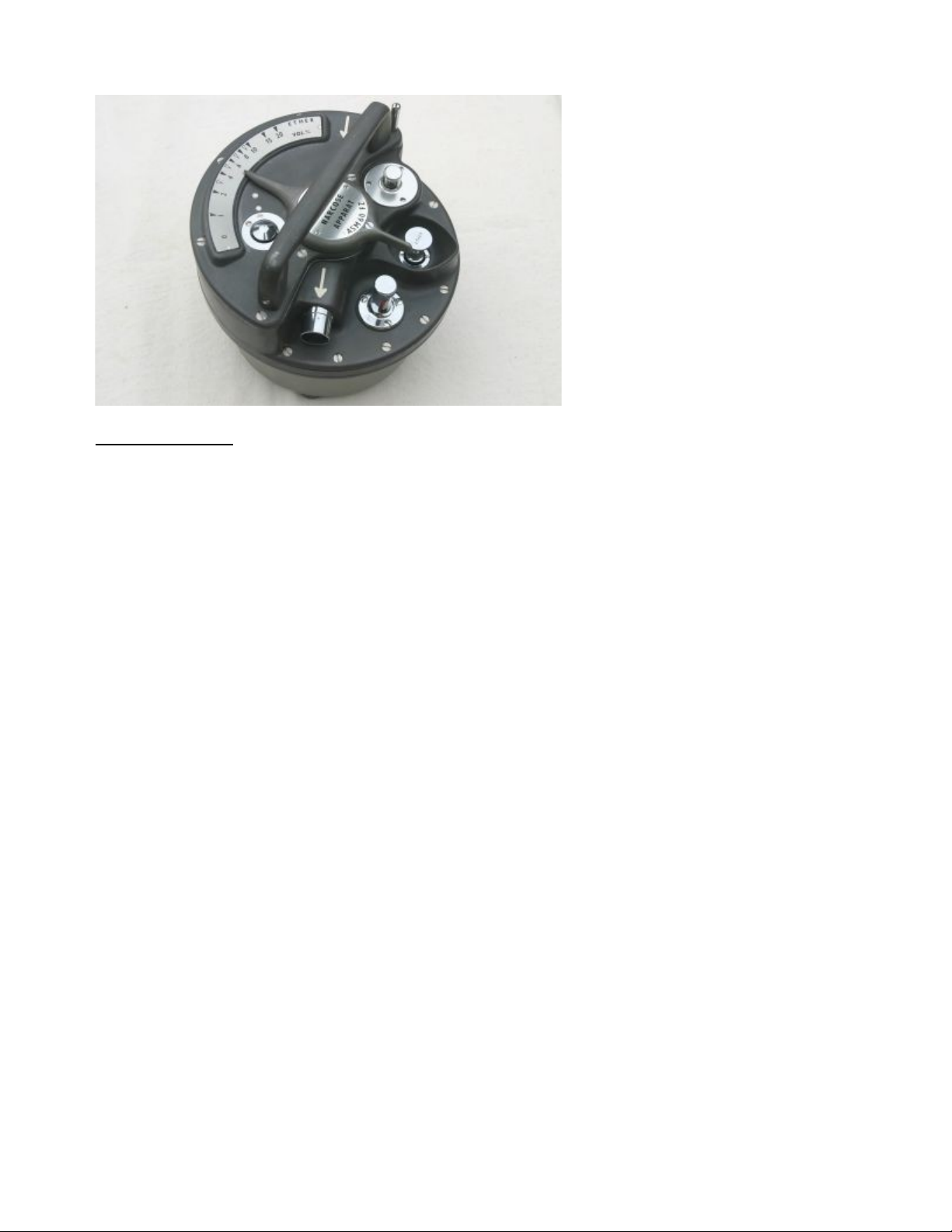
EMO
Service Instruction
created by Frank Weithöner
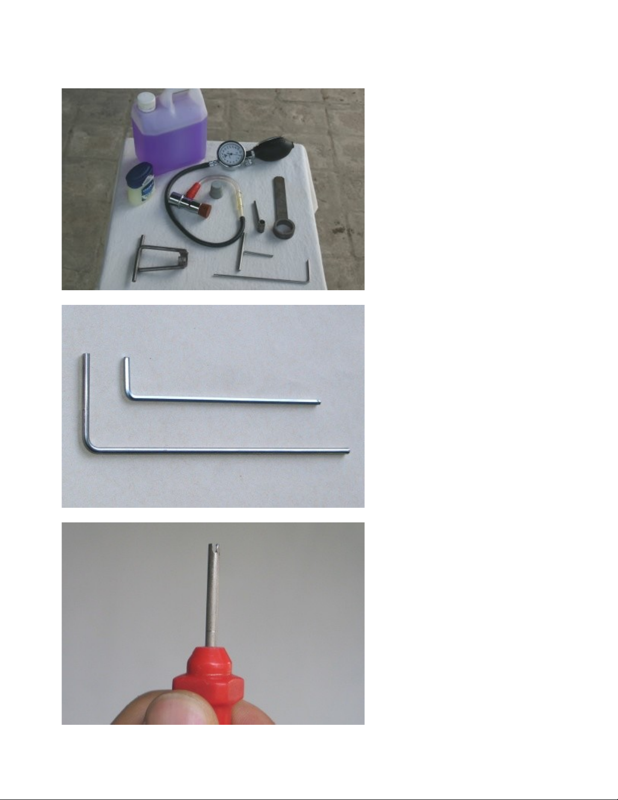
Special Tools
Before starting make sure that all
tools are available. Besides a set of
normal blade screw drivers you will
need some special tools.
1. For opening the EMO:
Allen key 3/32'' (or 2.3mm)
2. For leakage test:
Pressure gauge with plugs
3. Special EMO tools:
- Setting gauge
- Tool for taking out springs
- Tool for taking out the rotor
- Tool for taking out the filler
- Tool for rotor counter nut
- Tool for taking out the filler
4. Alcohol, Vaseline
Here the special EMO tools:
For calibration a setting gauge is
needed. It is a simple piece of bent
metal with a diameter of 2.5mm.
An allen key of the same size also
works fine.
(down the original tool)
For turning the springs out of the
pointer such a tool helps you a lot.
It is an old screw driver (diameter
3mm) with a slit.
If you are experienced you can try
to turn out the springs with strong
forceps. In my opinion it is faster
and easier to build such a tool than
getting out the springs with
forceps.

For holding the counter nut of the
rotor while adjusting you need a
socket with a handle. It's a nice tool
but not really necessary. You also
can hold a simple 8mm socket with
pliers.
This tool helps you to lift out the
rotor. Unfortunately it is difficult to
make and does not work so well.
By now I have no idea how to
create a better tool. Maybe you
have an idea...
The inner diameter is 28mm.
To grab into the notches of the
rotor shaft there must be at least
one nose. In this case it is a 5mm
bolt placed half in the ring.
This a tool for taking out the filler
unit.
It is difficult to make (and to
describe) but you will need it only if
you really want to take out the
filler...

Do you really want to take out the
filler and build it?
Here are the measurements:
Take a 1" pipe (4 mm strong) and
saw a 9mm cut. Now you need 2
little noses with a hight of
approximately 1.5mm. The easiest
way to take material from the pipe
is with a file and leaving the two
noses blank.
The handle is not important but of
course it must be higher than the
filler.
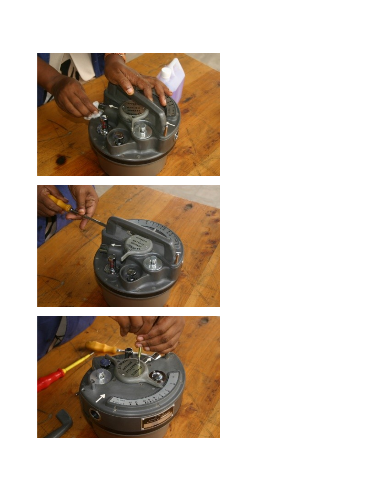
Disassembling Mixing Chamber
Step 1
Clean the whole unit to make sure
that no dirt gets inside while
working with the open unit.
Ether would be perfect, but alcohol
also works.
Step 2
Remove the handle on top.
(2 screws)
Step 3
Remove cover.
(2 screws)
Step 4
Lift out the spring.
Step 5
DO NOT TOUCH THE 3 SCREWS.
Step 6
Remove the screw of the pointer.
It is only a cover screw and hides
an allen key screw which you have
to remove later.
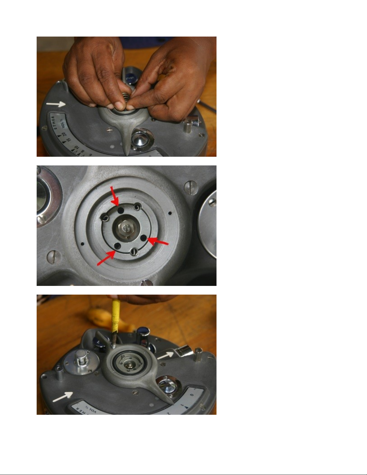
Step 7
Remove the 3 springs. A special
tool is needed.
See Tool Section.
Even with the special tool it is a
very tricky procedure.
Because there is no thread you
have to turn the springs anti-
clockwise to reduce their
diameters while pulling them out.
That sounds easier than it is...
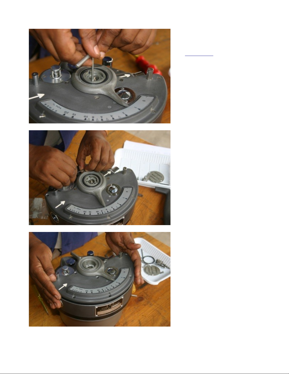
Step 8
Now the pointer turns free, but the
rotor is still attached.
Turn the lever now to 6%.
Now through the hole of the lever
an allen key screw appears (3/32'').
Remove the screw.
Step 9
Remove the lid.
(8 screws)
Don't forget the screw in the centre
under the lever.

Step 10
Now you have to lift out the rotor.
Loosen the nut with the socket key
until the end.
Don't take out the screw
completely.
Step 11
Now screw the axle in the centre
clockwise.
The rotor must come out slowly.
If the rotor is stuck lubrication
around the rotor helps a lot.
Give the oil time to penetrate.
The perfect lubrication is a mixture
oil and ether.
Step12
The rest you have to do with the
special wrench.
Put on the wrench and move the
rotor from side to side and lift it
simultaneously.
Use the wrench only. Do not take a
pair of pliers. You will destroy the
shaft.

Step 13
Clean the rotor and the wall with
ether.
For heavy dirt and particles use
metal polish and a cloth. NEVER
use sand paper or a file. You will
create massive leaks!
Step 14
Now clean the mixing box chamber
and the gasket with ether or
alcohol.
Check gasket for damages.
Step 15
Check the closing mechanism of
proper functionality.
Warning: Do not press the button
too deep. If you do so the gasket
will come out of the button and you
have to dismantle the whole
mechanism to bring it back in
place.
If this already has happened see
the Closing Mechanism section.

Step 16
Lubricate the rotor very slightly
with vaseline.

Assembling Mixing Chamber
Step 17
Set the rotor back in place.
If this is difficult even with vaseline
turn the rotor and try another
position. Note the cuttings of the
rotor and the inlet and outlet of the
chamber and take the original
position.
Step 18
Screw out the screw (anticlockwise) and push the rotor
down.
The exact positioning of the rotor
comes later.
Step 19
Clean the mixing chamber.
Inspect the vaporizer chamber.
If it is very dirty inside fill in ether,
stir up and wash it out through the
filler unit.
Replace the seal.

Step 20
Replace the lid.
(8 screws and
1 allen key screw with
1 cover screw of the pointer)
Step 21
And now the tricky part: Replacing
the springs.
Turn the pointer and rotor into the
correct position so that the holes
for the springs appear.
Now put the springs in. Use the
special tool, turn anti-clockwise
to reduce the diameter of the
springs and press them down.
Step 22
Remember, there are no threads so
do not turn clockwise! You will open
the springs and then the springs
get damaged.
If you already have a damaged
spring with a little luck and skill you
may repair it.

Adjustment Rotor / Level Indicator Unit
Step 23a
For adjusting the rotor you first
have to take out the level indicator.
Therefore you have two options.
First the correct one:
Just loose the 3 screws
(2-4 turns)
and pull the whole unit out.
That is probably difficult because
the unit usually is stuck. So turn it
right and left and rock it slightly.
Use your hands only - no tools.
Step 23b
If it is not possible to take out the
whole unit turn out the screws
completely and lift only the upper
part of the unit out of the EMO.
But watch out for the thin plastic
washer.
The washers hold the distant tubes
in place. They are not so important
but must not fall into the main
chamber.
Clean and check everything,
especially the gasket.
Continue with the rotor adjustment.

Step 24
The adjustment is made by setting
the vertical height of the rotor.
Turn the pointer to approximately
'4'. Insert the setting gauge in the
slit between the rotor and housing.
The rotor is correct adjusted when
the setting gauge fits without
backlash.
To reduce the slit turn the
adjustment screw clockwise. To
open the slit loose the screw and
press the rotor down.
Step 25
After the adjustment secure the
screw and pointer by screwing the
counter nut tighter. Make sure that
the screw is not turning.
Replace the cover of the pointer.
(2 screw)

Temperature Compensating Unit
Step 26
Remove the Temperature
Compensating Unit.
(3 screws)
Be careful. The glass ball is fragile.
Look for dirt and check gasket.
If possible do only a visual
inspection - you can destroy more
than you can repair.
Put it back into its place carefully.

Filler Unit
Step 27
Take out the Filler Unit with the
special tool.
Step 28
Clean everything and check the
function.
The valve should move easily.
Check the gasket.
Put the unit back into the EMO.

Leakage Test
Step 29
For the leakage test you need a
pressure gauge and 2 rubber plugs.
Note: Before using the test
equipment check the pressure
gauge itself for leakage.
Step 30
Connect pressure gauge on one
side and lock the other side with a
plug. Set the pointer between 1
and 20. Do not leave the pointer on
the release valve.
Pump up the system with
approximately 150 mmHg. The
pressure must be stable, but a
pressure loss of up to 10 mmHg in
10 sec. is acceptable.
If the test is OK press the release
valve down. Air must be released
now.
Step 31
But most likely you will have
leakage problems
Do the following:
1. Check your test equipment
2. Screw all screws tight
3. Is the filler closed?
4. Take a closer look to the
release valve. It is always a
source of problems.

Tip: A soap solution spread out with
a brush on all the gaskets is a very
good indicator for leakages. Even
the smallest leakages will
immediately create bubbles.
For the solution just take some
drops of dish washing liquid.

Closing Mechanism (Release Valve)
Step 32
The closing mechanism is the most
sensitive part of The EMO. If
possible leave it in the lid.
But if you have problems (probably
leakages) here are images that
helps you to dismantle and mantle.
Step 33
For removing the closing
mechanism turn the two screws for
2 or 3 turns only.
The third screw is for adjusting.
Do not turn.
Step 33
Two little hooks inside will swing in
and leave the unit free.

Step 34
Clean everything carefully and
watch for damages.
The major problems are the
gaskets. Clean it with alcohol and
put some vaseline on it.
Start with reassembling the silver
knob. First put the gasket around
the knob and insert the knob into
the frame from the inside.
Step 35
As I mentioned above the biggest
problems are the gaskets - the
rubber gaskets as well as the little
plastic washers under the heads of
the crews. They are definitely
damaged. If tightening the screws
with force does not help you may
try liquid gasket maker - but not
too much.
Work carefully that no gasket
maker gets into the chamber.
Step 36
If you use gasket maker don't
forget to seal the screw heads.

Step 37
Remove excessive gasket maker
immediately after assembling and
wait until rubber has dried before
doing another leakage test.
Don't forget to adjust the closing
mechanism after reassembling. You
do this with the adjustment screw.
Check in close and open position.
 Loading...