

Penlon AV-S Service manual (2005)
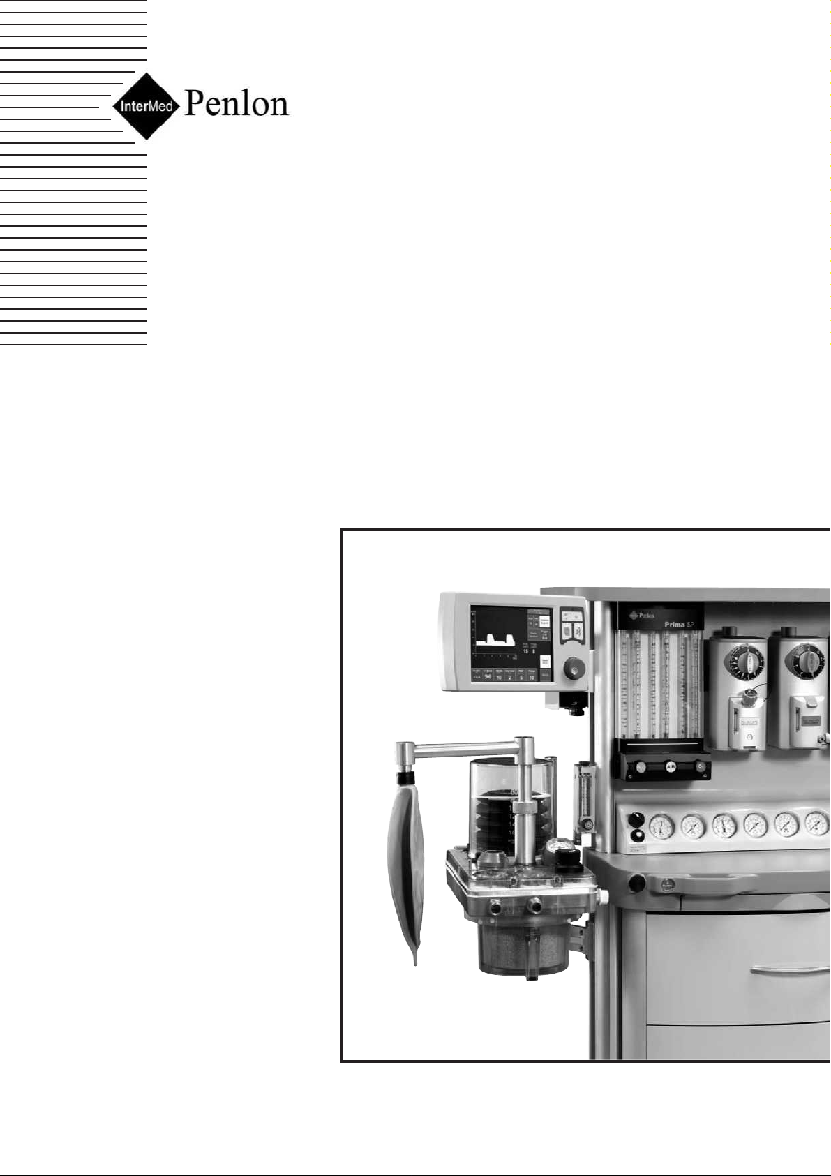
AV -S Ventilator
Remote Display Module and Interface
for use with A200SPAbsorber
Service Manual
Partnership for Life
Draft Copy
July 2005
No update will be given

THE IMPORTANCE OF PATIENT MONITORING
WARNING
Anaesthetic systems have the capability
to deliver mixtures of gases and vapours
to the patient which could cause injury or
death unless controlled by a qualified
anaesthetist.
There can be considerable variation in
the effect of anaesthetic drugs on
individual patients so that the setting and
observation of control levels on the
anaesthesia systems does not in itself
ensure total patient safety.
Anaesthesia system monitors and patient
monitors are very desirable aids for the
anaesthetist but are not true clinical
monitors as the condition of the patient is
also dependent on his respiration and the
functioning of his cardio-vascular system.
IT IS ESSENTIAL THAT THESE ELEMENTS
ARE MONITORED FREQUENTLY AND
REGULARLY AND THAT ANY
OBSERVATIONS ARE GIVEN
PRECEDENCE OVER MACHINE CONTROL
P ARAMETERS IN JUDGING THE STATE OF
A CLINICAL PROCEDURE.

Servicing and Repairs
In order to ensure the full operational life of this
ventilator, servicing by a Penlon-trained
engineer should be undertaken periodically.
The ventilator must be serviced to the following
schedule:
(a) Six monthly service - inspection and
function testing.
(b) Annual / 2 Year / four year service
including component replacement.
Details of these operations are given in this
Manual for the AV-S, available only for Penlon
trained engineers.
For any enquiry regarding the servicing or
repair of this product, contact the nearest
accredited Penlon agent:
or communicate directly with:
Technical Support
Penlon Limited
Abingdon Science Park
Barton Lane
Abingdon
OX14 3PH
UK
Tel: 44 (0) 1235 547076
Fax: 44 (0) 1235 547062
E-mail: technicalsupport@penlon.co.uk
Always give as much of the following
information as possible:
1. Type of equipment
2. Product name
3. Serial number
4. Approximate date of purchase
5. Apparent fault
IMPORTANT
(i)

This manual has been produced to provide
authorised personnel with information on the
function, routine performance, service and
maintenance applicable to the AV-S
Anaesthesia Ventilator.
Information contained in this manual is correct
at the date of publication.
The policy of Penlon Limited is one of continued
improvement to its products.
Because of this policy, Penlon Limited reserves
the right to make any changes which may affect
instructions in this manual, without giving prior
notice.
Personnel must make themselves familiar with
the contents of this manual and the machine’s
function before servicing the apparatus.
Copyright © Penlon Limited, 2005.
All rights reserved.
FOREWORD
(ii)

Page No.
USER RESPONSIBILITY . . . . . . . . . . . . . . . . . . . . . . . . . . . . . . . . . . . . . . . 1
1. WARNINGS AND CAUTIONS . . . . . . . . . . . . . . . . . . . . . . . . . . . . . . . . . . . 2
2. PURPOSE . . . . . . . . . . . . . . . . . . . . . . . . . . . . . . . . . . . . . . . . . . . . . . . . . . . 7
3. DESCRIPTION
3.1 General . . . . . . . . . . . . . . . . . . . . . . . . . . . . . . . . . . . . . . . . . . . . . . . . . . . 8
3.2 Ventilation Cycle . . . . . . . . . . . . . . . . . . . . . . . . . . . . . . . . . . . . . . . . . . . . . 10
3.3 Pneumatic System . . . . . . . . . . . . . . . . . . . . . . . . . . . . . . . . . . . . . . . . . . . 14
3.3.1 System Operation . . . . . . . . . . . . . . . . . . . . . . . . . . . . . . . . . . . . . . . . . . . . 14
3.4 Electrical System . . . . . . . . . . . . . . . . . . . . . . . . . . . . . . . . . . . . . . . . . . . . . 15
3.5 Control Panel . . . . . . . . . . . . . . . . . . . . . . . . . . . . . . . . . . . . . . . . . . . . . 16
3.5.1 Touchscreen Operation and Navigator wheel / push-button . . . . . . . . . . . . 16
3.5.2 User Adjustable Parameters . . . . . . . . . . . . . . . . . . . . . . . . . . . . . . . . . . . . . 17
3.5.3 Operational capability . . . . . . . . . . . . . . . . . . . . . . . . . . . . . . . . . . . . . . . . 17
3.5.4 Output Compensation Functions . . . . . . . . . . . . . . . . . . . . . . . . . . . . . . . 18
3.6 Interface with Prima SP and A200SP . . . . . . . . . . . . . . . . . . . . . . . . . . . . . 19
3.7 Ventilation Modes . . . . . . . . . . . . . . . . . . . . . . . . . . . . . . . . . . . . . . . . . . . . 20
3.7.1 Standby Mode . . . . . . . . . . . . . . . . . . . . . . . . . . . . . . . . . . . . . . . . . . . . . . . . 20
3.7.2 Volume Mode . . . . . . . . . . . . . . . . . . . . . . . . . . . . . . . . . . . . . . . . . . . . . . . . 21
3.7.3 Pressure Mode . . . . . . . . . . . . . . . . . . . . . . . . . . . . . . . . . . . . . . . . . . . . . . 22
3.7.4 Spontaneous Mode . . . . . . . . . . . . . . . . . . . . . . . . . . . . . . . . . . . . . . . . . 23
3.7.5 Advanced Spontaneous Breathing Modes . . . . . . . . . . . . . . . . . . . . . . . . . . . 24
3.7.5.1 SIMV (Synchronised Intermittent Mandatory Ventilation) . . . . . . . . . . . . . 24
3.7.5.2 SMMV (Synchronised Mandatory Minute Ventilation) . . . . . . . . . . . . 25
3.7.5.3 PSV (Pressure Supported Ventilation) . . . . . . . . . . . . . . . . . . . . . . 26
3.7.5.4 PEEP ( Positive End Expiratory Pressure) . . . . . . . . . . . . . . . . . . . . . . 27
3.8 On-screen Menus . . . . . . . . . . . . . . . . . . . . . . . . . . . . . . . . . . . . . . . . . . . . 28
3.9 Spirometry . . . . . . . . . . . . . . . . . . . . . . . . . . . . . . . . . . . . . . . . . . . . . . . . 29
3.10 Display Waveforms . . . . . . . . . . . . . . . . . . . . . . . . . . . . . . . . . . . . . . . . . . 29
3.11 Alarms . . . . . . . . . . . . . . . . . . . . . . . . . . . . . . . . . . . . . . . . . . . . . . . . . . . . 30
3.12 Oxygen Monitor . . . . . . . . . . . . . . . . . . . . . . . . . . . . . . . . . . . . . . . . . . . . 31
3.13.1 System Operation . . . . . . . . . . . . . . . . . . . . . . . . . . . . . . . . . . . . . . . . . . . . 31
3.12.2 The MOX-3 Oxygen Sensor . . . . . . . . . . . . . . . . . . . . . . . . . . . . . . . . . . . . . 31
3.12.3 Menus . . . . . . . . . . . . . . . . . . . . . . . . . . . . . . . . . . . . . . . . . . . . . . . . . . 32
3.12.4 Display . . . . . . . . . . . . . . . . . . . . . . . . . . . . . . . . . . . . . . . . . . . . . . . . . . . . 33
3.12.5 Alarms . . . . . . . . . . . . . . . . . . . . . . . . . . . . . . . . . . . . . . . . . . . . . . . . . . . . 33
3.12.6 Alarm Mute. . . . . . . . . . . . . . . . . . . . . . . . . . . . . . . . . . . . . . . . . . . . . . . . . . 33
4. SPECIFICATION . . . . . . . . . . . . . . . . . . . . . . . . . . . . . . . . . . . . . . . . . . . . . . 34
Ventilator . . . . . . . . . . . . . . . . . . . . . . . . . . . . . . . . . . . . . . . . . . . . . . . . . . 34
Oxygen Monitor . .. . . . . . . . . . . . . . . . . . . . . . . . . . . . . . . . . . . . . . . . . . . . . 37
CONTENTS
(iii)

CONTENTS
(iv)
5. PRE-OPERATION PROCEDURES
5.1 Ventilator Set-up . . . . . . . . . . . . . . . . . . . . . . . . . . . . . . . . . . . . . . . . . . . . . . 39
5.1.1 Mounting the Ventilator . . . . . . . . . . . . . . . . . . . . . . . . . . . . . . . . . . . . . . . 39
5.1.2 Electrical Power Connections . . . . . . . . . . . . . . . . . . . . . . . . . . . . . . . . . . . . . 39
5.1.3 Ventilator Gas Supply . . . . . . . . . . . . . . . . . . . . . . . . . . . . . . . . . . 39
5.1.4 Breathing System Schematic . . . . . . . . . . . . . . . . . . . . . . . . . . . . . . . . . . . . 39
5.1.5 Bellows Drive Gas . . . . . . . . . . . . . . . . . . . . . . . . . . . . . . . . . . . . . . . . . . . 43
5.1.6 Anaesthetic Gas Scavenging System . . . . . . . . . . . . . . . . . . . . . . . . . . . . . . . 43
5.1.7 Printer . . . . . . . . . . . . . . . . . . . . . . . . . . . . . . . . . . . . . . . . . . . . . . . . . . . . 43
5.1.8 Breathing System . . . . . . . . . . . . . . . . . . . . . . . . . . . . . . . . . . . . . . . . . . . 43
5.1.9 Spirometer Connections . . . . . . . . . . . . . . . . . . . . . . . . . . . . . . . . . . . . . . . 44
5.1.10 Pressure Monitor Connections . . . . . . . . . . . . . . . . . . . . . . . . . . . . . . . . . . 46
5.1.11 Bellows Assembly . . . . . . . . . . . . . . . . . . . . . . . . . . . . . . . . . . . . . . . . . . . 47
5.2 Pre-use Checklists . . . . . . . . . . . . . . . . . . . . . . . . . . . . . . . . . . . . . . . . . . . 48
5.2.1 Daily Checklist . . . . . . . . . . . . . . . . . . . . . . . . . . . . . . . . . . . . . . . . . . . 48
5.2.2 Function Test . . . . . . . . . . . . . . . . . . . . . . . . . . . . . . . . . . . . . . . . . . . . . . 49
5.2.3 Weekly Checklist . . . . . . . . . . . . . . . . . . . . . . . . . . . . . . . . . . . . . . . . . . . . 50
5.3 Oxygen Monitor Set-up . . . . . . . . . . . . . . . . . . . . . . . . . . . . . . . . . . . . . . . . 51
5.3.1 Installation . . . . . . . .. . . . . . . . . . . . . . . . . . . . . . . . . . . . . . . . . . . . . . . . . . 51
5.3.2 Calibration . . . . . . . . . . . . . . . . . . . . . . . . . . . . . . . . . . . . . . . . . . . . . . . . . . . 51
5.3.3 Sensor Low Indication . . . . . . . . . . . . . . . . . . . . . . . . . . . . . . . . . . . . . . . . . 53
5.3.4 Setting the High and Low O
2 Alarms . . . . . . . . . . . . . . . . . . . . . . . . . . . . . . . 53
6. SERVICE PROCEDURES
6.1 Service Intervals . . . . . . . . . . . . . . . . . . . . . . . . . . . . . . . . . . . . . . . . . . . . 54
6.2 Control Unit Patient Block Removal . . . . . . . . . . . . . . . . . . . . . . . . . . . . . . 55
7. SERVICE SCHEDULE
Service Schedule . . . . . . . . . . . . . . . . . . . . . . . . . . . . . . . . . . . . . 56
8. PARTS LISTS
Preventive Maintenance Kits . . . . . . . . . . . . . . . . . . . . . . . . . . . . . . 64
Assemblies 65
9. APPENDIX
1. Back-up Battery . . . . . . . . . . . . . . . . . . . . . . . . . . . . . . . . . . . . . . . . . . 78
2. Menu System . . . . . . . . . . . . . . . . . . . . . . . . . . . . . . . . . . . . . . . . . . . . 79
3. Ventilator Spirometry System . . . . . . . . . . . . . . . . . . . . . . . . . . . . . . 82
4. Cleaning . . . . . . . . . . . . . . . . . . . . . . . . . . . . . . . . . . . . . . . . . . . . . . . . . . 85
Outside Surfaces . . . . . . . . . . . . . . . . . . . . . . . . . . . . . . . . . . . . . 85
Bellows and Diaphragm Exhalation Valve . . . . . . . . . . . . . . . . . . . . . 86
Spirometer Sensors . . . . . . . . . . . . . . . . . . . . . . . . . . . . . . . . . . . 86
Patient Connector Block . . . . . . . . . . . . . . . . . . . . . . . . . . . . . . . . . . 86
Sterilisation . . . . . . . . . . . . . . . . . . . . . . . . . . . . . . . . . . . . . . . . . . . 87
Oxygen Monitor - Cleaning and Sterilisation . . . . . . . . . . . . . . . . . . 88
Oxygen Sensor Replacement . . . . . . . . . . . . . . . . . . . . . . . . . . . . . . . 88

This anaesthesia ventilator has been built to
conform with the specification and operating
procedures stated in this manual and/or
accompanying labels and notices when
checked, assembled, operated, maintained
and serviced in accordance with these
instructions.
To ensure the safety of this device it must be
checked and serviced to at least the
minimum standards laid out in this manual.
A defective, or suspected defective, product
must not under any circumstances be used.
The user must accept responsibility for any
malfunction which results from noncompliance with the servicing requirements
detailed in this manual.
Additionally, the user must accept
responsibility for any malfunction which may
result from misuse of any kind or noncompliance with other requirements detailed
in this manual.
Worn, broken, distorted, contaminated or
missing components must be replaced
immediately. Should such a repair become
necessary it is recommended that a request
for service advice be made to the nearest
Penlon accredited agent.
This device and any of its constituent parts
must be repaired only in accordance with
written instructions issued by Penlon
Limited and must not be altered or modified
in any way without the written approval of
Penlon Limited. The user of this equipment
shall have the sole responsibility for any
malfunction which results from improper
use, maintenance, repair, damage or
alteration by anyone other than Penlon or its
appointed agents.
USAand Canadian Federal Law restrict s the
sale and use of this device to, or on the order
of, a licensed practitioner.
Statements in this manual preceded by the
following words are of special significance:
WARNING means there is a
possibility of injury to the
user or others.
CAUTION means there is a possibility
of damage to the apparatus
or other property.
NOTE indicates points of
particular interest for more
efficient and convenient
operation.
Always take particular notice of the
warnings, cautions and notes provided
throughout this manual.
USER RESPONSIBILITY
1

1. WARNINGS AND CAUTIONS
The following WARNINGS and CAUTIONS
must be read and understood before using
this ventilator.
WARNINGS
General Information
1. Personnel must make themselves
familiar with the contents of this
manual and the machine’s function
before using the ventilator.
Before Using the Ventilator
2. Before the ventilator is used clinically
for the first time, verify that the hospital
engineering department has carried out
an earth continuity test.
3. Excessive electronic noise caused by
other poorly regulated devices, such as
an electrocautery unit, may adversely
interfere with the proper functioning of
the ventilator.
To avoid this problem, do not connect
the ventilator’s power cord into the
same electrical wall outlet or adaptor
strip into which an electrocautery unit
is connected.
4. If used with a mains extension cord, the
unit may be subject to electro-magnetic
interference.
5. The driving gas supply must be clean
and dry to prevent ventilator
malfunction.
6. This ventilator is designed to be driven
by oxygen or medical air only. It is
calibrated during manufacture for use
with either gas.
Before the ventilator is used clinically
for the first time, the commissioning
engineer must confirm that the internal
Air/Oxygen switch is set correctly for
the gas that is to be used.
The use of any other gas will cause
inaccurate operation and may damage
the ventilator, resulting in potential
injury to the patient.
7. The driving gas is discharged through
the opening in the back of the ventilator
control unit.
The discharged gas may contaminate
the environment, and should therefore
be extracted using a gas scavenging
system.
8. The bellows can only support
approximately 1 kPa (10 cmH
2
O)
differential positive pressure, above
which it may be dislodged from the
mounting ring, resulting in dangerous
malfunction of the ventilator.
Do not connect a positive end
expiratory pressure (PEEP) valve or
other restrictive device to the exhaust
port on the bellows base.
This would increase the pressure inside
the bellows and the bellows could
detach from the base, causing serious
malfunction.
9. Breathing System
The breathing system which conveys
gases from the anaesthetic machine to
the patient, and disposes of expired
gases, must conform to the
requirements of ISO 8835-2.
Because breathing systems require
frequent cleaning and disinfection they
are not a permanent part of the
anaesthetic ventilator and therefore
cannot be directly under the control of
the anaesthetic ventilator manufacturer.
However, we strongly recommend that
only breathing systems which have
been approved and authorised by
Penlon for use with AV-S should be
employed.
Do not use conductive breathing
system hoses.
When mechanical ventilation is
employed the patient breathing system
must be connected directly to a
pressure relief valve to prevent the
possibility of barotrauma.
10. Do not connect a spirometer to the
exhaust port on the bellows base.
The device will not measure exhaled
volumes in that position.
2

11. The operation of each alarm function
should be verified daily.
Periodically check the alarms at
clinically suitable intervals. If the
audible alarm or the visual indicator of
any alarm function fails to activate
during any alarm condition or fails to
reset after the alarm has been cleared,
refer the unit to an authorised service
technician.
12. Before using the ventilator check that
all connections are correct, and verify
that there are no leaks.
Patient circuit disconnects are a hazard
to the patient. Extreme care should be
taken to prevent such occurrences.
It is recommended that Penlon
Safelock fittings are used throughout
the breathing circuit.
Using the Ventilator
13. The AV-S ventilator is not intended for
use in intensive care applications.
14. This apparatus must not be used with,
or in close proximity to, flammable
anaesthetic agents.
There is a possible fire or explosion
hazard.
15. Anaesthesia apparatus must be
connected to an anaesthetic gas
scavenging system (AGSS) to dispose
of waste gas and prevent possible
health hazards to operating room staff.
This requirement must be observed
during test procedures as well as
during use with a patient.
The scavenging transfer and receiver
system must conform to ISO 8835-3.
Any problem arising from an
improperly functioning scavenging
system is solely the user’s
responsibility.
Do not use a scavenging system that
restricts drive gas flow when negative
pressure is exerted on it.
16. When the ventilator is connected to a
patient, it is recommended that a
qualified practitioner is in attendance
at all times to react to an alarm or other
indication of a problem.
17. In compliance with good anaesthesia
practice, an alternative means of
ventilation must be available whenever
the ventilator is in use.
18. It is recommended that the patient
oxygen concentration should be
monitored continuously.
19. If the drive gas supply pressure drops
below a nominal 241 kPa (35 psi), the
LOW DRIVE GAS SUPPLY alarm will
activate both audibly and visually.
Patient minute volume may be reduced
due to lowered flow rates
20. An audible alarm indicates an
anomalous condition and should never
go unheeded.
21. The characteristics of the breathing
circuit connected between the
ventilator and the patient can modify or
change patient ventilation.
To assist the maintenance of the
delivered patient tidal volume, the
ventilator control system software
includes:
A) a compliance compensation
algorithm,
B) a fresh gas compensation
algorithm.
However, patient ventilation must be
monitored independently from the
ventilator.
It is the responsibility of the user to
monitor patient ventilation.
22. Care must be taken to ensure that the
flow sensors are connected correctly
to the inspiratory and expiratory ports
of the absorber.
23. The Vent Inop (ventilator inoperative)
alarm indicates that one of the
following conditions has occurred:
a) The drive gas solenoid has failed.
b) The flow control valve has failed.
c) Internal electronic fault.
d) Internal electrical fault.
e) Software error.
Note that if a ventilator error is
detected, ‘Ventilator Inoperative’will be
displayed on the front control panel
display.
WARNINGS AND CAUTIONS
3

24. The High and Low Airway Pressure
Alarms are important for patient care.
It is important that the sensor is
properly located in the expiratory limb
of the circuit - refer to section 5.1.10.
25. The patient must be continuously
attended and monitored when
Advanced Breathing Modes are in use.
User Maintenance
Control Unit
26. Opening the control unit by
unauthorised personnel automatically
voids all warranties and specifications.
Prevention of tampering with the
control unit is exclusively the user’s
responsibility. If the control unit seal is
broken, the manufacturer assumes no
liability for any malfunction or failure of
the ventilator.
27. For continued protection against fire
hazards, replace the two fuses only
with the identical type and rating of
fuse.
See section 4 for fuse rating.
28. If the internal battery is fully
discharged, the ventilator will not
function in the event of mains power
failure. The battery must be recharged
before the ventilator is used clinically,
otherwise backup cannot be
guaranteed.
See Appendix for battery maintenance.
See also CAUTION No. 7.
Used or defective batteries must be
disposed of according to hospital,
local, state, and federal regulations.
29. No oil, grease or other flammable
lubricant or sealant must be used on
any part of the ventilator in close
proximity to medical gas distribution
components.
There is a risk of fire or explosion.
30. Exterior panels must not be removed
by unauthorised personnel and the
apparatus must not be operated with
such panels missing.
There is a possible electric shock
hazard.
31. Check that the cable between the
control unit and remote display screen
unit is connected before use.
Always use a cable type recommended
by the manufacturer.
Bellows Assembly
32. The valve seat on the patient gas
exhalation diaphragm valve in the base
of the bellows assembly must be
cleaned regularly - see section 6.2.
Failure to keep the valve seat clean
could result in the diaphragm sticking,
thus preventing exhalation.
Great care must be taken not to
damage the precision surface of the
valve seat on the patient gas exhalation
diaphragm valve in the base of the
bellows assembly.
Never use any hard object or abrasive
detergent to clean it; use only a soft
cloth.
If the valve seat is damaged, the valve
will leak and may cause serious
ventilator malfunction.
WARNINGS AND CAUTIONS
4

CAUTIONS
1. Do not sterilise the ventilator control unit.
The patient block assembly must be
removed from the control unit before
sterilisation ( see section 6.2.4).
All other internal components are not
compatible with sterilisation techniques
and damage may result.
2. For ventilator components which require
sterilisation, peak sterilisation
temperatures should not exceed 136oC
(275oF) to prevent possible damage.
(See section 6).
3. Those parts suitable for ethylene oxide
sterilisation should, following sterilisation,
be quarantined in a well ventilated area to
allow dissipation of residual gas absorbed
by the components.
Follow the steriliser manufacturer’s
recommendations for any special aeration
periods required.
4. The exhalation valve located in the
bellows base assembly and the paediatric
bellows adaptor must be cleaned and
sterilised separately. See section 6.
5. Care must be taken not to let any liquid
run into the control unit; serious damage
may result.
6. Always check for correct fitment, and carry
out a full function test before clinical use, if
the bellows has been removed and
refitted for any reason. See section 6.
7. Damage may occur to the battery if it is
allowed to remain in a discharged state.
Check the battery frequently if the
ventilator is in storage (see Appendix 1).
8. Fresh gas compensation is disabled if :
a) The spirometry system is turned OFF
through the menu system, or
b) The spirometry system is not functioning
correctly.
9. Fresh gas mixture compensation is disabled
if :
a) The spirometry system is turned OFF
through the menu system, or
b) The spirometry system is not functioning
correctly.
c) The O2 monitor is switched OFF.
10. Circuit compliance is not activated until
Fresh Gas Compensation is switched
OFF.
NOTES
1. The term ‘cycle’ is used to designate the
transition to the exhalation phase.
2. The term ‘trigger’ is used to indicate the
transition to the inhalation phase.
WARNINGS AND CAUTIONS
5

Oxygen Monitor
WARNINGS
1. We recommend calibration of the
oxygen monitor every time the system
is turned on, as a safety precaution.
2. Do not attempt to open the fuel cell.
The sensor contains small quantities
of :
a) electrolyte, classified as a harmful
irritant which is potentially hazardous,
and
b) lead.
Used or defective cells must be
disposed of according to hospital,
local, state, and federal regulations.
3. ALWAYS check the integrity of the
sensor assembly before use.
4. Once exhausted, the sensor must be
disposed of according to hospital,
local, state and federal regulations.
5. The sensor measures oxygen partial
pressure, and its output will rise and
fall due to pressure change.
An increase in pressure of 10% at the
sensor inlet will produce a 10%
increase in sensor output.
CAUTIONS
1. Only use low temperature ethylene oxide
sterilisation for the oxygen sensor.
The sensor is not compatible with other
sterilisation techniques - damage may
result.
Do not sterilise any other components.
2. Do not autoclave or expose the sensor to
high temperatures.
3. If the sensor shows signs of being affected
by condensation, dry the sensor with soft
tissue.
Do not use heat to dry the sensor.
6
NOTES
1. The O2 SENSOR FAULT alarm indicates
that one of the following conditions has
occurred.
a) Internal electrical fault
b) Software/electronics fault
c) Oxygen sensor fault.
2. The concentration read-out may, in
certain conditions of excess pressure,
show a value above 100%.
To accommodate these conditions it is
possible to set the high alarm value up to
105% (see section 5).
3. To maintain maximum sensor life:
i) always switch off the anaesthetic
machine after use, to ensure that the basal
flow ceases.
ii) disconnect the breathing circuit after
use.
4. The accuracy of flow and volume
measurements may be reduced if the
oxygen monitor is not in use.
5. Fresh gas mixture compensation is disabled
if the oxygen monitor is switched OFF.
WARNINGS AND CAUTIONS - Oxygen Monitor

The AV-S Ventilator is a software controlled,
multi-mode ventilator, designed for
mechanical ventilation of adult and
paediatric patients under general
anaesthesia.
In addition, in spontaneous mode, it can be
used to monitor spontaneously breathing
patients
It is designed for use in closed-circuit
anaesthesia and also to drive a Mapleson D
circuit.
Indications for use of the device:
The AV-S Ventilator is intended to provide
continuous mechanical ventilatory support
during anaesthesia. The ventilator is a
restricted medical device intended for use by
qualified trained personnel under the
direction of a physician. Specifically the
ventilator is applicable for adult and
paediatric patients.
The ventilator is intended for use by health
care providers, i.e. Physicians, Nurses and
Technicians with patients during general
anaesthesia.
The AV-S ventilator is not intended for use in
intensive care applications.
Oxygen Monitor
The Oxygen Monitor is intended to
continuously measure and display the
concentration of oxygen in breathing gas
mixtures used in anaesthesia, and is
intended for adult and paediatric patients.
The oxygen monitor is an integral part of the
ventilator.
The oxygen monitor is intended for use by
health care providers, i.e. Physicians,
Nurses and Technicians for use with patients
during general anaesthesia.
2. PURPOSE
7
3.1 General Description
The AV-S Ventilator is a pneumatically
driven, software controlled, multi-mode
ventilator.
The ventilator is a time-cycled,
volume/pressure controlled, and pressure
limited.
The ventilator has compliance compensation
and a user selectable option of an inspiratory
pause fixed at 25% of the inspiratory time.
In addition, fresh gas compensation and
user selectable gas mixture compensation is
a standard feature.
Ventilation Modes
Volume Mode - continuous mandatory
ventilation
Pressure Mode - pressure controlled
ventilation
Spontaneous, with advanced features SIMV, SMMV, PSV
PEEP
Patient Monitoring
Airway pressure, measured from the
expiratory limb of the breathing circuit.
Tidal volume and Minute Volume
measurement is provided by a dual
spirometry system
An integral oxygen monitor system
measures oxygen concentration in the
breathing circuit inspiratory limb.
The print function provides a permanent
record of function activity for up to eight
hours during a procedure, or can be used to
record waveforms.
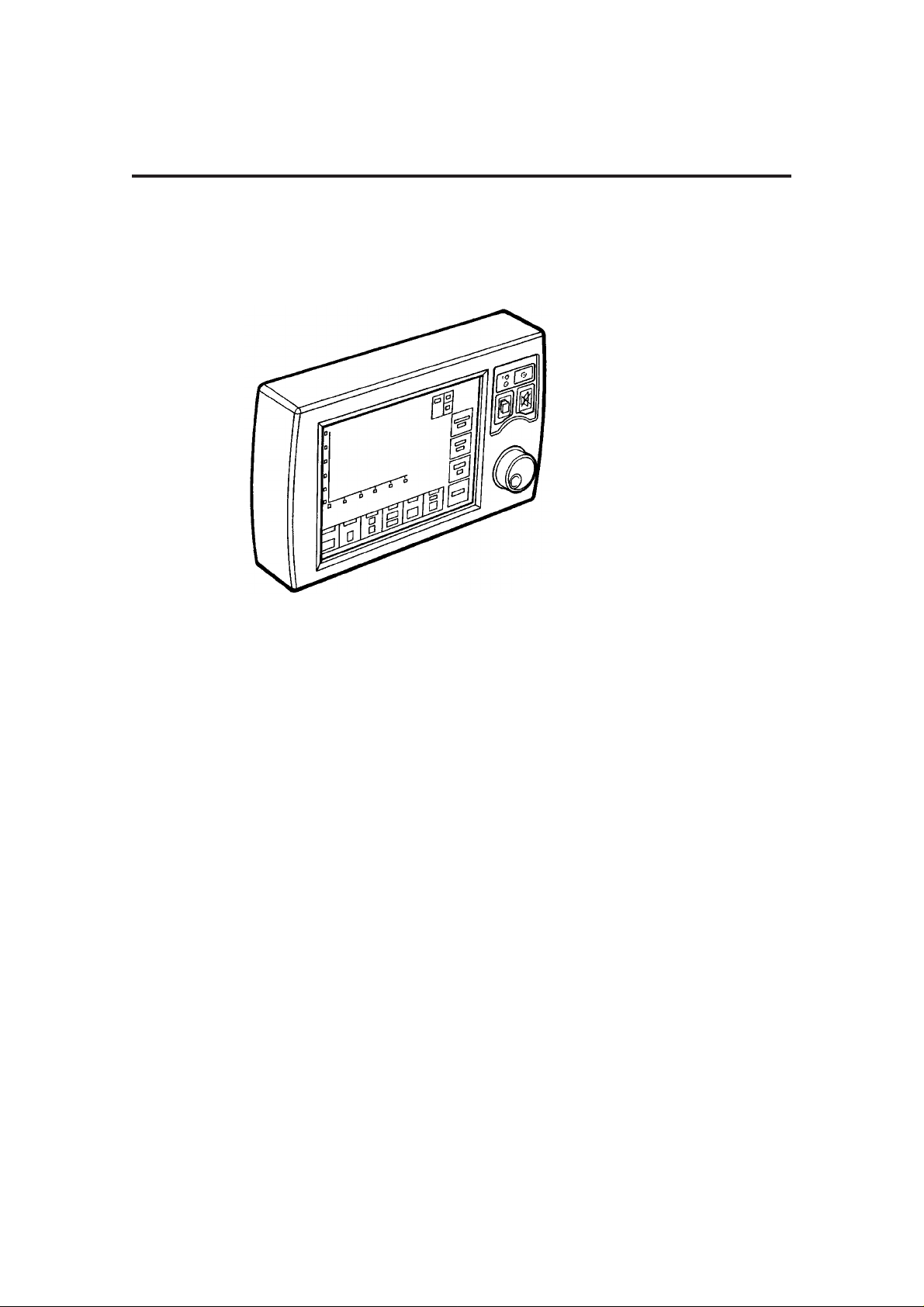
Screen
210 mm (8.4 inch) high definition, colour TFT
screen, with single/dual waveform display.
3. DESCRIPTION
8
AV-S Ventilator
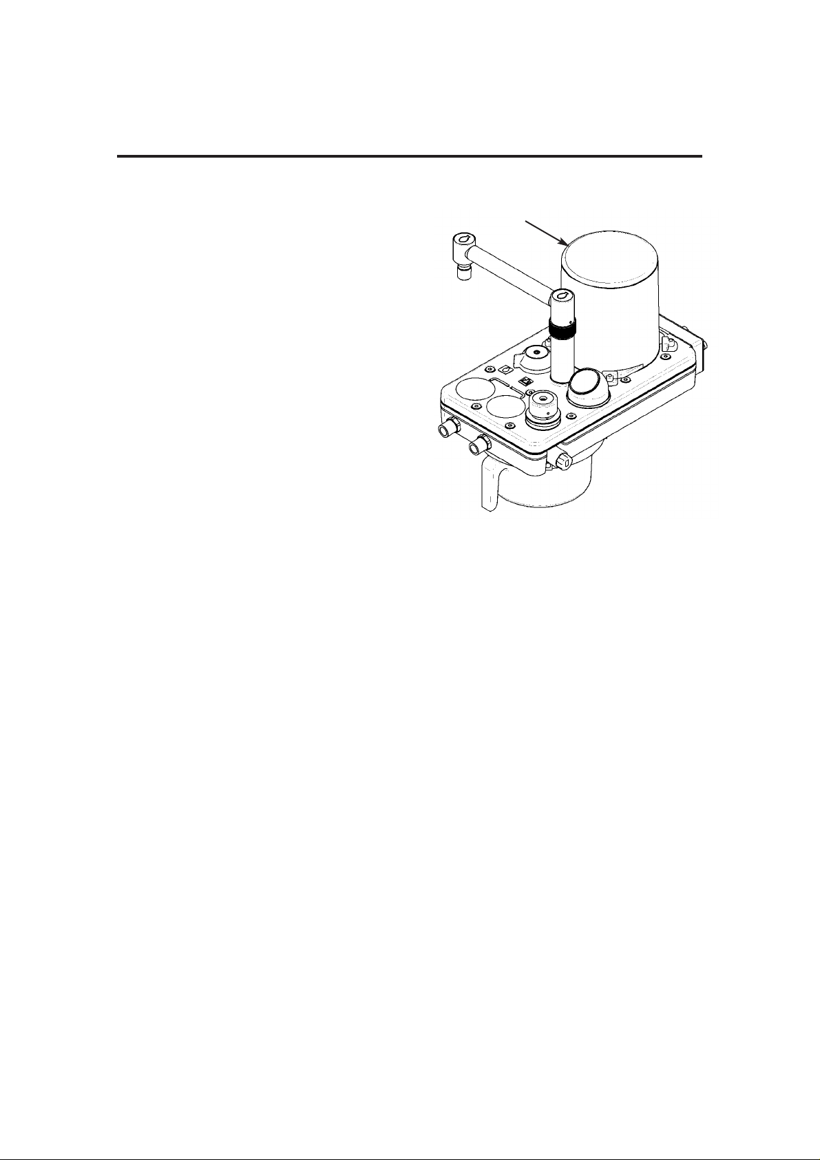
Bellows unit
The bellows unit (1) is built into the A200SP
absorber.
A paediatric bellows assembly is available as
an option
Mounting options
The AV-S integral screen and control unit can
be mounted securely on the anaesthetic
machine shelf or side bracket.
Drive gas supply
The supply must be at 310 to 689 kPa (45 to
100 psi ).
The ventilator drive gas supply can be oxygen
or air.
Note that the drive gas is specified by the
customer prior to delivery. Conversion from
one drive gas to another must be carried out by
a Penlon-trained service engineer.
DESCRIPTION
9
1
10
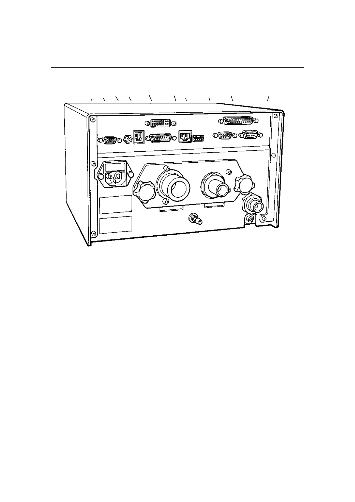
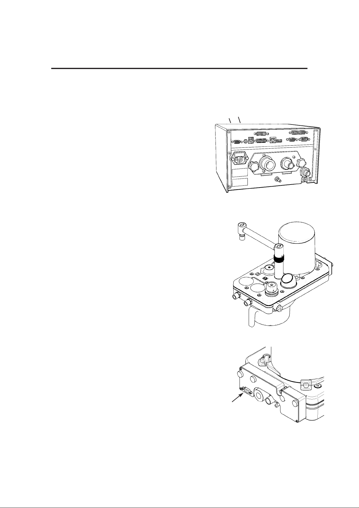
Control Unit
Rear Panel
Interface and Parameter inputs
5. A200SP Absorber Bag/Vent
switch interface
Spirometer connector
6. Prima SP Interface connector
7. Pressure Monitor Port
8. Input socket - Oxygen monitor
sensor
Data and Printer Ports
9. Data Output
10. Output to remote screen
11. Ethernet
12. USB
13. VGA
14. Printer port
15. RS232
NOTE
USB port is for use by Penlon-trained
engineers only.
All other data ports are read only.
For further information, please contact
Penlon Technical Support.
Gas Connections
1. Ventilator drive gas inlet
- connect to anaesthetic machine
auxiliary gas outlet
2. Bellows Drive Gas Output
- connect to bellows
( on Prima SP with A200SP absorber,
connect to absorber - see section 5.1.5)
3. Outlet - Exhaust Valve
Electrical Connection
4. Electrical mains input and fuse unit
DESCRIPTION
2
7
3
13 14 15
12
1110
9
8
6
5
4
1
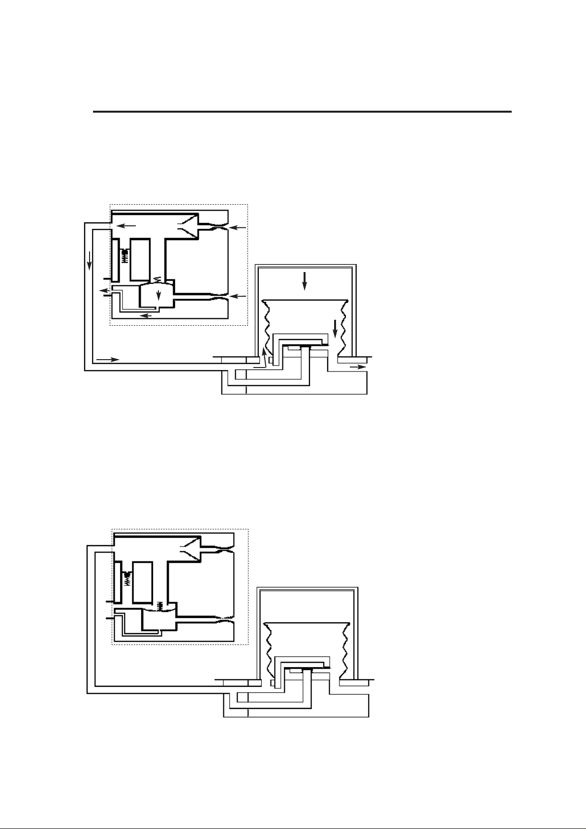
3.2 Ventilation Cycle
This section provides a simplified description of the ventilation cycle.
1. Inspiratory Phase
The inspiratory proportional
valve (1) in the control unit
opens, and bellows drive
gas is delivered to the
bellows housing (2).
The expiratory proportional
valve (3) opens and gas
flows through the bleed
valve. The back pressure
ensures that the exhaust
valve (4) is kept closed
Drive gas pressure builds
up above the bellows, which
starts to move down.
The diaphragm (5) in the
bellows assembly base is
held closed, and patient gas
is forced out of the bellows
base (6) into the breathing
system.
2. Beginning of
Expiratory Phase
The Inspiratory (1) and
Expiratory (3) proportional
valves close and the exhaust
valve (4) opens. Patient gas
returns to the bellows. As
the bellows rises, redundant
drive gas is pushed out
through the exhaust valve.
DESCRIPTION
11
1
4
4
5
6
2
3
3
1
3
1
4
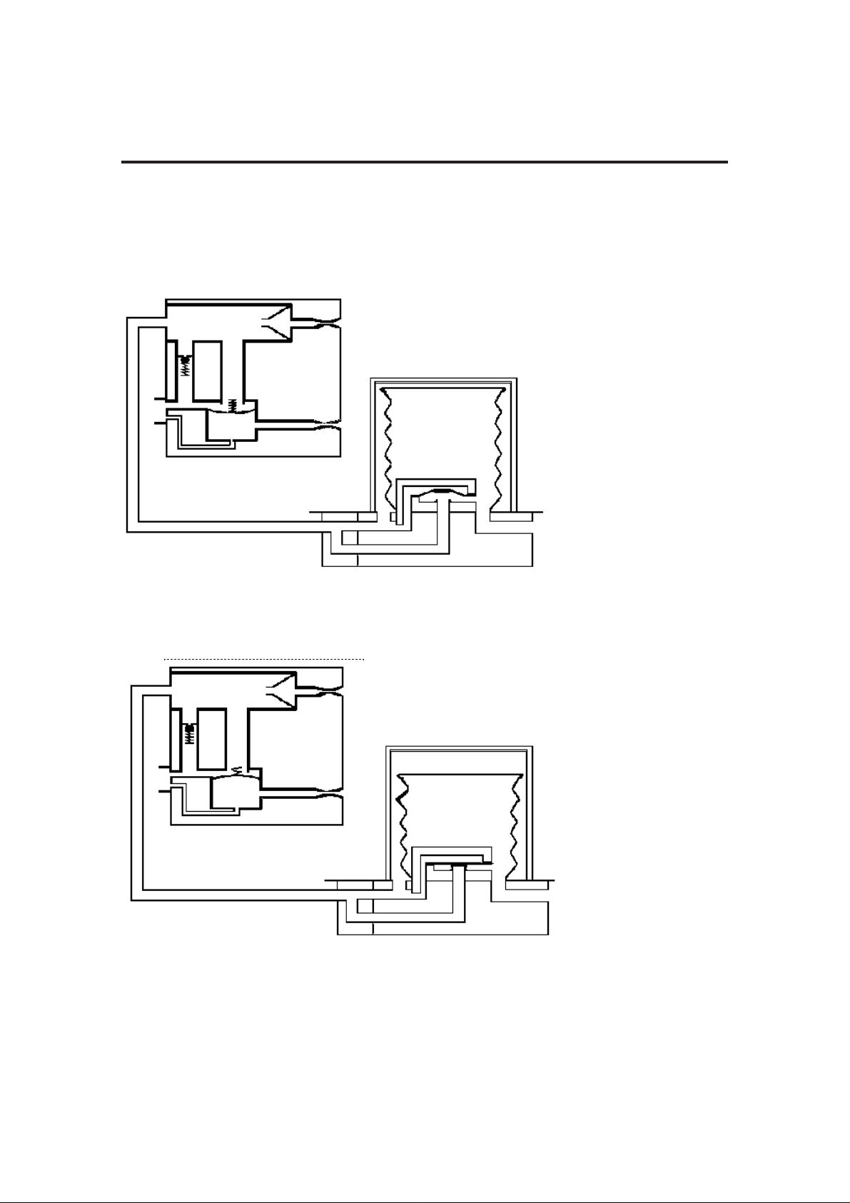
DESCRIPTION
3. End of
Expiratory Phase
With the bellows at the top
of its housing fresh gas
continues to flow. To
prevent a high pressure
build up the exhalation
diaphragm (5) lifts and
allows gas to exit through
the exhaust valve (4).
4. PEEP
Positive End
Expiratory
Pressure
(user selectable)
During PEEP the Exhalation
Proportional valve (3)
applies PEEP pressure plus
20 cmH2O to the exhaust
valve, which remains closed
at this stage.
As fresh gas flows in the
patient circuit, any pressure
increase above PEEP
pressure in the bellows will
cause gas to bleed past the
exhaust valve (4).
A continuous flow from the
Inspiratory proportional
valve (1) ensures that any
fall in pressure is
compensated by driving the
bellows as required.
12
5
4
13
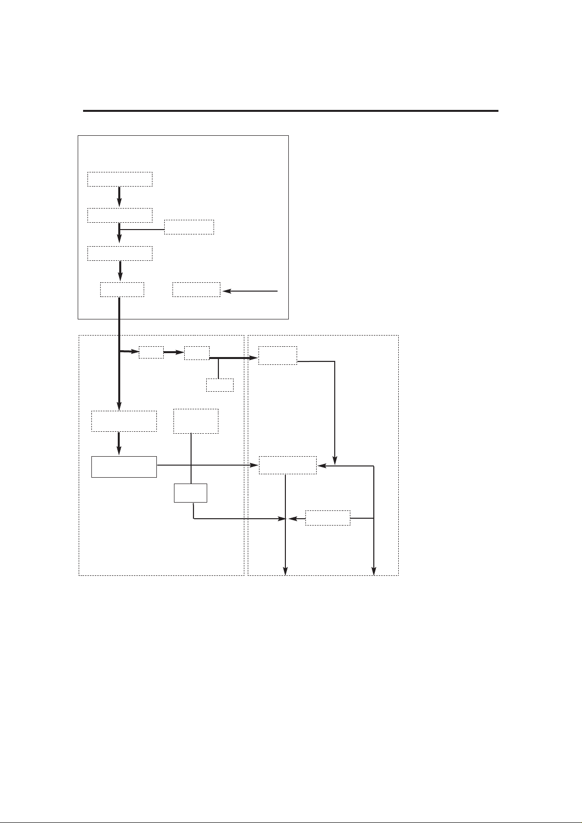
DESCRIPTION
A
Pneumatic Flow
Diagram
C
1817
5
8
14
9
12
6
16
13
15
11
7
1
2
10
4
3
B
0 - 80 cmH
2O
100 cmH
2O
0 - 90 cmH2O
241 kPa (35 psi)
3 to 7 bar

3.3 Pneumatic System
3.3.1 System Operation
Refer to the pneumatic system diagram on the
previous page.
A) Gas inlet manifold block
The AV-S Ventilator is designed to operate on a
310 - 689 kPa (45 -100 psi) drive gas supply
(oxygen or air - to customer’s requirement).
1. DISS Connector
The gas source is connected to the
DRIVE GAS SUPPLY fitting on the rear of
the ventilator control unit.
The gas supply should be capable of a
flow rate of 80 L/min while maintaining a
minimum pressure in excess of 310 kPa
(45 psi).
2. Filter
The drive gas is filtered with a 40-micron
Input Gas Filter which protects the
pneumatic components from incoming
particulate matter.
3. The Low Supply Pressure Detector
The pressure switch is set at a
predetermined level to detect a loss or
reduction of the input gas source
pressure.
When the pressure falls below 235 kPa
(35 psi ± 1 psi), the LOW SUPPLY
PRESSURE indicator will be displayed
and the high priority audible alarm will
activate.
4. Input Pressure Regulator
Regulates the input drive gas to 260 kPa
± 21 kPa (38 psi ± 3 psi).
5. Cut-off Valve
The valve isolates the the gas supply :
a) when the ventilator is switched off
b) when a fault condition occurs.
6. Airway Pressure Sensor
Connected to expiratory limb of breathing
circuit.
DESCRIPTION
14
B) Pneumatic Control Manifold Block
7. Inspiratory Proportional Valve
8.
Flow Sensor
9. Drive Gas pressure Sensor
10. Low Pressure Regulator
11. Expiratory Proportional Valve
12. PEEP pressure sensor
13. Restrictor
The restrictor allows a flow of up to 2 L/min
(<2 L/min bleeding)
C) Exhaust Manifold Block
14. Check Valve
15. Diaphragm Valve
16. Pressure Relief valve
Set to 100 cmH
2O
17. Exhaust Port ( to AGSS)
18. Bellows drive gas outlet (to bellows
assembly)

3.4 Electrical System
Mains Supply
The mains supply inlet is designed for
connection to any mains voltage from 100 to
240 VAC and a frequency of 50 to 60 Hz,
without any adjustment.
The connector is a standard IEC type.
Back-up Battery
In the event of mains electrical failure, the backup battery cuts in automatically.
A fully charged battery will power the ventilator
for approximately 30 minutes.
See Appendix 1 for battery care procedures.
DESCRIPTION
15
VmSET
Litres
3.6
VmMEAS
Litres
3.6
SET
BPM
6
Insp Time
Sec
2
PEEP
cmH2O
5
LIMIT
cmH2O
38
Spont
Mode
Pmean
cmH2O
10
Pmax
cmH2O
24
Standby
Freeze
Waveform
SMMV
%O2 100
33 20
Trigger
cmH2O
-1.0
cm H2O
secs
AV-S
Touchscreen control
1
4
3
5
2
Gas Mixture
O2 + air
.
.
IO
o
o
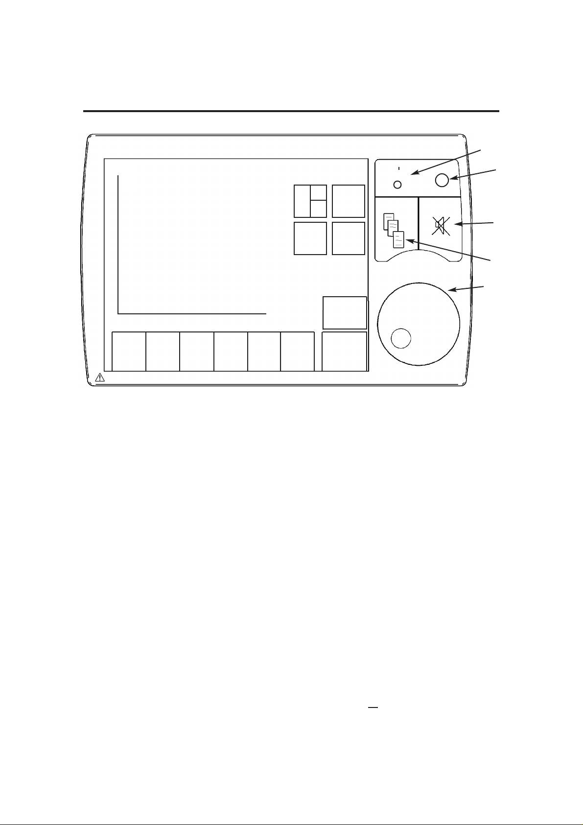
DESCRIPTION
5. Navigator Wheel and Press Button
Turn the wheel to select a function or
parameter, or to alter the value of an
active parameter.
Press to confirm the setting.
3.5.1.2 Selecting Functions and
Parameters
The functions/parameters shown on the
screen can be activated as follows:
a) touch the screen at the appropriate tab
area.
b) rotate the navigator wheel and press it
when the indicator arrow is on the required
parameter tab
Note that parameters default to factory-set
values when the ventilator is switched on
and no further user selection is made.
3.5.1.3 User Adjustable Parameters
Variable parameters can be altered by
rotating the navigator wheel.
When the required value is displayed, press
the active tab or
the wheel to confirm the
setting.
3.5 Control Panel
3.5.1 Touchscreen and Navigator
Wheel / Push Button
3.5.1.1 Control Panel
1. On/Off control
Switch On:
Short internal test sequence
Switch Off:
5 second power down sequence with
audible tones
2. Status indicators for electrical power
(mains/battery supply)
Yellow indicator
- illuminated whenever power is
applied to the unit and internal battery
is being charged
Green indicator
- illuminates when the unit is switched
on, .
3. Menu switch
The menu function provides access to
user and service pages
4. Alarm mute switch
30 second or 120 second Alarm
silence, depending on alarm status.
Note also that some alarms are not
mutable (see 3.11).
16
3.5.2 User Adjustable Parameters
Tidal Volume Range 20 - 1600 ml
Rate 4 - 100 bpm
I:E Ratio 1:0.3 to 1:8
PEEP 4 - 30 cmH2O
Can be set to OFF
Pressure Limit
Volume mode: 10 - 80 cmH2O
Pressure mode: 10 - 70 cmH2O
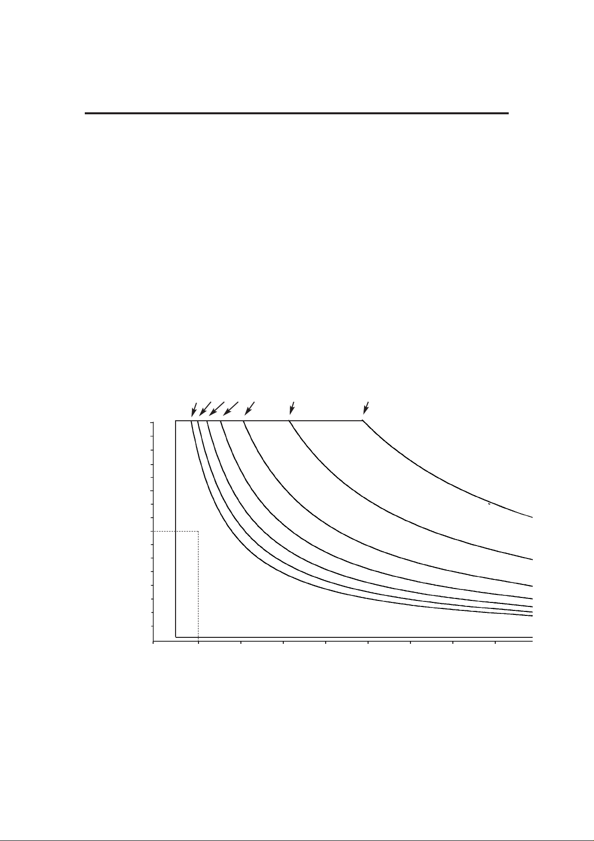
3.5.3 Operational Capability
Tidal Volume, Rate, and I:E ratio settings are all limited by a
maximum inspiratory flow of 75 L/min.
DESCRIPTION
17
0.1
0.2
0.4
0.3
0.6
0.5
1.6
1.5
1.4
1.3
1.2
1.1
1.0
0.9
0.8
0.7
0 10 20 30 40 50 60 70 80
1:6 1:5 1:4 1:3 1:2 1:1 1:0.3
Rate (bpm)
Tidal
Volume
(litres)
(Vt)
I:E Ratio
The ventilator is capable of operating at the volumes and rates below each I:E ratio curve.
Example
1. Select required volume (Vt) (e.g. 0.8 L)
2. Select rate (e.g. 10 bpm).
3. Select I:E ratio of 1:2.
The point X on the graph lies beneath the 1:2 ratio curve, and is therefore within the
ventilator’s capability
.
X

3.5.4 Output Compensation
Functions
WARNING
The AV-S automatically compensates for fresh
gas (spirometry On), fresh gas mixture
(spirometry and oxygen monitor On), and
altitude.
However, the actual tidal volume delivered to the
patient may be different to the ventilation
parameters set by the user, due to:
A) an extreme compliance condition,
B) a substantial system leak,
C) patient circuit pressure effects, or
D) extreme fresh gas flows
In addition, high fresh gas flows will lead to an
increased Vt being delivered to the patient.
The patient must
be monitored independently
from the ventilator.
It is the responsibility of the user to monitor the
patient for adequate ventilation.
Fresh Gas Compensation
Adjusts delivered volume up to 60%
Alarms if measured volume is 50% different
than set volume
User adjustable
NOTE
Fresh gas compensation is disabled if :
a) The spirometry system is turned OFF through the
menu system, or
b) The spirometry system is not functioning correctly .
Fresh Gas Mixture Compensation
- models with Spirometry
The spirometry system compensates for fresh gas
mixture - the user must access the menu system and
select the gas mixture that will be used for each
clinical procedure.
NOTE
Fresh gas mixture compensation is disabled if :
a) The spirometry system is turned OFF through the
menu system, or
b) The spirometry system is not functioning correctly .
If the O2 monitor is switched OFF, a 40%/60%
mixture of O2/N2O is assumed.
Altitude Compensation
Monitors ambient pressure
Adjusts delivered volume accordingly
DESCRIPTION
18
A
B
3.6 Interface to Prima SP2/3 and A200SP
The AV-S is designed to interface with the Prima
SP Anaesthetic Machine and the A200SP
Absorber.
3.6.1 Prima SP Interface
The interface cable links the socket (A) on the
control panel to a socket on the rear panel of the
anaesthetic machine.
a) Turn the Prima Sp Gas Delivery Switch to
ON.
The ventilator will power-up.
b) While the Prima SP power is ON, the
Ventilator can be turned OFF and ON, using
the ventilator On/Off switch, as described in
section 3.5.1.
c) Turn the Prima SP Gas Delivery Switch to
OFF. The ventilator will power-down.
3.6.2 A200SP Absorber Interface
The interface cable links the socket (B) on the
control panel to a socket (C) at the rear of the
absorber.
a) The A200SP is fitted with fitted with a sensor
that detects the position of the absorber
bag/vent control (D).
The sensor signal cabling is routed internally
to connector (C) and a second cable runs to
the the rear of the AV-S control unit.
b) Operation of the Bag/Vent control will trigger
automatic Mode switching on the AV-S
ventilator, as follows:
i) If the Absorber Bag/Vent control is moved
from Vent to Bag, the ventilator will change
from Volume Mode, or Pressure Mode, into
Spontaneous Mode.
ii) Switching the absorber Bag/Vent control
from Bag to Vent:
The ventilator will reset from Spontaneous
Mode to the previously set active mode.
iii) If the ventilator is in any mode other than
those detailed above, operation of the
absorber Bag/Vent control will not affect the
ventilator.
NOTE This function can be enabled/disabled
through the AV-S on-screen menus (Service Submenu, see appendix).
19
DESCRIPTION
D
C

3.7 Ventilation Modes
3.7.1 Standby Mode
Allows parameters to be set.
Some patient alarms are active:
High airway pressure (at 80 cmH2O)
High/Low O2
Negative pressure
Incorrect Rate/Ratio
DESCRIPTION
20

3.7.2 Volume Mode
The ventilator delivers a mandatory set
volume of gas at preset, fixed breath
intervals.
The Patient is making no respiratory effort.
3.7.2.1 Fresh Gas Compensation
Adjusts delivered volume up to 60%
This delivered volume will consist of the
volume delivered from the ventilator bellows
plus the fresh gas flow from the anaesthetic
machine fresh gas supply, minus any
compliance loss and minus any leak.
This gives a total actual inspired tidal
volume.
An alarm is triggered if measured volume is
50% different than set volume
User adjustable
Altitude Compensation
Monitors ambient pressure
Adjusts delivered volume accordingly
3.7.2.2 Operating Functions
Inspiratory Pause function: Creates
25% plateau
Sigh function:
When the ventilator is in Volume Cycle
mode the "sigh" option is available. When
selected, this option provides extra volume
for 1 to 4 breaths in 50 (frequency is user
selectable).
The extra volume will be 50% above the
tidal volume set by the user.
Volumes measured if Spirometry function
selected
Auto High and Low volume alarms if
measured volume different by 50% of set
volume
User adjustable option
If max pressure limit achieved, ventilator
cycles to expiratory phase
3.7.2.3 Volume Type Selection
Use the menu to switch between Tidal
Volume and Minute Volume.
NOTE Minute Volume is derived from a rolling
average during a 30 second period.
Volume Mode Parameters
Tidal volume 20 – 1600 mL
Rate 4 – 100 bpm
I:E ratio 1:0.3 – 1:8
PEEP 'Off' or adjustable 4 – 30 cmH2O
Inspiratory pressure limit 10 to 80 cmH2O
Inspiratory pause 25%
(does not affect I:E ratio)
Sigh 1.5 x Set Vt is
delivered once, twice,
three times or four
times every 50
breaths (user selects
frequency)
DESCRIPTION
21

3.7.3 Pressure Mode
3.7.3.1 Parameters
The ventilator delivers a volume of gas to
achieve a set pressure at fixed breath
intervals.
The Patient is making no respiratory effort.
This is a common mode for the ventilation of
small paediatric patients.
Inspiratory pressure 10 - 70 cmH2O
Rate 4 – 100 bpm
I:E ratio 1:0.3 – 1:8
PEEP 'Off' or adjustable: 4 – 30 cmH2O
Inspiratory decelerating flow controlled by the
ventilator according to pressure setting
No Inspiratory pause function
3.7.3.2 Pressure Mode Operating Functions
Defaults to 10 cmH2O
Maximum Inspiratory Flow to achieve target
pressure
Sustaining flow maintains circuit pressure
Control achieved using exhaust valve
DESCRIPTION
22

3.7.4 Spontaneous Mode
3.7.4.1 Parameters
The ventilator monitors the following patient parameters:
Rate
I:E ratio
Pressure
Tidal volume
Provides waveform displays
Inspiratory oxygen is measured
3.7.4.2 Spontaneous mode operating functions
No mechanical ventilation
No Inspiratory Pause function
Patient Monitoring (Bag mode and Ventilator mode):
Airway pressures
FiO2,
Vt,
Rate
I:E ratio,
Supply pressures
Ventilation conditions
Advanced Spontaneous Breathing modes are selectable from
this mode - see below, and section 3.7.5.
3.7.4.3 Advanced Spontaneous Breathing Modes
Support modes available from 'Special Modes' (select from
main menu):
SIMV
SMMV
PSV
The A200SPAbsorber Bag/Vent control must be in 'Vent'
position for these modes to be selected.
Note that if the system fails to detect an absorber bag/vent
switch, a confirm message will be displayed.
DESCRIPTION
23
 Loading...