


P |
|
A |
|
R |
|
T |
|
S |
|
L |
|
I |
|
S |
Delta-XL - 8" |
T |
|
& |
|
S |
|
E |
|
R |
|
V |
|
I |
|
C |
|
E |
|
G |
Delta-XL - 10" |
|
|
U |
|
I |
|
D |
|
E |
|
|
www.pelton.net |
Product Information
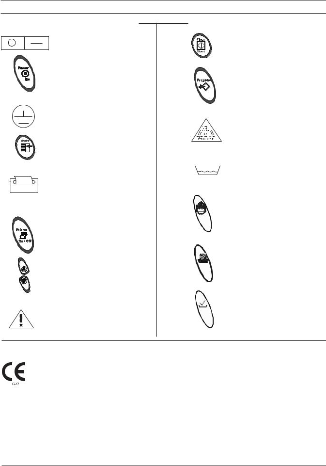
Table of Symbols
On/Off Power Switch
Power
Ground
Mode
Printer Connection
Printer On/Off
Arrows
Attention: Printer Connection Only
Clear/Start
Program
Hot Surface
Low Water
Dry
Ready
Sterilize
The conformity of the quality management system is certified with Certificate No. 369CE, dated April 8, 1999 by:
AMTAC Certification Services, LTD
Norman Road, Broadheath, Altrincham
Cheshire WA 14 4EP, United Kingdom
The identification number of the notified body for implementation of the procedure set out in Annex V of the Directive is 0473. The authorized representative :
Medical Device & QA Services
76, Stockport Road
Timperley
Cheshire
WA15 7SN
United Kingdom
2
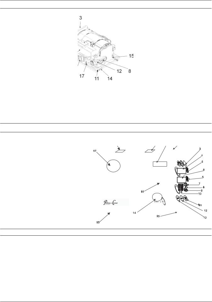
Visual Index
1Casing with Plumbing Diagram (inside cover)
2Fill
3Front Frame
4Door with Lock
5Drain
(quick connection behind door)
6Front Panel Microprocessor MPU
7Power PCB
8RTD (Steam) Sensor
9Reservoir with Overflow Vent
10Water Level Switch (inside reservoir)
11Printer Jack
12Solenoids
13Drying Pump
14Master Power Switch
15Heating Element
(mounted on bottom of chamber)
16Safety Valve
17Filter
18Transformer
Operating Features
1.Power Switch/Circuit Breaker (rear of unit)
2.Reservoir Fill
3.Operation Indicator Light
4. Display Window (Pressure) kPa
5. Arrow Switches
6. Display Window (Temp/Time) C/F / Minutes
7. Clear/Start Switch
8. Low Water Light
9. Mode Selection Switch
10. Mode/Program Display
11. Power On Switch
12. Programming Switch
13. Printer On/Off Switch
14. Quick Drain Connection (inside door)
15. Leveling Feet
16. Door Lock
17. Safety Valve (rear corner of unit)
18. Operating Instructions Label
19. Caution Label
20. Serial Number Plate (inside door)
Safety Features
The design of the autoclave has these safety features for your protection:
Door Lock
Door can be opened only when internal pressure is at atmospheric pressure.
Vent Valve
The vent valve will open and the P-2 alarm will display should the chamber pressure exceed 240 kPa.
Safety Valve
The safety valve opens as backup protection should the chamber pressure exceed 262 kPa.
Overheat Protection
Chamber temperature is protected with a surface sensor so the temperature will not exceed 159°C. It has additional overheat protection should the temperature of the heating elements reach 180°C.
Electrical Power Interruption
In case of a power failure during the sterilization cycle, pressure in the chamber is automatically vented to the atmosphere and display is blank.
3
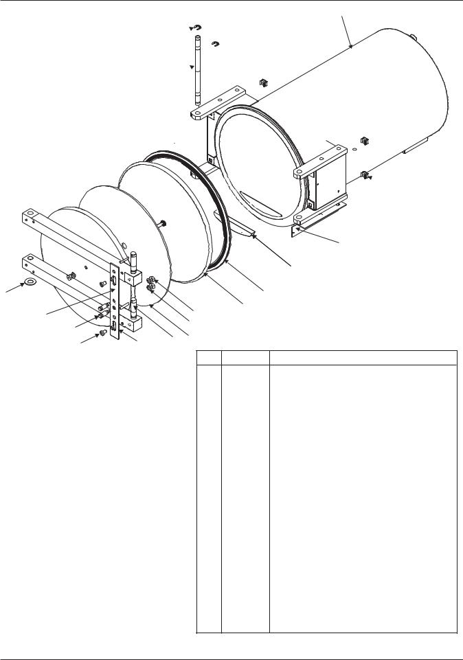
Chamber and Door |
7 |
6
5
 8
8
|
|
|
|
|
9 |
|
|
|
|
|
10 |
3 |
|
|
|
|
11 |
|
|
|
|
|
|
|
|
|
|
12 |
|
4 |
|
|
13 |
|
|
2 |
|
|
14 |
|
|
|
|
|
|
|
|
1 |
17 |
16 |
15 |
|
|
|
|
|
|||
|
|
|
|
||
|
|
|
No. |
Part No. |
Description |
|
|
|
1 |
15 39 845 |
ScrewButton Hd. 1/4 20 x .375" |
|
|
|
2 |
41 97 245 |
StudHandle |
|
|
|
3 |
01 97 54 |
WasherShim 1.0 oDX 15/32 IDX.016 |
|
|
|
4 |
15 39 258 |
Spacerlatch slide |
|
|
|
5 |
41 96 809 |
Hinge Pin |
|
|
|
6 |
15 39 589 |
E-Clip 3/8" |
|
|
|
7 |
41 97 112 |
Door & Chamber Assy. (8"- Model AE) |
|
|
|
|
41 97 179 |
Door & Chamber Assy. (10"- Model AF) |
|
|
|
8 |
30 00 077 |
NutRetainer |
|
|
|
9 |
42 05 790 |
BracketLever switch (8"- Model AE) |
|
|
|
|
42 05 808 |
BracketLever switch (10"- Model AF) |
|
|
|
10 |
33 22 281 |
SpacerDoor |
|
|
|
11 |
15 39 241 |
Seal (8"- Model AE) |
|
|
|
|
15 39 407 |
Seal (10"- Model AF) |
|
|
|
12 |
42 03 845 |
Gasket Retain Stud Assy. (8"- Model AE) |
|
|
|
|
42 03 985 |
Gasket Retain Stud Assy.(10"- Model AF) |
|
|
|
13 |
15 39 928 |
NutHex 41H 2520 |
|
|
|
14 |
15 39 894 |
Lock Washer- .26IDX.43ODX.05 STL |
|
|
|
15 |
15 39 514 |
InsulationDoor (8"- Model AE) |
|
|
|
|
15 39 720 |
InsulationDoor (10"- Model AF) |
|
|
|
16 |
54 69 635 |
Locking Pin8x10 |
|
|
|
17 |
51 74 870 |
SlideBar (8"- Model AE) |
|
|
|
|
51 74 888 |
SlideBar (10"- Model AF) |
4
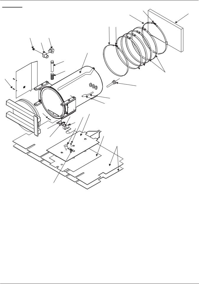
Chamber, Heating Element And Insulation
3
2 |
1 |
2 3
22 24
23
11
25
26  4
4
18
19
20
17
21
15 |
6 |
|
13 8
12
5
16
10
14
7
9
No. |
Part No. |
Description |
No. |
Part No. |
Description |
1 |
15 39 670 |
InsulationRear |
15 |
15 39 969 |
Phillips Hd. Screw- 4-40 x 1" |
2 |
30 05 035 |
StrapInsulation |
16 |
15 39 712 |
SpacerDoor Switch |
3 |
15 39 472 |
Spring |
17 |
18 81 023 |
TubeChamber |
4 |
15 39 647 |
BandPressure Plate |
18 |
30 00 036 |
Round Head Screw- 8-32 x .375 |
5 |
15 21 512 |
Overheat ProtectorChamber |
19 |
41 96 767 |
Compression SleevePressure Plate |
6 |
41 91 826 |
Heater (8"-Model AE) |
20 |
41 96 759 |
Compression Nut- 1/4" |
|
019769 |
Heater (10"-Model AF) |
21 |
18 81 031 |
FilterFill Line |
7 |
54 27 906 |
InsulationChamber |
22 |
42 07 432 |
1/4" Brass Plug |
8 |
33 25 094 |
Surface Sensor |
|
|
(Siemens 115, 230V & TUV 230V) |
9 |
15 31 628 |
Sensor Bracket |
23.1 |
42 07 424 |
Elbow- 1/2 St 1/4 Tap |
10 |
15 21 158 |
PlatePressure |
|
|
(Siemens 115, 230V & TUV 230V) |
11 |
42 00 346 |
TubeChamber Top |
23.2 |
15 39 324 |
Elbow- 1/2 St (Delta-XL 115V) |
12 |
15 39 803 |
NutHex 41H-440 |
24 |
42 05 055 |
ValueSafety Relief/Chain |
13 |
42 05 816 |
CoverLevel Switch |
25 |
15 36 486 |
Nipple- 1/2 NTPx4 |
14 |
42 05 782 |
Switch Lever |
26 |
15 29 267 |
TubeRelief |
5

Reservoir Parts
10
7
4
3  5
5
21
2
24
25
13
23
12 |
8 |
|
11
9
12
15 16
17
18
22
19
6 
14
1
20
No. |
Part No. |
Description |
No. |
Part No. |
Description |
|
1 |
33 39 913 |
Reservoir |
13 |
41 97 047 |
Tube - Chamber/Dump (8"-Model AE) |
|
2 |
41 96 924 |
Tube - Bel to Res (8"-Model AE) |
|
41 97 039 |
Tube - Chamber/Dump (10"-Model AF) |
|
|
41 96 999 |
Tube - Bel to Res (10"-Model AF) |
14 |
15 39 563 |
Washer - Rubber |
|
3 |
18 81 056 |
Nut - Compression (5/16") |
15 |
18 81 080 |
Nut - Condenser Tube |
|
4 |
18 81 064 |
Sleeve - Compression, Tapered |
16 |
18 81 098 |
Sleeve - Compression |
|
5 |
15 39 449 |
Coupling - Vent Condenser |
17 |
18 81 106 |
Condenser - 4 Coil |
|
6 |
18 81 072 |
O-ring |
|
18 |
94 32 311 |
Filter - Reservoir |
7 |
33 25 052 |
Water Level Assembly |
19 |
15 26 412 |
Nut - Air Valve |
|
8 |
30 00 002 |
Washer - Flat |
20 |
41 96 932 |
Tube - Reservoir to Fill (8"-Model AE) |
|
9 |
15 39 613 |
Nut - Air Valve |
|
41 96 965 |
Tube - Reservoir to Fill (10"-Model AF) |
|
10 |
42 05 899 |
Tube- |
Dump to Res (8"-Model AE) |
21 |
15 35 587 |
Gasket - Support |
|
41 97 021 |
Tube- |
Dump to Res (10"-Model AF) |
22 |
94 35 546 |
O-ring |
11 |
94 42 930 |
Dump Solenoid |
23 |
15 39 746 |
Cap Reservoir |
|
12 |
94 42 724 |
Connector |
24 |
41 96 841 |
Reducer |
|
|
|
|
|
25 |
94 42 732 |
Tee-- Compession 5/16 |
|
|
|
|
|
|
|
|
|
|
|
|
|
|
6
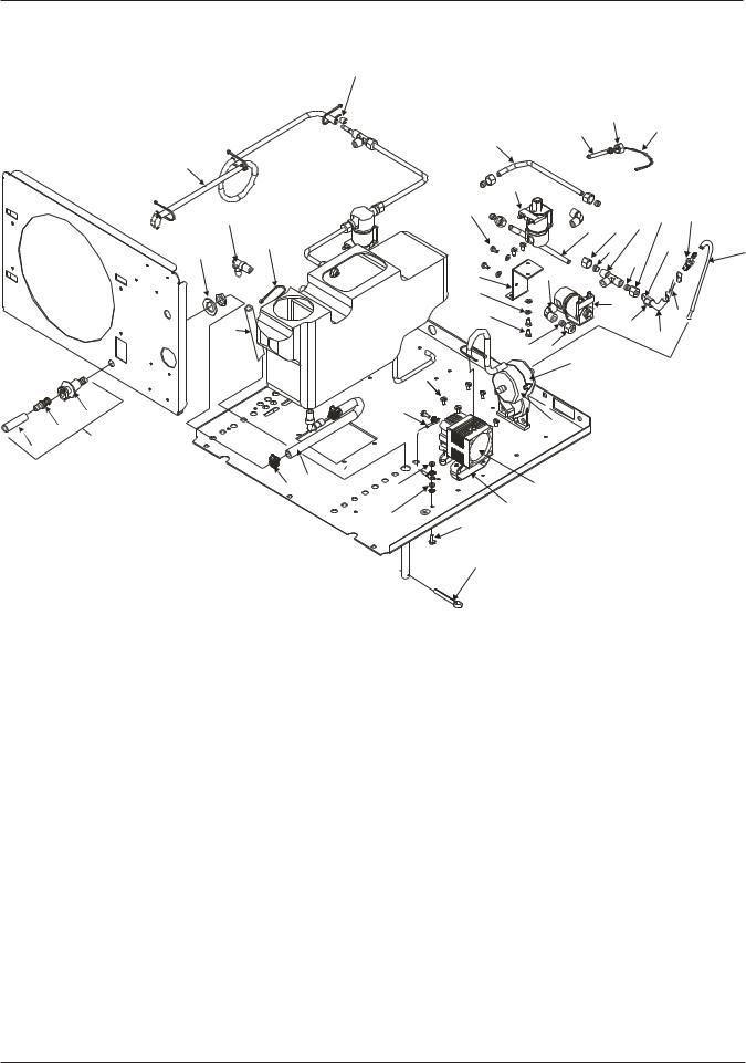
Plumbing Parts
|
|
42 |
|
|
|
|
|
|
|
|
35 |
|
|
|
|
|
33 |
|
36 |
|
|
|
|
|
|
|
|
|
|
32 |
|
|
|
|
|
34 |
|
|
|
|
|
|
|
31 |
|
|
|
|
|
|
21 |
|
|
|
38 |
|
6 |
|
|
|
24 |
|
|
|
|
|
|
||
|
|
|
|
37 |
|
|
|
|
|
5 |
24 |
|
|
|
7 |
|
|
25 |
30 |
21 |
|
4 |
|
|
|||
|
|
|
|
25 |
|
|
|
|
|
|
|
|
|
|
|
22 |
26 |
|
|
|
|
|
27 |
|
|
|
|
|
|
|
|
28 |
|
|
|
|
23 |
|
40 |
39 |
|
|
|
|
|
|
||
|
|
|
|
|
|
|
|
8 |
|
|
41 |
29 |
|
|
|
|
|
|
|
|
|
|
25 |
24 |
|
|
|
|
|
|
13 |
|
|
|
|
|
18 |
|
|
|
|
4 |
|
19 |
|
|
|
|
|
|
20 |
|
|
|
|
3 |
|
|
|
|
|
|
|
|
|
|
|
|
|
1 |
|
|
|
|
|
|
2 |
|
|
|
|
|
|
|
|
9 |
17.1 |
|
|
|
|
10 |
15 |
|
|
|
|
|
|
|
|
|
||
|
|
17.2 |
|
|
|
|
|
|
|
|
|
|
|
|
|
16 |
|
|
|
|
|
|
14 |
|
|
|
|
|
|
12 |
|
|
|
|
|
|
11 |
|
|
|
|
No. |
Part No. |
Description |
No. |
Part No. |
Description |
1 |
41 93 376 |
Drain Hose Assy. (Incl. 2,3,4) |
22 |
41 96 817 |
Bracket Valve |
2 |
33 39 947 |
Tube Drain |
23 |
30 00 044 |
Screw |
3 |
15 22 502 |
Quick Connect Male |
24 |
18 81 056 |
Nut |
4 |
15 22 494 |
Quick Connect Female |
25 |
18 81 064 |
Sleeve |
5 |
41 96 973 |
Tube Fill to Ch |
26 |
94 42 740 |
Elbow |
6 |
15 39 381 |
Elbow-White Polypropylene |
27 |
15 39 837 |
Washer |
7 |
15 39 274 |
Wire Tie |
28 |
94 42 922 |
Fill Solenoid |
8 |
94 42 906 |
Hose Overflow |
29 |
54 40 610 |
Elbow-900 5/16 x 1/8 Npt |
9 |
15 22 510 |
Hose Drain |
30 |
54 40 602 |
Tube-1" Long x 5/16 O.D. x .049w Brs |
10 |
15 39 365 |
Clamp - Hose |
31 |
94 42 948 |
Bellows Solenoid |
11 |
94 42 815 |
Pin Cotter |
32 |
41 96 981 |
Tube Bel to Ch |
12 |
15 39 829 |
Ground Screw- 10-24 x .5 |
33 |
041572 |
RTD Sensor |
13 |
41 97 146 |
Air Filter |
34 |
94 48 598 |
Tubing Connector - Long |
14 |
30 00 051 |
Lock Washer |
35 |
41 96 759 |
Nut 1/4 Comp. |
15 |
30 00 028 |
Hex Nut |
36 |
41 96 767 |
Sleeve 1/4 Comp. |
16 |
42 07 416 |
Pump Strap |
37 |
94 42 732 |
Tee-Compression 5/16" |
17.1 |
33 25 086 |
Pump (Delta & Siemens 115V) |
38 |
54 40 628 |
Barb-3/16 x 1/8 Npt |
17.2 |
33 38 683 |
Pump (Siemens & TUV 230V) |
39 |
54 73 017 |
Check Valve |
18 |
42 05 923 |
Screw Button Head |
40 |
18 81 056 |
Compression Nut 5/16" |
19 |
42 05 915 |
GND Wire Pump |
41 |
18 81 064 |
Compression Sleeve 5/16" |
20 |
41 97 138 |
Holder-Filter |
42 |
044176 |
Clamp |
21 |
94 48 598 |
Tubing Connector-Short |
|
|
|
|
|
|
|
|
|
7
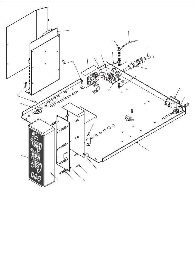
Electrical Parts
 3
3
1 |
21 |
12
9
20
5
4 19
14 |
6 |
|
8
7
10
22
14 |
11 |
|
18
14
16
23
13
15
24 2 17
|
No. |
Part No. |
Description |
No. |
Part No. |
Description |
|
|
1 |
044201 |
Power Supply PCB Assy |
13 |
045835 |
Control PCB Guard |
|
|
2 |
94 42 765 |
ExtensionSpacer Circuit Board |
14 |
42 05 923 |
ScrewButton Head |
|
|
3 |
41 97 005 |
Power PCB Guard |
15 |
15 25 331 |
Screw Pan Hd - 32 x 5/16" |
|
|
4 |
15 28 368 |
Transformer |
16 |
045841 |
PanelBottom (8"- Model AE) |
|
|
5 |
70 38 623 |
Terminal Block |
|
045455 |
PanelBottom (10"- Model AF) |
|
|
6 |
30 00 051 |
Lock Washer |
17 |
42 05 881 |
MPU Control Assy. (8"- Model AE) |
|
|
7 |
15 39 829 |
Ground Screw- 10-24 x .5 |
|
041136 |
MPU Control Assy. (10"- Model AF) |
|
|
8 |
77 40 640 |
Strain Relief |
18 |
18 98 639 |
ClipWire Harness |
|
|
9 |
15 30 661 |
Power Cord (115V) |
19 |
94 33 756 |
Heat Shrink Tubing |
|
|
|
041277 |
Power Cord ( 230V) |
20 |
33 25 029 |
CableAC Power to Pwr PCB |
|
|
10 |
46 99 190 |
Circuit Breaker - 10A (230V) |
21 |
42 07 390 |
Ground WireTerminal To Chasis |
|
|
|
46 92 208 |
Circuit Breaker - 20A (115V) |
22 |
29 44 098 |
LabelTeminal Block |
|
|
11 |
33 25 110 |
CablePrinter Socket |
23 |
040788 |
Front Panel PCB Assy. |
|
|
12 |
30 00 028 |
NutHex 41 H-1024 |
24 |
045487 |
Electrical Cover |
|
|
|
|
|
|
|
|
|
8
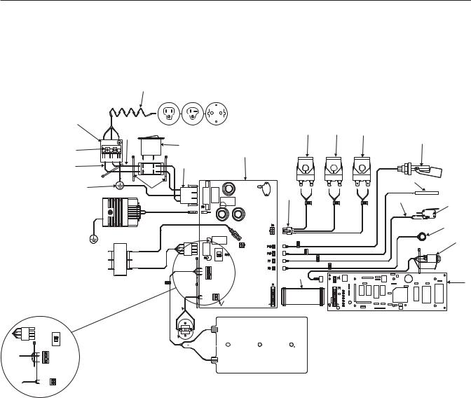
Electrical Diagram
|
9 |
|
|
|
7 |
|
|
|
|
|
|
14 |
15 |
16 |
|
8 |
|
|
17 |
|
|
10 |
|
|
|
TOP |
|
|
|
6 |
SIDE |
|
|
|
|
12 |
|
|
|
|
|
|
|
|
4 |
|
11 |
|
|
|
|
|
|
|
|
|
|
|
18 |
|
3 |
|
|
|
|
5 |
RED |
YELLOW |
BLACK |
|
|
13 |
|
20 |
|
|
|
|
19
P4
21
2
1
22
|
|
P7 |
WH |
1 |
|
BK |
2 |
|
WH |
3 |
24 |
|
4 |
|
TB1 |
|
23 |
TB2
27 
 25
25
26 
230V
|
No. |
Part No. |
Description |
No. |
Part No. |
Description |
|
|
|
1 |
15 28 368 |
Transformer 120/240V, 40VCT |
14 |
94 42 930 |
Dump Solenoid |
|
|
|
2 |
40 05 915 |
GND Wire to Pump TO Chasis |
15 |
94 42 948 |
Bellow Solenoid |
|
|
|
3 |
42 07 390 |
GND Wire Term to Chasis |
16 |
94 42 922 |
Fill Solenoid |
|
|
|
4 |
42 07 374 |
Wire Blu (Trm Blck/Crct Brk) |
17 |
33 25 052 |
Level Switch |
|
|
|
5 |
15 39 274 |
Wire Tie High Temp. |
18 |
041572 |
RTD Sensor |
|
|
|
6 |
70 38 623 |
Terminal Block |
19 |
42 05 782 |
Switch Lever |
|
|
|
7 |
29 44 098 |
Label Terminal Block |
20 |
33 25 078 |
Cable Door Switch |
|
|
|
8 |
42 07 382 |
Wire Brn (Trm Blck/Crct Brk) |
21 |
33 25 094 |
Surface Sensor |
|
|
|
9 |
15 30 661 |
Power Cord 115V) |
22 |
33 25 110 |
Cable Printer Socket |
|
|
|
|
041277 |
Power Cord ( 230V) |
23 |
42 05 881 |
MPU Control Assy. (8"- Model AE) |
|
|
|
10 |
46 99 208 |
Circuit Breaker - 20 AMP (230V) |
|
041136 |
MPU Control Assy. (10"- Model AF) |
|
|
|
|
46 99 190 |
Circuit Breaker - 10 AMP (115V) |
24 |
15 37 492 |
Cable AssyPower PCB to MPU |
|
|
|
11 |
15 37 476 |
Cable AC Power to Power PCB |
25 |
41 91 818 |
Heater (8"- Model AE) |
|
|
|
12 |
15 22 775 |
Power Supply PCB Assy |
|
019769 |
Heater (10"- Model AF) |
|
|
|
13 |
33 25 060 |
Cable Solenoid |
26 |
15 21 512 |
Chamber Overheat Protector |
|
|
|
|
|
|
27 |
33 25 037 |
Wire Assy Over Heat Protector |
|
|
|
|
|
|
|
|
|
|
|
|
|
|
|
|
|
|
|
|
9
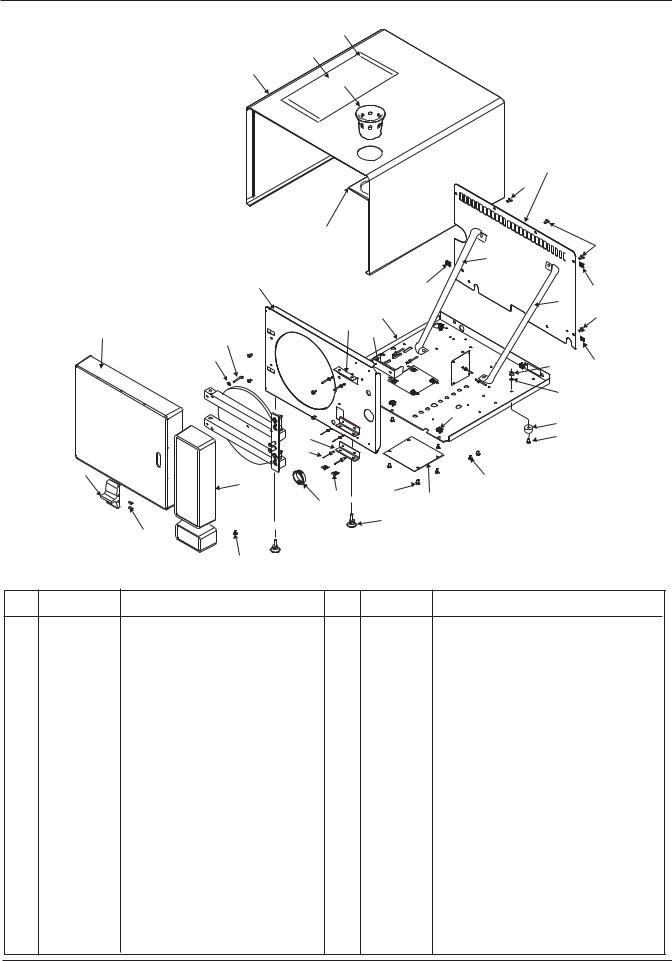
Front Frame and Casing Parts
2
34
3
1
|
|
|
|
|
|
4 |
|
|
|
|
|
|
|
26 |
|
|
|
6 |
|
|
|
|
|
|
|
|
|
|
|
|
26 |
|
|
|
|
|
|
33 |
|
|
|
7 |
|
25 |
|
|
25 |
|
|
|
|
|
|
|
|
|
|
|
|
|
|
32 |
|
|
|
|
|
5 |
|
|
26 |
|
|
|
|
|
|
|
|
|
|
|
22 |
|
|
|
|
|
8 |
|
|
23 |
|
|
|
|
|
21 |
|
|
|
|
|
|
|
20 |
|
|
|
|
|
|
|
|
|
|
|
29 |
25 |
|
|
|
|
|
|
30 |
|
|
|
|
|
|
19 |
28 |
|
|
|
|
|
|
|
|
|
|
|
15 |
|
|
|
27 |
|
|
|
|
|
|
|
|
|
|
|
16 |
|
|
|
|
|
|
9 |
|
|
|
|
18 |
|
|
|
12 |
|
|
|
|
|
|
|
|
17 |
|
|
|
|
|
|
|
14 |
|
|
|
|
|
|
|
24 |
|
|
|
|
|
|
13 |
|
|
|
|
|
|
|
|
|
|
|
|
|
|
|
|
|
31 |
|
|
|
|
|
10 |
|
|
|
|
|
|
|
11 |
|
|
|
|
|
No. |
Part No. |
Description |
No. |
Part No. |
Description |
|
|
1 |
18 81 114 |
Cup Reservoir Fill |
16 |
15 36 445 |
|
Rivet - Pop 8 CSNK 1/2 x .101/.130 |
|
2 |
51 49 815 |
Dou. Side Tape |
17 |
30 00 036 |
|
Phil. Hd. Screw- 8-32 x .375 ZN |
|
3 |
045840DW |
Case (8"- Model AE) |
18 |
15 39 902 |
|
Screw- 85SS-1024-37 |
|
|
045457DW |
Case (10"- Model AF) |
19 |
30 00 077 |
|
NutRetainer |
|
4 |
045843DW |
PanelRear (8"- Model AE) |
20 |
15 39 852 |
|
Lock Washer |
|
|
045456DW |
PanelRear (10"- Model AF) |
21 |
30 00 069 |
|
ScrewMach. Rd. Hd. 8-32 x 1.25 |
|
5 |
045841 |
Bottom Panel (8"- Model AE) |
22 |
15 39 183 |
|
BracketTop Electronic Cover |
|
|
045455 |
Bottom Panel (10"- Model AF) |
23 |
42 00 338 |
|
Reservoir Support |
|
6 |
42 05 048 |
Casing Gasket Set |
24 |
045459 |
|
CoverBottom |
|
7 |
045842 |
Front Panel (8"- Model AE) |
25 |
15 39 530 |
|
ClipSpeed |
|
|
045454 |
Front Panel (10"- Model AF) |
26 |
15 39 936 |
|
Mach. Slotted Screw- 10-24 x .375 |
|
8 |
51 63 550DW |
Door Cover (8"- Model AE) |
27 |
15 39 910 |
|
Mach. Slotted Scew- #10 |
|
|
51 63 535DW |
Door Cover (10"- Model AF) |
28 |
15 39 308 |
|
Foot |
|
9 |
045488 |
HandleGranite |
29 |
30 00 028 |
|
NutHex |
|
10 |
30 00 010 |
ScrewSoc. Hd. 6-32 x .375 |
30 |
15 39 811 |
|
Washer- 8 O.D. 2143 046 |
|
11 |
15 39 985 |
Cap- 8-32 x .375 |
31 |
4206459 |
|
GlideAdjustable Swivel |
|
12 |
045487 |
CoverElect Assy. |
32 |
045844 |
|
BraceRight (8"- Model AE) |
|
13 |
15 39 423 |
Bushing- 1 5/16 ID |
|
045464 |
|
BraceRight (10"- Model AF) |
|
14 |
15 39 316 |
NutSpeed |
33 |
045845 |
|
BraceLeft (8"- Model AE) |
|
15 |
15 39 571 |
BracketBottom Electronic Cover |
|
045465 |
|
BraceLeft (10"- Model AF) |
|
|
|
|
34 |
042912 |
|
Operation Quick Reference Card |
|
10

Tray and Tray Rest (8"- Model AE)
1
9
4
8
2
3
7
5
6
No. |
Part No. |
Description |
1 |
30 00 143 |
Tray Rest (Delta 115V & TUV 230V) |
2 |
15 39 290 |
Tray Rest (230V) |
3 |
15 33 848 |
Clip-Tray Support |
4 |
30 00 150 |
BaffleChamber (Delta 115V & TUV 230V) |
5 |
15 39 548 |
BaffleExport (230V) |
6 |
15 39 696 |
Tray Handling Accessory |
7 |
15 39 779 |
TrayExport |
8 |
15 39 761 |
TrayLarge Auto |
9 |
30 00 135 |
TraySmall Auto |
11

Tray and Tray Rest (10"- Model AF)
1
2
3
4
5
6
No. |
Part No. |
Description |
1 |
15 39 340 |
Large Instrument Tray |
2 |
15 39 357 |
Small Instrument Tray |
3 |
044159 |
Trayrest |
4 |
30 00 184 |
Trayrest - Export |
5 |
15 37 666 |
ClipTray Support |
6 |
30 00 192 |
Splash GuardExport |
|
|
|
12

Time/Temperature Printer
Printer Kit54 37 590 (120V)
Printer Kit54 37 624 (240V)
3
1
2
No. |
Part No. |
Description |
1 |
54 37 525 |
Printer |
2 |
54 39 166 |
Power Adapter - 115V |
|
54 75 533 |
Power Adapter - 230V |
3 |
54 30 595 |
Cable - Printer Jack |
|
|
|
13

Important Notes
•Measurements
Instruments required
1.Digital multimeter model FLUKE 8000 A, or equivalent.
Accuracy: AC voltage +- 0.5% of reading plus 1 digit.
DC voltage +- 0.1% of reading plus 2 digits.
DC current +- 0.3% of reading plus 1 digit.
2.Testleads: Small needle point testleads are required when voltage measurements are performed at connectors which remain plugged.
Always switch the unit OFF before connect ing measuring instruments.
Select the correct type of current/voltage and set the measuring range according to the expected measured values.
Carry out continuity tests only with the unit switched OFF.
•Warm-up period & self-test
Do not press any buttons when switching ON! After switching ON, the unit runs a self-test for the unit electronics.
•Interference with electromedical devices by radio telephones
To guarantee the operational safety of electromedical devices, the operation of mobile radio telephones in the medical practice or hospital area is prohibited.
•Troubleshooting tree guidelines
Element, component identifier: Located at the top of each page.
Unplug X4 See Figure 22. At lead, |
No |
||
check continuity X4.A4 / X4.B4. Is |
|
||
|
|
||
|
|
||
continuity present? |
|
||
|
|
|
|
|
Yes |
|
|
|
|
|
|
Refers to designated pictoral on preceeding page.
•When using the troubleshooting trees and a connector is unplugged for continuity or
voltage measurements, the term:
“at lead” indicates that the measurement is to be performed on the cable or “lead” end.
“at board” indicates that the measurement is to be performed on the PCB connector.
•Resetting the unit
Turn the power off at the main Power Switch. Turn unit back on after 10 seconds..
•Replacing parts
Switch the unit OFF and unplug before replacing parts.
To protect electrostatic-sensitive devices (ESD) on PC-boards, observe the ESD guidelines. Avoid coming into contact with electronics components. As well as possible, handle PC boards only at the edge. Discharge yourself by touching a grounding point.
Transport PC boards only in the original transport bags!
Find article numbers required for ordering replacement parts in the List of Spare Parts documents, order number P/L 4702135 for the 8” unit or P/L 4702143 for the 10” unit.
The pictorial representations in the spare parts list offer valuable assistance for replacement of parts.
14

Removing/Reinstalling Cover
1.To remove cover, remove only the two bottom screws of rear panel.
2.Remove reservoir fill cup.
3.Slide cover to rear, then lift front of cover slightly to clear top of reservoir.
Note: When replacing cover, make sure lip of front panel engages in slot along all edges. Reinstall screws and reservoir fill cup.
15

The Sterilizer is a fully automatic autoclave, which allows an operator to select one of the four preset functions (Wrapped, Unwrapped, Packs and Liquids) and one user-programmable function (Special) for sterilization or disinfection. The microprocessor automatically selects the cycle time, temperature and pressure for the preset programs. See User Manual.
When the operator depresses the “CLEAR/START” button, the unit will display the selected mode’s parameters for four seconds and then fill the chamber with distilled water from the reservoir. When the filling period is complete, automatic activation of the heating elements builds temperature and pressure for the desired cycle.
As the temperature in the unit rises above 90o C., the microprocessor monitors the unit for saturated steam conditions and starts the air bleeding process via an electronic bellows function. If this process cannot be completed in seven minutes, then the unit automatically aborts the cycle and displays a flashing “FAIL” on the display to indicate possible blocked or defective bellows. See “FAIL” in the Troubleshooting section. The cycle is aborted at this point to avoid a possible overpressure condition.
At the point that saturated steam conditions are met, the unit will continuously build temperature and pressure to the minimum values of the mode selected. These values are:
134OC and 216 KPa for Wrapped and Unwrapped, 121OC and 115 KPa for Packs and Liquids.
For the Special mode, the values can be set to the operator’s preference. See User Manual.
Once sterilization parameters are achieved, if the pressure drops more than 4 KPa below the selected pressure, or if the temperature drops more than 1OC below the selected temperature, the countdown timer will stop until these parameters are again met. If the timer does not resume countdown within three minutes, the unit will automatically abort the cycle and display “FAIL” continuously. See “FAIL” in the Troubleshooting section.
After the cycle is complete and the chamber is vented, the drying cycle begins. Filtered ambient air is pumped through the chamber for a preset time. The time is set at the factory for 30 minutes, but can be changed from 0-99 minutes. See User Manual.
16

Error Code Explanations
1.H20- Insufficient water in sterilizing chamber.
2.Fail- a) Unit takes more than 45 minutes to reach operating temperature;
b)Door opened after “FILL”, display extinguishes;
c)Unit takes more than 7 minutes between 101o C. and 110o C.;
d)More than a 3 minute lapse in sterilize countdown due to leak causing more than 4 KPa
pressure or if pressure decrease.
3.Door- Door not fully closed during fill cycle.
4.P1- Pressure sensor out of calibration or not working.
5.P2- Unit reaches 241 KPa before displaying 135o C.
6.SS-1- Steam sensor is defective or autoclave is too cold (Under 10o C.).
7.SS-2- Surface sensor circuit open during self test.
8.SS-3- Steam sensor too hot (Over 140o C.).
9.LB- Low battery condition in front control panel.
10.U1- Transformer problem.
11.S1- Fill/ Vent solenoid coil or circuit open.
12.S2- Dump solenoid coil or circuit open.
13.S3- Bellows solenoid coil or circuit open.
17
 Loading...