

Page 1
QUICK START
Sarix® TI Series Fixed Thermal Camera
C1319M-A (8/12)
Page 2
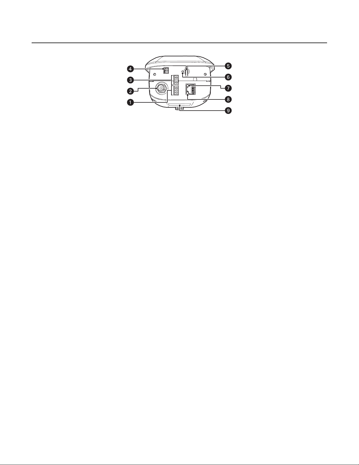
Product Overview
ì
Audio Connectors: Enables optional audio capability.
î
BNC Connector: Enables analog video output.
ï
Alarm and Relay Connectors: Enables optional alarms and relays.
ñ
24 VAC Connector: Provides power to the unit.
ó
Micro SD Card Slot: Saves a snapshot image to a micro SD card based on alarm activity.
NOTE: The micro SD card must be formatted as FAT32. Other formats are not compatible with the camera.
r
Reset Button: Reboots the camera or restores the camera’s factory default settings. This button is recessed. Using a small tool, such as
a paper clip, press and release the reset button once to reboot the camera. Press and hold the reset button for 10 seconds to restore the
camera to the factory default settings.
s
Ethernet Link LED: Flashes green to indicate that a live network connection is established.
Figure 1. Camera Features
t
Ethernet Activity LED: Glows solid green to indicate that data is being transmitted or received by the camera.
u
Product Label: Lists the model number, date code, serial number, and Media Access Control (MAC) address. This information might be
required for setup.
NOTE: Figure 1 shows the camera with the back cover removed.
2 C1319M-A (8/12)
Page 3
Installation
NOTE: For detailed instructions, refer to the installation/operation manual, which is available on the resource disc.
1. Mount the camera in the desired location using a recommended mount (refer to the instructions provided with the mount).
NOTE: Do not install the camera behind a window or other glass. Glass is opaque to long wave infrared and will block the camera's view.
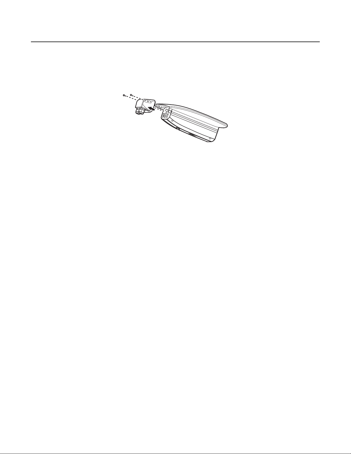
2. Loosen the two T20 security screws using a T20 security driver bit (supplied), and then remove the back cover.
3. Connect all wires and cables (refer to Figure 1 on page 2).
4. Optional: Connect the wiring for relays, alarms, and audio.
5. Turn on the system power.
NOTE: There might be a delay of approximately 3 minutes between power up and video being displayed in analog installations.
Figure 2. Removing the Back Cover
6. Refer to Operation on page 16 for instructions on how to use your Sarix TI system.
C1319M-A (8/12) 3
Page 4

Operation
Once the device is installed and power is applied, the device will start a configuration sequence: the green LED flashes five times per second for
approximately two minutes, indicating that the boot cycle is complete and the device is on line.
NOTE: If the device is not connected to a Dynamic Host Configuration Protocol (DHCP) server and DHCP is enabled, the configuration sequence
might take up to five minutes to complete.
IP ADDRESS SETTINGS
If the camera is connected to a Dynamic Host Configuration Protocol (DHCP) network and DHCP is set to the On position, the server will
automatically assign an IP address to the device; DHCP On is the default setting for the camera. Set DHCP to the Off position to set the camera’s
IP address manually.
NOTES:
• If the camera is not connected to a DHCP server but DHCP is set to On, the default IP address 192.168.0.20 on subnet mask 255.255.255.0
is automatically assigned to the camera. After the first camera is connected and assigned the default IP address, the system will
automatically look for other cameras on the auto IP address system and assign IP addresses in sequential order as required.
• For example, if three cameras are connected to a network without a DHCP server, the first camera is assigned address 192.168.0.20, the
second camera is assigned address 192.168.0.21, and the third camera is assigned address 192.168.0.22.
• Contact your network administrator to avoid network conflicts before setting/changing the camera’s IP address.
• If you do not know the camera’s IP address, install the Pelco Device Utility software available on the resource disc shipped with the product.
The utility will locate the assigned name, IP address, and MAC address for devices connected to the same virtual local area network (VLAN)
as your computer. The Device Utility software is also available at www.pelco.com/software/downloads/.
MINIMUM SYSTEM REQUIREMENTS
Network and processor bandwidth limitations might cause the video stream to pause or appear pixilated when additional Web-interface users
connect to the camera. Decrease the images per second (ips), resolution, compression, or bit rate settings of the Web interface video streams to
compensate for network/processor limitations.
Network Interface Card: 100 megabits (or greater)
Monitor: Minimum of 1024 x 768 resolution, 16- or 32-bit pixel color resolution
®
Web Browser: Internet Explorer
Media Player: Pelco Media Player or QuickTime
Mac OS X 10.4 (or later)
NOTES:
• Pelco Media Player is recommended for control, smoothness, and reduced latency as compared to QuickTime.
• This product is not compatible with QuickTime version 7.6.4 for Windows XP or Windows Vista. If you have this version installed on your PC,
you will need to upgrade to QuickTime version 7.6.5.
7.0 (or later) or Mozilla® Firefox® 3.0 (or later)
®
7.6.5 for Windows XP and Windows Vista, and Windows 7 or QuickTime 7.6.4 for
LOGGING ON TO THE CAMERA
1. Open the Web browser.
2. Type the camera’s IP address in the browser address bar.
NOTE: If you do not know the camera’s IP address, you can locate it using the Pelco Device Utility software.
3. Click the Login button in the navigation bar; a dialog box appears.
4. Type your user ID and password.
NOTE: If you are logging on to the camera as the administrator for the first time, the default User ID and Password are admin (all lowercase). For
security purposes, be sure to change the password after you log on for the first time.
5. Click Log In.
4 C1319M-A (8/12)
Page 5

LIVE VIDEO PAGE ICONS
Viewable icons are based on user permissions.
Select Stream: Selects the viewable video stream that is displayed in live view (primary or secondary) and selects unicast or multicast
settings.
Maximize Viewing Area: Scales the image to the full size of the browser. To resize the video pane to normal view, click the
Show Toolbar button in the upper-right corner of the window.
Show Toolbar: Returns the window to normal view. This option is only available after the window has been set to maximize the
viewing area.
Open Stream in New Window: Opens the video in a scalable, independent window. Opening the video in a separate window allows
you to view the video while other applications are running. This window can be minimized, maximized, or closed using the title bar
buttons of the active window. The window can also be resized by dragging the lower-right corner of the window.
Take a Snapshot: Captures the image displayed in the video pane and then saves it as a JPEG file.
Recalibrate Now: Immediately closes the shutter to improve video quality by removing noise from the image. During recalibration, the
video will freeze for approximately one-third of a second, and a small number of video frames will be lost.
Delay Recalibration: Delays closing the shutter by one minute.
SETTINGS PAGE
Depending on user permissions, the Settings page allows you to manage camera system settings, set up users, configure events, and control the
camera.
NOTE: The Settings menu might not be available if the user does not have permission to access this feature.
To access the camera settings:
1. Log on to the camera.
2. Click the Settings link in the navigation bar located in the upper-right corner of the page; a list of menu tabs appears.
3. Place the mouse pointer over a tab to display a list of submenus.
SYSTEM TAB
General Settings: Includes configurable fields for the device name, time server, and text overlay settings. You can also use the General Settings
page to configure the Simple Mail Transfer Protocol (SMTP) server to send an email notification when an event handler is activated.
Backup and Restore Settings: Once the camera settings have been configured for optimal scene display, use the backup feature to save the
camera settings. If the camera settings are changed and inadvertently result in a less desirable image, use the restore setting to restore the
camera to the previously saved settings.
System Information: Includes read-only fields for the firmware version, hardware version, model number, and serial number of the system. This
information is typically required by Pelco Product Support for troubleshooting purposes.
NETWORK TAB
General: Displays the hardware address, hostname, DHCP settings, and IP address settings.
SSL: Secure Socket Layers (SSL) encrypts communications making it difficult for unauthorized users to intercept and view user names and
passwords.
SSH: Secure Shell (SSH) allows Pelco Product Support to log on to and service the camera for advanced troubleshooting purposes.
802.1x: This standard authenticates devices that want to establish a point-to-point access through a wired or wireless port using Extensible
Authentication Protocol (EAP). This port-based authentication method prevents unauthorized access to a Local Area Network (LAN) through a
physical port.
SNMP: Simple Network Management Protocol (SNMP) manages TCP/IP-based networks from a single workstation or several workstations. The
camera supports SNMP versions 2c and 3 and can be configured to send data using a trap.
C1319M-A (8/12) 5
Page 6

IMAGING TAB
General imaging settings include adjustments for the thermal color palette, sharpness, image enhancement, and recalibration.
The color palette programs the specific range of colors to represent the temperatures in the thermal image. These colors are not calibrated to a
specific temperature; rather, they represent the temperature variations within the thermal image.
The sharpness setting sharpens details in a scene. The image enhancement setting adjusts the thermal contrast range and detail of the image
definition of objects in the image; a higher image enhancement setting results in higher contrast and greater image detail with increased noise.
The noise filtering setting adjusts the strength of the automatic noise filter; lower noise filtering results in greater image detail with more noise,
and higher noise filtering results in lower noise and image detail. It is recommended that you configure the image enhancement setting before
the noise filtering setting. Recalibration closes the shutter to improve video quality by removing noise from the image.
WARNINGS:
• When using the sharpness or image enhancement settings, be aware that picture noise, although unnoticeable to the eye, will
increase and may cause compression rate changes in DVRs, NVRs, and network devices.
• During recalibration, the video will freeze for approximately one-third of a second, and a small number of video frames will be lost.
A/V STREAMS TAB
Use the A/V Streams tab to configure the video and audio streams for the camera. The A/V Streams tab includes a Video Presets page, a Video
Configuration page, and an Audio Configuration page.
Video Presets: The Video Preset page includes three fully-configured video presets, which include primary and secondary video stream settings
for easy setup. These presets may also be used as a starting point for a custom video configuration. These preset configurations vary depending
on camera model.
Video Configuration: The Video Configuration page allows you to customize the compression, resolution, image rate, and bit rate of the video
streams. The default names for the streams are Primary Stream and Secondary Stream. Although each stream can be configured independently,
the settings of one stream can limit the options available to the other stream, depending on the processing power used.
NOTE: Always configure the primary stream before the secondary stream. The primary stream should always be the most resource-intensive of
the streams.
Audio Configuration: The Audio Configuration page allows you to setup the external audio device. The default setting for Audio is disabled,
which means that no audio is transmitted from the camera. When enabled, audio is transmitted from the camera to the PC. Based on your system
configuration, images and audio may not be synchronized.
NOTE: Improper use of audio/visual recording equipment may subject you to civil and criminal penalties. Applicable laws regarding the use of
such capabilities vary between jurisdictions and may require, among other things, express written consent from the recorded subjects. You are
solely responsible for insuring strict compliance with such laws and for strict adherence to any/all rights of privacy and personalty.
USERS TAB
General Settings: Changes the way the camera manages the users and groups settings. These settings can be managed on a camera-to-
camera basis or by using a centralized server to apply changes to multiple cameras. Use the general settings page to set the public user access
level.
This access level is a predefined set of user permissions that allow the camera to be accessed without logging on. The permission levels are
Operator, Viewer, and Disabled.
Users: Defines the permissions assigned to individuals logged on to the camera. Use this feature to create, modify, or delete user accounts.
EVENTS TAB
Sources: Defines the camera functions that are automatically triggered by an event source. The camera supports alarm, system, and timer event
sources.
Handlers: Defines the actions that a camera takes when an event occurs. The camera supports four event handlers: Send Email, Write JPEG to
SD Card, Upload JPEG to FTP Server, and Open/Close Relay.
Analytic Configuration: Allows you to create custom profiles that contain different camera settings. Pelco analytics can be configured and
enabled using a standard Web browser. The cameras are preloaded with several user-configurable behaviors, which are capable of running up to
three behaviors at the same time.
6 C1319M-A (8/12)
Page 7

PRODUCT WARRANTY AND RETURN INFORMATION
WARRANTY
Pelco will repair or replace, without charge, any merchandise proved defective in
material or workmanship for a period of one year after the date of shipment.
Exceptions to this warranty are as noted below:
• Five years:
– Fiber optic products
– Unshielded Twisted Pair (UTP) transmission products
– CC3701H-2, CC3701H-2X, CC3751H-2, CC3651H-2X, MC3651H-2, and
MC3651H-2X camera models
• Three years:
– FD Series and BU Series analog camera models
– Fixed network cameras and network dome cameras with Sarix
– Sarix thermal imaging products (TI and ESTI Series)
– Fixed analog camera models (C20 Series, CCC1390H Series, C10DN Series,
and C10CH Series)
– EH1500 Series enclosures
– Spectra
– Spectra HD dome products
– Camclosure
®
IV products (including Spectra IV IP)
®
IS Series integrated camera systems
– DX Series video recorders (except DX9000 Series which is covered for a
period of one year), DVR5100 Series digital video recorders, Digital Sentry
Series hardware products, DVX Series digital video recorders, and NVR300
Series network video recorders
®
– Endura
– Genex
Series distributed network-based video products
®
Series products (multiplexers, server, and keyboard)
– PMCL200/300/400 Series LCD monitors
– PMCL5xxF Series and PMCL5xxNB Series LCD monitors
• Two years:
– Standard varifocal, fixed focal, and motorized zoom lenses
– DF5/DF8 Series fixed dome products
®
– Legacy
– Spectra III
Series integrated positioning systems
™
, Spectra Mini, Spectra Mini IP, Esprit®, ExSite®, ExSite IP, and
PS20 scanners, including when used in continuous motion applications
– Esprit Ti and TI2500 Series thermal imaging products
– Esprit and WW5700 Series window wiper (excluding wiper blades)
– CM6700/CM6800/CM9700 Series matrix
– Digital Light Processing (DLP
®
) displays (except lamp and color wheel). The
lamp and color wheel will be covered for a period of 90 days. The air filter is
not covered under warranty.
®
technology
•Six months:
– All pan and tilts, scanners, or preset lenses used in continuous motion
applications (preset scan, tour, and auto scan modes)
Pelco will warrant all replacement parts and repairs for 90 days from the date of
Pelco shipment. All goods requiring warranty repair shall be sent freight prepaid
to a Pelco designated location. Repairs made necessary by reason of misuse,
alteration, normal wear, or accident are not covered under this warranty.
Pelco assumes no risk and shall be subject to no liability for damages or loss
resulting from the specific use or application made of the Products. Pelco’s liability
for any claim, whether based on breach of contract, negligence, infringement of
any rights of any party or product liability, relating to the Products shall not exceed
the price paid by the Dealer to Pelco for such Products. In no event will Pelco be
liable for any special, incidental, or consequential damages (including loss of use,
loss of profit, and claims of third parties) however caused, whether by the
negligence of Pelco or otherwise.
The above warranty provides the Dealer with specific legal rights. The Dealer may
also have additional rights, which are subject to variation from state to state.
If a warranty repair is required, the Dealer must contact Pelco at (800) 289-9100 or
(559) 292-1981 to obtain a Repair Authorization number (RA), and provide the
®
following information:
1. Model and serial number
2. Date of shipment, P.O. number, sales order number, or Pelco invoice number
3. Details of the defect or problem
If there is a dispute regarding the warranty of a product that does not fall under
the warranty conditions stated above, please include a written explanation with
the product when returned.
Method of return shipment shall be the same or equal to the method by which the
item was received by Pelco.
RETURNS
To expedite parts returned for repair or credit, please call Pelco at (800) 289-9100
or (559) 292-1981 to obtain an authorization number (CA number if returned for
credit, and RA number if returned for repair) and designated return location.
All merchandise returned for credit may be subject to a 20 percent restocking and
refurbishing charge.
Goods returned for repair or credit should be clearly identified with the assigned
CA or RA number and freight should be prepaid.
Revised 1-12-12
The materials used in the manufacture of this document and its components are compliant to the requirements of Directive 2002/95/EC.
This equipment contains electrical or electronic components that must be recycled properly to comply with Directive 2002/96/EC of the European Union
regarding the disposal of waste electrical and electronic equipment (WEEE). Contact your local dealer for procedures for recycling this equipment.
REVISION HISTORY
Manual # Date Comments
C1319M 9/11 Original version.
C1319M-A 8/11 Updated to include 640x480 models.
Pelco, the Pelco logo, and other trademarks associa ted with Pelco products referred to in this publication are trademarks of Pelco, Inc. or its affilia tes. © Copyright 2012, Pelco, Inc.
ONVIF and the ONVIF logo are trademarks of ONVIF Inc. All other product names and services are the property of their respective companies. All rights reserved.
Product specifications and availability are subject to change without notice.
Page 8

www.pelco.com
Pelco by Schneider Electric 3500 Pelco Way Clovis, California 93612-5699 United States
USA & Canada Tel (800) 289-9100 Fax (800) 289-9150
International Tel +1 (559) 292-1981 Fax +1 (559) 348-1120
 Loading...