

Page 1
®
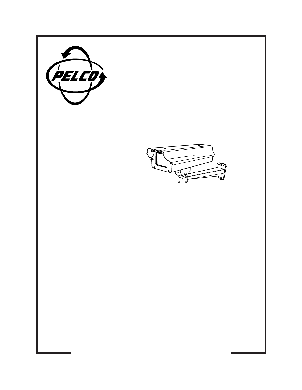
EU3512-3X
Environmental
Enclosure
and
Light Duty Wall Mount
Installation/
Operation Manual
C2428M-A (2/01)
Pelco • 3500 Pelco Way • Clovis, CA 93612-5699 USA • www.pelco.com
In North America and Canada: Tel (800) 289-9100 • FAX (800) 289-9150
International Customers: Tel +1(559) 292-1981 • FAX +1(559) 348-1120
Page 2

CONTENTS
LIST OF ILLUSTRATIONS
Section Page
IMPORTANT SAFEGUARDS AND WARNINGS ................................................................ 3
DESCRIPTION ................................................................................................................... 4
INSTALLATION...................................................................................................................4
INSTALL WALL MOUNT ............................................................................................ 4
ENCLOSURE INSTALLATION ...................................................................................4
CAMERA AND LENS INSTALLATION .......................................................................5
OPERATION ...................................................................................................................... 6
MAINTENANCE ................................................................................................................. 6
SPECIFICATIONS .............................................................................................................. 7
WARRANTY AND RETURN INFORMATION .................................................................... 8
Figure Page
1 Wiring Diagram .................................................................................................. 5
2 Enclosure Dimension Drawing ...........................................................................7
3 Mount Dimension Drawing .................................................................................7
LIST OF TABLES
Table Page
A Heater and Defroster Wiring Distances .............................................................. 5
B 24 VAC Wiring Distances ................................................................................... 6
C Video Coaxial Cable Wiring Distances...............................................................6
2 Pelco Manual C2428M-A (2/01)
Page 3
IMPORTANT SAFEGUARDS AND WARNINGS
Prior to installation and use of this product, the following WARNINGS should be observed.
1. Installation and servicing should only be done by qualified service personnel and
conform to all local codes.
2. Unless the unit is specifically marked as a NEMA Type 3, 3R, 3S, 4, 4X, 6 , or 6P
enclosure, it is designed for indoor use only and it must not be installed where exposed
to rain and moisture.
3. Only use replacement parts recommended by Pelco.
4. After replacement/repair of this unit’s electrical components, conduct a resistance
measurement between line and exposed parts to verify the exposed parts have not
been connected to line circuitry.
5. The installation method and materials should be capable of supporting four times the
weight of the enclosure, pan/tilt, camera and lens combination.
The product and/or manual may bear the following marks:
This symbol indicates that dangerous voltage constituting a risk of electric shock is
present within this unit.
This symbol indicates that there are important operating and maintenance instructions
in the literature accompanying this unit.
Please thoroughly familiarize yourself with the information in this manual prior to installation
and operation.
CAUTION:
RISK OF ELECTRIC SHOCK.
DO NOT OPEN.
Pelco Manual C2428M-A (2/01) 3
Page 4

DESCRIPTION
The EU3512-3X is an indoor/outdoor light-duty camera enclosure and light-duty wall mount.
The enclosure includes a sun shroud and 230 VAC heater and defroster. The wall mount has
an adjustable tilt table allowing for mechanical positioning of the enclosure.
Install the EU3512-3X to any wall or vertical surface, capable of supporting up to 20 pounds (9 kg).
INSTALLATION
INSTALL WALL MOUNT
Perform the following steps to install the mount:
1. Determine the mounting location. Use the flanged end of the mount as a template and
mark the fastener hole positions onto the mounting surface.
– Mounting to a solid surface mark the three fastener holes
– Mounting to a wall stud mark the two center fastener holes
2. Set the mount to the side and prepare the holes for the fasteners.
3. Position the mount over the mounting holes and secure with fasteners.
– Mounting to a solid surface, secure with three .25-inch diameter fasteners
– Mounting to a wall stud, secure with one .3125-inch fastener and one .25-inch
(not supplied)
fastener (not supplied)
If you install the mount outdoors, seal the fastener holes with an appropriate sealant to
prevent water damage. Apply the sealant between the mount and the mounting
surface.
ENCLOSURE INSTALLATION
1. Unlatch and open the lid of the enclosure.
2. Remove the camera sled from the rail of the enclosure.
a. Loosen the screws that hold the camera sled in place.
b. Slide the sled forward so it can be lifted out over the screws.
c. Remove the sled.
d. Remove the parts tied to the sled.
3. If you are wiring the enclosure with cable, remove the glands and nuts from the parts
bag and install them in the bottom of the enclosure. If you are wiring the enclosure
with conduit, do not install the glands.
4. Attach the base of the enclosure to the mount tilt table with the two 1/4-20 x .50-inch
screws (provided).
5. Loosen the cap nut located on the support bracket of the tilt table and adjust the tilt
table to the desired direction. Tighten the cap nut. Loosen the two screws on the tilt
table and adjust it for the desired angle. Tighten the screws.
4 Pelco Manual C2428M-A (2/01)
Page 5

CAMERA AND LENS INSTALLATION
1. To install the camera and lens onto the enclosure sled:
a. Extend the lens to the maximum length.
b. P osition the camera and lens so that they do not extend beyond the track.
c. Fasten the camera and lens to the sled with the two, 1/4-20 x .375 Phillips screws
supplied.
The edges of the sled are bent, one side up and the other side down. One side of the
sled has a wide lip and the other side has a narrow lip. In a typical installation, you
mount the camera so that the holes in the wide lip of the sled fit over the sled mounting screws. However, you can elevate the sled if you are installing a camera with a low
optical centerline or a camera with a large diameter lens. To elevate the sled, flip the
sled over so that the holes in the narrow lip of the sled fit over the sled mounting
screws.
2. Install the sled and camera assembly into the enclosure. Slide the sled over the
mounting screws and lightly tighten the screws.
3. Pull the power wires and cables through the glands or conduit into the enclosure.
Refer to Tables A and B to determine the size of the power wire to use. Refer to Table
C for the type of video coaxial cable to use.
4. Connect the cables for power and video to the camera.
5. Refer to Figure 1 to wire the heater and defroster to power.
6. If the camera lens is adjustable, extend the lens to its maximum length; verify that the
end of the lens is a minimum of .50-inch from the enclosure window.
7. Tighten the screws that secure the sled to the enclosure.
CAUTION:
When
using a single
power source for
both camera and accessories, consider the camera
power consumption when
determining the wire gauge.
Ta ble A does not include
camera power.
8. Adjust the glands for a tight fit around the cables.
9. Close the enclosure lid, and latch.
10. Adjust the camera focus and iris if necessary. If you need to adjust the focus and iris
manually, open the enclosure lid, adjust the focus and iris, and close the enclosure lid.
INPUT, AC HIGH
1
2
3
4
5
6
7
8
9
10
INPUT, AC LOW (NEUTRAL)
GROUND
DEFROSTER
HEATER
Figure 1. Wiring Diagram
Table A. Heater and Defroster Wiring Distances
The following cable sizes are the minimum recommended for use with the heater and defroster.
Input Power Cable Cable
Voltage Consumption Size Distance
230 VAC
at 50 Hz
13 watts 18 AWG (1.0 mm2) 31,890 ft (9,720 m)
20 AWG (0.5 mm2) 20,045 ft (6,109 m)
16 AWG (1.5 mm2) 50,612 ft (15,426 m)
2
14 AWG (2.5 mm
) 80,738 ft (24,608 m)
Pelco Manual C2428M-A (2/01) 5
Page 6

T ab le B. 24 VAC Wiring Distances
The following are the recommended maximum distances for 24 VAC applications and are
calculated with a 10-percent voltage drop. (Ten percent is generally the maximum allowable
voltage drop for AC-powered devices.)
Wire Gauge
EXAMPLE:
An enclosure
that requires 80 vA and is
installed 35 feet (10 m) from
the transformer would require a minimum wire gauge
of 20 Awg.
NOTE:
Distances are calculated in feet; values in parentheses are meters.
20 18 16 14 12 10
(0.5 mm2) (1.0 mm2) (1.5 mm2) (2.5 mm2) (4.0 mm2) (6.0 mm2)
10 283 451 716 1142 1811 2880
(86) (137) (218) (348) (551) (877)
20 141 225 358 571 905 1440
(42) (68) (109) (174) (275) (438)
30 94 150 238 380 603 960
(28) (45) (72) (115) (183) (292)
40 70 112 179 285 452 720
(21) (34) (54) (86) (137) (219)
50 56 90 143 228 362 576
(17) (27) (43) (69) (110) (175)
60 47 75 119 190 301 480
(14) (22) (36) (57) (91) (146)
70 40 64 102 163 258 411
Total vA consumed
(12) (19) (31) (49) (78) (125)
80 35 56 89 142 226 360
(10) (17) (27) (43) (68) (109)
90 31 50 79 126 201 320
(9) (15) (24) (38) (61) (97)
100 28 45 71 114 181 288
(8) (13) (21) (34) (55) (87)
T ab le C. Video Coaxial Cable Wiring Distances
Cable Type* Maximum Distance
RG59/U 750 ft (229 m)
RG6/U 1,000 ft (305 m)
RG11/U 1,500 ft (457 m)
Maximum distance from transformer to load
* Minimum cable requirements:
75 ohms impedance
All-copper center conductor
All-copper braided shield with 95% braid coverage
OPERATION
The enclosure has a thermostatically controlled heater, that is set to turn on at 50°F (10°C)
and turn off at 80°F (27°C). The defroster operates continuously.
MAINTENANCE
Regularly scheduled maintenance prolongs the operational life and appearance of the
equipment. Clean the window regularly with a soft cloth using a mild, nonabrasive detergent
and water to maintain picture clarity.
6 Pelco Manual C2428M-A (2/01)
Page 7

SPECIFICATIONS
ENCLOSURE
Camera Mounting: Multiple holes on adjustable camera sled; camera sled mounts in
Camera and
Lens Size: Accommodates camera and lens combinations (including BNC connector)
Viewing Window: Lexan®, .187-inch (4.75 mm) thick, optically clear, impact-resistant,
Viewing Area: 2.25 (H) x 2.63 (W) inches (5.71 x 6.68 cm)
Cable Entry: Two PG13.5 compression glands on the bottom of the enclosure;
Cable Entry Holes: .875-inch diameter; will accept 0.50-inch (1.27 cm) conduit fitting when
Latch: Link-lock, stainless steel, can be secured with padlock (not supplied).
GENERAL
Construction: Extruded and die-cast aluminum body
Dimensions: Refer to Figure 2
Ratings: EMA 4, IP 66
Environment: 10° to 120°F (-23° to 49°C)
Weight: 4 lb (1.75 kg)
MOUNT
Pan Adjustment: 360°
Tilt Adjustment: ± 75°
Construction
Mounting Arm: Die cast aluminum
Tilt Table and
Support Bracket: Aluminum
Finish: Gray polyester powder coat
Maximum Load: 20 lb (9 kg)
Dimensions: See Figure 3
Unit Weight: 2 lb (.91 kg)
Environment: Indoor/outdoor
threaded strip for easier removal and can be inverted for additional
camera elevation.
2.87 (W) x 3.00 (H) x 9.00 (L) inches (7.28 x 7.62 x 22.86 cm)
MR5 coated (U.L. 94HB rated).
maximum cable diameter 0.47-inch (1.19 cm).
compression gland is removed.
5.1
(13.0
3.8
(9.86
11.25
(28.57)
NOTE: VALUES IN PARENTHESES ARE CENTIMETERS;
ALL OTHERS ARE IN INCHES.
(Design and product specifications subject to change without notice.)
Ø .272 (.69), 3X
14.75
(37.47)
1.50
(3.81)
2.75
(6.99)
1.25
(3.18)
Ø .281 (7.13),
3X
2.86
(7.26)
3.48
(8.84)
Ø .343 (.87),
1X
NOTE: VALUES IN PARENTHESES ARE CENTIMETERS;
ALL OTHERS ARE IN INCHES.
10.53
(26.75)
12.75
(32.38)
(5.08
2.0
Figure 3. Mount Dimension DrawingFigure 2. Enclosure Dimension Drawing
3.28
(8.33)
11.08
(28.14)
1.64
(4.17)
1.40
(3.56)
2.00
(5.08)
2.80
(7.11)
2.95
(7.49)
5.43
(13.79)
Pelco Manual C2428M-A (2/01) 7
Page 8

PRODUCT WARRANTY AND RETURN INFORMATION
WARRANTY
Pelco will repair or replace, without charge, any merchandise proved defective in material or
workmanship for a period of one year after the date of shipment.
Exceptions to this warranty are as noted below:
• Five years on FT/FR8000 Series fiber optic products.
®
• Three years on Genex
• Three years on Camclosure® and fixed camera models, except the CC3701H-2,
CC3701H-2X, CC3751H-2, CC3651H-2X, MC3651H-2, and MC3651H-2X camera models,
which have a five-year warranty.
•Two years on standard motorized or fixed focal length lenses.
•Two years on Legacy
fixed dome products.
•Two years on Spectra
continuous motion applications.
•Two years on Esprit
• Eighteen months on DX Series digital video recorders, NVR300 Series network video
recorders, and Endura
• One year (except video heads) on video cassette recorders (VCRs). Video heads will be
covered for a period of six months.
• Six months on all pan and tilts, scanners or preset lenses used in continuous motion
applications (that is, preset scan, tour and auto scan modes).
Pelco will warrant all replacement parts and repairs for 90 days from the date of Pelco
shipment. All goods requiring warranty repair shall be sent freight prepaid to Pelco, Clovis,
California. Repairs made necessary by reason of misuse, alteration, normal wear, or accident
are not covered under this warranty.
Pelco assumes no risk and shall be subject to no liability for damages or loss resulting from
the specific use or application made of the Products. Pelco’s liability for any claim, whether
based on breach of contract, negligence, infringement of any rights of any party or product
liability, relating to the Products shall not exceed the price paid by the Dealer to Pelco for
such Products. In no event will Pelco be liable for any special, incidental or consequential
damages (including loss of use, loss of profit and claims of third parties) however caused,
whether by the negligence of Pelco or otherwise.
The above warranty provides the Dealer with specific legal rights. The Dealer may also have
additional rights, which are subject to variation from state to state.
Series products (multiplexers, server, and keyboard).
®
, CM6700/CM6800/CM9700 Series matrix, and DF5/DF8 Series
®
, Esprit®, ExSite™, and PS20 scanners, including when used in
®
and WW5700 Series window wiper (excluding wiper blades).
™
Series distributed network-based video products.
If a warranty repair is required, the Dealer must contact Pelco at (800) 289-9100 or
(559) 292-1981 to obtain a Repair Authorization number (RA), and provide the following
information:
1. Model and serial number
2. Date of shipment, P.O. number, Sales Order number, or Pelco invoice number
3. Details of the defect or problem
If there is a dispute regarding the warranty of a product which does not fall under the
warranty conditions stated above, please include a written explanation with the product
when returned.
Method of return shipment shall be the same or equal to the method by which the item was
received by Pelco.
RETURNS
In order to expedite parts returned to the factory for repair or credit, please call the factory at
(800) 289-9100 or (559) 292-1981 to obtain an authorization number (CA number if returned
for credit, and RA number if returned for repair).
All merchandise returned for credit may be subject to a 20% restocking and refurbishing
charge.
Goods returned for repair or credit should be clearly identified with the assigned CA or RA
number and freight should be prepaid. Ship to the appropriate address below.
If you are located within the continental U.S., Alaska, Hawaii or Puerto Rico, send goods to:
Service Department
Pelco
3500 Pelco Way
Clovis, CA 93612-5699
If you are located outside the continental U.S., Alaska, Hawaii or Puerto Rico and are
instructed to return goods to the USA, you may do one of the following:
If the goods are to be sent by a COURIER SERVICE, send the goods to:
Pelco
3500 Pelco Way
Clovis, CA 93612-5699 USA
If the goods are to be sent by a FREIGHT FORWARDER, send the goods to:
Pelco c/o Expeditors
473 Eccles Avenue
South San Francisco, CA 94080 USA
Phone: 650-737-1700
Fax: 650-737-0933
REVISION HISTORY
Manual # Date Comments
C2428M 01/01 Original version.
C2428M-A 2/01 Removed reference to 120 VAC.
Pelco, the Pelco logo, Camclosure, Esprit, Genex, Legacy, and Spectra are registered trademarks of Pelco. © Copyright 2001, Pelco.
Endura and ExSite are trademarks of Pelco. All rights reserved.
8 Pelco Manual C2428M-A (2/01)
 Loading...