

Page 1
Installation Manual
DX8000
Digital Video Recorder C623M-C (3/05)
Page 2

Protecting people and property in a million locations worldwide.
Page 3

Contents
Before You Begin . . . . . . . . . . . . . . . . . . . . . . . . . . . . . . . . . . . . . . . . . . . . . . . . . . . . . . . . . . . . . . . . . . . . . . . . . . . . . . . . . . . . . . . . . . . . . . . . . . . . .7
Additional Warnings and Cautions . . . . . . . . . . . . . . . . . . . . . . . . . . . . . . . . . . . . . . . . . . . . . . . . . . . . . . . . . . . . . . . . . . . . . . . . . . . . . . . . . . . . . . . .8
Regulatory Notices . . . . . . . . . . . . . . . . . . . . . . . . . . . . . . . . . . . . . . . . . . . . . . . . . . . . . . . . . . . . . . . . . . . . . . . . . . . . . . . . . . . . . . . . . . . . . . . . . . . .9
Description . . . . . . . . . . . . . . . . . . . . . . . . . . . . . . . . . . . . . . . . . . . . . . . . . . . . . . . . . . . . . . . . . . . . . . . . . . . . . . . . . . . . . . . . . . . . . . . . . . . . . . . . .10
Features . . . . . . . . . . . . . . . . . . . . . . . . . . . . . . . . . . . . . . . . . . . . . . . . . . . . . . . . . . . . . . . . . . . . . . . . . . . . . . . . . . . . . . . . . . . . . . . . . . . . . . .11
Models . . . . . . . . . . . . . . . . . . . . . . . . . . . . . . . . . . . . . . . . . . . . . . . . . . . . . . . . . . . . . . . . . . . . . . . . . . . . . . . . . . . . . . . . . . . . . . . . . . . . . . . .12
Optional Accessories . . . . . . . . . . . . . . . . . . . . . . . . . . . . . . . . . . . . . . . . . . . . . . . . . . . . . . . . . . . . . . . . . . . . . . . . . . . . . . . . . . . . . . . . . . . . .12
Parts List . . . . . . . . . . . . . . . . . . . . . . . . . . . . . . . . . . . . . . . . . . . . . . . . . . . . . . . . . . . . . . . . . . . . . . . . . . . . . . . . . . . . . . . . . . . . . . . . . . . . . . . . . . .13
Application Examples . . . . . . . . . . . . . . . . . . . . . . . . . . . . . . . . . . . . . . . . . . . . . . . . . . . . . . . . . . . . . . . . . . . . . . . . . . . . . . . . . . . . . . . . . . . . . . . . .14
Equipment Rack Mounting . . . . . . . . . . . . . . . . . . . . . . . . . . . . . . . . . . . . . . . . . . . . . . . . . . . . . . . . . . . . . . . . . . . . . . . . . . . . . . . . . . . . . . . . . . . . .15
Back Panel Layout . . . . . . . . . . . . . . . . . . . . . . . . . . . . . . . . . . . . . . . . . . . . . . . . . . . . . . . . . . . . . . . . . . . . . . . . . . . . . . . . . . . . . . . . . . . . . . . . . . . .17
Hardware Setup . . . . . . . . . . . . . . . . . . . . . . . . . . . . . . . . . . . . . . . . . . . . . . . . . . . . . . . . . . . . . . . . . . . . . . . . . . . . . . . . . . . . . . . . . . . . . . . . . . . . .18
Basic Connections . . . . . . . . . . . . . . . . . . . . . . . . . . . . . . . . . . . . . . . . . . . . . . . . . . . . . . . . . . . . . . . . . . . . . . . . . . . . . . . . . . . . . . . . . . . . . . .18
Network Setup . . . . . . . . . . . . . . . . . . . . . . . . . . . . . . . . . . . . . . . . . . . . . . . . . . . . . . . . . . . . . . . . . . . . . . . . . . . . . . . . . . . . . . . . . . . . . . . . . .19
RS-422/RS-485 Communication Port Setup . . . . . . . . . . . . . . . . . . . . . . . . . . . . . . . . . . . . . . . . . . . . . . . . . . . . . . . . . . . . . . . . . . . . . . . . . . .20
Alarm Input Installation . . . . . . . . . . . . . . . . . . . . . . . . . . . . . . . . . . . . . . . . . . . . . . . . . . . . . . . . . . . . . . . . . . . . . . . . . . . . . . . . . . . . . . . . . . .22
Relay Output Installation . . . . . . . . . . . . . . . . . . . . . . . . . . . . . . . . . . . . . . . . . . . . . . . . . . . . . . . . . . . . . . . . . . . . . . . . . . . . . . . . . . . . . . . . . .23
Software Setup . . . . . . . . . . . . . . . . . . . . . . . . . . . . . . . . . . . . . . . . . . . . . . . . . . . . . . . . . . . . . . . . . . . . . . . . . . . . . . . . . . . . . . . . . . . . . . . . . . . . . .24
Starting the Unit . . . . . . . . . . . . . . . . . . . . . . . . . . . . . . . . . . . . . . . . . . . . . . . . . . . . . . . . . . . . . . . . . . . . . . . . . . . . . . . . . . . . . . . . . . . . . . . .24
Logging in for the First Time . . . . . . . . . . . . . . . . . . . . . . . . . . . . . . . . . . . . . . . . . . . . . . . . . . . . . . . . . . . . . . . . . . . . . . . . . . . . . . . . . . . . . . .25
Shutting Down . . . . . . . . . . . . . . . . . . . . . . . . . . . . . . . . . . . . . . . . . . . . . . . . . . . . . . . . . . . . . . . . . . . . . . . . . . . . . . . . . . . . . . . . . . . . . . . . . .26
Exiting to Windows Operating System . . . . . . . . . . . . . . . . . . . . . . . . . . . . . . . . . . . . . . . . . . . . . . . . . . . . . . . . . . . . . . . . . . . . . . . . . . . . . . .27
Setting the System Language . . . . . . . . . . . . . . . . . . . . . . . . . . . . . . . . . . . . . . . . . . . . . . . . . . . . . . . . . . . . . . . . . . . . . . . . . . . . . . . . . . . . . .28
Configuring the Regional Setting in the Windows Operating System . . . . . . . . . . . . . . . . . . . . . . . . . . . . . . . . . . . . . . . . . . . . . . . . . . .28
Configuring the Language Setting of the DX8000 . . . . . . . . . . . . . . . . . . . . . . . . . . . . . . . . . . . . . . . . . . . . . . . . . . . . . . . . . . . . . . . . . .32
Setting the System Time . . . . . . . . . . . . . . . . . . . . . . . . . . . . . . . . . . . . . . . . . . . . . . . . . . . . . . . . . . . . . . . . . . . . . . . . . . . . . . . . . . . . . . . . . .33
Enabling and Using Ctrl+Alt+Del . . . . . . . . . . . . . . . . . . . . . . . . . . . . . . . . . . . . . . . . . . . . . . . . . . . . . . . . . . . . . . . . . . . . . . . . . . . . . . . . . . . .34
Using Ctrl+Alt+Del . . . . . . . . . . . . . . . . . . . . . . . . . . . . . . . . . . . . . . . . . . . . . . . . . . . . . . . . . . . . . . . . . . . . . . . . . . . . . . . . . . . . . . . . . .34
Network Software Configuration . . . . . . . . . . . . . . . . . . . . . . . . . . . . . . . . . . . . . . . . . . . . . . . . . . . . . . . . . . . . . . . . . . . . . . . . . . . . . . . . . . .35
DHCP Setup . . . . . . . . . . . . . . . . . . . . . . . . . . . . . . . . . . . . . . . . . . . . . . . . . . . . . . . . . . . . . . . . . . . . . . . . . . . . . . . . . . . . . . . . . . . . . . . .36
Static IP Setup . . . . . . . . . . . . . . . . . . . . . . . . . . . . . . . . . . . . . . . . . . . . . . . . . . . . . . . . . . . . . . . . . . . . . . . . . . . . . . . . . . . . . . . . . . . . .37
TCP/IP Port and Bandwidth Throttle Setup . . . . . . . . . . . . . . . . . . . . . . . . . . . . . . . . . . . . . . . . . . . . . . . . . . . . . . . . . . . . . . . . . . . . . . .38
Accessing Network Information . . . . . . . . . . . . . . . . . . . . . . . . . . . . . . . . . . . . . . . . . . . . . . . . . . . . . . . . . . . . . . . . . . . . . . . . . . . . . . . .40
DNS/WINS Setup . . . . . . . . . . . . . . . . . . . . . . . . . . . . . . . . . . . . . . . . . . . . . . . . . . . . . . . . . . . . . . . . . . . . . . . . . . . . . . . . . . . . . . . . . . .41
RS-422/RS-485 Communication Port Software Configuration . . . . . . . . . . . . . . . . . . . . . . . . . . . . . . . . . . . . . . . . . . . . . . . . . . . . . . . . . . . . .42
Client Software Setup . . . . . . . . . . . . . . . . . . . . . . . . . . . . . . . . . . . . . . . . . . . . . . . . . . . . . . . . . . . . . . . . . . . . . . . . . . . . . . . . . . . . . . . . . . . .44
Recommended System Requirements . . . . . . . . . . . . . . . . . . . . . . . . . . . . . . . . . . . . . . . . . . . . . . . . . . . . . . . . . . . . . . . . . . . . . . . . . . .44
Installing the PC Client Application . . . . . . . . . . . . . . . . . . . . . . . . . . . . . . . . . . . . . . . . . . . . . . . . . . . . . . . . . . . . . . . . . . . . . . . . . . . . .44
Enabling IPSec Security Services . . . . . . . . . . . . . . . . . . . . . . . . . . . . . . . . . . . . . . . . . . . . . . . . . . . . . . . . . . . . . . . . . . . . . . . . . . . . . . .47
Disabling IPSec Security Services . . . . . . . . . . . . . . . . . . . . . . . . . . . . . . . . . . . . . . . . . . . . . . . . . . . . . . . . . . . . . . . . . . . . . . . . . . . . . .47
Installing the Client Emergency Agent Application . . . . . . . . . . . . . . . . . . . . . . . . . . . . . . . . . . . . . . . . . . . . . . . . . . . . . . . . . . . . . . . . .48
Installing the DX8000 Viewer . . . . . . . . . . . . . . . . . . . . . . . . . . . . . . . . . . . . . . . . . . . . . . . . . . . . . . . . . . . . . . . . . . . . . . . . . . . . . . . . . .51
Installing the DX8000 Web Client . . . . . . . . . . . . . . . . . . . . . . . . . . . . . . . . . . . . . . . . . . . . . . . . . . . . . . . . . . . . . . . . . . . . . . . . . . . . . .52
Recommended System Requirements for Mobile (PDA) Client . . . . . . . . . . . . . . . . . . . . . . . . . . . . . . . . . . . . . . . . . . . . . . . . . . . . . . . .53
Installing the Mobile (PDA) Client application . . . . . . . . . . . . . . . . . . . . . . . . . . . . . . . . . . . . . . . . . . . . . . . . . . . . . . . . . . . . . . . . . . . . .54
Accessing the DX8000’s Electronic Documentation . . . . . . . . . . . . . . . . . . . . . . . . . . . . . . . . . . . . . . . . . . . . . . . . . . . . . . . . . . . . . . . . . . . . . . . . .56
Appendix A: Printer Setup . . . . . . . . . . . . . . . . . . . . . . . . . . . . . . . . . . . . . . . . . . . . . . . . . . . . . . . . . . . . . . . . . . . . . . . . . . . . . . . . . . . . . . . . . . . . .57
Printer Hardware Setup . . . . . . . . . . . . . . . . . . . . . . . . . . . . . . . . . . . . . . . . . . . . . . . . . . . . . . . . . . . . . . . . . . . . . . . . . . . . . . . . . . . . . . . . . . .57
Printer Software Setup . . . . . . . . . . . . . . . . . . . . . . . . . . . . . . . . . . . . . . . . . . . . . . . . . . . . . . . . . . . . . . . . . . . . . . . . . . . . . . . . . . . . . . . . . . .59
C623M-C (3/05) 3
Page 4

Setting Up a Local Plug-and-Play Printer . . . . . . . . . . . . . . . . . . . . . . . . . . . . . . . . . . . . . . . . . . . . . . . . . . . . . . . . . . . . . . . . . . . . . . . . .59
Setting Up a Local Printer that is Not Plug-and-Play . . . . . . . . . . . . . . . . . . . . . . . . . . . . . . . . . . . . . . . . . . . . . . . . . . . . . . . . . . . . . . . .62
Setting Up a Network Printer . . . . . . . . . . . . . . . . . . . . . . . . . . . . . . . . . . . . . . . . . . . . . . . . . . . . . . . . . . . . . . . . . . . . . . . . . . . . . . . . . .68
Appendix B: Connecting Optional DX8000-MUX8/16 Display Card . . . . . . . . . . . . . . . . . . . . . . . . . . . . . . . . . . . . . . . . . . . . . . . . . . . . . . . . . . . . . .72
Appendix C: Connecting the Optional DX8000-AUD Audio Option . . . . . . . . . . . . . . . . . . . . . . . . . . . . . . . . . . . . . . . . . . . . . . . . . . . . . . . . . . . . . .73
Setting Up Audio Inputs . . . . . . . . . . . . . . . . . . . . . . . . . . . . . . . . . . . . . . . . . . . . . . . . . . . . . . . . . . . . . . . . . . . . . . . . . . . . . . . . . . . . . . . . . . .73
Setting Up Audio Output . . . . . . . . . . . . . . . . . . . . . . . . . . . . . . . . . . . . . . . . . . . . . . . . . . . . . . . . . . . . . . . . . . . . . . . . . . . . . . . . . . . . . . . . . .75
Appendix D: Connecting an Uninterruptible Power Supply (UPS) . . . . . . . . . . . . . . . . . . . . . . . . . . . . . . . . . . . . . . . . . . . . . . . . . . . . . . . . . . . . . . .76
UPS to DVR Communication and Power Connections . . . . . . . . . . . . . . . . . . . . . . . . . . . . . . . . . . . . . . . . . . . . . . . . . . . . . . . . . . . . . . . . . . . .76
Software Setup for a USB Connected UPS Device . . . . . . . . . . . . . . . . . . . . . . . . . . . . . . . . . . . . . . . . . . . . . . . . . . . . . . . . . . . . . . . . . . . . . .77
Appendix E: External Storage Expansion Using DX9200HDDI . . . . . . . . . . . . . . . . . . . . . . . . . . . . . . . . . . . . . . . . . . . . . . . . . . . . . . . . . . . . . . . . . .80
Basic Installation . . . . . . . . . . . . . . . . . . . . . . . . . . . . . . . . . . . . . . . . . . . . . . . . . . . . . . . . . . . . . . . . . . . . . . . . . . . . . . . . . . . . . . . . . . . . . . . .80
Additional Hard Disk Installation . . . . . . . . . . . . . . . . . . . . . . . . . . . . . . . . . . . . . . . . . . . . . . . . . . . . . . . . . . . . . . . . . . . . . . . . . . . . . . . . . . . .81
Preparing the DX8000 to Access Newly Installed Drives . . . . . . . . . . . . . . . . . . . . . . . . . . . . . . . . . . . . . . . . . . . . . . . . . . . . . . . . . . . .81
Specifications . . . . . . . . . . . . . . . . . . . . . . . . . . . . . . . . . . . . . . . . . . . . . . . . . . . . . . . . . . . . . . . . . . . . . . . . . . . . . . . . . . . . . . . . . . . . . . . . . . . . . . .93
List of Tables
A Video Coaxial Cable Requirements . . . . . . . . . . . . . . . . . . . . . . . . . . . . . . . . . . . . . . . . . . . . . . . . . . . . . . . . . . . . . . . . . . . . . . . . . . . . . . . .18
B TCP/IP Ports Used by the DX8000 . . . . . . . . . . . . . . . . . . . . . . . . . . . . . . . . . . . . . . . . . . . . . . . . . . . . . . . . . . . . . . . . . . . . . . . . . . . . . . . . .38
C RS-422/RS-485 Port Settings. . . . . . . . . . . . . . . . . . . . . . . . . . . . . . . . . . . . . . . . . . . . . . . . . . . . . . . . . . . . . . . . . . . . . . . . . . . . . . . . . . . . .42
D DX8000 Manual Documents . . . . . . . . . . . . . . . . . . . . . . . . . . . . . . . . . . . . . . . . . . . . . . . . . . . . . . . . . . . . . . . . . . . . . . . . . . . . . . . . . . . . .56
4 C623M-C (3/05)
Page 5

List of Illustrations
1 System with Single DX8000. . . . . . . . . . . . . . . . . . . . . . . . . . . . . . . . . . . . . . . . . . . . . . . . . . . . . . . . . . . . . . . . . . . . . . . . . . . . . . . . . . . . . .14
2 System with Multiple DX8000s . . . . . . . . . . . . . . . . . . . . . . . . . . . . . . . . . . . . . . . . . . . . . . . . . . . . . . . . . . . . . . . . . . . . . . . . . . . . . . . . . . .14
3 System with Multiple DX8000s and Multiple Clients . . . . . . . . . . . . . . . . . . . . . . . . . . . . . . . . . . . . . . . . . . . . . . . . . . . . . . . . . . . . . . . . . .14
4 Remove Left and Right Side Plates . . . . . . . . . . . . . . . . . . . . . . . . . . . . . . . . . . . . . . . . . . . . . . . . . . . . . . . . . . . . . . . . . . . . . . . . . . . . . . . .15
5 Attaching Rack Ears and Handles . . . . . . . . . . . . . . . . . . . . . . . . . . . . . . . . . . . . . . . . . . . . . . . . . . . . . . . . . . . . . . . . . . . . . . . . . . . . . . . . .15
6 Rack Mount Installation . . . . . . . . . . . . . . . . . . . . . . . . . . . . . . . . . . . . . . . . . . . . . . . . . . . . . . . . . . . . . . . . . . . . . . . . . . . . . . . . . . . . . . . . .16
7 Back Panel Layout . . . . . . . . . . . . . . . . . . . . . . . . . . . . . . . . . . . . . . . . . . . . . . . . . . . . . . . . . . . . . . . . . . . . . . . . . . . . . . . . . . . . . . . . . . . . .17
8 Basic Connections . . . . . . . . . . . . . . . . . . . . . . . . . . . . . . . . . . . . . . . . . . . . . . . . . . . . . . . . . . . . . . . . . . . . . . . . . . . . . . . . . . . . . . . . . . . . .18
9 LAN/WAN Cable Connection. . . . . . . . . . . . . . . . . . . . . . . . . . . . . . . . . . . . . . . . . . . . . . . . . . . . . . . . . . . . . . . . . . . . . . . . . . . . . . . . . . . . .19
10 RS-422/RS-485 Configuration Example 1 . . . . . . . . . . . . . . . . . . . . . . . . . . . . . . . . . . . . . . . . . . . . . . . . . . . . . . . . . . . . . . . . . . . . . . . . . . .20
11 RS-422/RS-485 Configuration Example 2 . . . . . . . . . . . . . . . . . . . . . . . . . . . . . . . . . . . . . . . . . . . . . . . . . . . . . . . . . . . . . . . . . . . . . . . . . . .21
12 Cable Wiring Schemes. . . . . . . . . . . . . . . . . . . . . . . . . . . . . . . . . . . . . . . . . . . . . . . . . . . . . . . . . . . . . . . . . . . . . . . . . . . . . . . . . . . . . . . . . .21
13 Alarm Terminal Installation . . . . . . . . . . . . . . . . . . . . . . . . . . . . . . . . . . . . . . . . . . . . . . . . . . . . . . . . . . . . . . . . . . . . . . . . . . . . . . . . . . . . . .22
14 Relay Terminal Installation. . . . . . . . . . . . . . . . . . . . . . . . . . . . . . . . . . . . . . . . . . . . . . . . . . . . . . . . . . . . . . . . . . . . . . . . . . . . . . . . . . . . . . .23
15 Front Panel and Power Switch . . . . . . . . . . . . . . . . . . . . . . . . . . . . . . . . . . . . . . . . . . . . . . . . . . . . . . . . . . . . . . . . . . . . . . . . . . . . . . . . . . . .24
16 User Log-in Dialog Box. . . . . . . . . . . . . . . . . . . . . . . . . . . . . . . . . . . . . . . . . . . . . . . . . . . . . . . . . . . . . . . . . . . . . . . . . . . . . . . . . . . . . . . . . .25
17 Set Admin Password Dialog Box . . . . . . . . . . . . . . . . . . . . . . . . . . . . . . . . . . . . . . . . . . . . . . . . . . . . . . . . . . . . . . . . . . . . . . . . . . . . . . . . . .26
18 Shut Down Dialog Box . . . . . . . . . . . . . . . . . . . . . . . . . . . . . . . . . . . . . . . . . . . . . . . . . . . . . . . . . . . . . . . . . . . . . . . . . . . . . . . . . . . . . . . . . .26
19 Shut Down Dialog Box . . . . . . . . . . . . . . . . . . . . . . . . . . . . . . . . . . . . . . . . . . . . . . . . . . . . . . . . . . . . . . . . . . . . . . . . . . . . . . . . . . . . . . . . . .27
20 Control Panel with Regional Options Selected . . . . . . . . . . . . . . . . . . . . . . . . . . . . . . . . . . . . . . . . . . . . . . . . . . . . . . . . . . . . . . . . . . . . . . .28
21 Regional Options Dialog Box . . . . . . . . . . . . . . . . . . . . . . . . . . . . . . . . . . . . . . . . . . . . . . . . . . . . . . . . . . . . . . . . . . . . . . . . . . . . . . . . . . . . .29
22 Select System Locale Dialog Box. . . . . . . . . . . . . . . . . . . . . . . . . . . . . . . . . . . . . . . . . . . . . . . . . . . . . . . . . . . . . . . . . . . . . . . . . . . . . . . . . .30
23 Regional Options Dialog Box . . . . . . . . . . . . . . . . . . . . . . . . . . . . . . . . . . . . . . . . . . . . . . . . . . . . . . . . . . . . . . . . . . . . . . . . . . . . . . . . . . . . .30
24 General Dialog Box. . . . . . . . . . . . . . . . . . . . . . . . . . . . . . . . . . . . . . . . . . . . . . . . . . . . . . . . . . . . . . . . . . . . . . . . . . . . . . . . . . . . . . . . . . . . .31
25 Change Regional Options Dialog Box . . . . . . . . . . . . . . . . . . . . . . . . . . . . . . . . . . . . . . . . . . . . . . . . . . . . . . . . . . . . . . . . . . . . . . . . . . . . . .31
26 System Page: Selecting the Language. . . . . . . . . . . . . . . . . . . . . . . . . . . . . . . . . . . . . . . . . . . . . . . . . . . . . . . . . . . . . . . . . . . . . . . . . . . . . .32
27 Setting the System Time . . . . . . . . . . . . . . . . . . . . . . . . . . . . . . . . . . . . . . . . . . . . . . . . . . . . . . . . . . . . . . . . . . . . . . . . . . . . . . . . . . . . . . . .33
28 Network Setup Page: Software Configuration. . . . . . . . . . . . . . . . . . . . . . . . . . . . . . . . . . . . . . . . . . . . . . . . . . . . . . . . . . . . . . . . . . . . . . . .35
29 DHCP Setup . . . . . . . . . . . . . . . . . . . . . . . . . . . . . . . . . . . . . . . . . . . . . . . . . . . . . . . . . . . . . . . . . . . . . . . . . . . . . . . . . . . . . . . . . . . . . . . . . .36
30 Static IP Setup . . . . . . . . . . . . . . . . . . . . . . . . . . . . . . . . . . . . . . . . . . . . . . . . . . . . . . . . . . . . . . . . . . . . . . . . . . . . . . . . . . . . . . . . . . . . . . . .37
31 Base Port and Bandwidth Throttle Setup. . . . . . . . . . . . . . . . . . . . . . . . . . . . . . . . . . . . . . . . . . . . . . . . . . . . . . . . . . . . . . . . . . . . . . . . . . . .39
32 IP Configuration Status Box . . . . . . . . . . . . . . . . . . . . . . . . . . . . . . . . . . . . . . . . . . . . . . . . . . . . . . . . . . . . . . . . . . . . . . . . . . . . . . . . . . . . . .40
33 DNS/WINS Setup. . . . . . . . . . . . . . . . . . . . . . . . . . . . . . . . . . . . . . . . . . . . . . . . . . . . . . . . . . . . . . . . . . . . . . . . . . . . . . . . . . . . . . . . . . . . . .41
34 RS-422/RS-485 Port Setup Page . . . . . . . . . . . . . . . . . . . . . . . . . . . . . . . . . . . . . . . . . . . . . . . . . . . . . . . . . . . . . . . . . . . . . . . . . . . . . . . . . .43
35 Resource CD Screen: PC Client Installation Option . . . . . . . . . . . . . . . . . . . . . . . . . . . . . . . . . . . . . . . . . . . . . . . . . . . . . . . . . . . . . . . . . . . .44
36 DX8000 Security Setup Dialog Box . . . . . . . . . . . . . . . . . . . . . . . . . . . . . . . . . . . . . . . . . . . . . . . . . . . . . . . . . . . . . . . . . . . . . . . . . . . . . . . .44
37 DX8000 Client Setup Dialog Box . . . . . . . . . . . . . . . . . . . . . . . . . . . . . . . . . . . . . . . . . . . . . . . . . . . . . . . . . . . . . . . . . . . . . . . . . . . . . . . . . .45
38 Software License Agreement Dialog Box . . . . . . . . . . . . . . . . . . . . . . . . . . . . . . . . . . . . . . . . . . . . . . . . . . . . . . . . . . . . . . . . . . . . . . . . . . .45
39 Select Installation Folder Dialog Box. . . . . . . . . . . . . . . . . . . . . . . . . . . . . . . . . . . . . . . . . . . . . . . . . . . . . . . . . . . . . . . . . . . . . . . . . . . . . . .46
40 Installation is Completed Successfully Dialog Box . . . . . . . . . . . . . . . . . . . . . . . . . . . . . . . . . . . . . . . . . . . . . . . . . . . . . . . . . . . . . . . . . . . .46
41 Enabling IPSec Security for the PC Client Application. . . . . . . . . . . . . . . . . . . . . . . . . . . . . . . . . . . . . . . . . . . . . . . . . . . . . . . . . . . . . . . . . .47
42 Enabling IPSec Security for the PC Client Application. . . . . . . . . . . . . . . . . . . . . . . . . . . . . . . . . . . . . . . . . . . . . . . . . . . . . . . . . . . . . . . . . .47
43 Resource CD Screen: Emergency Agent Installation Option . . . . . . . . . . . . . . . . . . . . . . . . . . . . . . . . . . . . . . . . . . . . . . . . . . . . . . . . . . . . .48
44 DX8000 Security Setup Dialog Box . . . . . . . . . . . . . . . . . . . . . . . . . . . . . . . . . . . . . . . . . . . . . . . . . . . . . . . . . . . . . . . . . . . . . . . . . . . . . . . .48
45 DX8000 Emergency Agent Setup Program Dialog Box . . . . . . . . . . . . . . . . . . . . . . . . . . . . . . . . . . . . . . . . . . . . . . . . . . . . . . . . . . . . . . . . .49
46 Emergency Agent Software License Agreement Dialog Box. . . . . . . . . . . . . . . . . . . . . . . . . . . . . . . . . . . . . . . . . . . . . . . . . . . . . . . . . . . . .49
47 Select Installation Folder Dialog Box. . . . . . . . . . . . . . . . . . . . . . . . . . . . . . . . . . . . . . . . . . . . . . . . . . . . . . . . . . . . . . . . . . . . . . . . . . . . . . .50
48 Installation is Completed Successfully Dialog Box . . . . . . . . . . . . . . . . . . . . . . . . . . . . . . . . . . . . . . . . . . . . . . . . . . . . . . . . . . . . . . . . . . . .50
49 Resource CD Window: Native Viewer Option . . . . . . . . . . . . . . . . . . . . . . . . . . . . . . . . . . . . . . . . . . . . . . . . . . . . . . . . . . . . . . . . . . . . . . . .51
50 Enter Network Password Dialog Box . . . . . . . . . . . . . . . . . . . . . . . . . . . . . . . . . . . . . . . . . . . . . . . . . . . . . . . . . . . . . . . . . . . . . . . . . . . . . . .52
51 Security Warning Dialog Box: ActiveX Control Installation. . . . . . . . . . . . . . . . . . . . . . . . . . . . . . . . . . . . . . . . . . . . . . . . . . . . . . . . . . . . . .53
52 PDA to PC Connection . . . . . . . . . . . . . . . . . . . . . . . . . . . . . . . . . . . . . . . . . . . . . . . . . . . . . . . . . . . . . . . . . . . . . . . . . . . . . . . . . . . . . . . . . .54
53 Resource CD Window: Mobile Client Installation Option . . . . . . . . . . . . . . . . . . . . . . . . . . . . . . . . . . . . . . . . . . . . . . . . . . . . . . . . . . . . . . .54
54 Pocket PC Installation Dialog Box . . . . . . . . . . . . . . . . . . . . . . . . . . . . . . . . . . . . . . . . . . . . . . . . . . . . . . . . . . . . . . . . . . . . . . . . . . . . . . . . .54
55 License Agreement Dialog Box . . . . . . . . . . . . . . . . . . . . . . . . . . . . . . . . . . . . . . . . . . . . . . . . . . . . . . . . . . . . . . . . . . . . . . . . . . . . . . . . . . .55
56 Installing Applications Dialog Box . . . . . . . . . . . . . . . . . . . . . . . . . . . . . . . . . . . . . . . . . . . . . . . . . . . . . . . . . . . . . . . . . . . . . . . . . . . . . . . . .55
57 Application Downloading Complete Dialog Box . . . . . . . . . . . . . . . . . . . . . . . . . . . . . . . . . . . . . . . . . . . . . . . . . . . . . . . . . . . . . . . . . . . . . .55
58 Resource CD Window: PC Client Installation Option. . . . . . . . . . . . . . . . . . . . . . . . . . . . . . . . . . . . . . . . . . . . . . . . . . . . . . . . . . . . . . . . . . .56
59 Printer Connection . . . . . . . . . . . . . . . . . . . . . . . . . . . . . . . . . . . . . . . . . . . . . . . . . . . . . . . . . . . . . . . . . . . . . . . . . . . . . . . . . . . . . . . . . . . . .58
60 Printer Setup Window (Plug-and-Play). . . . . . . . . . . . . . . . . . . . . . . . . . . . . . . . . . . . . . . . . . . . . . . . . . . . . . . . . . . . . . . . . . . . . . . . . . . . . .59
C623M-C (3/05) 5
Page 6

61 Add Printer Wizard Dialog Box (Plug-and-Play) . . . . . . . . . . . . . . . . . . . . . . . . . . . . . . . . . . . . . . . . . . . . . . . . . . . . . . . . . . . . . . . . . . . . . . .60
62 Local or Network Printer Dialog Box (Plug-and-Play). . . . . . . . . . . . . . . . . . . . . . . . . . . . . . . . . . . . . . . . . . . . . . . . . . . . . . . . . . . . . . . . . . .60
63 Finding and Initializing a Plug-and-Play Printer . . . . . . . . . . . . . . . . . . . . . . . . . . . . . . . . . . . . . . . . . . . . . . . . . . . . . . . . . . . . . . . . . . . . . . .61
64 Completing the Add Printer Wizard Dialog Box (Plug-and-Play) . . . . . . . . . . . . . . . . . . . . . . . . . . . . . . . . . . . . . . . . . . . . . . . . . . . . . . . . . .61
65 Printer Window (Not Plug-and-Play) . . . . . . . . . . . . . . . . . . . . . . . . . . . . . . . . . . . . . . . . . . . . . . . . . . . . . . . . . . . . . . . . . . . . . . . . . . . . . . .62
66 Welcome to the Add Printer Dialog Box . . . . . . . . . . . . . . . . . . . . . . . . . . . . . . . . . . . . . . . . . . . . . . . . . . . . . . . . . . . . . . . . . . . . . . . . . . . .63
67 Local or Network Printer Dialog Box (Not Plug-and-Play) . . . . . . . . . . . . . . . . . . . . . . . . . . . . . . . . . . . . . . . . . . . . . . . . . . . . . . . . . . . . . . .63
68 Select the Printer Port Dialog Box (Not Plug-and-Play) . . . . . . . . . . . . . . . . . . . . . . . . . . . . . . . . . . . . . . . . . . . . . . . . . . . . . . . . . . . . . . . . .64
69 Add Printer Wizard Dialog Box (Not Plug-and-Play) . . . . . . . . . . . . . . . . . . . . . . . . . . . . . . . . . . . . . . . . . . . . . . . . . . . . . . . . . . . . . . . . . . .65
70 Name Your Printer Dialog Box (Not Plug-and-Play) . . . . . . . . . . . . . . . . . . . . . . . . . . . . . . . . . . . . . . . . . . . . . . . . . . . . . . . . . . . . . . . . . . . .65
71 Printer Sharing Dialog Box (Not Plug-and-Play). . . . . . . . . . . . . . . . . . . . . . . . . . . . . . . . . . . . . . . . . . . . . . . . . . . . . . . . . . . . . . . . . . . . . . .66
72 Print Test Page Dialog Box (Not Plug-and-Play). . . . . . . . . . . . . . . . . . . . . . . . . . . . . . . . . . . . . . . . . . . . . . . . . . . . . . . . . . . . . . . . . . . . . . .66
73 Completing the Add Printer Wizard Dialog Box (Not Plug-and-Play). . . . . . . . . . . . . . . . . . . . . . . . . . . . . . . . . . . . . . . . . . . . . . . . . . . . . . .67
74 Printer Window (Network) . . . . . . . . . . . . . . . . . . . . . . . . . . . . . . . . . . . . . . . . . . . . . . . . . . . . . . . . . . . . . . . . . . . . . . . . . . . . . . . . . . . . . . .68
75 Welcome to the Add Printer Wizard Dialog Box (Network). . . . . . . . . . . . . . . . . . . . . . . . . . . . . . . . . . . . . . . . . . . . . . . . . . . . . . . . . . . . . .69
76 Local or Network Printer Dialog Box (Network). . . . . . . . . . . . . . . . . . . . . . . . . . . . . . . . . . . . . . . . . . . . . . . . . . . . . . . . . . . . . . . . . . . . . . .69
77 Locate Your Printer Dialog Box (Network) . . . . . . . . . . . . . . . . . . . . . . . . . . . . . . . . . . . . . . . . . . . . . . . . . . . . . . . . . . . . . . . . . . . . . . . . . . .70
78 Browse For Printer Dialog Box (Network) . . . . . . . . . . . . . . . . . . . . . . . . . . . . . . . . . . . . . . . . . . . . . . . . . . . . . . . . . . . . . . . . . . . . . . . . . . .70
79 New Printer Detection Dialog Box (Network) . . . . . . . . . . . . . . . . . . . . . . . . . . . . . . . . . . . . . . . . . . . . . . . . . . . . . . . . . . . . . . . . . . . . . . . .71
80 Completing the Add Printer Wizard Dialog Box. . . . . . . . . . . . . . . . . . . . . . . . . . . . . . . . . . . . . . . . . . . . . . . . . . . . . . . . . . . . . . . . . . . . . . .71
81 DX8000-MUX8/16 Display Card Connections . . . . . . . . . . . . . . . . . . . . . . . . . . . . . . . . . . . . . . . . . . . . . . . . . . . . . . . . . . . . . . . . . . . . . . . .72
82 Audio Connector Installation . . . . . . . . . . . . . . . . . . . . . . . . . . . . . . . . . . . . . . . . . . . . . . . . . . . . . . . . . . . . . . . . . . . . . . . . . . . . . . . . . . . . .73
83 Audio Input Configuration Example . . . . . . . . . . . . . . . . . . . . . . . . . . . . . . . . . . . . . . . . . . . . . . . . . . . . . . . . . . . . . . . . . . . . . . . . . . . . . . . .74
84 Audio Input Cable Pinouts . . . . . . . . . . . . . . . . . . . . . . . . . . . . . . . . . . . . . . . . . . . . . . . . . . . . . . . . . . . . . . . . . . . . . . . . . . . . . . . . . . . . . . .74
85 Audio Output Configuration Example. . . . . . . . . . . . . . . . . . . . . . . . . . . . . . . . . . . . . . . . . . . . . . . . . . . . . . . . . . . . . . . . . . . . . . . . . . . . . . .75
86 UPS to DX8000 Connections . . . . . . . . . . . . . . . . . . . . . . . . . . . . . . . . . . . . . . . . . . . . . . . . . . . . . . . . . . . . . . . . . . . . . . . . . . . . . . . . . . . . .76
87 Control Panel Window with Power Options Selected . . . . . . . . . . . . . . . . . . . . . . . . . . . . . . . . . . . . . . . . . . . . . . . . . . . . . . . . . . . . . . . . . .77
88 Power Options Properties Dialog Box . . . . . . . . . . . . . . . . . . . . . . . . . . . . . . . . . . . . . . . . . . . . . . . . . . . . . . . . . . . . . . . . . . . . . . . . . . . . . .78
89 Critical Battery Alarm Actions Dialog Box . . . . . . . . . . . . . . . . . . . . . . . . . . . . . . . . . . . . . . . . . . . . . . . . . . . . . . . . . . . . . . . . . . . . . . . . . . .79
90 Single DX8000 to DX9200HDDI SCSI Connection . . . . . . . . . . . . . . . . . . . . . . . . . . . . . . . . . . . . . . . . . . . . . . . . . . . . . . . . . . . . . . . . . . . . .80
91 Dual DX8000 to DX9200HDDI SCSI Connection . . . . . . . . . . . . . . . . . . . . . . . . . . . . . . . . . . . . . . . . . . . . . . . . . . . . . . . . . . . . . . . . . . . . . .80
92 Shut Down Dialog Box . . . . . . . . . . . . . . . . . . . . . . . . . . . . . . . . . . . . . . . . . . . . . . . . . . . . . . . . . . . . . . . . . . . . . . . . . . . . . . . . . . . . . . . . . .81
93 Allocation Management Dialog Box . . . . . . . . . . . . . . . . . . . . . . . . . . . . . . . . . . . . . . . . . . . . . . . . . . . . . . . . . . . . . . . . . . . . . . . . . . . . . . .81
94 Opening List of Drives . . . . . . . . . . . . . . . . . . . . . . . . . . . . . . . . . . . . . . . . . . . . . . . . . . . . . . . . . . . . . . . . . . . . . . . . . . . . . . . . . . . . . . . . . .82
95 Opening Drive Options Menu. . . . . . . . . . . . . . . . . . . . . . . . . . . . . . . . . . . . . . . . . . . . . . . . . . . . . . . . . . . . . . . . . . . . . . . . . . . . . . . . . . . . .82
96 Selecting Allocation Option for Each Drive . . . . . . . . . . . . . . . . . . . . . . . . . . . . . . . . . . . . . . . . . . . . . . . . . . . . . . . . . . . . . . . . . . . . . . . . . .83
97 Initializing Drive Allocation . . . . . . . . . . . . . . . . . . . . . . . . . . . . . . . . . . . . . . . . . . . . . . . . . . . . . . . . . . . . . . . . . . . . . . . . . . . . . . . . . . . . . .83
98 Format Warning Dialog Box . . . . . . . . . . . . . . . . . . . . . . . . . . . . . . . . . . . . . . . . . . . . . . . . . . . . . . . . . . . . . . . . . . . . . . . . . . . . . . . . . . . . . .83
99 PDB Database Creation Progress Bar . . . . . . . . . . . . . . . . . . . . . . . . . . . . . . . . . . . . . . . . . . . . . . . . . . . . . . . . . . . . . . . . . . . . . . . . . . . . . .83
100 Shut Down Dialog Box . . . . . . . . . . . . . . . . . . . . . . . . . . . . . . . . . . . . . . . . . . . . . . . . . . . . . . . . . . . . . . . . . . . . . . . . . . . . . . . . . . . . . . . . . .84
101 Start Button Shortcut Menu. . . . . . . . . . . . . . . . . . . . . . . . . . . . . . . . . . . . . . . . . . . . . . . . . . . . . . . . . . . . . . . . . . . . . . . . . . . . . . . . . . . . . .84
102 My Computer Quick Menu . . . . . . . . . . . . . . . . . . . . . . . . . . . . . . . . . . . . . . . . . . . . . . . . . . . . . . . . . . . . . . . . . . . . . . . . . . . . . . . . . . . . . . .84
103 Computer Management Window. . . . . . . . . . . . . . . . . . . . . . . . . . . . . . . . . . . . . . . . . . . . . . . . . . . . . . . . . . . . . . . . . . . . . . . . . . . . . . . . . .85
104 Write Signature and Upgrade Disk Wizard Dialog Box . . . . . . . . . . . . . . . . . . . . . . . . . . . . . . . . . . . . . . . . . . . . . . . . . . . . . . . . . . . . . . . . .85
105 Unallocated Space Shortcut Menu . . . . . . . . . . . . . . . . . . . . . . . . . . . . . . . . . . . . . . . . . . . . . . . . . . . . . . . . . . . . . . . . . . . . . . . . . . . . . . . .86
106 Create Partition Wizard Dialog Box . . . . . . . . . . . . . . . . . . . . . . . . . . . . . . . . . . . . . . . . . . . . . . . . . . . . . . . . . . . . . . . . . . . . . . . . . . . . . . . .86
107 Select Partition Type Screen Dialog Box . . . . . . . . . . . . . . . . . . . . . . . . . . . . . . . . . . . . . . . . . . . . . . . . . . . . . . . . . . . . . . . . . . . . . . . . . . . .87
108 Specify Partition Size Screen . . . . . . . . . . . . . . . . . . . . . . . . . . . . . . . . . . . . . . . . . . . . . . . . . . . . . . . . . . . . . . . . . . . . . . . . . . . . . . . . . . . . .87
109 Assign Drive Letter or Path Dialog Box . . . . . . . . . . . . . . . . . . . . . . . . . . . . . . . . . . . . . . . . . . . . . . . . . . . . . . . . . . . . . . . . . . . . . . . . . . . . .88
110 Format Partition Dialog Box . . . . . . . . . . . . . . . . . . . . . . . . . . . . . . . . . . . . . . . . . . . . . . . . . . . . . . . . . . . . . . . . . . . . . . . . . . . . . . . . . . . . . .88
111 Completing the Create Partition Wizard Dialog Box . . . . . . . . . . . . . . . . . . . . . . . . . . . . . . . . . . . . . . . . . . . . . . . . . . . . . . . . . . . . . . . . . . .89
112 Drive Shortcut Menu . . . . . . . . . . . . . . . . . . . . . . . . . . . . . . . . . . . . . . . . . . . . . . . . . . . . . . . . . . . . . . . . . . . . . . . . . . . . . . . . . . . . . . . . . . .89
113 Exit to Windows Dialog Box. . . . . . . . . . . . . . . . . . . . . . . . . . . . . . . . . . . . . . . . . . . . . . . . . . . . . . . . . . . . . . . . . . . . . . . . . . . . . . . . . . . . . .90
114 Allocation Management Dialog Box . . . . . . . . . . . . . . . . . . . . . . . . . . . . . . . . . . . . . . . . . . . . . . . . . . . . . . . . . . . . . . . . . . . . . . . . . . . . . . .90
115 Opening List of Drives . . . . . . . . . . . . . . . . . . . . . . . . . . . . . . . . . . . . . . . . . . . . . . . . . . . . . . . . . . . . . . . . . . . . . . . . . . . . . . . . . . . . . . . . . .90
116 Opening Drive Options Menu. . . . . . . . . . . . . . . . . . . . . . . . . . . . . . . . . . . . . . . . . . . . . . . . . . . . . . . . . . . . . . . . . . . . . . . . . . . . . . . . . . . . .91
117 Selecting Allocation Option for Each Drive . . . . . . . . . . . . . . . . . . . . . . . . . . . . . . . . . . . . . . . . . . . . . . . . . . . . . . . . . . . . . . . . . . . . . . . . . .91
118 Initializing Drive Allocation . . . . . . . . . . . . . . . . . . . . . . . . . . . . . . . . . . . . . . . . . . . . . . . . . . . . . . . . . . . . . . . . . . . . . . . . . . . . . . . . . . . . . .91
119 Format Warning Dialog Box . . . . . . . . . . . . . . . . . . . . . . . . . . . . . . . . . . . . . . . . . . . . . . . . . . . . . . . . . . . . . . . . . . . . . . . . . . . . . . . . . . . . . .92
120 PDB Database Creation Progress Bar . . . . . . . . . . . . . . . . . . . . . . . . . . . . . . . . . . . . . . . . . . . . . . . . . . . . . . . . . . . . . . . . . . . . . . . . . . . . . .92
6 C623M-C (3/05)
Page 7

Before You Begin
Before installing or using your DX8000 Series DVR, complete and save the information on this page.
Installing the DX8000 DVR on a network will require support from your network administrator. Contact your administrator to assist you in
configuring the network features of the unit. Obtain and write down the following information from your network administrator:
1. A unique site name for each DVR. (Site names can be up to 32 characters and can include spaces.)
_____________________ _____________________
_____________________ _____________________
2. A unique system ID for each DVR. (System IDs must start with a letter, can be up to 15 characters long, and cannot contain spaces or
special characters.)
NOTE: You must change the system ID of each DX8000 you connect on a network segment to avoid conflicts.
_____________________ _____________________
_____________________ _____________________
3. The TCP/IP port numbers that will be used by all DX8000 servers and clients on the network.
Base Port Upgrade Port Emergency Agent Port Information Port Ping Port
(Default = 9002) (Default = 9003) (Default = 9004) (Default = 9005) (Default = 13900)
If your network is not configured for DHCP, obtain and write down the following information from your network administrator:
4. A unique IP address for each DVR. (Examples are 10.0.0.101, 10.0.0.102, 10.0.0.103, etc.)
____.____.____.____ ____.____.____.____
____.____.____.____ ____.____.____.____
5. The subnet mask for each IP address. (An example is 255.0.0.0.)
____.____.____.____ ____.____.____.____
____.____.____.____ ____.____.____.____
6. The default gateway IP address for each unit.
____.____.____.____ ____.____.____.____
____.____.____.____ ____.____.____.____
7. The Primary DNS Server IP address for each unit.
____.____.____.____ ____.____.____.____
____.____.____.____ ____.____.____.____
8. The Secondary DNS Server IP address for each unit.
9005 (fixed) 13900 (fixed)
IMPORTANT: The minimum network
requirements for DX8000 Series DVRs
include a switched Ethernet LAN with a
bandwidth of 100 Mbps.
____.____.____.____ ____.____.____.____
____.____.____.____ ____.____.____.____
C623M-C (3/05) 7
Page 8

Additional Warnings and Cautions
IMPORTANT: Read and keep all instructions, including the Important Safety Instruction sheet that was supplied with your DVR.
CAUTION: The recorder should be installed in an air conditioned room where the temperature is maintained between 50° and 90° F (10°
and 35°C) with relative humidity not to exceed 80 percent, non condensing.
WARNING: All operating system files, applications, and utilities necessary to operate the DX8000 have been preinstalled on the unit.
Do not install or use any software, including antivirus utilities, on the DX8000 Series DVR other than those that have been installed at the
factory.
WARNING: Do not install any additional hardware on the DX8000 Series DVR other than those devices listed in the documentation
accompanying the unit. Do not remove, replace, or change any existing hardware in the DX8000 Series DVR without first consulting Pelco
technical support or an authorized Pelco service center.
IMPORTANT: When using the networking capabilities of the DX8000, Pelco recommends that each DX8000 Series DVR be connected to a
secure, private network. Do not directly connect your DVR to a public network such as the Internet.
It is recommended that the recorder be connected to an uninterruptible power supply (UPS) capable of supplying 2A for 120 VAC power systems
or 1A for 230 VAC power systems.
8 C623M-C (3/05)
Page 9

•
•
•
•
•
•
Regulatory Notices
The DX8000 Series digital video recorder complies with the following FCC requirements:
Class A with DX8000-AUD audio option installed
Class B without DX8000-AUD audio option
Class A:
This device complies with part 15 of the FCC Rules. Operation is subject to the following two conditions: (1) this device may not cause harmful
interference, and (2) this device must accept any interference received, including interference that may cause undesired operation.
RADIO AND TELEVISION INTERFERENCE
This equipment has been tested and found to comply with the limits of a Class A digital device, pursuant to part 15 of the FCC rules. These limits
are designed to provide reasonable protection against harmful interference when the equipment is operated in a commercial environment. This
equipment generates, uses, and can radiate radio frequency energy and, if not installed and used in accordance with the instruction manual, may
cause harmful interference to radio communications. Operation of this equipment in a residential area is likely to cause harmful interference in
which case the user will be required to correct the interference at his own expense.
In order to maintain compliance with FCC regulations shielded cables must be used with this equipment. Operation with non-approved equipment or unshielded cables is likely to result in interference to radio and television reception.
Class B:
This device complies with part 15 of the FCC Rules. Operation is subject to the following two conditions: (1) this device may not cause harmful
interference, and (2) this device must accept any interference received, including interference that may cause undesired operation.
RADIO AND TELEVISION INTERFERENCE
This equipment has been tested and found to comply with the limits of a Class B digital device, pursuant to part 15 of the FCC rules. These limits
are designed to provide reasonable protection against harmful interference in a residential installation. This equipment generates, uses, and can
radiate radio frequency energy and, if not installed and used in accordance with the instructions, may cause harmful interference to radio
communications. However there is no guarantee that the interference will not occur in a particular installation. If this equipment does cause
harmful interference to radio or television reception, which can be determined by turning the equipment off and on, the user is encouraged to try
to correct the interference by one or more of the following measures:
Reorient or relocate the receiving antenna.
Increase the separation between the equipment and the receiver.
Connect the equipment into an outlet on a circuit different from that to which the receiver is connected.
Consult the dealer or an experienced radio/TV technician for help.
You may also find helpful the following booklet, prepared by the FCC: “How to Identify and Resolve Radio-TV Interference Problems.” This booklet is available from the U.S. Government Printing Office, Washington D.C. 20402.
Changes and Modifications not expressly approved by the manufacturer or registrant of this equipment can void your authority to operate this
equipment under Federal Communications Commission’s rules.
C623M-C (3/05) 9
Page 10

Description
The DX8000 Series digital video recorder (DVR) represents the next generation of high-performance, PC-based digital video recorders. It is
designed for those users who demand an easy-to-operate, yet innovative DVR. The DX8000 features built-in video motion detection, alarm-based
recording, and relay output controls. Models range from an eight-channel unit with 80 GB of storage to a sixteen-channel unit with 1 TB of
storage. Fully implemented networking capabilities allow remote administration, playback, and export using the included PC client application.
Live viewing is supported on a variety of client platforms including Internet browsers and Pocket PC-compatible handheld devices. Versatile highspeed search operations include time and date, event list, thumbnail, and intelligent pixel searching. Extensive scheduling features allow for
customized weekday, weekend, and special event recording. The DX8000 offers users a highly intuitive and ergonomically designed interface
that provides simple and efficient access to all setup and operation functions. Backup operations are straightforward with a number of available
optical, magnetic, and network-attached media options. Overall, the DX8000 combines a feature-rich security platform with a flexible and
intuitive user interface offering an unprecedented level of functionality.
WHAT IS A DVR?
A digital video recorder (DVR) is a video recording and playback device. A DVR incorporates all
of the essential capabilities of a VCR but adds significant advantages. Like a VCR, video is
recorded from one or more cameras and stored for later playback and retrieval; however, in a
DVR, video data is recorded and stored on a hard disk instead of magnetic tape. Storing video in
this manner facilitates instant, random access to data, as opposed to sequential access
inherent to tape-based recording. This means no fast-forwarding or rewinding is necessary to
locate the data a user wants to view or export. Another key advantage over tape is decreased
maintenance. With no need to replace tapes, DVRs with hard disks can be left unattended for
extended periods of time. Since video remains in the digital domain, data is easy to store,
transport, and manipulate. Unlike analog video recordings, digital data does not suffer from a
loss in quality when copied or moved from device to device. Because DVRs rely on hard disks
instead of tape, data storage is virtually unlimited. Video data can also take advantage of
compression technology to increase the efficiency of storage media. Modern DVRs, such as the
DX8000, allow users to record, play back, and view live video simultaneously. Keeping data
digital means video can be easily backed up to a variety of storage media. It also means that
alphanumeric information, such as date, time, and transaction statistics, can be synchronously
recorded with video.
10 C623M-C (3/05)
Page 11

FEATURES
•
•
•
•
•
•
•
•
•
•
•
•
•
•
•
•
•
•
•
•
•
•
•
•
•
•
•
•
•
•
•
•
•
•
Up to 720 x 480 Pixels of Recording Resolution
Up to 480 Images Per Second (IPS) Recording Rate at 320 x 240 Resolution (NTSC)
Up to 400 Images Per Second (IPS) Recording Rate at 352 x 288 Resolution (PAL)
Up to 16 Looping Camera Inputs
Maximum Internal Storage Capacity of 1 TB
Multiple Camera Displays for Live Viewing or Playback While Recording
Continuous, Motion Detection, Alarm, and Scheduled Recording Modes
Capability to Connect Multiple DX8000s Together
Capability to Support 5 Simultaneous Clients
Network Bandwidth Throttling
Digital Zoom on Playback
Pre-Motion and Pre-Alarm Recording
On-Screen Pan, Tilt, and Zoom (PTZ) Control with Camera/Dome Programming Capability
Includes Remote PC, Web, and Handheld Client Software
Proprietary Compression Technology Offering High-Quality and Small File Sizes
Security and Lockdown Protection Based on NIST and Microsoft
®
Standards
Local and Remote Administration
Local and Remote Live, Search, and Playback Viewing
Up to 16 Channels of Optional Audio Recording
Individual Camera Channel Configuration
Cameras from Different Sites Can Be Displayed on One Screen
Dynamically Adjustable Frame Rate and Image Quality for Pre-Motion and Pre-Alarm Recording
Pre-Alarm Recording up to 60 Seconds (up to 4 Minutes With Optional 256 MB RAM Upgrade)
Activity Logs to Monitor System Changes
Intuitive Graphical User Interface
Local and Remote Software Upgrade Capabilities
Multilevel Password and User Configuration
Automatic Image Watermarking
Multilanguage Support (English, German, French, Italian, Portuguese, and Spanish)
User-Definable PTZ Presets, Patterns, and Preset Tours
Capability to Display up to 16 Local and Remote Cameras on a Single Screen
Capability to Print Still Images From Video
Capability to Export Video in Multiple Formats Including DX8000 Native, AVI, ASF, BMP, TIF, and JPEG
Capability to Configure any Number of Camera Channels for Covert Mode
C623M-C (3/05) 11
Page 12

MODELS
Model Number Description
DX8008-080 Eight channel digital video recorder with 80 GB storage capacity and CD-RW
DX8008-250 Same as DX8008-080, except has 250 GB storage capacity
DX8008-500 Same as DX8008-080, except has 500 GB storage capacity
DX8008-750 Same as DX8008-080, except has 750 GB storage capacity
DX8008-1000 Same as DX8008-080, except has 1 TB storage capacity
DX8016-080 Sixteen channel digital video recorder with 80 GB storage capacity and CD-RW
DX8016-250 Same as DX8016-080, except has 250 GB storage capacity
DX8016-500 Same as DX8016-080, except has 500 GB storage capacity
DX8016-750 Same as DX8016-080, except has 750 GB storage capacity
DX8016-1000 Same as DX8016-080, except has 1 TB storage capacity
DX8008-080DVD Eight channel digital video recorder with 80 GB storage capacity and DVD-RW
DX8008-250DVD Same as DX8008-080DVD, except has 250 GB storage capacity
DX8008-500DVD Same as DX8008-080DVD, except has 500 GB storage capacity
DX8008-750DVD Same as DX8008-080DVD, except has 750 GB storage capacity
DX8008-1000DVD Same as DX8008-080DVD, except has 1 TB storage capacity
DX8016-080DVD Sixteen channel digital video recorder with 80 GB storage capacity and DVD-RW
DX8016-250DVD Same as DX8016-080DVD, except has 250 GB storage capacity
DX8016-500DVD Same as DX8016-080DVD, except has 500 GB storage capacity
DX8016-750DVD Same as DX8016-080DVD, except has 750 GB storage capacity
DX8016-1000DVD Same as DX8016-080DVD, except has 1 TB storage capacity
OPTIONAL ACCESSORIES
Model Number Description
DX8000-UP250 250 GB hard drive upgrade kit
DX8000-UPDVD DVD-RW upgrade
DX8000-AUD 8-channel audio card
DX8000-MUX8 8-channel multiplexed analog output display card
DX8000-MUX16 16-channel multiplexed analog output display card
DX8000-ISCI Internal Ultra 160 SCSI card
DX8000-256RAM Memory upgrade from 256 MB to 512 MB
DX8000-RMK Rack mount kit
DX8000-EXD IDE Expansion card
Refer to the documentation supplied with the optional accessories for instructions on how to install those accessories.
12 C623M-C (3/05)
Page 13

Parts List
Qty Description
1 Recorder
2 Power cords (1 USA standard and 1 European standard)
1 Keyboard
1 Mouse
1 Rack mounting kit
2 Keys
1 or 2 Alarm input terminal blocks (green)
1 or 2 Relay output terminal blocks (blue)
1 or 2 Alarm input terminal blocks (green)
1 or 2 Relay output terminal blocks (blue)
1 or 2 Audio input cable(s) (1 for 8-channel DVRs; 2 for 16-channel DVRs)*
1 Quick Start Installation Guide
1 Quick Start Operations Guide
1 Installation manual
1 DX8000 Recovery CD
1 DX8000 Resource CD
1 Nero Express CD burning software, Ver. 6.3.0.3
2 Rack ears
2 Rack handles
2 Chassis brackets
2 Adjustable support rails (front)
2 Adjustable support rails (rear)
6 Screws, 8-32 x 0.375-inch, Phillips, pan head with lock washers
16 Screws, 10-32 x 0.375-inch, Phillips, flat head
4 Screws, 10-32 x 0.750-inch, Phillips, pan head with nylon washers
10 Screws, #4, sheet metal, pan head, Phillips, black, 0.375-inch
1 terminal block provides 8 alarm inputs
2 terminal blocks provide 16 alarm inputs
1 relay output terminal block provides 8 relay outputs
2 relay output terminal blocks provide 16 relay outputs
Includes DX8000 applications for the PC Client, Client Emergency Agent, Native Viewer, and Mobile Client; and both client and server
operation/programming manuals
*Only available with optional audio feature.
C623M-C (3/05) 13
Page 14
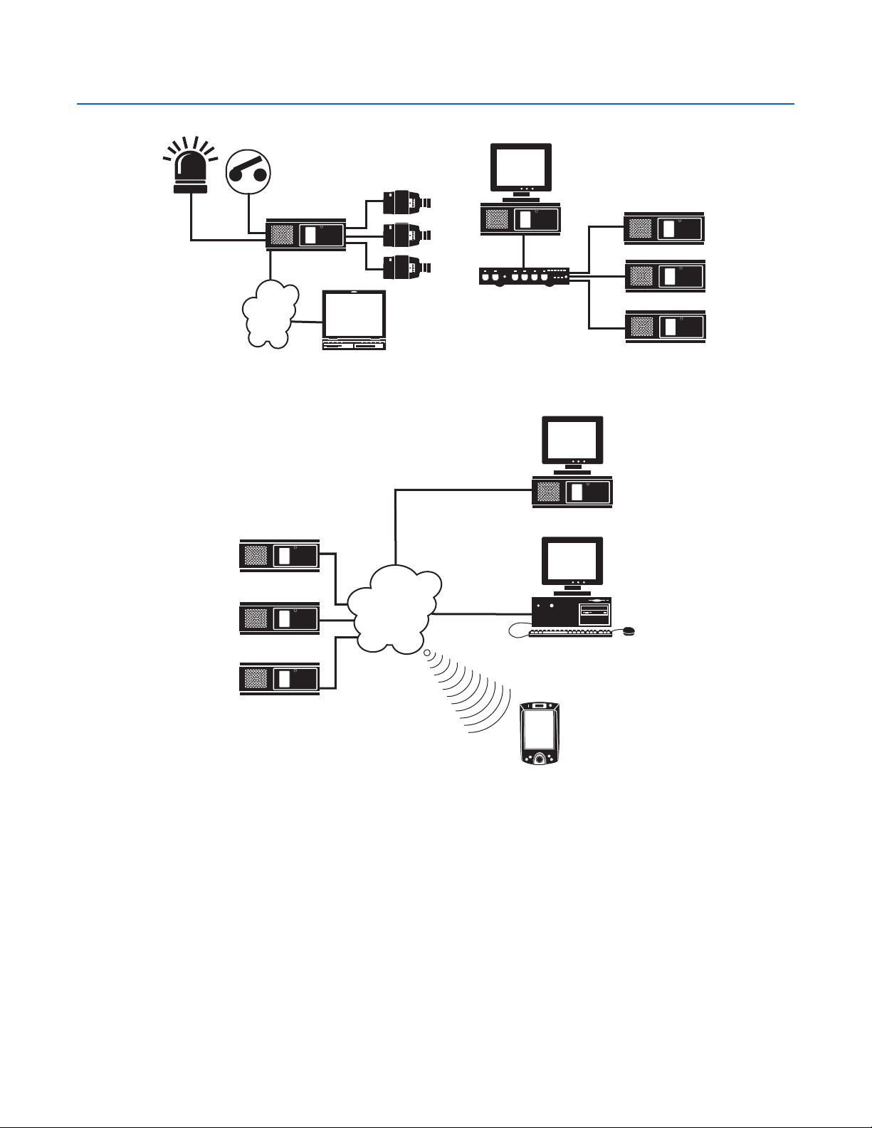
Application Examples
DX8000 SERVER DVR
CAMERA
LAN/WAN
PC CLIENT
Figure 1. System with Single DX8000
DX8000 SERVER DVR
DX8000 SERVER DVR
LAN/WAN
DX8000
FAST ETHERNET SWITCH
DX8000
DX8000
DX8000
Figure 2. System with Multiple DX8000s
DX8000 SERVER DVR
WWW CLIENT
DX8000 SERVER DVR
MOBILE CLIENT
Figure 3. System with Multiple DX8000s and Multiple Clients
Refer to the Operation/Programming manual for instructions on how to operate and program the DX8000 Series DVR.
14 C623M-C (3/05)
Page 15
Equipment Rack Mounting
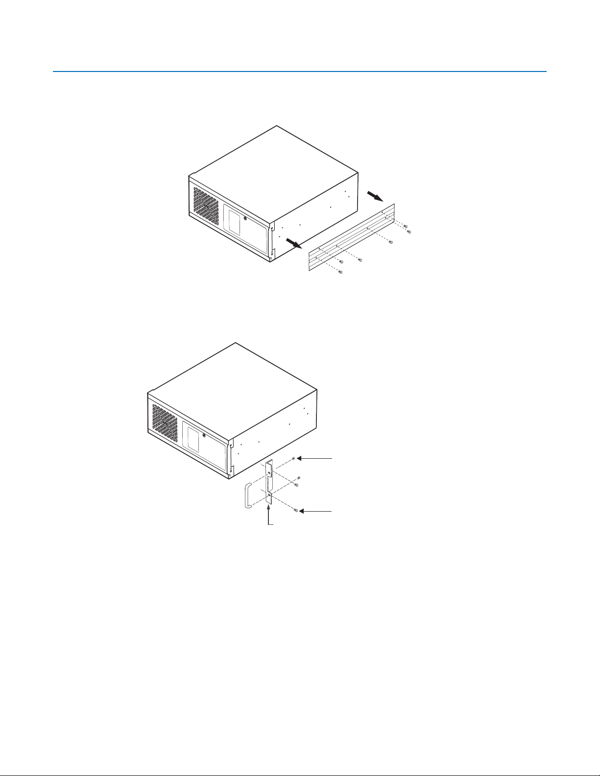
To install the unit in an equipment rack:
1. Remove the 12 screws fastening both left and right side plates to the unit. Save the side plates and screws for possible future use.
Figure 4. Remove Left and Right Side Plates
2. Attach the handles to the rack ears using the four provided 10-32 x 0.375-inch Phillips screws. Refer to Figure 5.
3. Using two of the supplied #4 sheet metal Phillips 0.375-inch pan head screws for each side, attach the rack ears to the unit.
(4) SCREWS,
10-32 X 0.375-INCH
PHILLIPS, FLAT HEAD
WITH WASHERS
(4) SCREWS, #4, SHEET METAL, PAN HEAD,
RACK EAR
PHILLIPS BLACK, 0.375-INCH (2 EACH SIDE)
Figure 5. Attaching Rack Ears and Handles
C623M-C (3/05) 15
Page 16
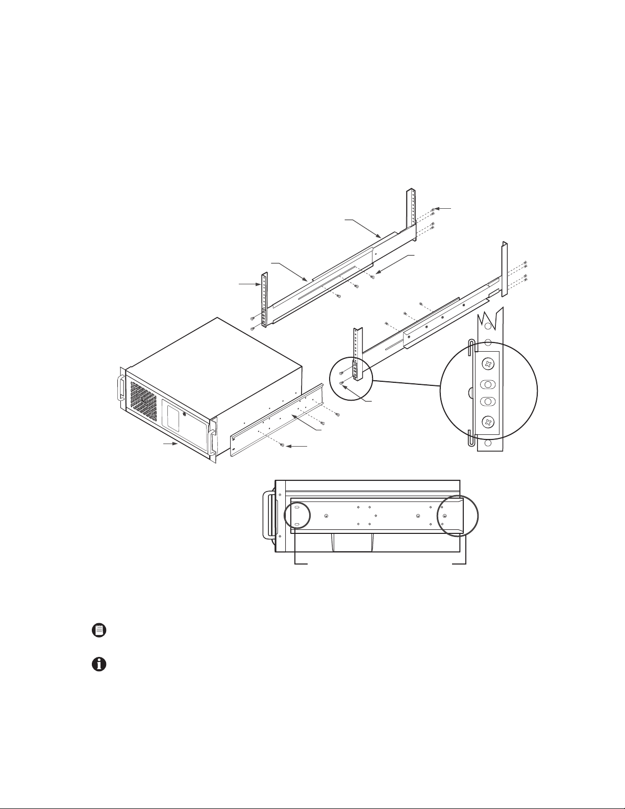
4. Using the remaining six #4 sheet metal Phillips 0.375-inch pan head screws, attach the two chassis brackets to the left and right sides of
the unit. Refer to Figure 6.
5. Assemble both sets of front and rear mounting rails using three 8-32 x 0.375-inch pan head screws and locking washers for each side.
6. Using six of the 10-32 x 0.375 Phillips flat head screws per side, attach the assembled mounting rails to a 19-inch (48.26 cm) equipment
rack or console.
7. Place the unit onto the mounting rails. It should slide in and out of the rack easily. This step may require two persons to lift and slide the
unit into place.
8. Fasten the rack ears to the equipment rack using the four 10-32 x 0.750-inch pan head screws and nylon washers.
(8) SCREWS,
REAR MOUNTING RAIL
10-32 X 0.375-INCH,
FLAT HEAD
RECORDER/ VIEWSTATION
FRONT MOUNTING RAIL
RACK
(6) SCREWS,
8-32 X 0.375-INCH,
PAN HEAD WITH LOCK
WASHERS
(4) SCREWS,
10-32 X 0.375-INCH
FLAT HEAD
BRACKET (SIDE VIEW)
(6) SCREWS, #4, SHEET METAL, PAN HEAD,
PHILLIPS BLACK, 0.375-INCH (3 EACH SIDE)
SLOTTED HOLES
TOWARDS FRONT
OF UNIT
TAPERED ENDS
TOWARDS REAR
OF UNIT
Figure 6. Rack Mount Installation
NOTE: Pelco recommends at least one rack unit (1.75 inches or 4.44 cm) of spacing between units.
IMPORTANT: Slots and openings in the cabinet provide ventilation and prevent the unit from overheating. Do not block these openings.
Never place the DVR near or over a radiator or heat register. Do not place it in a built-in installation, such as a rack, unless proper ventilation is provided.
16 C623M-C (3/05)
Page 17
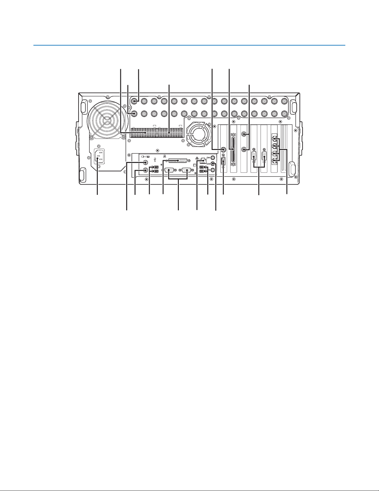
Back Panel Layout
IN1 IN2 IN3 IN4 IN5 IN6 IN7 IN8 IN9 IN10 IN11 IN12 IN13 IN14 IN15 IN16
ALARM INPUTS RELAYOUTPUTS
12245678GND
91011121314151
12245678GND
6
910111213141516
Figure 7. Back Panel Layout
Autoranging AC Power Input (voltage range between 100 VAC and 240 VAC, 50/60 Hz)
CRT
OUT16OUT15OUT14OUT13OUT12OUT11OUT10OUT9OUT8OUT7OUT6OUT5OUT4OUT3OUT2OUT1
Alarm Inputs – 16 normally closed inputs
Camera Outputs – 8 or 16 BNC camera outputs
Camera Inputs – 8 or 16 BNC camera inputs
Relay Outputs – 16 normally open outputs
S-Video Output (disabled)
Ultra SCSI Adapter (optional)
Programmable Analog Display Card Outputs (optional) – 2 BNC monitor outputs
4 RJ-45 Extended Peripheral Connectors (RS-422/RS-485 compliant)
Audio Inputs (optional) – 8 or 16 channels
VGA Monitor Output – 15-pin output
Audio Output
High-Speed USB 2.0 Ports – 2 USB ports on front of unit and 4 on rear of unit
Ethernet Adapter Port – 100 Mbps port
Two 9-pin Serial Ports (disabled)
LPT1 Printer Port – 25-pin port
Keyboard (PS/2) Input
Mouse (PS/2) Input
C623M-C (3/05) 17
Page 18
Hardware Setup
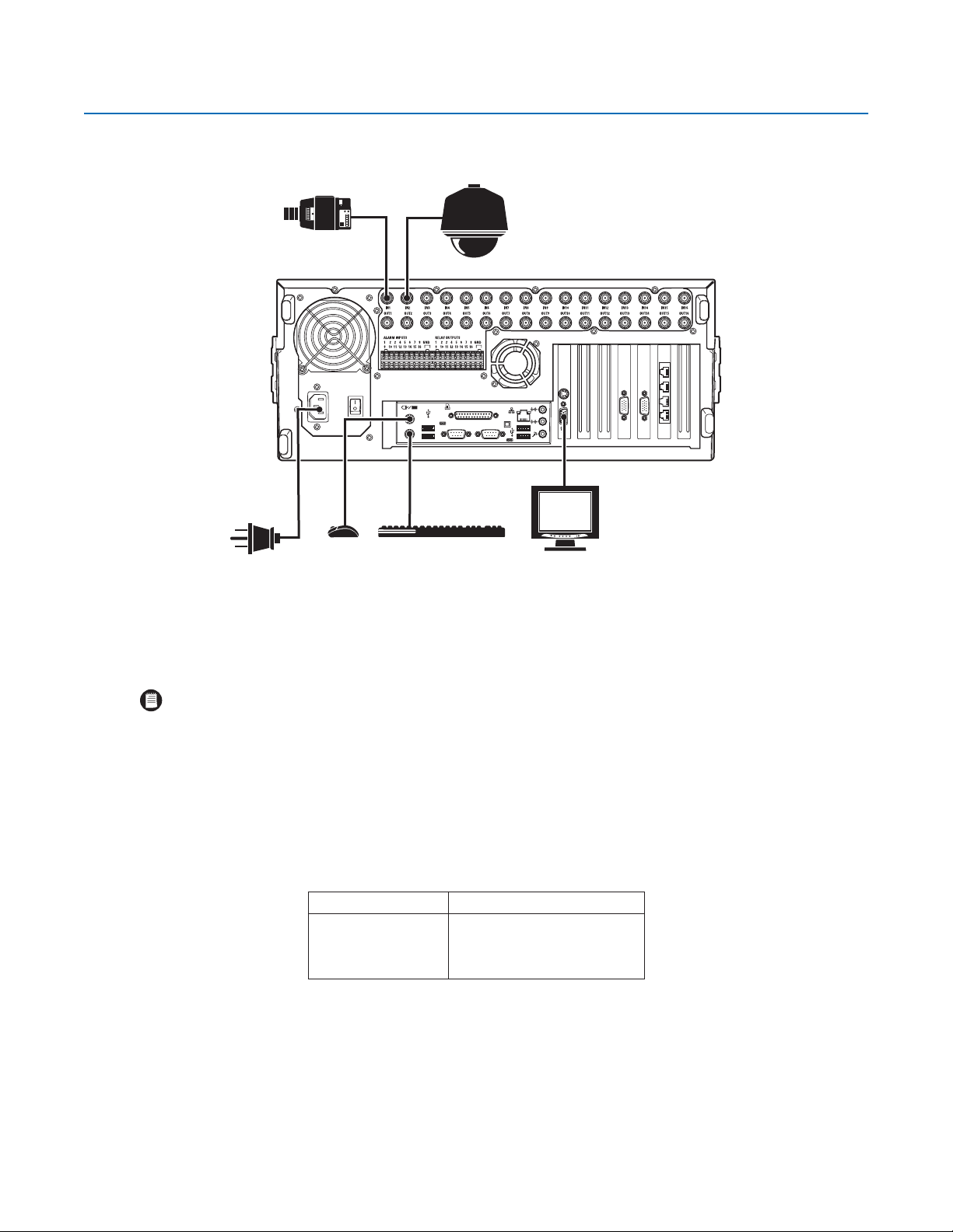
BASIC CONNECTIONS
CAMERA
SPECTRA
POWER
CONNECTION
MOUSE
Make the following connections on the rear of the recorder. Refer to Figure 8.
Connect the appropriate power cord to the back of the unit and to a power source.
NOTE: The DX8000 contains an autoranging power supply. It is recommended that the recorder be connected to an uninterruptible power
supply (UPS) capable of supplying 2 A for 120 VAC power systems or 1 A for 230 VAC power systems.
Connect the mouse to the top PS/2 input.
KEYBOARD
Figure 8. Basic Connections
VGA
Connect the keyboard to the bottom PS/2 input.
Connect a VGA monitor (not supplied).
Connect the cameras to the BNC connectors. Refer to Table A for video coaxial cable requirements. Connect power to the cameras.
Table A. Video Coaxial Cable Requirements
Cable Type* Maximum Distance
RG59/U 750 ft (229 m)
RG6/U 1,000 ft (305 m)
RG11/U 1,500 ft (457 m)
*Minimum cable requirements:
75 ohms impedance
All-copper center conductor
All-copper braided shield with 95% braid coverage
When connecting cameras using these types of cable, use a
patch panel. Do not connect these cables directly to the
DX8000.
18 C623M-C (3/05)
Page 19
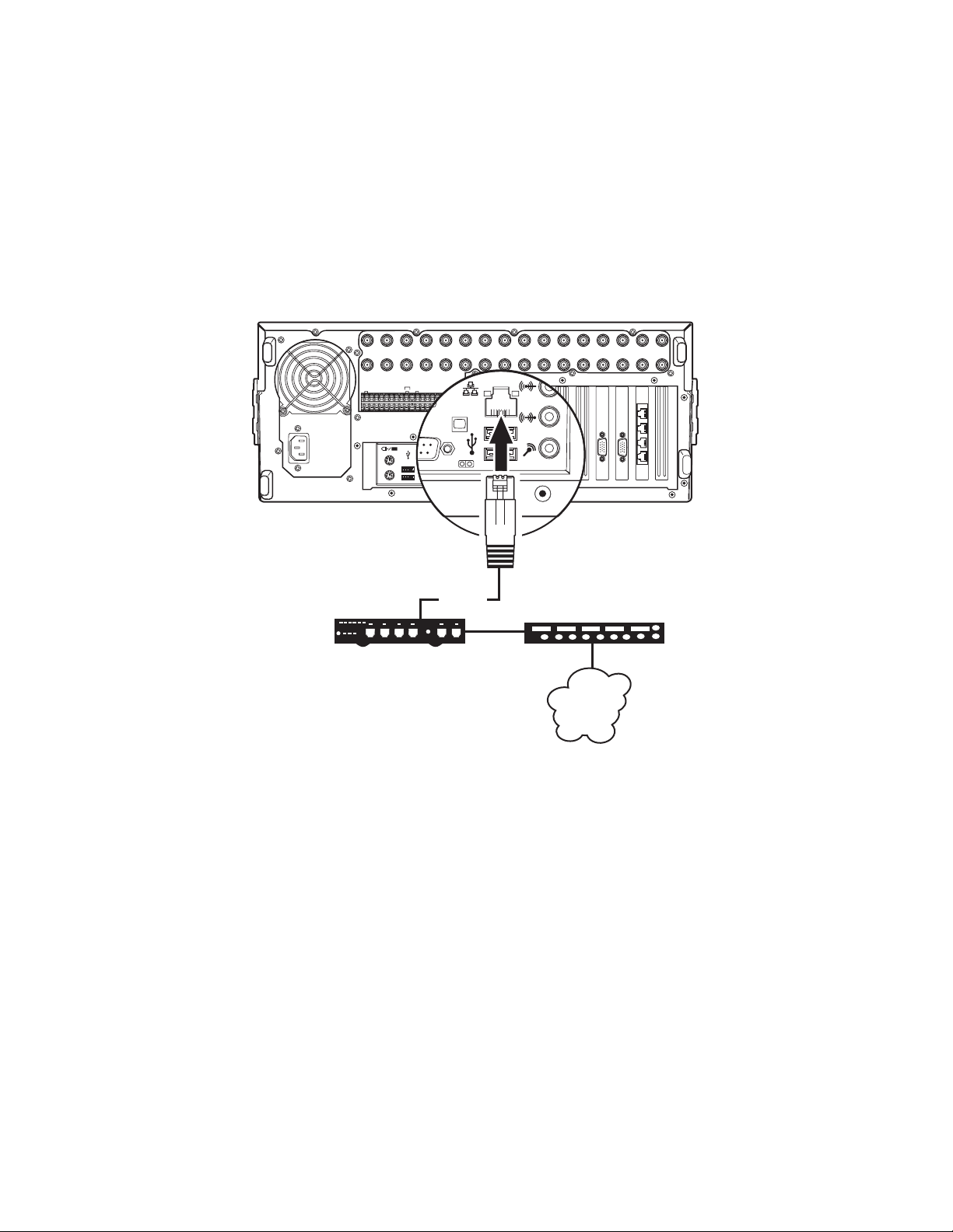
NETWORK SETUP
The DX8000 Series DVR supports remote viewing and administration in client-server and peer-to-peer configurations. The DX8000 is compatible
with the TCP/IP protocol and Fast Ethernet (100BaseT) network connection. Consult your network administrator before installing the DX8000 to
avoid possible network conflicts.
For TCP/IP access, connect the DX8000 to a 100 Mbps, switched Ethernet network. Use standard Cat5 or better UTP cable with RJ-45
connectors.
To configure the DX8000 hardware for network access:
1. Connect one end of the UTP cable to the network port on the back panel of the DX8000 as shown in Figure 9.
2. Connect the other end of the UTP cable to an available port on a standard Fast Ethernet switch.
IN1 IN2 IN3 IN4 IN5 IN6 IN7 IN8 IN9 IN10 IN11 IN12 IN13 IN14 IN15 IN16
ALARMINPUTS RELAY OUTPUTS
1 2245678GND
910111213141516
1 2245678GND
910111213141516
CRT
CAT5 UTP
FAST ETHERNET SWITCH
ROUTER
LAN/WAN
INTERNET
Figure 9. LAN/WAN Cable Connection
OUT16OUT15OUT14OUT13OUT12OUT11OUT10OUT9OUT8OUT7OUT6OUT5OUT4OUT3OUT2OUT1
C623M-C (3/05) 19
Page 20
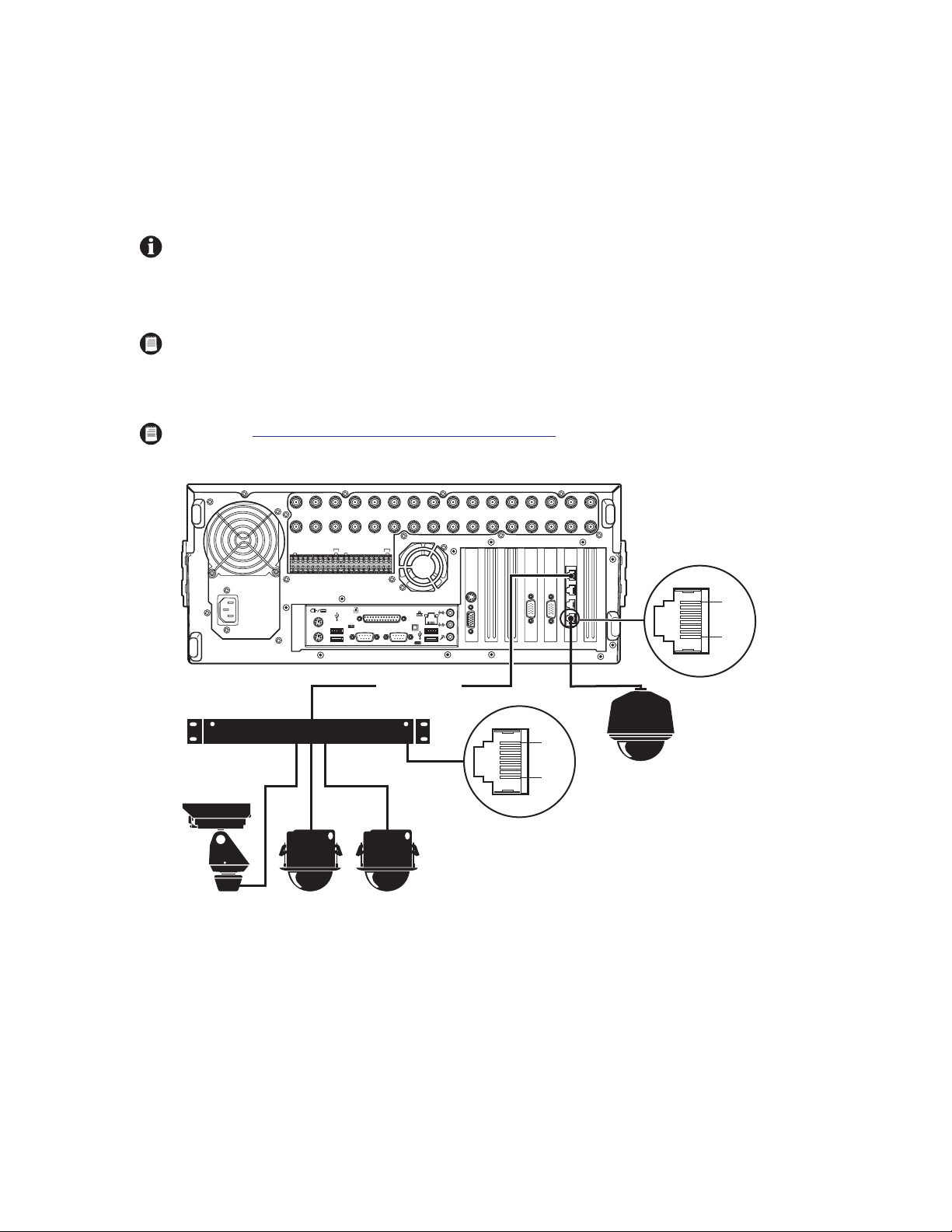
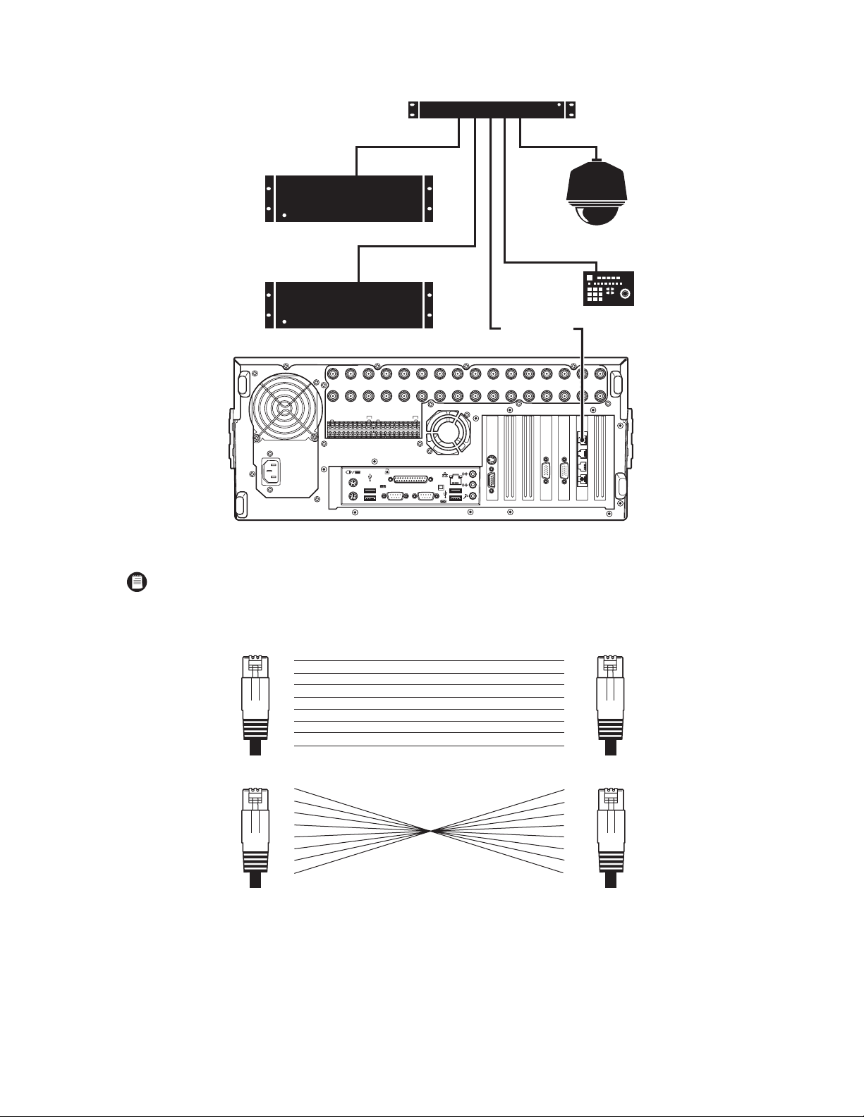
RS-422/RS-485 COMMUNICATION PORT SETUP
The DX8000 Series DVR features four independently configurable RJ-45 communication ports. All ports are compatible with both RS-422 and RS-485
interface standards. Each port can communicate with and control a variety of PTZ devices. Examples include Pelco’s Spectra™ III dome enclosures
and Esprit® positioning systems. The example configuration illustrated in Figure 10 shows a DX8000 connected directly to up to four PTZ devices
and indirectly to up to 16 devices through Pelco’s CM9760-CDU-T code distribution unit. Figure 11 illustrates the connection of a variety of
RS-422/RS-485 compatible devices including the DX8000. This example highlights the P and D protocol data merging capability of Pelco’s
CM9760-DMR data manager.
IMPORTANT: To operate properly, devices must be compatible with either the RS-422 or RS-485 interface standards and must be able to
communicate using Pelco’s P, D, or Coaxitron® protocols.
1. Using unshielded twisted pair (UTP) cable, connect up to four RS-422/RS-485 compatible devices to the RJ-45 connector jacks provided on
the rear panel of the unit.
NOTE: Pelco recommends using 22 or 24 gauge UTP cable. Category 5 UTP is recommended for cable runs greater than 400 feet.
2. Set the communication parameters for both the DX8000 and the PTZ device. Communication parameters are baud rate, parity (odd or even),
number of parity bits, number of data bits, and number of stop bits.
NOTE: Refer to RS-422/RS-485 Communication Port Software Configuration on page 42 for instructions on setting up your DVR’s commu-
nication parameters. Refer to the documentation included with your PTZ device for instructions on configuring its communication settings.
CM9760-CDU-T
PTZ
IN1 IN2 IN3 IN4 IN5 IN6 IN7 IN8 IN9 IN10 IN11 IN12 IN13 IN14 IN15 IN16
ALARMINPUTS RELAY OUTPUTS
1 2245678GND
910111213141516
1 2245678GND
910111213141516
ROLLOVER CABLE
PTZ PTZ
CRT
PIN 8
PIN 1
PIN 1 = TX+
PIN 2 = TX.
.
.
.
PIN 7 = RXPIN 8 = RX+
Figure 10. RS-422/RS-485 Configuration Example 1
OUT16OUT15OUT14OUT13OUT12OUT11OUT10OUT9OUT8OUT7OUT6OUT5OUT4OUT3OUT2OUT1
PIN 8
PIN 1
PIN 1 = TX+
PIN 2 = TX.
.
.
.
SPECTRA
PIN 7 = RXPIN 8 = RX+
20 C623M-C (3/05)
Page 21
CM9760-DMR
CM6800
PTZ
1-16
KBD300A
CM6800
IN1 IN2 IN3 IN4 IN5 IN6 IN7 IN8 IN9 IN10 IN11 IN12 IN13 IN14 IN15 IN16
ALARMINPUTS RELAY OUTPUTS
12245678GND
910111213141516
12245678GND
910111213141516
ROLLOVER CABLE
OUT16OUT15OUT14OUT13OUT12OUT11OUT10OUT9OUT8OUT7OUT6OUT5OUT4OUT3OUT2OUT1
CRT
Figure 11. RS-422/RS-485 Configuration Example 2
NOTE: Different types of devices may require alternative cable wiring schemes. Wiring schemes commonly used by Pelco products include
straight and rollover types. Refer to the documentation included with your PTZ device to ensure that cables and connectors are wired
appropriately. Figure 12 illustrates straight and rollover cable wiring schemes
PIN
1
2
3
RJ-45
4
5
6
7
8
STRAIGHT CABLE
PIN
1
2
3
RJ-45 RJ-45
4
5
6
7
8
ROLLOVER CABLE
PIN
PIN
1
2
3
4
5
RJ-45
6
7
8
1
2
3
4
5
6
7
8
Figure 12. Cable Wiring Schemes
C623M-C (3/05) 21
Page 22
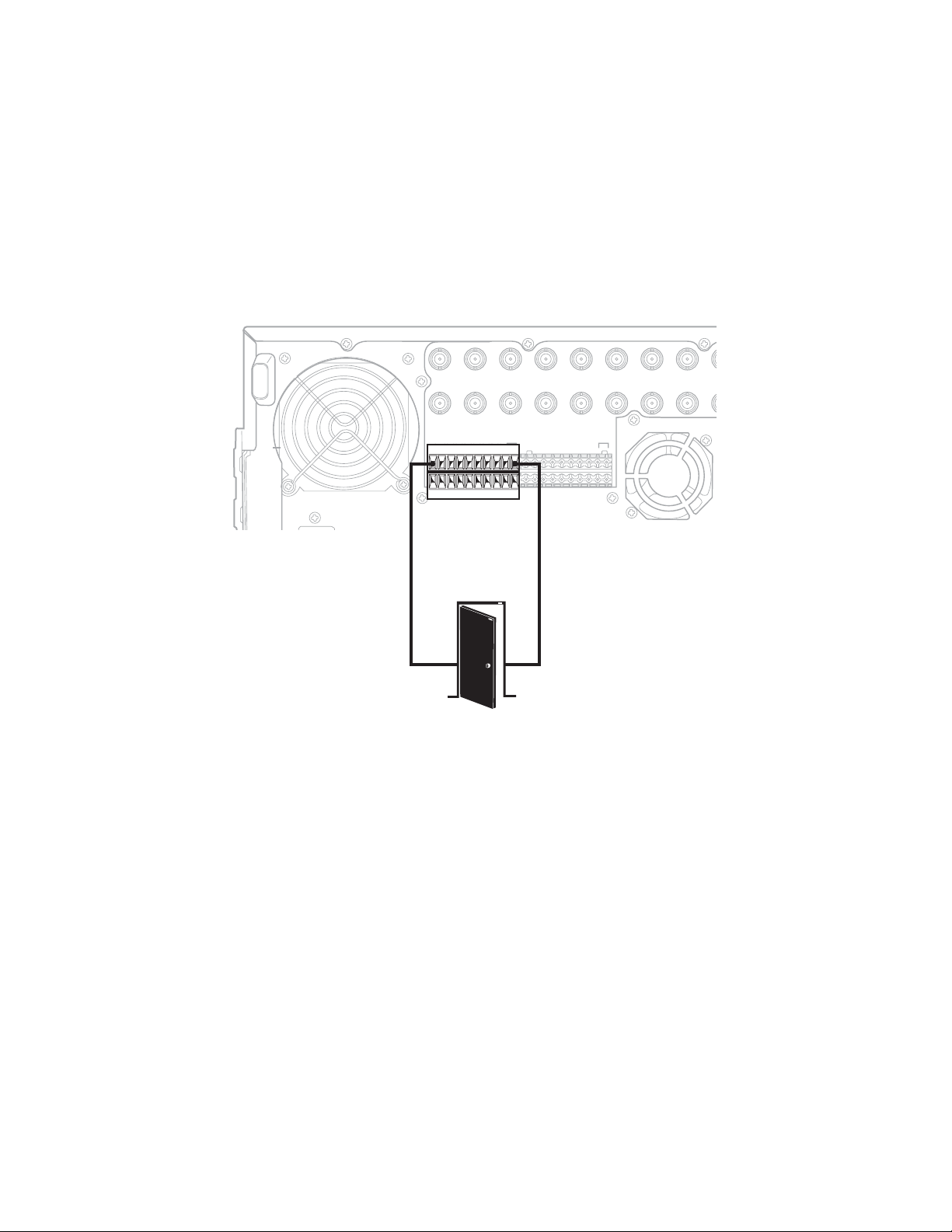
ALARM INPUT INSTALLATION
IN9 IN10 IN11 IN12 IN13 IN14 IN15 IN16
OUT16OUT15OUT14OUT13OUT12OUT11OUT10
OUT9
CRT
The DX8000 has either 8 or 16 dry contact alarm inputs, depending on your system’s configuration. Each input is programmed to function as
either a normally open or normally closed circuit.
To wire an alarm input:
1. Insert the green terminal blocks into the alarm sockets on the back panel of the recorder.
2. Connect one wire from the source device to one of the sensor input terminals 1 through 16.
3. Connect a second wire from the source device to a GND terminal.
4. Refer to the Operation/Programming manual for information on how to program the alarm inputs.
IN1 IN2 IN3 IN4 IN5 IN6 IN7 IN8 IN9
ALARM INPUTS RELAYOUTPUTS
1 2245678GND
910111213141516
1 2245678GND
910111213141516910111213141516
ALARM
OUTPUT 1
Figure 13. Alarm Terminal Installation
GND
OUT9
OUT8OUT7OUT6OUT5OUT4OUT3OUT2OUT1
22 C623M-C (3/05)
Page 23
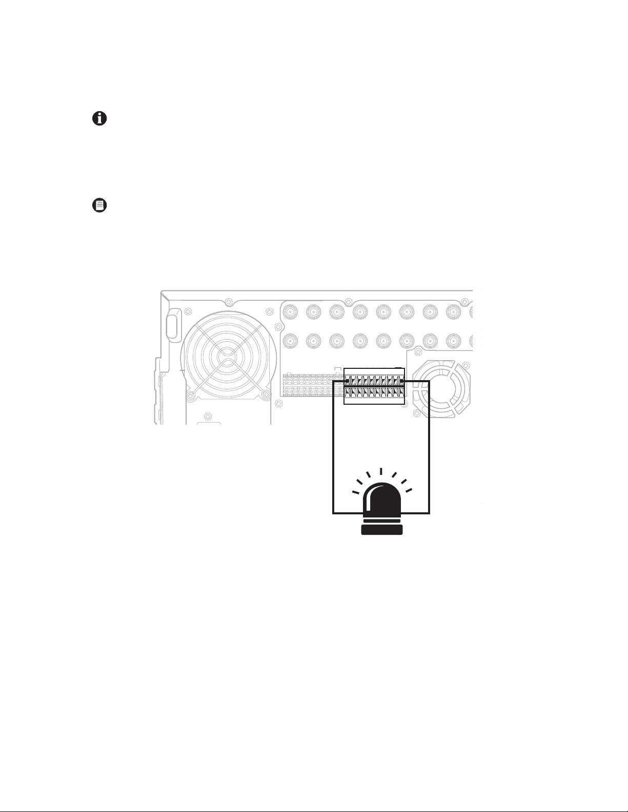
RELAY OUTPUT INSTALLATION
IN9 IN10 IN11 IN12 IN13 IN14 IN15 IN16
OUT16OUT15OUT14OUT13OUT12OUT11OUT10
9OUT9
9 10 11 12 13 14 15 16
CRT
The DX8000 has either 8 or 16 relay outputs, depending on your system’s configuration. Each output is programmed to function as either a
normally open or normally closed circuit. A signal from a relay output will operate the device connected to the output.
IMPORTANT: The maximum relay power rating is 120 VAC, 0.5 A; 24 VDC, 1 A.
To wire a relay output:
1. Insert the blue terminal blocks into the relay sockets on the back panel of the recorder.
2. Connect one wire from the device to one of the relay output terminals 1 through 16.
NOTE: Relay outputs do not have to correspond numerically to alarm inputs. All sensor input and relay output actions can be linked
through programming.
3. Connect a second wire from the relay device to a GND terminal.
4. Refer to the Operation/Programming manual for information on how to program relay outputs.
IN1 IN2 IN3 IN4 IN5 IN6 IN7 IN8 IN9
ALARM INPUTS RELAYOUTPUTS
1 2245678GND
910111213141516
1 2245678GND
910111213141516
RELAY
OUTPUT 1
Figure 14. Relay Terminal Installation
GND
OUT
OUT8OUT7OUT6OUT5OUT4OUT3OUT2OUT1
C623M-C (3/05) 23
Page 24
Software Setup
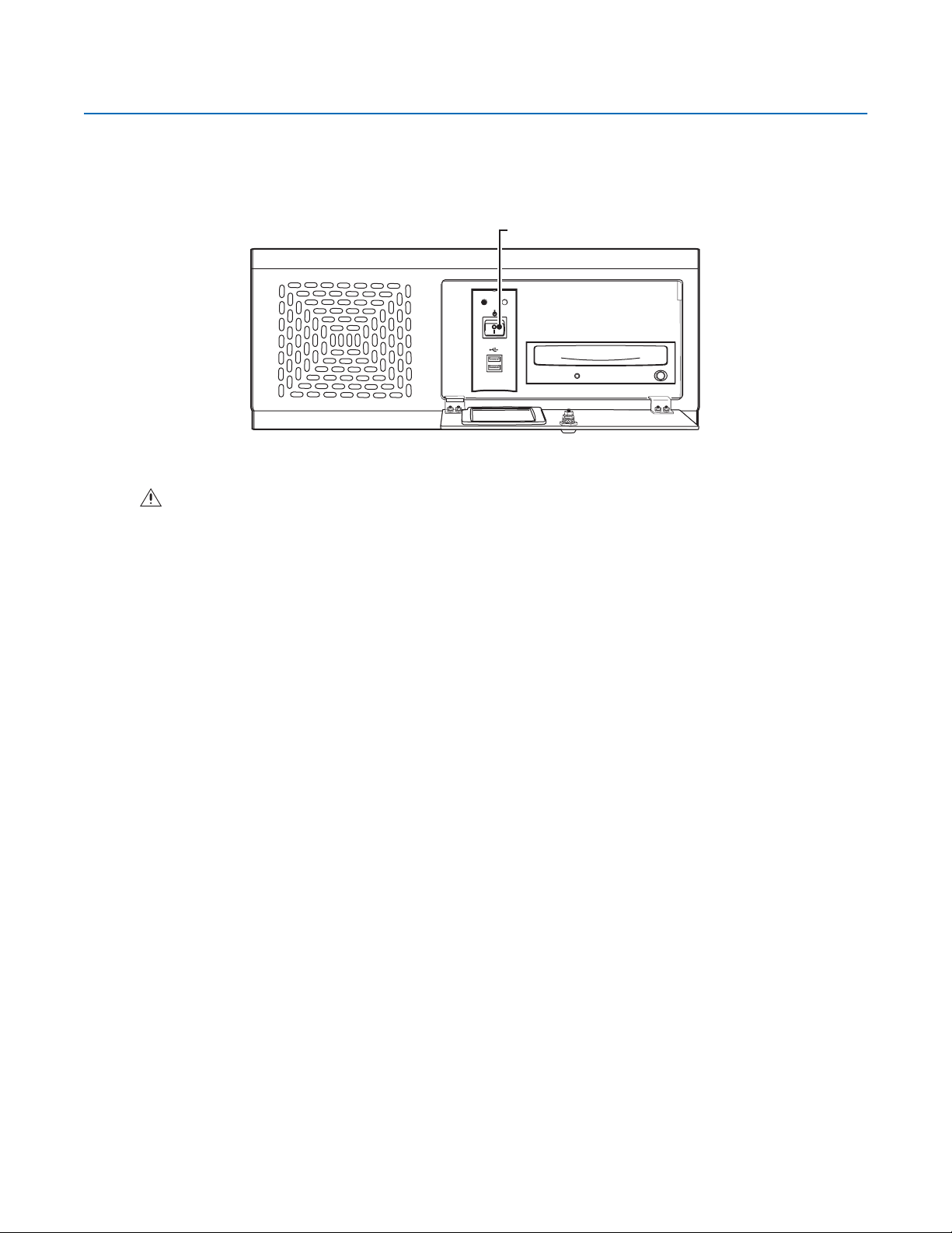
STARTING THE UNIT
Once the system has been installed and basic connections have been made, open the front panel of the DVR. Press the power switch. Wait while
the unit starts (this may take several minutes).
WARNING: Be sure to put on gloves before removing or inserting the filter.
POWER SWITCH
POWER HDD
USB
Figure 15. Front Panel and Power Switch
24 C623M-C (3/05)
Page 25
LOGGING IN FOR THE FIRST TIME
To access the features of the DX8000 Series DVR, each user must log in with a valid user name and password. There are four user access levels
or groups that can be configured on the DX8000. Access levels range from the Administrator group, with the most rights and privileges, to the
Restricted group, with the least rights and privileges. Refer to the Definition of User Access Levels section of the Operation/Programming manual
for information on user group rights and permissions.
The DX8000 comes equipped with two built-in user accounts. Each time the unit is started, a default user account called “Guest” is automatically
activated. The Guest account is granted only limited access to the DX8000 and is allowed no access to system configuration utilities. A second
built-in user account, named “Admin”, provides full access to the operations and configuration features of the DX8000. To log in with the Admin
account, follow the directions below.
To log in with the Admin account:
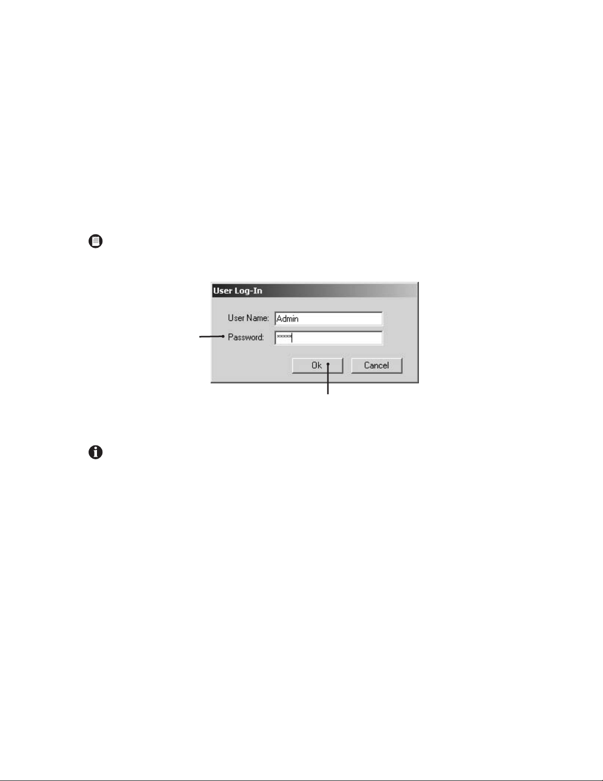
1. Click File > User Log-in.
2. Enter Admin in the User name field and Admin in the Password field.
NOTE: User names and passwords are case-sensitive.
1. Click OK.
Figure 16. User Log-in Dialog Box
For security reasons, you are required to change the Admin password immediately after logging in for the first time. Passwords must be
between six and ten characters long and cannot include spaces or special characters. Follow the directions on the next page to change the
Admin password.
C623M-C (3/05) 25
Page 26
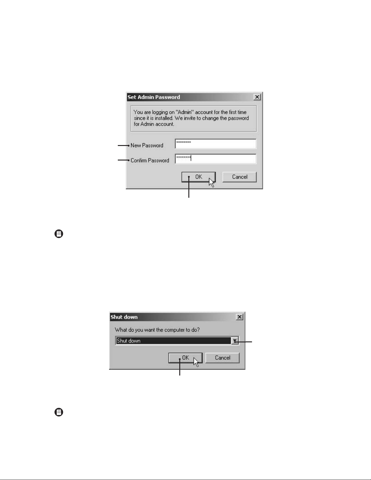
To complete the mandatory password change for the Admin account:
The Set Admin Password dialog box opens automatically.
1. Enter a new password in the New Password field.
2. Enter the password again in the Confirm Password field to confirm the password.
3. Click OK.
NOTE: Only users with Administrator and Power User accounts are allowed access to DX8000’s setup functions.
SHUTTING DOWN
To shut down the DX8000 Series DVR:
1. Go to File > Exit.
2. Select Shut down.
3. Click OK.
Figure 17. Set Admin Password Dialog Box
Figure 18. Shut Down Dialog Box
NOTE: You must have Power User or Administrator access to shut down the DX8000. Refer to the Operation/Programming manual for
information on user security levels. You must also have a Windows password to shut down. For information on the Windows default
password, refer to the Important Security Information for System Admisnistrators guide.
26 C623M-C (3/05)
Page 27
EXITING TO WINDOWS OPERATING SYSTEM
Some of the steps involved in the configuration of a DX8000 Series DVR require exiting to the operating system.
NOTE: You must have Power User or Administrator access to shut down the DX8000. Refer to the Operation/Programming manual for
information on user security levels. You must also have a Windows password to exit from the DX8000 application to the Windows
operating system. For information on the Windows default password, refer to the Important Security Information for System
Admisnistrators guide.
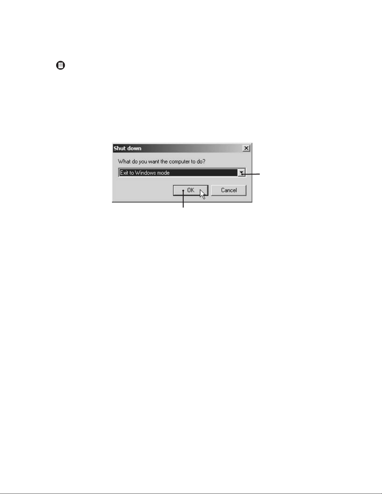
To exit the DX8000 application and log into the Windows operating system:
1. Go to File > Exit.
2. Select Exit to Windows. The Shut down dialog box opens.
3. Click OK.
Figure 19. Shut Down Dialog Box
The Log On to Windows dialog box opens.
4. Enter the Windows password and click OK. The system logs you into the Windows operating system.
C623M-C (3/05) 27
Page 28
SETTING THE SYSTEM LANGUAGE
The DX8000 supports six languages. The DVR comes from the factory configured for English (United States). To configure the system properly for
a language other than English, you must change the regional setting in the Windows operating system and the language setting of the DX8000.
The following regional settings are available for the DX8000:
• English (United States)
• French (France)
• German (Germany)
• Italian (Italy)
• Portuguese (Brazil)
• Spanish (Spain)
English (United States) is the default setting.
CONFIGURING THE REGIONAL SETTING IN THE WINDOWS OPERATING SYSTEM
In the example below, the location is changed from English (United States) to Spanish (Spain).
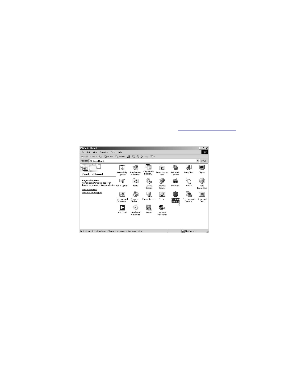
1. Exit the DX8000 application and return to the Windows operating system. Refer to Exiting to Windows Operating System
2. Click Start > Settings > Control Panel. The Control Panel appears. Double-click Regional Options.
Figure 20. Control Panel with Regional Options Selected
on page 27.
28 C623M-C (3/05)
Page 29

3. The Regional Options dialog box opens.
4. Click the arrow to open the location drop-down list.
5. Change the location to Spanish (Spain).
6. Click Apply.
7. Click Set Default.
Figure 21. Regional Options Dialog Box
C623M-C (3/05) 29
Page 30

8. The Select System Locale dialog box opens. Select “Spanish (Spain)” from the drop-down box.
9. Click OK.
Figure 22. Select System Locale Dialog Box
10. The Regional Options dialog box opens. Click Apply.
Figure 23. Regional Options Dialog Box
30 C623M-C (3/05)
Page 31

11. The General dialog box opens. Click Yes.
Figure 24. General Dialog Box
12. The Change Regional Options dialog box opens. Click Yes.
Figure 25. Change Regional Options Dialog Box
The new settings take effect after the computer restarts. The DX8000 will support Spanish settings for numbers, currency, times and dates.
Follow these same steps to change the location back to English (United States) or to select another location.
C623M-C (3/05) 31
Page 32

CONFIGURING THE LANGUAGE SETTING OF THE DX8000
NOTE: This feature is unavailable in the current software release. It will be available in future releases.
You must have Administrator or Power User access to configure the language setting of the DX8000.
1. Start the DX8000 if it is not already running, and then log in as a Power User or Administrator.
2. Click .
3. Click . The System page is displayed.
4. Select the appropriate language from the drop-down box.
5. Click Apply.
Figure 26. System Page: Selecting the Language
32 C623M-C (3/05)
Page 33

SETTING THE SYSTEM TIME
Time should be set on the DX8000 before it is put into use. Setting the internal clock for each DVR on the network ensures that each accurately
reflects the local time.
To set system time:
1. Click .
2. Click . The System page is displayed.
3. From the Date/Time drop-down box, select the current month, day, and year.
4. Select the current time.
5. Click Update.
6. Select the correct time zone from the drop-down box.
7. Click Update.
8. Click Apply.
Figure 27. Setting the System Time
C623M-C (3/05) 33
Page 34

ENABLING AND USING CTRL+ALT+DEL
Enabling the Ctrl+Alt+Del key combination allows you to open the Windows Task Manager dialog box to perform Windows system
administration tasks. To complete the procedure, you must be logged on to the DX8000 as an administrator or a member of the administrators
group on a computer that is part of a network domain.
IMPORTANT: The DX8000 keyboard is remapped. To see which keys replace the Ctrl and Alt keys, refer to the Important Security
Information for System Administrators guide.
To enable the Ctrl+Alt+Del key combination:
1. Click .
2. Click . The System page is displayed.
3. From the Setup Ctrl + Alt + Del key combination area, click the Enable Ctrl+Alt+Del key combination selection check box.
4. Click Apply.
5. Reboot the DX8000.
USING CTRL+ALT+DEL
You must enable the Ctrl + Alt + Del key combination and verify your actual keyboard mapping. In some cases, the DX8000 keyboard is remapped
and the actual Ctrl and Alt key function is assigned to other keys. For information on which keys replace the Ctrl and Alt keys, refer to the
Important Security Information for System Administrators guide.
Ctrl+Alt+Del allows you to access the Windows Task Manager dialog box from within the DX8000 shell. When you exit the Windows
environment, you are returned to the DX8000 shell. In this case, you do not have to log back into the DX8000.
To access the Windows Task Manager dialog box:
1. Press the assigned keyboard keys that implement the Ctrl + Alt + Del function. The Windows Security dialog box opens.
2. In the Windows Security dialog box, click Task Manager. The Windows Task Manager window opens.
To return to the DX8000 shell without rebooting the DX8000, exit the Windows Task Manager dialog box.
34 C623M-C (3/05)
Page 35

NETWORK SOFTWARE CONFIGURATION
Using the TCP/IP protocol, up to five DX8000 Series DVRs can be networked together for remote viewing and management. In addition, up to five
simultaneous PC, web, and mobile clients can connect to each DVR. The DX8000 Series DVR supports both static IP addressing and dynamic
addressing through Dynamic Host Configuration Protocol (DHCP). Consult your network administrator for more information regarding IP address
configuration.
NOTE: The system must be turned on, connected to a network, and you must be logged in with either Power User or Administrator access
to configure network software settings.
IMPORTANT: You must reboot the DVR for any network configuration changes to take effect.
To begin the network setup process:
1. Click .
2. Click . The Network page is displayed.
3. Click the Network tab if it is not already visible.
4. Enter a new name for your DVR in the Site Name field. (Site names can be up to 30 characters in length. The default site name is DX8000.)
5. Enter a unique system ID for your DVR in the System ID field. (System IDs must start with a letter, must be 15 characters or less, and cannot
include spaces or special characters.)
NOTE: Your DVR’s site name is used to identify your system to clients and other DX8000 servers. Your DVR’s system ID is used to uniquely
identify your system on a local area network (LAN). System IDs are required to prevent possible conflicts with other network devices.
6. Proceed to the steps for setting up DHCP or Static IP addressing in the following sections.
Figure 28. Network Setup Page: Software Configuration
C623M-C (3/05) 35
Page 36

DHCP SETUP
To configure the DVR to acquire a dynamic IP address through DHCP:
1. Click the check box labeled Obtain An IP Address Automatically (DHCP).
NOTE: Your network must support DHCP, and an active DHCP server must be present for dynamic addressing to work. Consult your network administrator for more information.
2. Click Apply.
Figure 29. DHCP Setup
36 C623M-C (3/05)
Page 37

STATIC IP SETUP
To set up a static IP address, enter the following information in the fields provided. This information can be obtained from your network administrator.
1. Verify that the Obtain An IP Address Automatically (DHCP) check box is not selected.
2. Enter a unique IP address (for example, 10.0.0.101). The last three digits must be different for each recorder (for example, 101, 102, 103,
and so forth).
3. Enter the subnet mask (for example, 255.0.0.0).
4. Enter the default gateway address (the IP address of the default router on your immediate network segment).
5. Click Apply.
Figure 30. Static IP Setup
C623M-C (3/05) 37
Page 38

TCP/IP PORT AND BANDWIDTH THROTTLE SETUP
The DX8000 uses the TCP/IP networking protocol to communicate over LAN and WAN networks. TCP/IP uses logical network ports to organize
data transmissions and to ensure that data packets are delivered to the proper application. For example, e-mail is traditionally delivered through
TCP/IP port 25 and web pages through port 80. The ports assigned to direct video and control information into and out of the DX8000 are listed
below in Table B, “TCP/IP Ports Used by the DX8000,” on page 38.
Table B. TCP/IP Ports Used by the DX8000
Port Number
9002 Yes Base port for transmission of video, audio, and interface data
9003 Yes Software upgrade
9004 Yes Emergency agent notification
9005 No Information port
13900 No Ping port
IMPORTANT: You should keep port numbers set at their default values unless there is a known conflict with your existing network
infrastructure. Consult your network administrator before changing any port information on the DX8000.
User
Configurable
Function
38 C623M-C (3/05)
Page 39
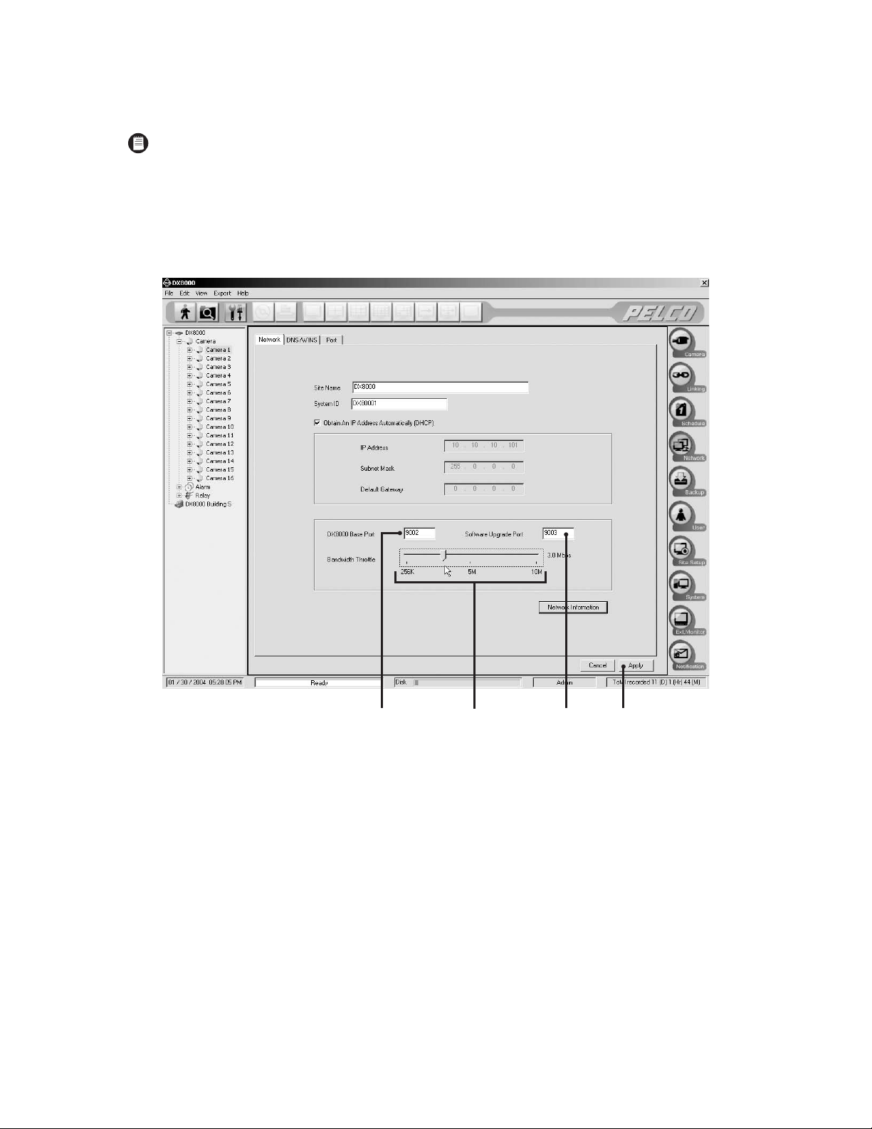
To configure TCP/IP ports and bandwidth throttle:
1. If necessary, enter a new base port number. (9002 is the default)
NOTE: Consult your network administrator when assigning or changing the port numbers. Make sure that ports are not blocked by a
firewall.
2. If necessary, enter a new software upgrade port. (9003 is the default)
3. Drag the network bandwidth throttle slider to the desired value. (Client bandwidth can be adjusted from a minimum of 256 Kbps to a
maximum of 10 Mbps in increments of 256 Kbps.)
4. Click Apply.
Figure 31. Base Port and Bandwidth Throttle Setup
C623M-C (3/05) 39
Page 40

ACCESSING NETWORK INFORMATION
To access network information such as IP and default gateway addresses:
1. Click Network Information. The IP Configuration status box is displayed.
Figure 32. IP Configuration Status Box
2. Click OK to return to the Network page.
Changes in network settings may not show up immediately in the IP Configuration status box. Allow up to 30 minutes for settings to update
or reboot your DVR for settings to change immediately.
40 C623M-C (3/05)
Page 41
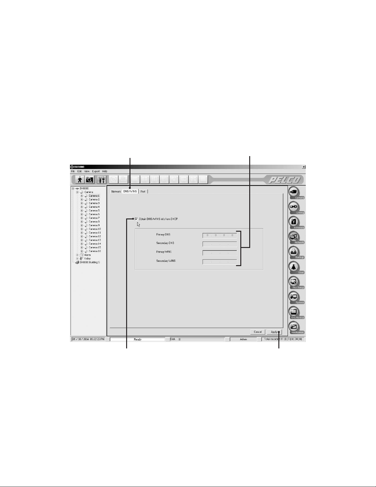
DNS/WINS SETUP
If your network supports DNS or WINS services, follow the instructions below:
1. Click the DNS/WINS tab.
2. If you are using dynamic IP addressing through a DHCP server, click the “Obtain DNS/WINS info from DHCP” check box.
3. If you are using static IP addressing, provide the following information in the appropriate fields. This information can be obtained from your
network administrator.
• Primary DNS server IP address.
• Secondary DNS server IP address.
• Primary WINS server IP address.
• Secondary WINS server IP address.
4. Click Apply to update the configuration.
Figure 33. DNS/WINS Setup
C623M-C (3/05) 41
Page 42

RS-422/RS-485 COMMUNICATION PORT SOFTWARE CONFIGURATION
NOTE: The system must be powered on, and you must be logged in as a Power User or Administrator to configure communication port
settings.
To configure the RS-422/RS-485 ports in software:
1. Click .
2. Click .
3. Click the Port tab.
4. From the drop-down box, select the port number you wish to configure.
5. Configure the port settings using the drop-down boxes provided. Refer to Table C.
6. Click Apply.
NOTE: Refer to the instructions that came with your peripheral device for correct settings.
Table C. RS-422/RS-485 Port Settings
Setting Options
Device None or Spectra
Interface Mode RS-422 or RS-485
Baud Rate 2400, 4800, 9600, 19200, 28800, 38400, 57600, or 115200
Parity None, Odd, or Even
Data Bits 5, 6, 7, or 8 bits
Stop Bits 1 or 2 bits
42 C623M-C (3/05)
Page 43
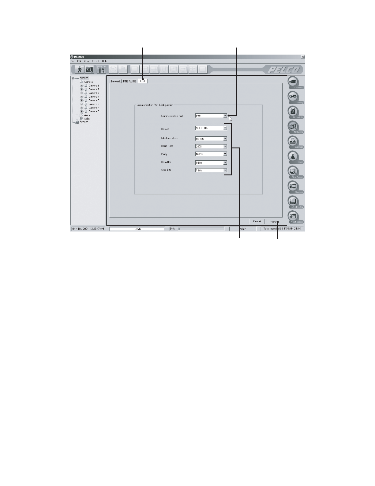
Figure 34. RS-422/RS-485 Port Setup Page
C623M-C (3/05) 43
Page 44

CLIENT SOFTWARE SETUP
RECOMMENDED SYSTEM REQUIREMENTS
The following are the minimum recommended system requirements for the DX8000 PC client, web client, and Emergency Agent software
applications.
®
• Processor: Intel
• Memory: 128 MB of RAM
• Video: AGP VGA card with minimum of 64 MB video RAM, 1024 x 768 display resolution, 32-bit color, and DirectX® 8.1 or later hardware
acceleration
• 500 MB of free disk space
• Monitor: SVGA or XGA with 1024 x 768 resolution, 32-bit color
• Operating System: Windows 2000 (SP4) or Windows XP only
• Microsoft Internet Explorer: Version 5.5 or later
INSTALLING THE PC CLIENT APPLICATION
1. Start the Windows operating system.
2. Close all programs, including any antivirus software.
3. Insert the DX8000 Resource CD into the CD-ROM drive of your PC and wait for the DX8000 Resource CD window to open.
Pentium® III, or Pentium 4 with 800 MHz minimum processor speed
Figure 35. Resource CD Screen: PC Client Installation Option
4. Click “PC Client Software.” The DX8000 Security Setup dialog box opens.
Figure 36. DX8000 Security Setup Dialog Box
5. Verify that the “Install IPSec Configurations” check box is selected.
44 C623M-C (3/05)
Page 45

IMPORTANT: IPSec is a standard security protocol used by the DX8000 Series DVR and its clients to communicate safely over a network.
Although IPSec security can be disabled at any time, it must be enabled in order to communicate with a DX8000 server.
6. Click Next. The DX8000 Client Setup dialog box opens.
Figure 37. DX8000 Client Setup Dialog Box
7. Click Next. The Software License Agreement dialog box opens.
Figure 38. Software License Agreement Dialog Box
8. Read the license agreement and select the “I accept this License Agreement” check box.
9. Click Next. The Select Installation Folder dialog box opens.
C623M-C (3/05) 45
Page 46
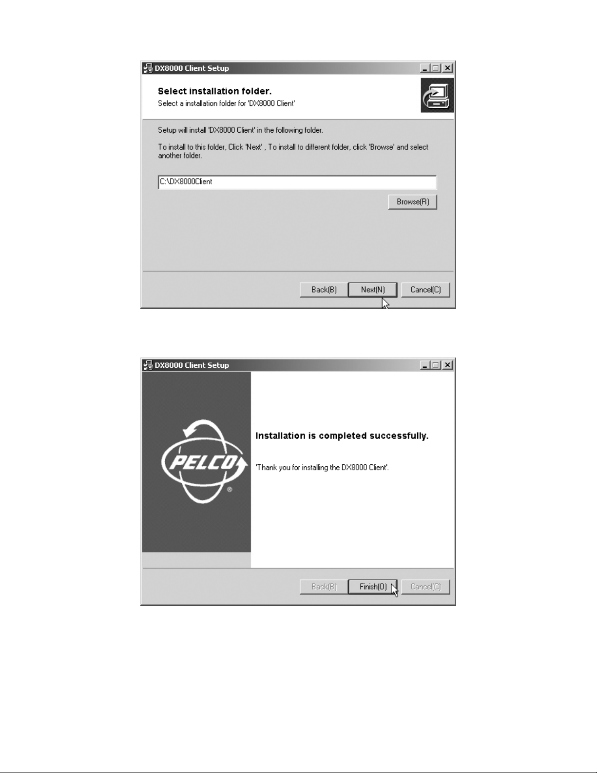
Figure 39. Select Installation Folder Dialog Box
10. Click Next to accept the default installation folder.
Figure 40. Installation is Completed Successfully Dialog Box
11. Click Finish to complete the installation process.
46 C623M-C (3/05)
Page 47

ENABLING IPSEC SECURITY SERVICES
In order to communicate with a networked DX8000 Series DVR, IPSec security must be enabled on your PC computer.
To enable IPSec security services:
1. Go to Start > Manage IPSec Policy. The DX8000 IPSec Policy dialog box opens.
Figure 41. Enabling IPSec Security for the PC Client Application
2. Select the Enable DX8000 IPSec Policy check box if it is not already selected.
DISABLING IPSEC SECURITY SERVICES
To disable IPSec security services:
1. Go to Start > Manage IPSec Policy. The DX8000 IPSec Policy dialog box opens.
Figure 42. Enabling IPSec Security for the PC Client Application
2. De-select the Enable DX8000 IPSec Policy check box.
IMPORTANT: Disabling IPSec security services may hamper your PC’s ability to communicate with DX8000 servers. Consult your system
administrator before disabling IPSec security.
NOTE: Refer to the DX8000 Client Applications manual for instructions on using the DX8000 Client applications.
C623M-C (3/05) 47
Page 48

INSTALLING THE CLIENT EMERGENCY AGENT APPLICATION
1. Start the Windows operating system.
2. Close all programs, including any antivirus software.
3. Insert the DX8000 Resource CD into the CD-ROM drive of your PC and wait for the DX8000 Resource CD window opens.
Figure 43. Resource CD Screen: Emergency Agent Installation Option
4. Click PC Emergency Agent Software to install the Client Emergency Agent application. The DX8000 Security Setup dialog box opens.
Figure 44. DX8000 Security Setup Dialog Box
5. Verify that the “Install IPSec Configurations” check box is selected.
IMPORTANT: IPSec is a standard security protocol used by the DX8000 Series DVR and its clients to communicate safely over a network.
Although IPSec security can be disabled at any time, it must be enabled in order to communicate with a DX8000 server.
6. Click Next. The DX8000 Emergency Agent Setup dialog box opens.
48 C623M-C (3/05)
Page 49

Figure 45. DX8000 Emergency Agent Setup Program Dialog Box
7. Click Next. The Software License Agreement dialog box opens.
Figure 46. Emergency Agent Software License Agreement Dialog Box
8. Read the license agreement and select the “I accept this License Agreement” check box.
9. Click Next. The Select Installation Folder dialog box opens.
C623M-C (3/05) 49
Page 50
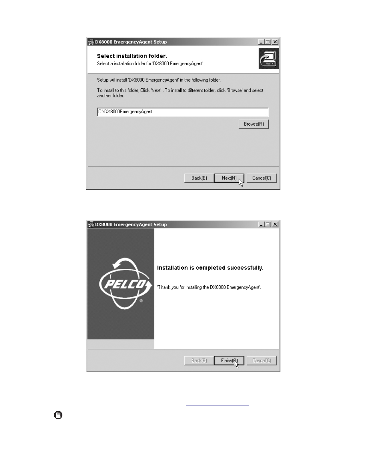
Figure 47. Select Installation Folder Dialog Box
10. Click Next to accept the default installation folder.
Figure 48. Installation is Completed Successfully Dialog Box
11. Click Finish to complete the installation process.
12. Enable IPSec Security Services. For more information, refer to Enabling IPSec Security Services
on page 47.
NOTES:
• In order to communicate with a networked DX8000 Series DVR, IPSec security must be enabled on your PC computer.
• Refer to the DX8000 Client Applications manual for instructions on using the DX8000 Client applications.
50 C623M-C (3/05)
Page 51

INSTALLING THE DX8000 VIEWER
1. Start the Windows operating system.
2. Close all programs, including any antivirus software.
3. Insert the DX8000 Resource CD into the CD-ROM drive of your PC and wait for the DX8000 Resource CD window opens.
Figure 49. Resource CD Window: Native Viewer Option
4. Click Native Viewer to install the viewer application, and then follow the installation directions.
NOTE: Refer to the DX8000 Client Applications manual for instructions on using the DX8000 Client applications.
C623M-C (3/05) 51
Page 52

INSTALLING THE DX8000 WEB CLIENT
The first time you use a web browser to connect to a DVR server, an ActiveX® control application is downloaded and installed on your local
computer. This control facilitates usage of the web client’s interactive features.
To install the DX8000 Web Client application:
1. Start Microsoft Internet Explorer web browser.
NOTE: The DX8000 Web Client application is not compatible with Netscape Navigator.
2. Enter the IP address of one of the DX8000 servers you want to connect to in the address bar. The Enter Network Password dialog box opens.
Figure 50. Enter Network Password Dialog Box
3. Enter DX8000Web in the User Name field.
NOTE: User names and passwords are case sensitive; type them exactly as shown.
4. Enter Pelco8000 in the Password field.
5. Leave the Domain field blank.
52 C623M-C (3/05)
Page 53

6. Click OK. The DX8000 Web client ActiveX control installation dialog box opens.
Figure 51. Security Warning Dialog Box: ActiveX Control Installation
7. Click Yes.
8. Wait while the ActiveX controls are downloaded to your PC and your browser software is updated.
9. Install and enable IPSec security services. Refer to Installing the PC Client Application on page 44 or Installing the Client Emergency Agent
Application on page 48 for instructions on installing IPSec security services. Refer to Enabling IPSec Security Services on page 47 for
instructions on how to enable IPSec security services.
NOTES:
• You must install either the PC Client application or the Client Emergency Agent application to install IPSec security services.
• Refer to the DX8000 Client Applications manual for instructions on using the DX8000 Client applications.
RECOMMENDED SYSTEM REQUIREMENTS FOR MOBILE (PDA) CLIENT
• PDA Hardware: A Pocket PC-compatible handheld device
• Processor: Intel Xscale
• Memory: 64 MB of RAM
• Video: TFT liquid crystal display with minimum 240 x 320 display resolution, 64K colors
• Operating System: Microsoft Pocket PC 2002 or later
• A PC with Windows operating system and Microsoft ActiveSync
• Wired or wireless networking capability
®
, compatible with a minimum processor speed of 400 MHz
®
version 3.5 or later installed
C623M-C (3/05) 53
Page 54

INSTALLING THE MOBILE (PDA) CLIENT APPLICATION
1. Install ActiveSync on your Windows PC if it is not already present.
2. Connect your handheld device to your PC.
PDA
PC
Figure 52. PDA to PC Connection
3. Turn on your handheld device if it is not already running.
4. Insert the DX8000 Resource CD into CD-ROM drive of your PC, and wait for the DX8000 Resource CD window to open.
Figure 53. Resource CD Window: Mobile Client Installation Option
5. Click “Mobile Client Software.” The Pocket PC installation dialog box opens.
Figure 54. Pocket PC Installation Dialog Box
54 C623M-C (3/05)
Page 55

6. Click Next.
7. Read the license agreement and then click Finish.
Figure 55. License Agreement Dialog Box
8. When the Installing Applications dialog box opens, click Yes to accept the default installation directory.
Figure 56. Installing Applications Dialog Box
9. Wait while ActiveSync copies the DX8000 Mobile Client program files to your handheld device and then click OK from the Application
Downloading Complete dialog box.
Figure 57. Application Downloading Complete Dialog Box
NOTE: Refer to the DX8000 Client Applications manual for instructions on using the DX8000 Client applications.
C623M-C (3/05) 55
Page 56

Accessing the DX8000’s Electronic Documentation
The DX8000 comes packaged with five separate manuals. Table D describes each individual document, its location, and purpose.
Table D. DX8000 Manual Documents
Document Name Location Purpose
Quick Start Installation Guide Box Basic information on identifying and connecting parts of the DX8000 Series DVR
Quick Start Operations Guide Box Basic information to help users start using the DX8000
Installation Manual Box & CD Detailed instructions on installing the DX8000
Operation/Programming Manual CD Detailed instructions on using the DX8000
Client Applications Manual CD
To access the electronic manuals from the Resource CD:
1. Insert the DX8000 Resource CD into your PC’s CD-ROM drive, and then wait for the DX8000 Resource CD window to open.
2. If your system does not have a current version of Adobe
directions to install Acrobat Reader.
3. Click Manuals and then select the manual you wish to view from the box on the right portion of the screen. Available manuals include the
following:
• Client Applications manual
• Installation manual (electronic copy of the manual you are reading)
• Operation/Programming manual
Detailed instructions on using the included PC, web, and mobile client application
software programs
®
Acrobat® Reader installed, click Install Adobe Acrobat Reader and then follow the
Figure 58. Resource CD Window: PC Client Installation Option
56 C623M-C (3/05)
Page 57

Appendix A: Printer Setup
PRINTER HARDWARE SETUP
To print still images of recorded video from the DX8000 DVR, you must install a Windows-compatible printer using the procedure below.
IMPORTANT: Only printers listed on the Microsoft Windows 2000 Hardware Compatibility List and exhibiting the Designed for Microsoft
Windows XP logo are supported by the DX8000. If installing a network printer, consult your network administrator for directions.
Ensure that a printer has been connected to the LPT1 printer port or a USB port of the DVR or that a shared printer is available on the network.
To connect a printer to the DVR:
1. Shut down the DX8000. For more information about shutting down the DX8000, refer to Shutting Down
2. Connect the printer to the DX8000 using a standard parallel printer cable connected to the LPT1 port on the back panel of the DVR.
or
Connect the printer to the DX8000 using a standard USB cable connected to one of the four USB 2.0 ports on the back panel of the DVR.
3. Connect the printer’s power cord.
4. Restart the DX8000.
5. Set the printer’s power switch to On.
on page 26 for instructions.
C623M-C (3/05) 57
Page 58
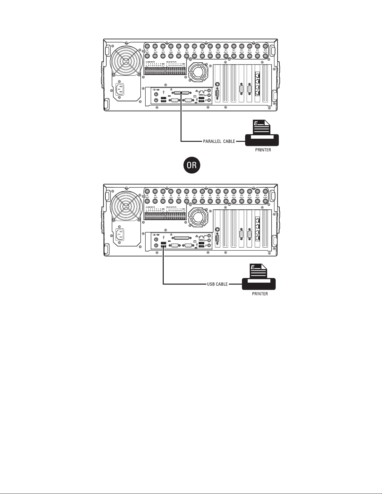
Figure 59. Printer Connection
58 C623M-C (3/05)
Page 59

PRINTER SOFTWARE SETUP
WARNING: Do not install any software that may have come with your printer on the DX8000. The DX8000’s operating system includes
built-in services designed to communicate with printers that exhibit the Designed for Microsoft Windows XP logo.
SETTING UP A LOCAL PLUG-AND-PLAY PRINTER
1. Make sure your printer is properly connected according to the instructions in the previous section.
2. Start the DX8000.
3. Wait while the system detects your printer and the Windows Add Printer Wizard begins.
4. If the Add Printer Wizard starts automatically, skip to step 13. If the Add Printer Wizard fails to start, turn the printer power off, wait
approximately fifteen seconds, and then turn the power on again. If, after a second attempt, the Add Printer Wizard still fails to start,
continue to step 5.
5. Log in to the DX8000 as an Administrator level user.
6. Exit the DX8000 application and return to the Windows operating system. For more information, refer to Exiting to Windows Operating
System on page 27.
7. Click Start > Settings > Printers. The Printer Setup window opens. Double-click Add Printer.
Figure 60. Printer Setup Window (Plug-and-Play)
C623M-C (3/05) 59
Page 60

8. The Add Printer Wizard dialog box opens. Click Next.
Figure 61. Add Printer Wizard Dialog Box (Plug-and-Play)
The Local or Network Printer dialog box opens.
Figure 62. Local or Network Printer Dialog Box (Plug-and-Play)
9. Select the “Local printer” option button.
10. Select the “Automatically detect and install my Plug and Play printer” check box if it is not already selected.
11. Click Next and wait while the DX8000 finds and initiates your printer.
60 C623M-C (3/05)
Page 61

12. The New Printer Detection dialog box opens. Select the Yes radio button, if it is not already selected, to print a test page. Then click Next.
Figure 63. Finding and Initializing a Plug-and-Play Printer
13. The Finish dialog box opens. Click Finish.
Figure 64. Completing the Add Printer Wizard Dialog Box (Plug-and-Play)
C623M-C (3/05) 61
Page 62
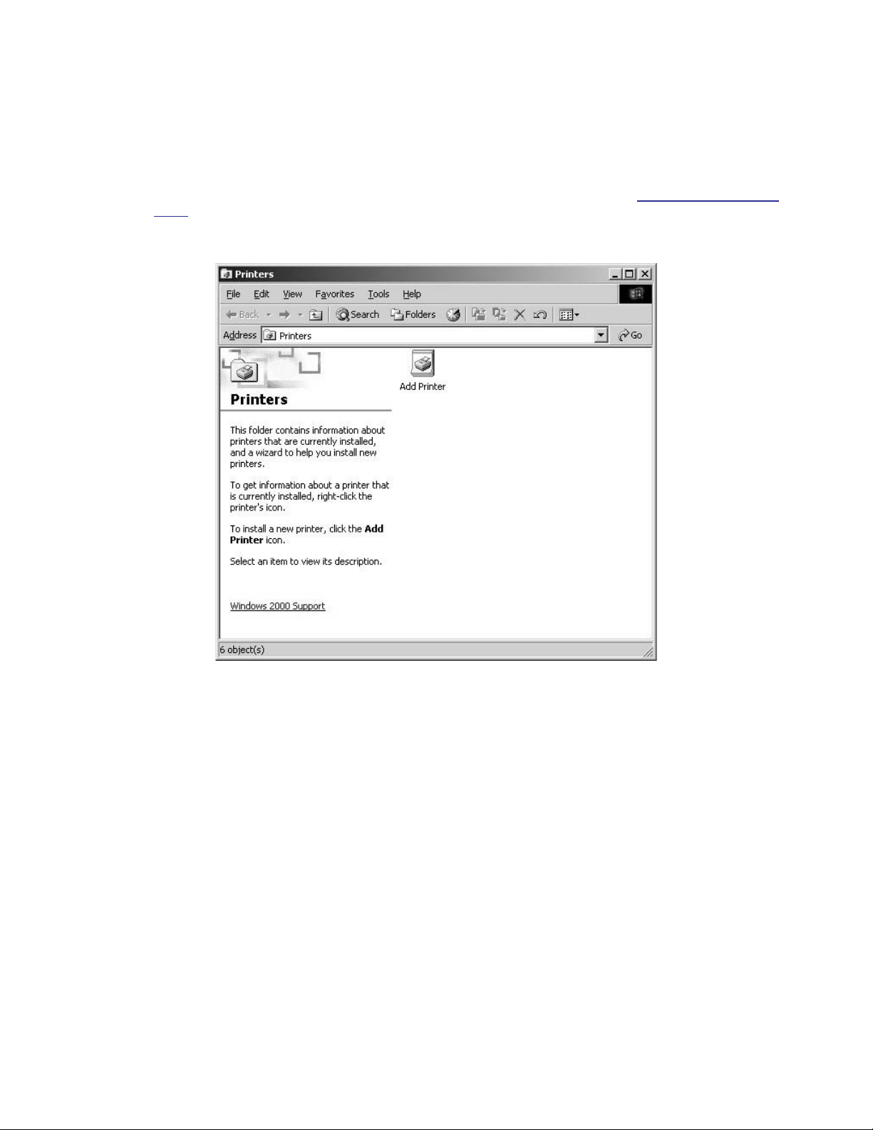
SETTING UP A LOCAL PRINTER THAT IS NOT PLUG-AND-PLAY
To set up a local printer that is not plug-and-play:
1. Start the DX8000.
2. Log in as an Administrator level user.
3. Exit the DX8000 application and return to the Windows operating system. For more information, refer to Exiting to Windows Operating
System on page 27.
4. Click Start > Settings > Printers. The Printer window opens. Double-click Add Printer.
Figure 65. Printer Window (Not Plug-and-Play)
62 C623M-C (3/05)
Page 63
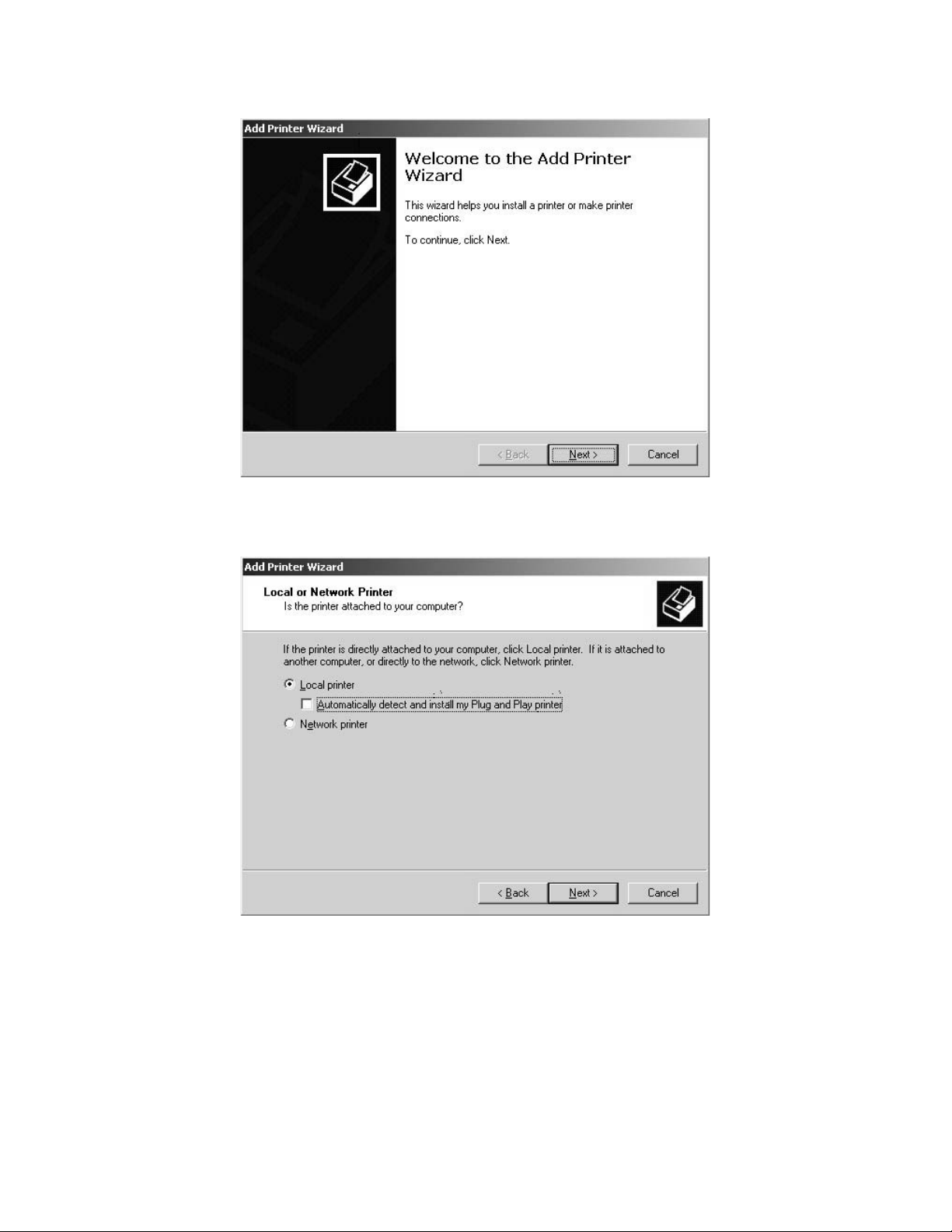
5. Welcome to the Add Printer Wizard dialog box opens. Click Next.
Figure 66. Welcome to the Add Printer Dialog Box
6. The Local or Network Printer dialog box opens. Select the “Local printer” radio button, and then click Next.
Figure 67. Local or Network Printer Dialog Box (Not Plug-and-Play)
C623M-C (3/05) 63
Page 64

7. The Select the Printer Port dialog box opens.
Figure 68. Select the Printer Port Dialog Box (Not Plug-and-Play)
8. Select the “Use the following port” radio button if it is not already selected.
9. Select LPT1.
10. Click Next.
64 C623M-C (3/05)
Page 65
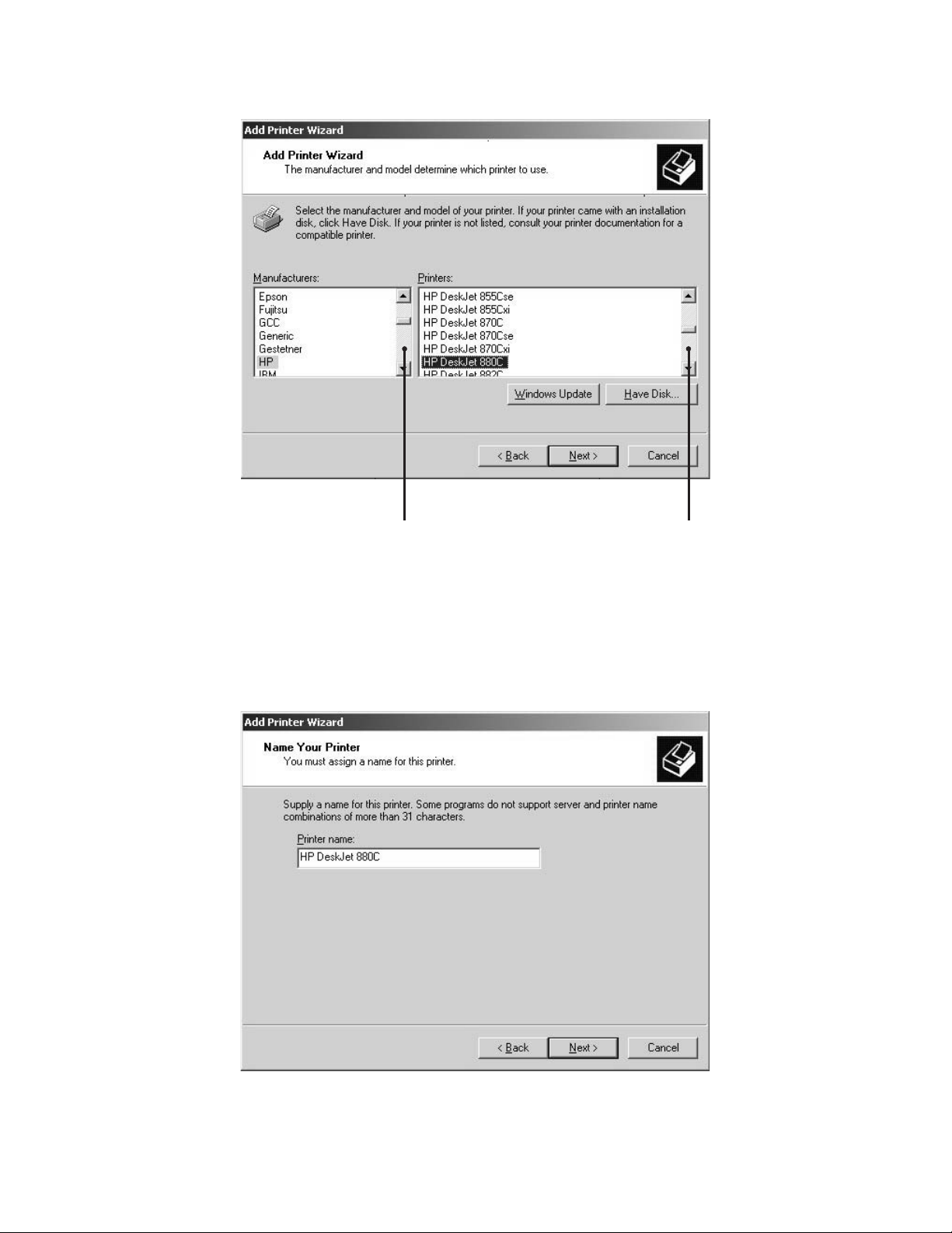
11. The Add Printer Wizard dialog box opens.
Figure 69. Add Printer Wizard Dialog Box (Not Plug-and-Play)
12. Scroll through the list of manufacturers and select the appropriate make.
13. Scroll through the list of printers and select the appropriate model.
14. Click Next.
15. The Name Your Printer dialog box opens. Click Next.
Figure 70. Name Your Printer Dialog Box (Not Plug-and-Play)
C623M-C (3/05) 65
Page 66

16. The Printer Sharing dialog box opens. Select the “Do not share this printer” radio button if it is not already selected, and then click Next.
Figure 71. Printer Sharing Dialog Box (Not Plug-and-Play)
17. The Print Test Page dialog box opens. Select the Yes radio button, if it is not already selected, to print a test page. Then click Next.
Figure 72. Print Test Page Dialog Box (Not Plug-and-Play)
66 C623M-C (3/05)
Page 67
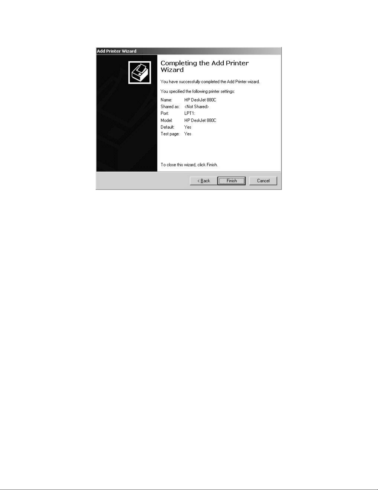
18. The Completing the Add Printer Wizard dialog box opens. Click Finish.
Figure 73. Completing the Add Printer Wizard Dialog Box (Not Plug-and-Play)
C623M-C (3/05) 67
Page 68

SETTING UP A NETWORK PRINTER
IMPORTANT: Consult your network administrator for assistance on locating and setting up an available network printer.
1. Start the DX8000.
2. Log in as an Administrator level user.
3. Exit the DX8000 application and return to the Windows operating system. For more information, refer to Exiting to Windows Operating
System on page 27.
4. Click Start > Settings > Printers. The Printer Setup window opens. Double-click Add Printer.
Figure 74. Printer Window (Network)
68 C623M-C (3/05)
Page 69

5. The Welcome to the Add Printer Wizard dialog box opens. Click Next.
Figure 75. Welcome to the Add Printer Wizard Dialog Box (Network)
6. The Local or Network Printer dialog box opens. Select the “Network printer” radio button, and then click Next.
Figure 76. Local or Network Printer Dialog Box (Network)
C623M-C (3/05) 69
Page 70

7. The Locate Your Printer dialog box opens. Leave the Name text box blank and then click Next.
Figure 77. Locate Your Printer Dialog Box (Network)
8. The Browse for Printer dialog box opens.
Figure 78. Browse For Printer Dialog Box (Network)
9. Select the desired printer from the list, and then click Next.
NOTES:
• Depending on your network setup, you may have to search through a hierarchical list of network resources to find the appropriate
printer. It may be necessary to double-click objects in the list to open each branch of the resource hierarchy.
• If the printer driver software is not already installed on your DX8000, you will be prompted to download it.
If prompted, click Yes to begin the driver download and follow any remaining instructions in the Add Printer Wizard.
70 C623M-C (3/05)
Page 71

10. The New Printer Detection dialog box opens. Select the Yes radio button, if it is not already selected, to print a test page. Then click Next.
Figure 79. New Printer Detection Dialog Box (Network)
11. The Completing the Add Printer Wizard dialog box opens. Click Finish.
Figure 80. Completing the Add Printer Wizard Dialog Box
C623M-C (3/05) 71
Page 72

Appendix B: Connecting Optional DX8000-MUX8/16 Display Card
The optional DX8000-MUX8/16 display card provides two additional analog video outputs. The display card includes one output that mirrors the
VGA display and one output that is user-definable. The card uses standard BNC-type coaxial connectors.
To attach one or two analog monitors to the display card, connect each monitor to the card using standard coaxial video cable. Refer to Table A
on page 18 for video coaxial cable requirements.
1. Connect an analog monitor to video output one. The output of this port mirrors the VGA output.
2. Connect a second analog monitor to video output two. This port serves as a user-configurable spot monitor output.
3. Refer to the Operation/Programming manual for instructions on configuring the DX8000-MUX8/16 output ports in software.
\
IN1 IN2 IN3 IN4 IN5 IN6 IN7 IN8 IN9 IN10 IN11 IN12 IN13 IN14 IN15 IN16
ALARMINPUTS RELAY OUTPUTS
12245678GND
91011121314151
Figure 81. DX8000-MUX8/16 Display Card Connections
1 2245678GND
6
910111213141516
CRT
OUT16OUT15OUT14OUT13OUT12OUT11OUT10OUT9OUT8OUT7OUT6OUT5OUT4OUT3OUT2OUT1
72 C623M-C (3/05)
Page 73
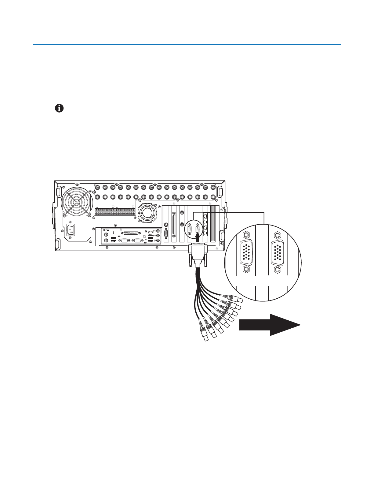
Appendix C: Connecting the Optional DX8000-AUD Audio Option
The DX8000 supports audio recording capabilities with the installation of the DX8000-AUD audio expansion option. Audio inputs correspond to
video inputs; therefore, an eight-channel DX8000 Series DVR can accept eight audio inputs and a sixteen-channel DVR can accept sixteen audio
inputs. Audio and video inputs are configured in a one-to-one relationship. For example, audio input seven corresponds to video channel seven.
The DX8000 accepts up to 16 individual monaural audio inputs. Each input is designed to receive a line-level, analog audio signal that is sampled
at a rate of 48 kHz (16 bits) by the DX8000-AUD’s digital analog converters (DAC). To minimize the amount of storage required to store audio data,
the audio stream is down-sampled to 8 kHz (8 bits) for storage and playback.
IMPORTANT: Before using the audio recording features of the DX8000, consult the applicable laws regarding audio surveillance recording
for your location.
SETTING UP AUDIO INPUTS
Audio input to the DX8000 is provided through an audio cable consisting of eight RCA connectors wired to a 15-pin D-sub breakout connector.
The D-sub connector plugs into the rear panel of the DVR. Depending on your system’s configuration, either one or two breakout cables will be
required to connect the DVR to an audio system.
1. Connect the 15-pin D-sub audio breakout connector to the rear of the DVR to provide eight individual audio inputs. Refer to Figure 82.
IN1 IN2 IN3 IN4 IN5 IN6 IN7 IN8 IN9 IN10 IN11 IN12 IN13 IN14 IN15 IN16
ALARMINPUTS RELAY OUTPUTS
12245678GND
91011121314151
1 2245678GND
6
910111213141516
CRT
Figure 82. Audio Connector Installation
OUT16OUT15OUT14OUT13OUT12OUT11OUT10OUT9OUT8OUT7OUT6OUT5OUT4OUT3OUT2OUT1
OPTIONAL AUDIO INPUTS 1-8
FOR 8 AND 16 CHANNEL DVRS.
OPTIONAL AUDIO INPUTS 9-16
FOR 16 CHANNEL DVRS.
AUDIO
(PREAMP)
C623M-C (3/05) 73
Page 74

2. Connect each of the eight RCA-type audio connectors to a line-level (+4 dB) gain audio source. Refer to Figure 83.
IMPORTANT: The DX8000-AUD option accepts an unbalanced, line-level audio signal only. Line-level signaling requires a voltage
between -1 V and +1 V into an impedance of 1 kΩ or more. This means that the output of most microphones will be too low to function
when connected directly to the DX8000’s audio inputs. In most applications, a preamplifier such as the Louroe Electronics ASK-4® KIT #101
will be required to boost the signal of a microphone to a level that is acceptable for input into the DX8000.
3. Refer to the Operation/Programming manual for information on how to configure the optional audio recording features of the DX8000.
TO DX8000
MICROPHONES
PIN 4
PIN 2
PIN 1
PIN 3
PIN 6
PIN 5
PREAMPLIFIERS
Figure 83. Audio Input Configuration Example
PIN 6
PIN 7
PIN 8
PIN 8
PIN 7
PIN 5
PIN 3
PIN 4
PIN 2
PIN 1
PREAMPLIFIERS
MICROPHONES
1
2
3
4
5
6
7
CABLE CONNECTORDVR CONNECTOR
8
Figure 84. Audio Input Cable Pinouts
74 C623M-C (3/05)
Page 75

SETTING UP AUDIO OUTPUT
CRT
The DX8000 delivers a line-level monaural signal through a standard 0.125-inch phone jack on the rear panel of the DVR. It is recommended that
the audio output of the DX8000 be connected to an amplifier in order to boost the output signal to a level that is sufficient to drive a speaker.
Figure 85 illustrates an example of an audio output configuration.
NOTE: Some speaker systems integrate both amplifiers and speakers in a single unit. Such a system can be connected directly to the
audio output of the DX8000 without the need for external amplification.
1. Connect the audio output of the DX8000 to an audio amplifier.
NOTE: Use an audio cable with a 0.125-inch miniature male phone plug on one end to connect to the audio output of the DX8000. Ensure
that the opposite end of the cable has the appropriate connectors for connection to your amplifier.
2. Connect the audio amplifier to a speaker.
SPEAKER
ALARMINPUTS RELAY OUTPUTS
1 2245678GND
910111213141516
AUDIO AMPLIFIER
IN1 IN2 IN3 IN4 IN5 IN6 IN7 IN8 IN9 IN10 IN11 IN12 IN13 IN14 IN15 IN16
1 2245678GND
910111213141516
CRT
OUT16OUT15OUT14OUT13OUT12OUT11OUT10OUT9OUT8OUT7OUT6OUT5OUT4OUT3OUT2OUT1
CRT
MINI MALE PHONE PLUG
Figure 85. Audio Output Configuration Example
C623M-C (3/05) 75
Page 76

Appendix D: Connecting an Uninterruptible Power Supply (UPS)
If uninterrupted operation is desired and the power grid cannot provide adequate uptime, it is highly recommended that each DX8000 Series DVR
be connected to a UPS device (not supplied). A UPS device will supply a limited amount of battery backup power in the event of a power failure.
Each UPS device should be configured to shut down its corresponding DVR safely during an extended period on battery power.
IMPORTANT: Only those UPS devices that exhibit the Designed for Microsoft Windows XP logo and are listed on the Windows 2000
Hardware Compatibility List are approved for use with the DX8000 Series DVR.
WARNING: Do not install on the DX8000 any power management software that may come with your UPS device. The DX8000’s operating
system includes built-in services designed to communicate with UPS devices that exhibit the Designed for Microsoft Windows XP logo.
NOTE: The following instructions are meant as a general guide for connecting a UPS device to the DX8000 Series DVR. The example
below illustrates the installation of an American Power Conversion UPS. This guide is not intended as a representation of how to install
every possible make and model of UPS device. Follow the directions that came with your UPS device to ensure that the installation process
is completed properly.
UPS TO DVR COMMUNICATION AND POWER CONNECTIONS
1. Shut down the DX8000. Refer to Shutting Down on page 26 for instructions.
2. Connect the UPS to the DX8000 using a standard USB cable.
3. Connect the other end of the USB cable to one of the four USB 2.0 ports on the back panel of the DVR.
4. Connect the power cord of the UPS to a standard wall socket.
5. Connect the power cord of the DX8000 to one of the power outlets on the UPS.
6. Turn the UPS device power switch on.
7. Turn the DX8000 power switch on.
IN1 IN2 IN3 IN4 IN5 IN6 IN7 IN8 IN9 IN10 IN11 IN12 IN13 IN14 IN15 IN16
POWER
CONNECTION
UPS
RS-232
ALARMINPUTS RELAYOUTPUTS
12245678GND
910111213141516
USB CABLE
12245678GND
910111213141516
OUT16OUT15OUT14OUT13OUT12OUT11OUT10OUT9OUT8OUT7OUT6OUT5OUT4OUT3OUT2OUT1
CRT
POWER
CONNECTION
Figure 86. UPS to DX8000 Connections
76 C623M-C (3/05)
Page 77

SOFTWARE SETUP FOR A USB CONNECTED UPS DEVICE
1. Log in as an Administrator level user if you are not already.
2. Exit the DX8000 application and return to Windows operating system (refer to Exiting to Windows Operating System
3. Click Start > Settings > Control Panel. The Control Panel opens.
Figure 87. Control Panel Window with Power Options Selected
4. Double-click Power Options. The Power Options Properties dialog box opens.
on page 27).
C623M-C (3/05) 77
Page 78

5. Click the Alarms tab.
6. Adjust the Critical Battery Alarm slider to the desired power level threshold.
NOTE: The slider can be adjusted to signal an alarm when UPS battery power falls below the level you select. It is suggested that you set
the value that provides at least five minutes of power in order to shut down the DX8000 safely. Refer to the documentation supplied with
your UPS to determine the percentage value that will provide at least five minutes of reserve power.
7. Click Alarm Action under “Critical battery alarm.” The Power Options Properties dialog box opens.
Figure 88. Power Options Properties Dialog Box
78 C623M-C (3/05)
Page 79
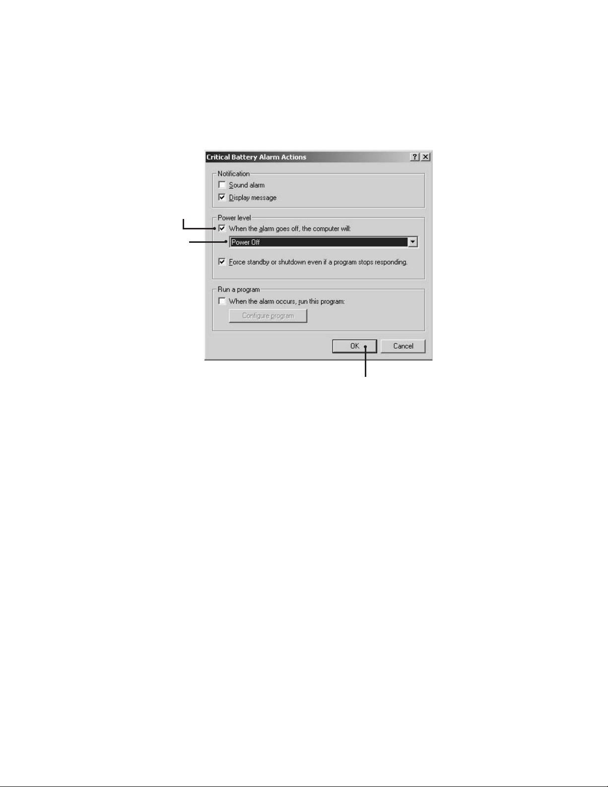
8. Select the “When the alarm goes off, the computer will:” check box under “Power level.”
9. Select Power Off from the drop-down list.
10. Click OK.
11. Click Apply.
12. Click OK.
Figure 89. Critical Battery Alarm Actions Dialog Box
C623M-C (3/05) 79
Page 80

Appendix E: External Storage Expansion Using DX9200HDDI
BASIC INSTALLATION
The DX9200HDDI can increase the DX8000’s storage capacity by up to 3.2 TB. The external IDE RAID is connected to the DX8000’s optional SCSI
interface by a 50-pin to 68-pin SCSI cable, included with the DX9200HDDI. The DX9200HDDI option is available for DX8008-080 and DX8016-080
systems that are preconfigured at the factory.
IMPORTANT:
• The DX9200HDDI can be used for either offline backup storage or real-time video storage. When used as a real-time storage device,
the frame rates of each channel on the DX8000 must be set at less than or equal to 24 images per second (ips) for 16-channel DVRs
and up to 30 ips for 8-channel DVRs. Setting the frame rate above 24 ips for a 16-channel DVR will result in skipped frames and
significant performance degradation.*
• To connect the DX9200HDDI to the DX8000, the optional DX8000-ISCI internal SCSI interface must be installed.
• Make sure HDDI power is turned on first and then turn power on to the DX8000.
1. Connect either one or two DX8000 DVRs to a single DX9200HDDI with a standard 50-pin to 68-pin SCSI cable.
DX8000
DX8000
DX8000
IN1 IN2 IN3 IN4 IN5 IN6 IN7 IN8 IN9 IN10 IN11 IN12 IN13 IN14 IN15 IN16
ALARMINPUTS RELAYOUTPUTS
1 2245678GND
1 2245678GND
910111213141516
910111213141516
CRT
Figure 90. Single DX8000 to DX9200HDDI SCSI Connection
IN1 IN2 IN3 IN4 IN5 IN6 IN7 IN8 IN9 IN10 IN11 IN12 IN13 IN14 IN15 IN16
ALARMINPUTS RELAYOUTPUTS
1 2245678GND
1 2245678GND
910111213141516
910111213141516
CRT
IN1 IN2 IN3 IN4 IN5 IN6 IN7 IN8 IN9 IN10 IN11 IN12 IN13 IN14 IN15 IN16
ALARMINPUTS RELAYOUTPUTS
1 2245678GND
1 2245678GND
910111213141516
910111213141516
SCSI
OUT16OUT15OUT14OUT13OUT12OUT11OUT10OUT9OUT8OUT7OUT6OUT5OUT4OUT3OUT2OUT1
DX9200HDDI
SCSI
OUT16OUT15OUT14OUT13OUT12OUT11OUT10OUT9OUT8OUT7OUT6OUT5OUT4OUT3OUT2OUT1
SCSI
OUT16OUT15OUT14OUT13OUT12OUT11OUT10OUT9OUT8OUT7OUT6OUT5OUT4OUT3OUT2OUT1
DX9200HDDI
CRT
Figure 91. Dual DX8000 to DX9200HDDI SCSI Connection
*The test case used in evaluating the DX8000’s ability to operate in real-time with the DX9200HHDI storage array was conducted using a
16-channel DVR recording at 24 ips and 320 x 240 resolution.
80 C623M-C (3/05)
Page 81

2. Refer to the documentation that accompanies the DX9200HDDI for additional information on installing and operating the unit.
3. Return unit to service.
NOTE: Initialization of the DX9200HDDI’s RAID 5 array may take up to 24 hours. While the unit can be placed into service immediately,
system performance may suffer until array initialization is complete.
ADDITIONAL HARD DISK INSTALLATION
Refer to the documentation that accompanies the DX9200HDDI for instructions on how to install additional hard disk drives into the storage
array.
PREPARING THE DX8000 TO ACCESS NEWLY INSTALLED DRIVES
IMPORTANT: The following procedures should be performed only by users experienced in upgrading computer hardware and software.
Preparation Instructions for Storage Arrays up to 2.0 TB
The instructions below describe the sequence of steps required to prepare and allocate storage arrays up to 2.0 TB. To allocate storage beyond
2.0 TB, refer to Preparation Instructions for Storage Arrays Above 2.0 TB on page 84.
To allocate the new storage:
1. To exit the DX8000 application if it is running, and log into the Windows operating system.
a. Go to File > Exit.
b. Select Exit to Windows. The Shut down dialog box opens.
c. Click OK.
Figure 92. Shut Down Dialog Box
The Log On to Windows dialog box opens.
2. Enter the Windows password and click OK. The system logs you into the Windows operating system.
3. Go to Start > Programs > Allocreset.exe.
WARNING: The Allocreset.exe program will reset the DX8000’s storage allocation tables. This program should be executed only when
increasing the storage capacity of the DX9200HDDI storage array.
4. The Allocation Management dialog box opens.
Figure 93. Allocation Management Dialog Box
5. Click Re-Allocate.
6. Go to Start > Shutdown > Restart to reboot the DX8000.
7. After the system has been rebooted, the PDB Initialize dialog box opens. Before new drives can be used to store video data, each drive
must be made compatible with the DX8000’s Pelco proprietary database (PDB) file structure.
C623M-C (3/05) 81
Page 82

Follow the steps below after the PDB Initialize dialog box opens, and perform the following steps to finalize storage setup:
a. Click the plus (+) sign next to the blue box—the one that reads, “Space on one or more hard disk drives has not yet been allocated to
the PDB database.”
Figure 94. Opening List of Drives
b. For each drive listed, click the Not Used button. A drop-down menu appears. There may be more than one drive listed, as shown in the
figure below.
Figure 95. Opening Drive Options Menu
82 C623M-C (3/05)
Page 83

c. For each drive listed, select the Allocation option from the drop-down menu.
Figure 96. Selecting Allocation Option for Each Drive
d. Click Begin Allocation.
Figure 97. Initializing Drive Allocation
e. The following warning is displayed. Click Yes.
Figure 98. Format Warning Dialog Box
f. Wait while the DX8000 prepares the newly installed drives for video storage. You will see the following progress bar while the
formatting is underway.
Figure 99. PDB Database Creation Progress Bar
8. After the storage allocation procedure is complete, the DX8000 will reboot automatically and will be ready to resume service.
C623M-C (3/05) 83
Page 84

Preparation Instructions for Storage Arrays Above 2.0 TB
To initialize storage beyond 2.0 TB:
1. To exit the DX8000 application if it is running, and log into the Windows operating system.
a. Go to File > Exit.
b. Select Exit to Windows. The Shut Down dialog box opens.
c. Click OK.
Figure 100. Shut Down Dialog Box
The Log On to Windows dialog box opens.
2. Enter the WIndows password and click OK. The system logs you into the Windows operating system.
3. Right-click the Start button. The Start button shortcut menu opens.
Figure 101. Start Button Shortcut Menu
4. Select the Explore option. The Start Menu opens.
Figure 102. My Computer Quick Menu
84 C623M-C (3/05)
Page 85

5. Right-click My Computer.
6. Select Manage. The Computer Management window opens.
Figure 103. Computer Management Window
7. Select the Disk Management folder. The Write Signature and Upgrade Disk Wizard opens.
Figure 104. Write Signature and Upgrade Disk Wizard Dialog Box
8. Click Cancel.
9. Right-click in the Unallocated Space block. A shortcut menu opens.
C623M-C (3/05) 85
Page 86

Figure 105. Unallocated Space Shortcut Menu
10. Select Create Partition. The Create Partition Wizard dialog box opens.
Figure 106. Create Partition Wizard Dialog Box
11. Click Next. The Select Partition Type screen opens.
86 C623M-C (3/05)
Page 87

Figure 107. Select Partition Type Screen Dialog Box
12. Select Primary Partition and then click Next. The Specify Partition Size dialog box opens.
Figure 108. Specify Partition Size Screen
13. Click Next. The Assign Drive Letter or Path dialog box opens.
NOTE: The partition size value is set to 100% by default. Do not change the partition size value.
C623M-C (3/05) 87
Page 88

Figure 109. Assign Drive Letter or Path Dialog Box
14. Click Next. The Format Partition dialog box opens.
Figure 110. Format Partition Dialog Box
15. Select the Perform a Quick Format check box and then click Next.
IMPORTANT: Make sure the Perform a Quick Format option is selected before clicking the Next button. Failure to select the Quick Format
option will result in an unnecessarily long formatting time.
88 C623M-C (3/05)
Page 89

16. Click Finish. The new drive appears in the device list.
Figure 111. Completing the Create Partition Wizard Dialog Box
17. Right-click the new drive from the device list. A shortchut menu opens.
Figure 112. Drive Shortcut Menu
18. Select the Mark Partition Active option.
C623M-C (3/05) 89
Page 90
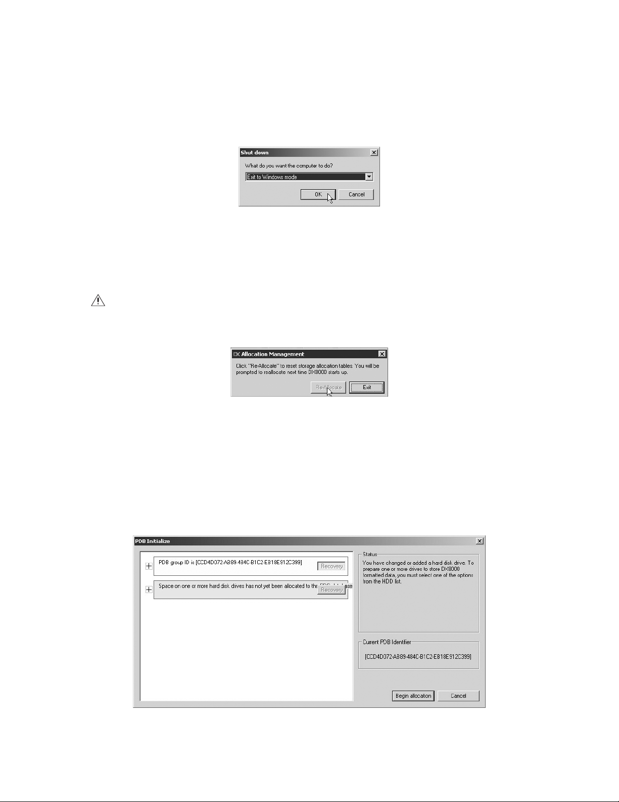
To allocate the new storage:
1. To exit the DX8000 application if it is running, and log into the Windows operating system.
a. Go to File > Exit.
b. Select Exit to Windows.
c. Click OK.
Figure 113. Exit to Windows Dialog Box
The Log On to Windows dialog box opens.
2. Enter the Windows password and click OK. The system logs you into the Windows operating system.
3. Go to Start > Programs > Allocreset.exe.
WARNING: The Allocreset.exe program will reset the DX8000’s storage allocation tables. This program should be executed only when
increasing the storage capacity of the DX9200HDDI storage array.
4. The Allocation Management dialog box opens.
Figure 114. Allocation Management Dialog Box
5. Click Re-Allocate.
6. Go to Start > Shutdown > Restart to reboot the DX8000.
7. After the system has been rebooted, the PDB Initialize dialog box opens. Before new drives can be used to store video data, each drive
must be made compatible with the DX8000’s Pelco proprietary database (PDB) file structure. Follow the steps below after the PDB Initialize
dialog box opens, and perform the following steps to finalize storage setup:
a. Click the plus (+) sign next to the blue box—the one that reads, “Space on one or more hard disk drives has not yet been allocated to
the PDB database.”
Figure 115. Opening List of Drives
90 C623M-C (3/05)
Page 91

b. For each drive listed, click the Not Used button. A drop-down menu appears. There may be more than one drive listed, as shown in the
figure below.
Figure 116. Opening Drive Options Menu
c. For each drive listed, select the Allocation option from the drop-down menu.
Figure 117. Selecting Allocation Option for Each Drive
d. Click Begin Allocation.
Figure 118. Initializing Drive Allocation
C623M-C (3/05) 91
Page 92

e. The following warning is displayed. Click Yes.
Figure 119. Format Warning Dialog Box
f. Wait while the DX8000 prepares the newly installed drives for video storage. You will see the following progress bar while the
formatting is underway.
Figure 120. PDB Database Creation Progress Bar
8. After the storage allocation procedure is complete, the DX8000 will reboot automatically and the unit will be ready to resume service.
92 C623M-C (3/05)
Page 93

Specifications
ELECTRICAL/VIDEO
Input Voltage: 100-240 VAC, 50/60 Hz, autoranging
Signal System: NTSC/PAL
Operating System: Windows 2000 and Service Pack 4
Resolution
NTSC: 720 x 480 pixels
PAL: 720 x 576 pixels
Compression: Pelco proprietary based on H.263
Video Inputs: 8/16 (looping with automatic termination)
VGA Outputs: 1
Analog Video Outputs (Optional) 2
Relay Output Terminals 8/16 (user selectable, N.O./N.C.)
Relay Contact Ratings*
Rated (Resistive) Load 0.5 A at 120 VAC or 1 A at 24 VDC
Programmable Analog Display Output (Optional):2
Recording Resolutions: NTSC
Remote Administration: Full remote control via TCP/IP network
Total Recording Rate: Up to 480 images per second (NTSC)
PAL
320 x 240 352 x 288
640 x 240 704 x 288
640 x 480 704 x 576
720 x 240 720 x 288
720 x 480 720 x 576
Up to 400 images per second (PAL)
*Relays are grounded.
MECHANICAL
Connectors
BNC: Video inputs and outputs
6-pin mini-DIN: PS/2 mouse and keyboard
DB9: COM 1 and COM 2 (disabled)
DB15: Monitor port (SVGA) and optional audio input ports
RJ-45: Ethernet port (100 BaseT) and RS-485/RS-422 ports
0.125-Inch Phone Jack: Audio output
S-Video: S-Video analog output (disabled)
USB: Six High-Speed USB 2.0 ports (2 in front, 4 in rear)
ENVIRONMENTAL
Operating Temperature: 50° to 95°F (10° to 35°C)
Relative Humidity: Maximum 80%, noncondensing
GENERAL
Dimensions
Desktop: 7 (H) x 17 (W) x 19.9 (D) inches (17.78 x 43.18 x 50.55 cm)
Rack Mount: 7.0 (H) x 19.0 (W) x 22 (D) inches (17.78 x 48.26 x 55.88 cm)
Unit Weight: 44 lb (20 kg) maximum (fully equipped, 16 channel unit)
Shipping Weight: 65 lb (43 kg) maximum (fully equipped, 16 channel unit)
(Design and product specifications subject to change without notice.)
C623M-C (3/05) 93
Page 94

94 C623M-C (3/05)
Page 95

PRODUCT WARRANTY AND RETURN INFORMATION
WARRANTY
Pelco will repair or replace, without charge, any merchandise proved defective in
material or workmanship for a period of one year after the date of shipment.
Exceptions to this warranty are as noted below:
• Five years on FT/FR8000 Series fiber optic products and the following fixed
camera models: CC3701H-2, CC3701H-2X, CC3751H-2, CC3651H-2X, MC3651H2, and CC3651H-2X.
• Three years on all other fixed camera models (including Camclosure® Integrated
Camera Systems) and Genex® Series (multiplexers, server, and keyboard).
•Two years on all standard motorized or fixed focal length lenses.
•Two years on Legacy®, CM6700/CM6800/CM8500/CM9500/CM9700 Series
Matrix, DF5 and DF8 Series Fixed Dome products.
•Two years on Spectra®, Esprit®, and PS20 Scanners, including when used in
continuous motion applications.
•Two years on Esprit® and WW5700 Series window wiper (excluding wiper
blades).
• Eighteen months on DX Series digital video recorders and NVR300 Series
network video recorders.
• One year (except video heads) on video cassette recorders (VCRs). Video heads
will be covered for a period of six months.
• Six months on all pan and tilts, scanners or preset lenses used in continuous
motion applications (that is, preset scan, tour and auto scan modes).
Pelco will warrant all replacement parts and repairs for 90 days from the date of
Pelco shipment. All goods requiring warranty repair shall be sent freight prepaid to
Pelco, Clovis, California. Repairs made necessary by reason of misuse, alteration,
normal wear, or accident are not covered under this warranty.
Pelco assumes no risk and shall be subject to no liability for damages or loss resulting from the specific use or application made of the Products. Pelco’s liability for
any claim, whether based on breach of contract, negligence, infringement of any
rights of any party or product liability, relating to the Products shall not exceed the
price paid by the Dealer to Pelco for such Products. In no event will Pelco be liable
for any special, incidental or consequential damages (including loss of use, loss of
profit and claims of third parties) however caused, whether by the negligence of
Pelco or otherwise.
The above warranty provides the Dealer with specific legal rights. The Dealer may
also have additional rights, which are subject to variation from state to state.
If a warranty repair is required, the Dealer must contact Pelco at (800) 289-9100 or
(559) 292-1981 to obtain a Repair Authorization number (RA), and provide the
following information:
1. Model and serial number
2. Date of shipment, P.O. number, Sales Order number, or Pelco invoice number
3. Details of the defect or problem
If there is a dispute regarding the warranty of a product which does not fall under
the warranty conditions stated above, please include a written explanation with
the product when returned.
Method of return shipment shall be the same or equal to the method by which the
item was received by Pelco.
RETURNS
In order to expedite parts returned to the factory for repair or credit, please call the
factory at (800) 289-9100 or (559) 292-1981 to obtain an authorization number (CA
number if returned for credit, and RA number if returned for repair).
All merchandise returned for credit may be subject to a 20% restocking and refurbishing charge.
Goods returned for repair or credit should be clearly identified with the assigned CA
or RA number and freight should be prepaid. Ship to the appropriate address below.
If you are located within the continental U.S., Alaska, Hawaii or Puerto Rico, send
goods to:
Service Department
Pelco
3500 Pelco Way
Clovis, CA 93612-5699
If you are located outside the continental U.S., Alaska, Hawaii or Puerto Rico and
are instructed to return goods to the USA, you may do one of the following:
If the goods are to be sent by a COURIER SERVICE, send the goods to:
Pelco
3500 Pelco Way
Clovis, CA 93612-5699 USA
If the goods are to be sent by a FREIGHT FORWARDER, send the goods to:
Pelco c/o Expeditors
473 Eccles Avenue
South San Francisco, CA 94080 USA
Phone: 650-737-1700
Fax: 650-737-0933
Microsoft, Windows, DirectX, ActiveSync, and ActiveX are registered trademarks of Microsoft Corporation in the United States and/or other countries.
Pelco, the Pelco Logo, Spectra, Genex, Legacy, Esprit, Camclosure, and Coaxitron are registered trademarks of Pelco.
Intel, Pentium, and XScale are registered trademarks of Intel Corporation.
Netscape is a registered trademark of the Netscape Communications Corporation.
StorageWorks is a registered trademark of Compaq Information Technologies Groupl.
ASK-4 is a registered trademark of Louroe Electronics.
Adobe and Acrobat are registered trademarks of Adobe Systems Incorporated.
Spectra III is a trademark of Pelco.
© Copyright 2005, Pelco. All rights reserved.
REVISION HISTORY
Manual # Date Comments
C623M 2/04 Original version.
C623M-A 3/04 Incorporated changes from C623M-Adden and added new client installation procedures.
C623M-B 12/04 Added Appendix F: External Storage Expansion Using DX9200HDDI.
C623M-C 3/05 Removed Appendix D: Connecting an External Tape Backup Unit. Refers user to consult the Important Security Information for System Administrators guide
for information on using Ctrl+Alt+Del and the DX8000 default password.
Page 96

®
Worldwide Headquarters
3500 Pelco Way
Clovis, California 93612 USA
USA & Canada
Tel: 800/289-9100
Fax: 800/289-9150
International
Tel: 1-559/292-1981
Fax: 1-559/348-1120
www.pelco.com
ISO9001
United States | Canada | United Kingdom | The Netherlands | Singapore | Spain | Scandinavia | France | Middle East
 Loading...