

Page 1
OPERATION/PROGRAMMING
DX7100 Series
®
Digital Video Recorder
C642M (11/03)
Page 2

CONTENTS
Section Page
GETTING STARTED . . . . . . . . . . . . . . . . . . . . . . . . . . . . . . . . . . . . . . . . . . . . . . . . . . . . . . . . . . . . . . . . . . . . . . . . . . . . . . . . . . . . . . . . . . . . . . . . . . . . . . . 5
DISPLAY MODE . . . . . . . . . . . . . . . . . . . . . . . . . . . . . . . . . . . . . . . . . . . . . . . . . . . . . . . . . . . . . . . . . . . . . . . . . . . . . . . . . . . . . . . . . . . . . . . . . . . . . . . . . 6
SYSTEM SETUP . . . . . . . . . . . . . . . . . . . . . . . . . . . . . . . . . . . . . . . . . . . . . . . . . . . . . . . . . . . . . . . . . . . . . . . . . . . . . . . . . . . . . . . . . . . . . . . . . . . . . . . . . 8
SYSTEM SETUP MENUS . . . . . . . . . . . . . . . . . . . . . . . . . . . . . . . . . . . . . . . . . . . . . . . . . . . . . . . . . . . . . . . . . . . . . . . . . . . . . . . . . . . . . . . . . . . . . . 8
CAMERA SETUP . . . . . . . . . . . . . . . . . . . . . . . . . . . . . . . . . . . . . . . . . . . . . . . . . . . . . . . . . . . . . . . . . . . . . . . . . . . . . . . . . . . . . . . . . . . . . . . . . . . . 9
HOW TO SET UP A CAMERA . . . . . . . . . . . . . . . . . . . . . . . . . . . . . . . . . . . . . . . . . . . . . . . . . . . . . . . . . . . . . . . . . . . . . . . . . . . . . . . . . . . . . . 9
COLOR SETUP . . . . . . . . . . . . . . . . . . . . . . . . . . . . . . . . . . . . . . . . . . . . . . . . . . . . . . . . . . . . . . . . . . . . . . . . . . . . . . . . . . . . . . . . . . . . . . . . . . . . . 10
SCHEDULE SETUP . . . . . . . . . . . . . . . . . . . . . . . . . . . . . . . . . . . . . . . . . . . . . . . . . . . . . . . . . . . . . . . . . . . . . . . . . . . . . . . . . . . . . . . . . . . . . . . . . . 11
SCHEDULING EXAMPLE . . . . . . . . . . . . . . . . . . . . . . . . . . . . . . . . . . . . . . . . . . . . . . . . . . . . . . . . . . . . . . . . . . . . . . . . . . . . . . . . . . . . . . . . . 13
SPEED SETUP . . . . . . . . . . . . . . . . . . . . . . . . . . . . . . . . . . . . . . . . . . . . . . . . . . . . . . . . . . . . . . . . . . . . . . . . . . . . . . . . . . . . . . . . . . . . . . . . . . . . . 15
NORMAL SPEED MENU . . . . . . . . . . . . . . . . . . . . . . . . . . . . . . . . . . . . . . . . . . . . . . . . . . . . . . . . . . . . . . . . . . . . . . . . . . . . . . . . . . . . . . . . . 15
MOTION SPEED MENU . . . . . . . . . . . . . . . . . . . . . . . . . . . . . . . . . . . . . . . . . . . . . . . . . . . . . . . . . . . . . . . . . . . . . . . . . . . . . . . . . . . . . . . . . 17
SENSOR SPEED MENU . . . . . . . . . . . . . . . . . . . . . . . . . . . . . . . . . . . . . . . . . . . . . . . . . . . . . . . . . . . . . . . . . . . . . . . . . . . . . . . . . . . . . . . . . 18
MOTION DETECTION SETUP . . . . . . . . . . . . . . . . . . . . . . . . . . . . . . . . . . . . . . . . . . . . . . . . . . . . . . . . . . . . . . . . . . . . . . . . . . . . . . . . . . . . . . . . . . 19
PASSWORD SETUP . . . . . . . . . . . . . . . . . . . . . . . . . . . . . . . . . . . . . . . . . . . . . . . . . . . . . . . . . . . . . . . . . . . . . . . . . . . . . . . . . . . . . . . . . . . . . . . . . 20
PAN AND TILT SETUP . . . . . . . . . . . . . . . . . . . . . . . . . . . . . . . . . . . . . . . . . . . . . . . . . . . . . . . . . . . . . . . . . . . . . . . . . . . . . . . . . . . . . . . . . . . . . . . 21
UPDATE PROGRAM . . . . . . . . . . . . . . . . . . . . . . . . . . . . . . . . . . . . . . . . . . . . . . . . . . . . . . . . . . . . . . . . . . . . . . . . . . . . . . . . . . . . . . . . . . . . . . . . . 22
IMPORT SYSTEM CONFIGURATION . . . . . . . . . . . . . . . . . . . . . . . . . . . . . . . . . . . . . . . . . . . . . . . . . . . . . . . . . . . . . . . . . . . . . . . . . . . . . . . . . . . . 22
EXPORT SYSTEM CONFIGURATION . . . . . . . . . . . . . . . . . . . . . . . . . . . . . . . . . . . . . . . . . . . . . . . . . . . . . . . . . . . . . . . . . . . . . . . . . . . . . . . . . . . . 22
QUIT TO EXPLORER . . . . . . . . . . . . . . . . . . . . . . . . . . . . . . . . . . . . . . . . . . . . . . . . . . . . . . . . . . . . . . . . . . . . . . . . . . . . . . . . . . . . . . . . . . . . . . . . . 22
HOW TO OPERATE PTZ. . . . . . . . . . . . . . . . . . . . . . . . . . . . . . . . . . . . . . . . . . . . . . . . . . . . . . . . . . . . . . . . . . . . . . . . . . . . . . . . . . . . . . . . . . . . . . . . . . . 23
PTZ CONTROLS . . . . . . . . . . . . . . . . . . . . . . . . . . . . . . . . . . . . . . . . . . . . . . . . . . . . . . . . . . . . . . . . . . . . . . . . . . . . . . . . . . . . . . . . . . . . . . . . . . . . 24
PATTERNS . . . . . . . . . . . . . . . . . . . . . . . . . . . . . . . . . . . . . . . . . . . . . . . . . . . . . . . . . . . . . . . . . . . . . . . . . . . . . . . . . . . . . . . . . . . . . . . . . . . . . . . . 25
HOW TO PROGRAM A PATTERN . . . . . . . . . . . . . . . . . . . . . . . . . . . . . . . . . . . . . . . . . . . . . . . . . . . . . . . . . . . . . . . . . . . . . . . . . . . . . . . . . . 25
HOW TO CLEAR A PATTERN . . . . . . . . . . . . . . . . . . . . . . . . . . . . . . . . . . . . . . . . . . . . . . . . . . . . . . . . . . . . . . . . . . . . . . . . . . . . . . . . . . . . . 25
PRESETS . . . . . . . . . . . . . . . . . . . . . . . . . . . . . . . . . . . . . . . . . . . . . . . . . . . . . . . . . . . . . . . . . . . . . . . . . . . . . . . . . . . . . . . . . . . . . . . . . . . . . . . . . 25
HOW TO PROGRAM A PRESET . . . . . . . . . . . . . . . . . . . . . . . . . . . . . . . . . . . . . . . . . . . . . . . . . . . . . . . . . . . . . . . . . . . . . . . . . . . . . . . . . . . 25
HOW TO MOVE TO A PRESET . . . . . . . . . . . . . . . . . . . . . . . . . . . . . . . . . . . . . . . . . . . . . . . . . . . . . . . . . . . . . . . . . . . . . . . . . . . . . . . . . . . . 25
HOW TO CLEAR A PRESET . . . . . . . . . . . . . . . . . . . . . . . . . . . . . . . . . . . . . . . . . . . . . . . . . . . . . . . . . . . . . . . . . . . . . . . . . . . . . . . . . . . . . . . 25
PRESET TOURS . . . . . . . . . . . . . . . . . . . . . . . . . . . . . . . . . . . . . . . . . . . . . . . . . . . . . . . . . . . . . . . . . . . . . . . . . . . . . . . . . . . . . . . . . . . . . . . . . . . . 26
HOW TO PROGRAM A PRESET TOUR . . . . . . . . . . . . . . . . . . . . . . . . . . . . . . . . . . . . . . . . . . . . . . . . . . . . . . . . . . . . . . . . . . . . . . . . . . . . . . 26
HOW TO RUN A PRESET TOUR . . . . . . . . . . . . . . . . . . . . . . . . . . . . . . . . . . . . . . . . . . . . . . . . . . . . . . . . . . . . . . . . . . . . . . . . . . . . . . . . . . . 26
HOW TO CLEAR A PRESET TOUR . . . . . . . . . . . . . . . . . . . . . . . . . . . . . . . . . . . . . . . . . . . . . . . . . . . . . . . . . . . . . . . . . . . . . . . . . . . . . . . . . . 26
AUXILIARIES . . . . . . . . . . . . . . . . . . . . . . . . . . . . . . . . . . . . . . . . . . . . . . . . . . . . . . . . . . . . . . . . . . . . . . . . . . . . . . . . . . . . . . . . . . . . . . . . . . . . . . 26
SEARCH . . . . . . . . . . . . . . . . . . . . . . . . . . . . . . . . . . . . . . . . . . . . . . . . . . . . . . . . . . . . . . . . . . . . . . . . . . . . . . . . . . . . . . . . . . . . . . . . . . . . . . . . . . . . . . 27
DATE AND TIME SEARCH . . . . . . . . . . . . . . . . . . . . . . . . . . . . . . . . . . . . . . . . . . . . . . . . . . . . . . . . . . . . . . . . . . . . . . . . . . . . . . . . . . . . . . . . . . . . 29
SLIDER SEARCH . . . . . . . . . . . . . . . . . . . . . . . . . . . . . . . . . . . . . . . . . . . . . . . . . . . . . . . . . . . . . . . . . . . . . . . . . . . . . . . . . . . . . . . . . . . . . . . . . . . 30
INDEX SEARCH . . . . . . . . . . . . . . . . . . . . . . . . . . . . . . . . . . . . . . . . . . . . . . . . . . . . . . . . . . . . . . . . . . . . . . . . . . . . . . . . . . . . . . . . . . . . . . . . . . . . 31
HOW TO BACKUP VIDEO FILES . . . . . . . . . . . . . . . . . . . . . . . . . . . . . . . . . . . . . . . . . . . . . . . . . . . . . . . . . . . . . . . . . . . . . . . . . . . . . . . . . . . . . . . . . . . . 32
BACKUP WINDOW . . . . . . . . . . . . . . . . . . . . . . . . . . . . . . . . . . . . . . . . . . . . . . . . . . . . . . . . . . . . . . . . . . . . . . . . . . . . . . . . . . . . . . . . . . . . . . . . . 32
HOW TO BACKUP (COPY) TO THE CD-RW DRIVE . . . . . . . . . . . . . . . . . . . . . . . . . . . . . . . . . . . . . . . . . . . . . . . . . . . . . . . . . . . . . . . . . . . . . 33
REMOTE SITE SOFTWARE . . . . . . . . . . . . . . . . . . . . . . . . . . . . . . . . . . . . . . . . . . . . . . . . . . . . . . . . . . . . . . . . . . . . . . . . . . . . . . . . . . . . . . . . . . . . . . . . 34
DESCRIPTION . . . . . . . . . . . . . . . . . . . . . . . . . . . . . . . . . . . . . . . . . . . . . . . . . . . . . . . . . . . . . . . . . . . . . . . . . . . . . . . . . . . . . . . . . . . . . . . . . . . . . 34
INSTALLATION . . . . . . . . . . . . . . . . . . . . . . . . . . . . . . . . . . . . . . . . . . . . . . . . . . . . . . . . . . . . . . . . . . . . . . . . . . . . . . . . . . . . . . . . . . . . . . . . . . . . . 34
REGISTERED SITE SETUP . . . . . . . . . . . . . . . . . . . . . . . . . . . . . . . . . . . . . . . . . . . . . . . . . . . . . . . . . . . . . . . . . . . . . . . . . . . . . . . . . . . . . . . . . . . . 35
HOW TO SET UP A REGISTERED SITE . . . . . . . . . . . . . . . . . . . . . . . . . . . . . . . . . . . . . . . . . . . . . . . . . . . . . . . . . . . . . . . . . . . . . . . . . . . . . . 36
HOW TO CONNECT TO A REMOTE SITE . . . . . . . . . . . . . . . . . . . . . . . . . . . . . . . . . . . . . . . . . . . . . . . . . . . . . . . . . . . . . . . . . . . . . . . . . . . . . . . . . 36
REMOTE SOFTWARE OPERATION . . . . . . . . . . . . . . . . . . . . . . . . . . . . . . . . . . . . . . . . . . . . . . . . . . . . . . . . . . . . . . . . . . . . . . . . . . . . . . . . . . . . . . 37
PTZ CONTROL MODE . . . . . . . . . . . . . . . . . . . . . . . . . . . . . . . . . . . . . . . . . . . . . . . . . . . . . . . . . . . . . . . . . . . . . . . . . . . . . . . . . . . . . . . . . . . . . . . 39
PATTERNS . . . . . . . . . . . . . . . . . . . . . . . . . . . . . . . . . . . . . . . . . . . . . . . . . . . . . . . . . . . . . . . . . . . . . . . . . . . . . . . . . . . . . . . . . . . . . . . . . . . . 40
HOW TO PROGRAM A PATTERN . . . . . . . . . . . . . . . . . . . . . . . . . . . . . . . . . . . . . . . . . . . . . . . . . . . . . . . . . . . . . . . . . . . . . . . . . . . . . 40
HOW TO CLEAR A PATTERN . . . . . . . . . . . . . . . . . . . . . . . . . . . . . . . . . . . . . . . . . . . . . . . . . . . . . . . . . . . . . . . . . . . . . . . . . . . . . . . . . 40
AUXILIARIES . . . . . . . . . . . . . . . . . . . . . . . . . . . . . . . . . . . . . . . . . . . . . . . . . . . . . . . . . . . . . . . . . . . . . . . . . . . . . . . . . . . . . . . . . . . . . . . . . . . . . . 40
2 C642M (11/03)
Page 3

PRESETS . . . . . . . . . . . . . . . . . . . . . . . . . . . . . . . . . . . . . . . . . . . . . . . . . . . . . . . . . . . . . . . . . . . . . . . . . . . . . . . . . . . . . . . . . . . . . . . . . . . . . 41
HOW TO MOVE TO A PRESET . . . . . . . . . . . . . . . . . . . . . . . . . . . . . . . . . . . . . . . . . . . . . . . . . . . . . . . . . . . . . . . . . . . . . . . . . . . . . . . . 41
PRESET TOURS . . . . . . . . . . . . . . . . . . . . . . . . . . . . . . . . . . . . . . . . . . . . . . . . . . . . . . . . . . . . . . . . . . . . . . . . . . . . . . . . . . . . . . . . . . . . . . . . 42
HOW TO RUN A PRESET TOUR . . . . . . . . . . . . . . . . . . . . . . . . . . . . . . . . . . . . . . . . . . . . . . . . . . . . . . . . . . . . . . . . . . . . . . . . . . . . . . . 42
SEARCH MODE . . . . . . . . . . . . . . . . . . . . . . . . . . . . . . . . . . . . . . . . . . . . . . . . . . . . . . . . . . . . . . . . . . . . . . . . . . . . . . . . . . . . . . . . . . . . . . . . . . . . 43
DATE AND TIME SEARCH . . . . . . . . . . . . . . . . . . . . . . . . . . . . . . . . . . . . . . . . . . . . . . . . . . . . . . . . . . . . . . . . . . . . . . . . . . . . . . . . . . . . . . . 45
SLIDER SEARCH . . . . . . . . . . . . . . . . . . . . . . . . . . . . . . . . . . . . . . . . . . . . . . . . . . . . . . . . . . . . . . . . . . . . . . . . . . . . . . . . . . . . . . . . . . . . . . . 46
REMOTE UPDATE. . . . . . . . . . . . . . . . . . . . . . . . . . . . . . . . . . . . . . . . . . . . . . . . . . . . . . . . . . . . . . . . . . . . . . . . . . . . . . . . . . . . . . . . . . . . . . . . . . . 47
SOFTWARE UPDATE . . . . . . . . . . . . . . . . . . . . . . . . . . . . . . . . . . . . . . . . . . . . . . . . . . . . . . . . . . . . . . . . . . . . . . . . . . . . . . . . . . . . . . . . . . . . 47
CONFIGURATION UPDATE . . . . . . . . . . . . . . . . . . . . . . . . . . . . . . . . . . . . . . . . . . . . . . . . . . . . . . . . . . . . . . . . . . . . . . . . . . . . . . . . . . . . . . . 47
EMERGENCY AGENT SOFTWARE . . . . . . . . . . . . . . . . . . . . . . . . . . . . . . . . . . . . . . . . . . . . . . . . . . . . . . . . . . . . . . . . . . . . . . . . . . . . . . . . . . . . . . . . . . 48
BACKUP VIEWER SOFTWARE . . . . . . . . . . . . . . . . . . . . . . . . . . . . . . . . . . . . . . . . . . . . . . . . . . . . . . . . . . . . . . . . . . . . . . . . . . . . . . . . . . . . . . . . . . . . . 49
HOW TO INSTALL THE BACKUP VIEWER . . . . . . . . . . . . . . . . . . . . . . . . . . . . . . . . . . . . . . . . . . . . . . . . . . . . . . . . . . . . . . . . . . . . . . . . . . . . . . . . 49
HOW TO OPEN THE BACKUP VIEWER . . . . . . . . . . . . . . . . . . . . . . . . . . . . . . . . . . . . . . . . . . . . . . . . . . . . . . . . . . . . . . . . . . . . . . . . . . . . . . . . . . 49
OPERATION . . . . . . . . . . . . . . . . . . . . . . . . . . . . . . . . . . . . . . . . . . . . . . . . . . . . . . . . . . . . . . . . . . . . . . . . . . . . . . . . . . . . . . . . . . . . . . . . . . . . . . . 51
DATE AND TIME SEARCH . . . . . . . . . . . . . . . . . . . . . . . . . . . . . . . . . . . . . . . . . . . . . . . . . . . . . . . . . . . . . . . . . . . . . . . . . . . . . . . . . . . . . . . 53
SLIDER SEARCH . . . . . . . . . . . . . . . . . . . . . . . . . . . . . . . . . . . . . . . . . . . . . . . . . . . . . . . . . . . . . . . . . . . . . . . . . . . . . . . . . . . . . . . . . . . . . . . 54
BACKUP VIEWER INDEX SEARCH . . . . . . . . . . . . . . . . . . . . . . . . . . . . . . . . . . . . . . . . . . . . . . . . . . . . . . . . . . . . . . . . . . . . . . . . . . . . . . . . . 55
WATERMARK TOOL . . . . . . . . . . . . . . . . . . . . . . . . . . . . . . . . . . . . . . . . . . . . . . . . . . . . . . . . . . . . . . . . . . . . . . . . . . . . . . . . . . . . . . . . . . . . . . . . . . . . . 56
WATERMARK TOOL OPERATION . . . . . . . . . . . . . . . . . . . . . . . . . . . . . . . . . . . . . . . . . . . . . . . . . . . . . . . . . . . . . . . . . . . . . . . . . . . . . . . . . . . . . . 56
AVI BACKUP . . . . . . . . . . . . . . . . . . . . . . . . . . . . . . . . . . . . . . . . . . . . . . . . . . . . . . . . . . . . . . . . . . . . . . . . . . . . . . . . . . . . . . . . . . . . . . . . . . . . . . . . . . . 58
WARRANTY AND RETURN INFORMATION . . . . . . . . . . . . . . . . . . . . . . . . . . . . . . . . . . . . . . . . . . . . . . . . . . . . . . . . . . . . . . . . . . . . . . . . . . . . . . . . . . . 59
C642M (11/03) 3
Page 4

LIST OF ILLUSTRATIONS
Figure Page
1 Display Mode . . . . . . . . . . . . . . . . . . . . . . . . . . . . . . . . . . . . . . . . . . . . . . . . . . . . . . . . . . . . . . . . . . . . . . . . . . . . . . . . . . . . . . . . . . . . . . . . . . 6
2 Camera Setup Menu . . . . . . . . . . . . . . . . . . . . . . . . . . . . . . . . . . . . . . . . . . . . . . . . . . . . . . . . . . . . . . . . . . . . . . . . . . . . . . . . . . . . . . . . . . . . 9
3 Color Setup Menu . . . . . . . . . . . . . . . . . . . . . . . . . . . . . . . . . . . . . . . . . . . . . . . . . . . . . . . . . . . . . . . . . . . . . . . . . . . . . . . . . . . . . . . . . . . . . 10
4 Schedule Setup Menu . . . . . . . . . . . . . . . . . . . . . . . . . . . . . . . . . . . . . . . . . . . . . . . . . . . . . . . . . . . . . . . . . . . . . . . . . . . . . . . . . . . . . . . . . . 11
5 Speed Setup Menu . . . . . . . . . . . . . . . . . . . . . . . . . . . . . . . . . . . . . . . . . . . . . . . . . . . . . . . . . . . . . . . . . . . . . . . . . . . . . . . . . . . . . . . . . . . . . 15
6 Motion Speed Menu . . . . . . . . . . . . . . . . . . . . . . . . . . . . . . . . . . . . . . . . . . . . . . . . . . . . . . . . . . . . . . . . . . . . . . . . . . . . . . . . . . . . . . . . . . . 17
7 Sensor Speed Menu . . . . . . . . . . . . . . . . . . . . . . . . . . . . . . . . . . . . . . . . . . . . . . . . . . . . . . . . . . . . . . . . . . . . . . . . . . . . . . . . . . . . . . . . . . . . 18
8 Motion Detection Setup Menu . . . . . . . . . . . . . . . . . . . . . . . . . . . . . . . . . . . . . . . . . . . . . . . . . . . . . . . . . . . . . . . . . . . . . . . . . . . . . . . . . . . 19
9 Password Setup Menu . . . . . . . . . . . . . . . . . . . . . . . . . . . . . . . . . . . . . . . . . . . . . . . . . . . . . . . . . . . . . . . . . . . . . . . . . . . . . . . . . . . . . . . . . . 20
10 Pan and Tilt Protocol Menu . . . . . . . . . . . . . . . . . . . . . . . . . . . . . . . . . . . . . . . . . . . . . . . . . . . . . . . . . . . . . . . . . . . . . . . . . . . . . . . . . . . . . . 21
11 PTZ Menus . . . . . . . . . . . . . . . . . . . . . . . . . . . . . . . . . . . . . . . . . . . . . . . . . . . . . . . . . . . . . . . . . . . . . . . . . . . . . . . . . . . . . . . . . . . . . . . . . . . 23
12 PTZ Controls . . . . . . . . . . . . . . . . . . . . . . . . . . . . . . . . . . . . . . . . . . . . . . . . . . . . . . . . . . . . . . . . . . . . . . . . . . . . . . . . . . . . . . . . . . . . . . . . . . 24
13 Search Mode . . . . . . . . . . . . . . . . . . . . . . . . . . . . . . . . . . . . . . . . . . . . . . . . . . . . . . . . . . . . . . . . . . . . . . . . . . . . . . . . . . . . . . . . . . . . . . . . . 27
14 Playback Buttons . . . . . . . . . . . . . . . . . . . . . . . . . . . . . . . . . . . . . . . . . . . . . . . . . . . . . . . . . . . . . . . . . . . . . . . . . . . . . . . . . . . . . . . . . . . . . . 28
15 Date/Time Search. . . . . . . . . . . . . . . . . . . . . . . . . . . . . . . . . . . . . . . . . . . . . . . . . . . . . . . . . . . . . . . . . . . . . . . . . . . . . . . . . . . . . . . . . . . . . . 29
16 Slider Search . . . . . . . . . . . . . . . . . . . . . . . . . . . . . . . . . . . . . . . . . . . . . . . . . . . . . . . . . . . . . . . . . . . . . . . . . . . . . . . . . . . . . . . . . . . . . . . . . 30
17 Index Search . . . . . . . . . . . . . . . . . . . . . . . . . . . . . . . . . . . . . . . . . . . . . . . . . . . . . . . . . . . . . . . . . . . . . . . . . . . . . . . . . . . . . . . . . . . . . . . . . . 31
18 Backup (COPY) Window . . . . . . . . . . . . . . . . . . . . . . . . . . . . . . . . . . . . . . . . . . . . . . . . . . . . . . . . . . . . . . . . . . . . . . . . . . . . . . . . . . . . . . . . . 32
19 Storage Indicator Is Now Labeled BACKUP . . . . . . . . . . . . . . . . . . . . . . . . . . . . . . . . . . . . . . . . . . . . . . . . . . . . . . . . . . . . . . . . . . . . . . . . . . 33
20 DX7100 Series Remote User Software Installation Menu . . . . . . . . . . . . . . . . . . . . . . . . . . . . . . . . . . . . . . . . . . . . . . . . . . . . . . . . . . . . . . 34
21 Setup Screen . . . . . . . . . . . . . . . . . . . . . . . . . . . . . . . . . . . . . . . . . . . . . . . . . . . . . . . . . . . . . . . . . . . . . . . . . . . . . . . . . . . . . . . . . . . . . . . . . 35
22 On-Line Mode . . . . . . . . . . . . . . . . . . . . . . . . . . . . . . . . . . . . . . . . . . . . . . . . . . . . . . . . . . . . . . . . . . . . . . . . . . . . . . . . . . . . . . . . . . . . . . . . . 37
23 PTZ Controls . . . . . . . . . . . . . . . . . . . . . . . . . . . . . . . . . . . . . . . . . . . . . . . . . . . . . . . . . . . . . . . . . . . . . . . . . . . . . . . . . . . . . . . . . . . . . . . . . . 39
24 Pattern Bar . . . . . . . . . . . . . . . . . . . . . . . . . . . . . . . . . . . . . . . . . . . . . . . . . . . . . . . . . . . . . . . . . . . . . . . . . . . . . . . . . . . . . . . . . . . . . . . . . . . 40
25 Pattern and Preset Bars . . . . . . . . . . . . . . . . . . . . . . . . . . . . . . . . . . . . . . . . . . . . . . . . . . . . . . . . . . . . . . . . . . . . . . . . . . . . . . . . . . . . . . . . . 42
26 Search Mode . . . . . . . . . . . . . . . . . . . . . . . . . . . . . . . . . . . . . . . . . . . . . . . . . . . . . . . . . . . . . . . . . . . . . . . . . . . . . . . . . . . . . . . . . . . . . . . . . 43
27 Search Mode . . . . . . . . . . . . . . . . . . . . . . . . . . . . . . . . . . . . . . . . . . . . . . . . . . . . . . . . . . . . . . . . . . . . . . . . . . . . . . . . . . . . . . . . . . . . . . . . . 45
28 Slider Search . . . . . . . . . . . . . . . . . . . . . . . . . . . . . . . . . . . . . . . . . . . . . . . . . . . . . . . . . . . . . . . . . . . . . . . . . . . . . . . . . . . . . . . . . . . . . . . . . 46
29 Remote Update Dialog Box . . . . . . . . . . . . . . . . . . . . . . . . . . . . . . . . . . . . . . . . . . . . . . . . . . . . . . . . . . . . . . . . . . . . . . . . . . . . . . . . . . . . . . 47
30 Selection Box to Import or Export Configuration . . . . . . . . . . . . . . . . . . . . . . . . . . . . . . . . . . . . . . . . . . . . . . . . . . . . . . . . . . . . . . . . . . . . . . 47
31 Emergency Agent Window . . . . . . . . . . . . . . . . . . . . . . . . . . . . . . . . . . . . . . . . . . . . . . . . . . . . . . . . . . . . . . . . . . . . . . . . . . . . . . . . . . . . . . . 48
32 Backup Version Selection . . . . . . . . . . . . . . . . . . . . . . . . . . . . . . . . . . . . . . . . . . . . . . . . . . . . . . . . . . . . . . . . . . . . . . . . . . . . . . . . . . . . . . . . 49
33 Backup Mode Selection . . . . . . . . . . . . . . . . . . . . . . . . . . . . . . . . . . . . . . . . . . . . . . . . . . . . . . . . . . . . . . . . . . . . . . . . . . . . . . . . . . . . . . . . . 50
34 Backup Viewer . . . . . . . . . . . . . . . . . . . . . . . . . . . . . . . . . . . . . . . . . . . . . . . . . . . . . . . . . . . . . . . . . . . . . . . . . . . . . . . . . . . . . . . . . . . . . . . . 51
35 Date/Time Search. . . . . . . . . . . . . . . . . . . . . . . . . . . . . . . . . . . . . . . . . . . . . . . . . . . . . . . . . . . . . . . . . . . . . . . . . . . . . . . . . . . . . . . . . . . . . . 53
36 Slider Search . . . . . . . . . . . . . . . . . . . . . . . . . . . . . . . . . . . . . . . . . . . . . . . . . . . . . . . . . . . . . . . . . . . . . . . . . . . . . . . . . . . . . . . . . . . . . . . . . 54
37 Index Search . . . . . . . . . . . . . . . . . . . . . . . . . . . . . . . . . . . . . . . . . . . . . . . . . . . . . . . . . . . . . . . . . . . . . . . . . . . . . . . . . . . . . . . . . . . . . . . . . . 55
38 The Image Has Not Been Altered . . . . . . . . . . . . . . . . . . . . . . . . . . . . . . . . . . . . . . . . . . . . . . . . . . . . . . . . . . . . . . . . . . . . . . . . . . . . . . . . . 57
39 The Image Has Been Altered . . . . . . . . . . . . . . . . . . . . . . . . . . . . . . . . . . . . . . . . . . . . . . . . . . . . . . . . . . . . . . . . . . . . . . . . . . . . . . . . . . . . . 57
40 AVI Backup—MPEG Codec . . . . . . . . . . . . . . . . . . . . . . . . . . . . . . . . . . . . . . . . . . . . . . . . . . . . . . . . . . . . . . . . . . . . . . . . . . . . . . . . . . . . . . 58
41 AVI Backup—Indeo Codec . . . . . . . . . . . . . . . . . . . . . . . . . . . . . . . . . . . . . . . . . . . . . . . . . . . . . . . . . . . . . . . . . . . . . . . . . . . . . . . . . . . . . . . 58
4 C642M (11/03)
Page 5

GETTING STARTED
You will need to install your unit before using this manual. Refer to the installation manual supplied with the
DX7100.
Once the system is installed, open the front door of the DVR and press the power switch. If, during the initial start-up, you are
asked to configure part of your system, follow the on-screen instructions. After the system starts up, the main screen (DISPLAY
mode) appears on the monitor (refer to Figure 1).
Refer to the following pages to learn how to operate and program your DX7100 Series digital video recorder.
C642M (11/03) 5
Page 6
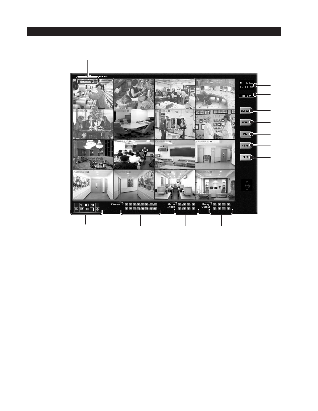
DISPLAY MODE
Display mode is the main screen of the DX7100 Series DVR. Use this screen to access Search, Setup, PTZ, and Copy modes.
1
2
3
4
5
6
7
8
12
1 Camera Name and Recording Status – The colored circle located to the right of the on-screen camera name indicates the
recording status of the camera. RED indicates that the video is being recorded continuously, BLUE means recording was
triggered by motion detection, YELLOW indicates sensor input recording, and CLEAR means the video is not being
recorded.
2 Date and Time Indicator – Displays current date and time.
3 Mode Identifier – Identifies the mode displayed on the screen. Available modes are DISPLAY, SETUP, PTZ, and COPY.
4 SEARCH Button – Click the SEARCH button to search and play back recorded video by date and time. Refer to the
section of this manual for more information.
5 SETUP Button – Click the SETUP button to program camera settings, customize a recording schedule, set up multiple
password levels, and show pan and tilt protocol. Refer to the
6 PTZ Control Button – Click the PTZ button to control pan, tilt, and zoom functions and to set and operate patterns, preset
tours, and presets. Refer to the
11
Figure 1. Display Mode
How to Operate PTZ
section of this manual for more information.
10
System Setup
section of this manual for more information.
9
Search
6 C642M (11/03)
Page 7
7 COPY Button (Backup) – Click the COPY button to format a CD-RW disk and to copy data to the internal CD-RW drive.
Refer to the section on
How to Backup Video Files
for more information.
8 EXIT Button – Click the EXIT button to exit the DX7100 program and shutdown the system.
CAUTION: Do not turn off the power switch on the DX7100 unless your system is locked up. If you must use
the power switch, hold it down until the system turns off.
9 Relay Output Buttons – Click a relay button (1-8) to turn on or off a device, such as a light or alarm, that is connected to
the relay output. A blue button indicates a relay is active.
10 Alarm Input Buttons – A blue button indicates an alarm has been activated. The button will stay blue until the alarm is
cleared.
11 Camera (Motion Detection Status) Buttons – A blue button indicates motion is detected. The button will remain blue until
motion is no longer detected.
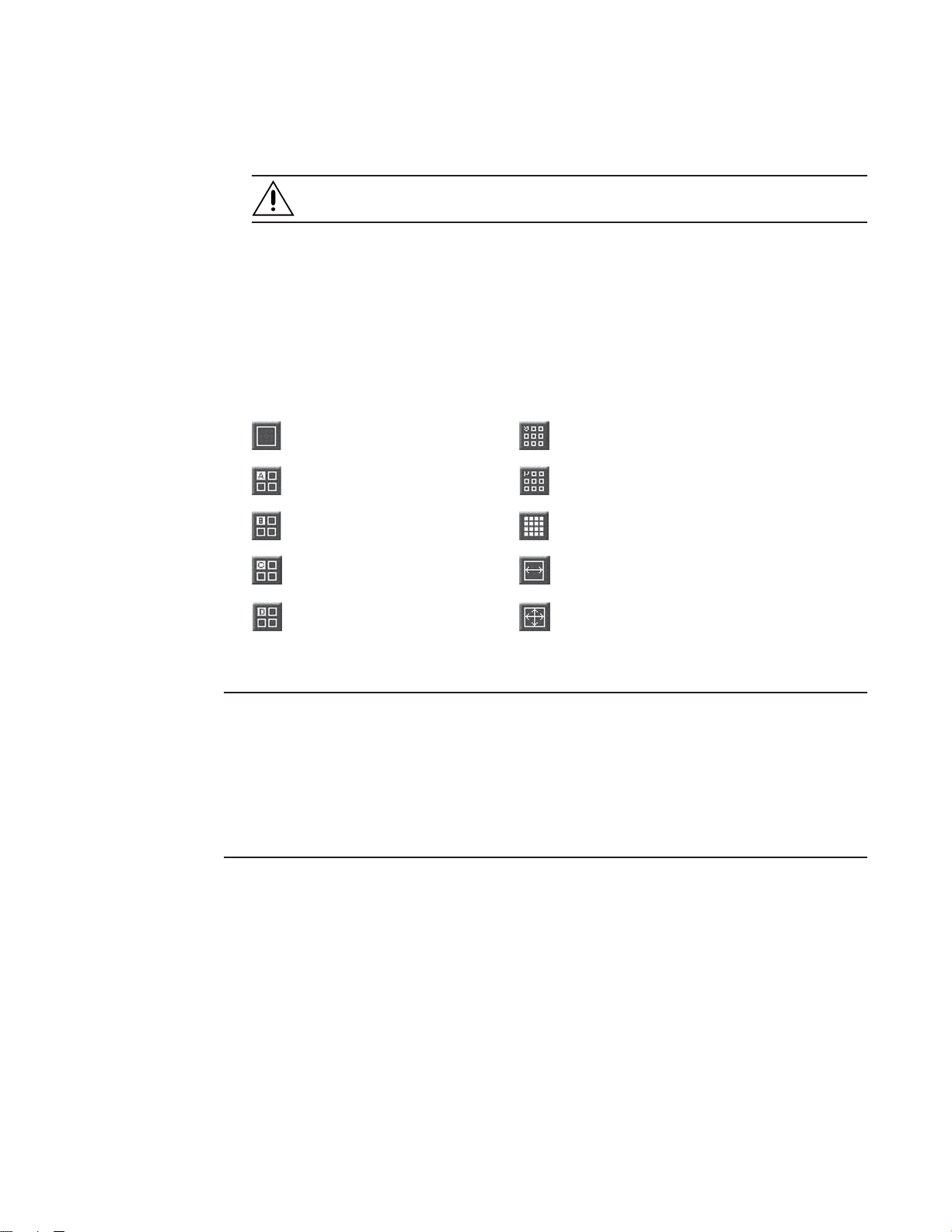
12 Screen Division Buttons
Displays a single camera. Displays cameras 1-9.
Displays cameras 1-4. Displays cameras 10-16.
Displays cameras 5-8. Displays all 16 cameras.
*
Displays cameras 9-12. Sequences using a single-, four-, or nine-camera display.
Displays cameras 13-16. Displays video on full screen; removes all buttons and status
*
NOTE: You can also use the left and right mouse buttons to change the screen division.
Single Camera Display Using the Mouse – Move the cursor to a camera view, and click the left mouse button. A green
rectangle appears around the selected view. Click the left mouse button again to display a single camera view of the selected
camera. To return to a 9-camera or 16-camera display, depending on the model, click the left mouse button again. You cannot
return to a 4-camera display from a single camera view.
Full-Screen Display Using the Mouse – Click the right mouse button anywhere on a camera scene to remove all buttons and
status indicators from the display. Click the right mouse button again to return to the previous screen display.
**
*
*
indicators from display. Click the right mouse button to
return to previous screen display.
*Settings are not available with DX7108 models.
**On DX7108 models, the last camera input is disabled.
C642M (11/03) 7
Page 8
SYSTEM SETUP
To set up the DX7100 digital video recorder, click the SETUP button located in the DISPLAY mode. The SETUP mode appears on
the screen. To exit the SETUP mode and return to the DISPLAY mode, click the EXIT button.
SYSTEM SETUP MENUS
Camera Setup
Insert camera name, enable camera, and set signal
type (NTSC/PAL).
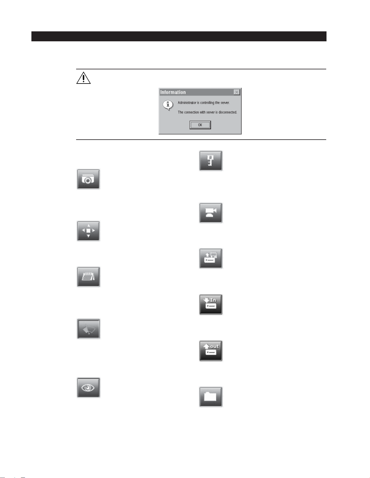
WARNING: The DX7100 server stops recording and all remote site users are disconnected during system setup. The
following message appears at all remote sites when they are disconnected:
Password Setup
Password levels include Administrator, Search User, PTZ/Backup
User, and Client User.
Color Setup
Adjust contrast, brightness, and picture level.
Schedule Setup
Specify recording start time, end time, day of week,
and recording mode (continuous, motion, or sensor).
Speed Setup
Set the frames per second (fps) for continuous
recording, motion detection, sensor detection, and
pre-alarm recording.
Motion Detection Setup
Select motion detection areas (maximum of 10 areas
per camera).
PTZ Setup
Shows the pan, tilt, and zoom protocol.
Update Program
Update the DX7100 software.
Import System Configuration
Import a system configuration file.
Export System Configuration
Export a system configuration file.
Quit To Explorer
Set a network address and hardware, or change system clock
settings using standard Windows® operations.
8 C642M (11/03)
Page 9
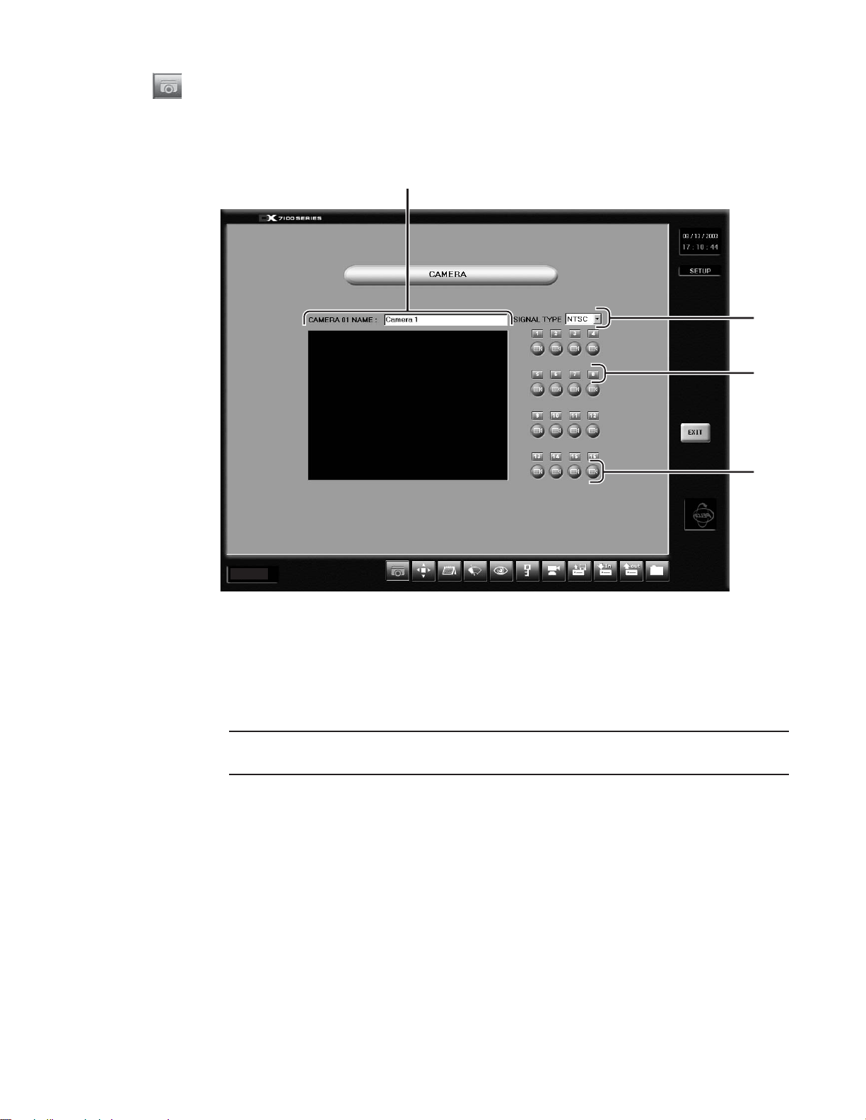
CAMERA SETUP
Use this screen to enable or disable camera inputs, name cameras, and set signal type (NTSC/PAL).
All cameras are enabled the first time the DX7100 DVR is started. Disable any camera input that is not being used. Disabled
cameras can increase the recording rate for other cameras.
1
2
3
4
Ver. 1.3
Figure 2. Camera Setup Menu
1 CAMERA NAME Box – To name a camera click the camera selection button for that camera. Up to 70 characters can be
entered in the box.
2 SIGNAL TYPE – Set the NTSC/PAL format for all cameras.
NOTE: The NTSC/PAL switch located on the back panel of the DVR must also be set for the correct signal. Refer to the
installation manual for more information.
3 Camera Selection Button – Select a camera. The scene of the selected camera appears in the viewing window.
4 Camera Enable Button – Enable each camera connected to the camera inputs. This allows all enabled cameras to be
viewed and recorded. If a camera is not connected to an input, disable the camera. Enabling or disabling cameras can
increase or decrease recording rate.
HOW TO SET UP A CAMERA
1. Click the CAMERA ENABLE button to enable a camera for setup. When the camera is enabled, the button is a light blue
color. If the button color is dark blue, the camera is disabled.
2. Click the CAMERA SELECTION button. The camera scene appears in the viewing window.
3. In the CAMERA NAME box, type in the camera’s name.
4. Set the NTSC/PAL format, which applies to all cameras.
C642M (11/03) 9
Page 10
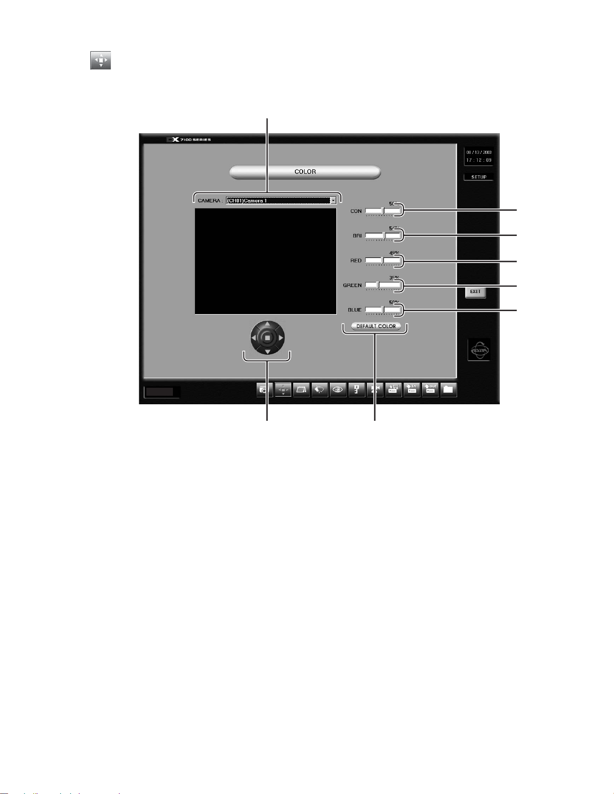
COLOR SETUP
If required, use this screen to adjust the contrast, brightness, and color level settings of a scene.
1
2
3
4
5
6
Ver. 1.3
8 7
Figure 3. Color Setup Menu
1 CAMERA Selection Box – Select a camera from the drop down menu.
2 CON (Contrast) Slider Bar – Drag the slider on the CON bar to change the contrast. Proper adjustment will allow
maximum gradations between the darkest and lightest parts of a scene.
3 BRI (Brightness) Slider Bar – Drag the slider to change the brightness. Adjust the brightness of the scene to compensate
for differences in lighting.
4 RED Slider Bar – Drag the slider to adjust the red color level.
5 GREEN Slider Bar – Drag the slider to adjust the green color level.
6 BLUE Slider Bar – Drag the slider to adjust the blue color level.
7 DEFAULT COLOR Button – Click the Default Color button to return all color settings to their default settings.
8 Image Alignment Buttons – Use the image alignment buttons (up, down, left, right, and center) to align the image within
the camera frame.
10 C642M (11/03)
Page 11
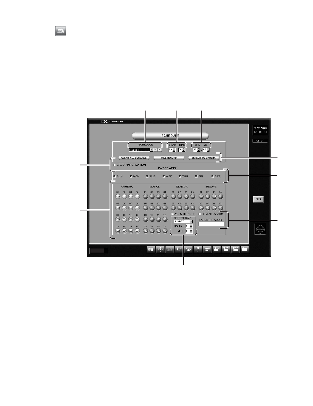
SCHEDULE SETUP
Twenty-four group schedules can be programmed to include the following:
Cameras to record
Day and time to record
Recording mode (continuous, motion, or sensor)
Evaluate the amount of movement at the surveillance site before programming a group schedule. Use one of the following
recording modes:
Continuous – Continuous recording is recommended for surveillance areas with a lot of movement.
Motion – Saves disk space; records only when motion is detected.
Sensor – Saves disk space; records only when an alarm is activated.
9
8
Ver. 1.3
1
2 3
4
5
6
7
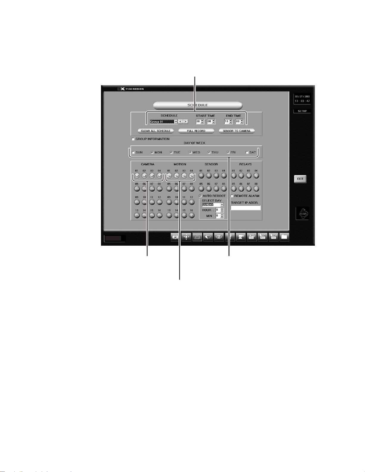
Figure 4. Schedule Setup Menu
C642M (11/03) 11
Page 12
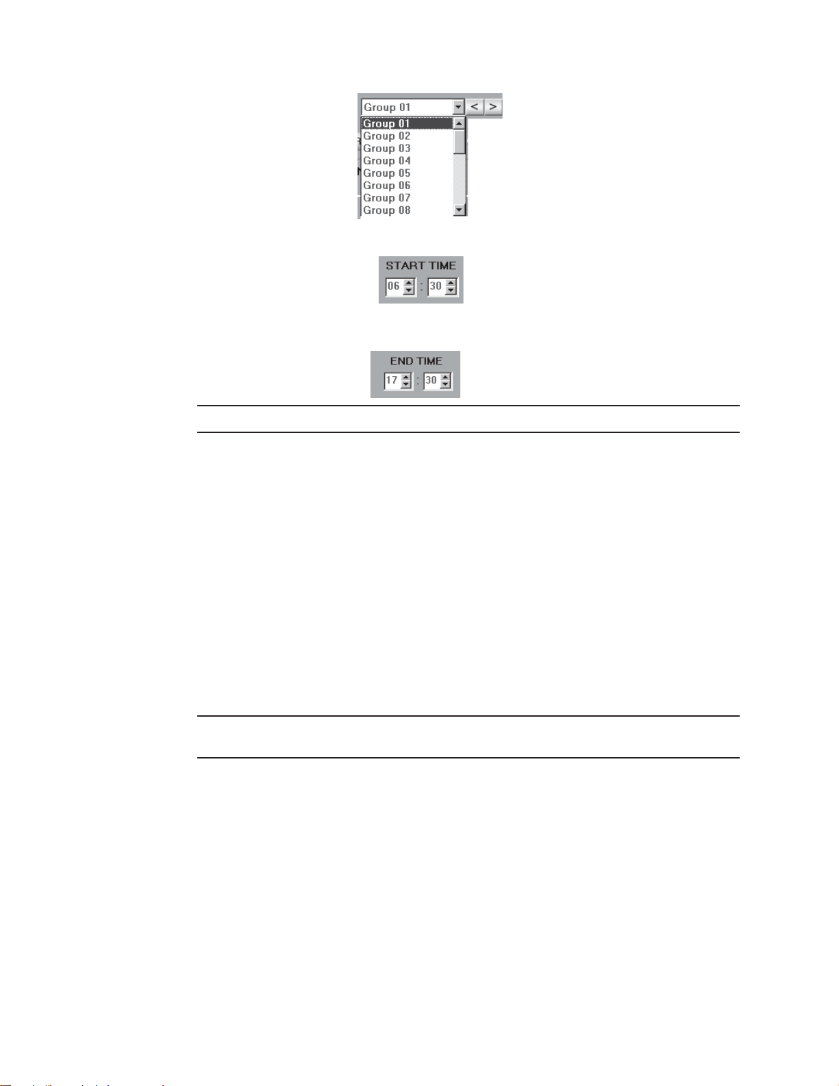
1 SCHEDULE (Group 01-24) – Use the drop down menu or arrow buttons to select a group (schedule).
2 START TIME – Program the time to start recording. If you want Group 1 to start recording at 6:30 in the morning, use the
arrow keys and set the START TIME to
3 END TIME – Program the time to stop recording. If you want Group 1 to stop recording at 5:30 in the evening, use the
arrow keys and set the END TIME to
NOTE: For continuous recording, set the start and stop times to 00:00.
4 CLEAR ALL SCHEDULE – CAUTION: Clears all group schedules.
FULL RECORD – This button automatically programs Group 1. It turns on all cameras enabled in the Camera menu. It
sets all days of the week for continuous recording. This button may be a useful programming tool if you want to record
many cameras continuously. After you press the button, you can change the settings; for example, you can turn
cameras off or deselect days of the week. CAUTION: Pressing this button clears all other group schedules.
SENSOR TO CAMERA – This button automatically assigns alarm input sensors to cameras and groups. Sensor 1 is
assigned to Camera 1, Group 1; Sensor 2 to Camera 2, Group 2; etc. Sensors are assigned only to the first eight
cameras and groups. This may be a useful programming tool for quickly assigning sensors to cameras and groups.
However, if you do not want to use this format, you can manually assign sensors as desired; for example, assign
Sensor 1 to Cameras 2, 9, and 16 in Group 9 (refer to item 8). CAUTION: Pressing this button clears all other
schedules.
5 DAY OF WEEK – Select the days of the week a group schedule will record.
6 REMOTE ALARM – Check the remote alarm box to notify a remote site when an alarm is activated.
TARGET IP ADDRESS – Enter the IP address of the remote site to alert when an alarm is activated.
NOTE: The Emergency Agent software must be installed on the remote site PC for the remote alarm function to work.
Refer to the
Emergency Agent Software
section of this manual for more information.
7 AUTO REBOOT – Set the day and time the system will reboot automatically. It is recommended that the DX7100 be
programmed to reboot weekly. The system will be momentarily unavailable during the reboot; recording and playback
functions will not be operational.
8 CAMERA, MOTION, SENSOR, AND RELAYS Buttons – Select the cameras, recording triggers, and relay outputs for the
group schedule.
If a camera button is enabled, that camera will record between the times specified in the start and end times.
If a motion button is enabled, that camera will record only if motion is detected between the times specified in the start
and end times. The corresponding camera button also must be enabled for motion detection to work.
If a sensor button is enabled, recording will occur if there is an alarm between the times specified in the start and end
times. Enable the camera or cameras that you want to record.
Both the motion and sensor buttons can be enabled for the same camera.
9 GROUP INFORMATION – Click the checkbox to list schedule conflicts between groups.
12 C642M (11/03)
Page 13
SCHEDULING EXAMPLE
Record four cameras with motion detection from Monday through Friday, 8:00 A.M. - 6:00 P.M.; Saturday, 8:00 A.M. - 2:00 P.M.; and
no recording on Sunday.
Step 1
– Select Group 01 and set the START TIME
to 8:00 and END TIME to 18:00.
Ver. 1.3
Step 3
– Select 01, 02, 03,
and 04 in CAMERA
section.
Step 4
– Select 01, 02, 03,
and 04 in MOTION
section.
Step 2
– Check MON, TUE,
WED, THU, and FRI
in the DAY OF WEEK
section.
C642M (11/03) 13
Page 14
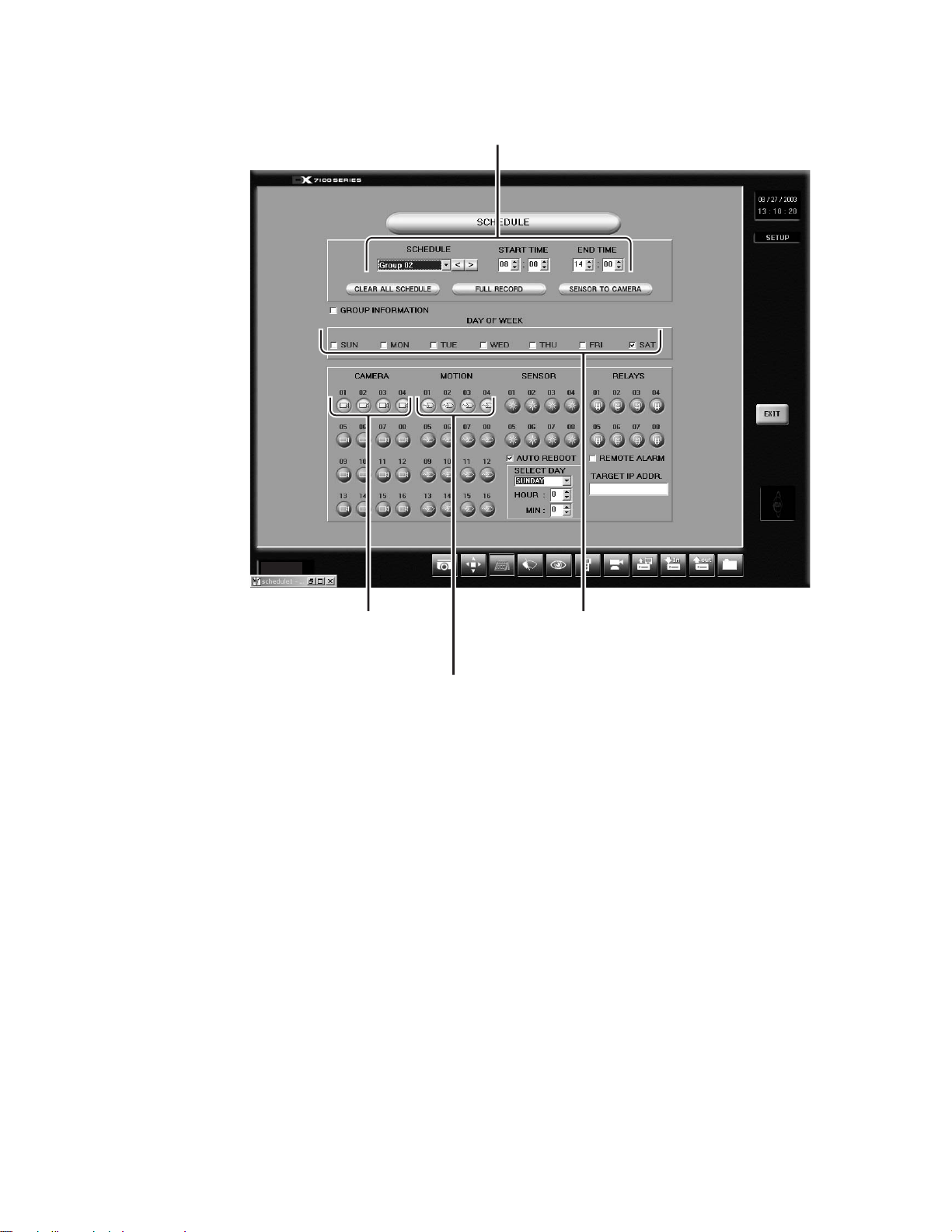
Step 5
– Select Group 02 and set the START TIME
to 8:00 and END TIME to 14:00.
Ver. 1.3
Step 7
– Select 01, 02, 03,
and 04 in CAMERA
section.
Step 8
– Select 01, 02, 03,
and 04 in MOTION
section.
Step 6
– Check SAT in the DAY
OF WEEK section.
14 C642M (11/03)
Page 15
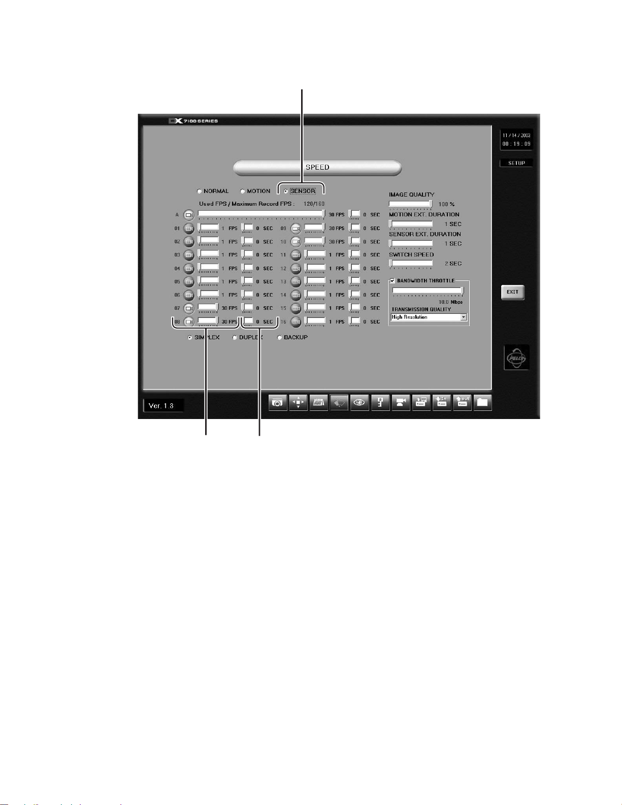
SPEED SETUP
Use the Speed Setup window to program the recording rate for each camera and to program the pre-alarm function for motion
and sensor recording modes.
NORMAL SPEED MENU
11
10
1
2 3
4
5
6
7
8
9
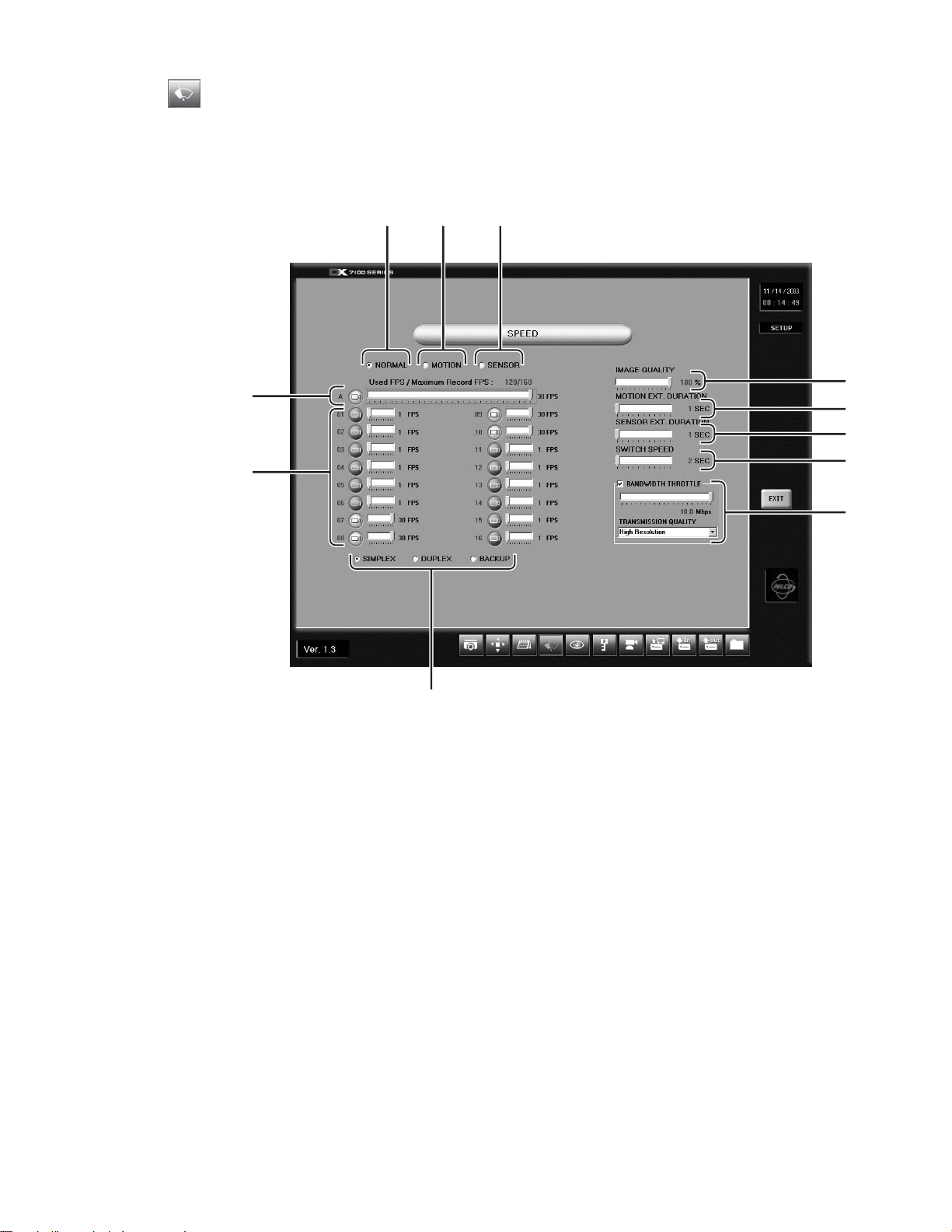
Figure 5. Speed Setup Menu
1 NORMAL Button – Opens the recording speed menu for continuous recording. You cannot program motion, sensor, or pre-
alarm speeds with this menu.
2 MOTION Button – Opens the motion detection and pre-alarm recording speed menu. Refer to the
section.
3 SENSOR Button – Opens the sensor detection and pre-alarm recording speed menu. Refer to the
section.
Motion Speed Menu
Sensor Speed Menu
C642M (11/03) 15
Page 16

NOTE: Items 4-9 affect the Normal, Motion, and Sensor menus. They should be set only once.
4 IMAGE QUALITY Slider Bar – Sets the quality of the recorded image. Image quality affects storage capacity and
transmission rate. More bandwidth and storage capacity is required for high quality images.
5 MOTION EXT. (Extended) DURATION Slider Bar – Sets recording time, from 1 to 180 seconds, after motion is detected.
6 SENSOR EXT. (Extended) DURATION Slider Bar – Sets recording time, from 1 to 180 seconds, after a sensor is triggered.
7 SWITCH SPEED – Sets the time, from 1 to 180 seconds, that cameras will sequence when the Sequence button is
activated in the DISPLAY mode.
8 BANDWIDTH THROTTLE – Sets the transmission rate for images sent to remote site users. Settings can be set from 0.5
to 10 Mbps in 0.5 Mbps increments. The default is 3 Mbps.
TRANSMISSION QUALITY includes high resolution of 320 x 240, medium resolution of 240 x 180 and low resolution of
160 x 120.
9 BACKUP – Select to customize recording rates when backing up data to the internal CD-RW drive.
DUPLEX – Select to customize recording rates during a search.
SIMPLEX – Select to customize recording rates during live viewing.
You must set the recording rates for all three modes. The DX7100 will select the recording rates automatically depending
on the mode in which you are using the DVR.
10 RECORDING SPEED Slider Bars – Control the recording rate of each camera by adjusting the control bar for each camera.
The total available fps for all cameras varies per system mode setup (simplex, duplex, or backup). For more information,
refer to the text following item 11.
11 Average (A) Recording Rate Slider Bar – Equally distributes the total available recording rate to all enabled cameras. All
enabled cameras are set to the same fps.
Example:
Total # of cameras Total FPS Average per camera
16 160 10
The total frames per second available to be distributed among all enabled cameras varies by the mode. In the simplex mode,
the maximum recording speed is 120 fps (DX7008 models) and 160 fps (DX7116 models). For all models, the maximum in
duplex mode is 60 fps and the maximum in backup mode is 40 fps.
The fps also is affected by the number of cameras enabled. In the example above, with all cameras enabled, the maximum fps
per camera is 10. But with only eight cameras enabled, the maximum fps can be increased to 20. (You do not have to leave the
cameras set for the maximum fps. You can use the individual slider bars or the averaging bar to change the fps.)
Another factor affecting fps is that cameras share bandwidth. Cameras 1 and 9, 2 and 10, 3 and 11, etc., share bandwidth. In
Figure 5, cameras 1 and 9, for example, share 30 fps. (The maximum fps per pair of cameras is 30.) Because Camera 1 is turned
off, Camera 9 gets all the bandwidth. But if Camera 1 is turned on (in the Camera menu), both cameras will be set for 15 fps.
16 C642M (11/03)
Page 17
MOTION SPEED MENU
1
2
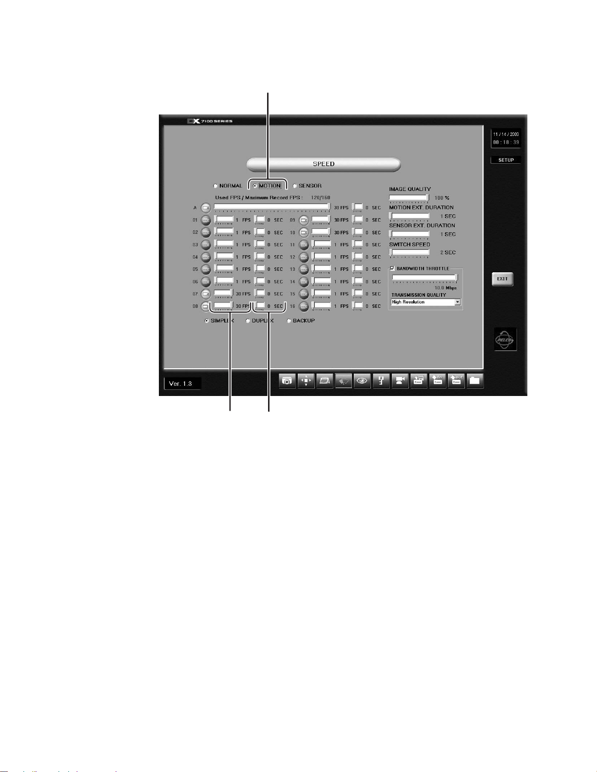
1 MOTION Button – Opens the motion speed menu. Use this menu to set motion detection and pre-alarm recording speeds.
2 Motion Recording Speed Slider Bar – Sets the recording rate for motion detection.
3 Pre-alarm Function Slider Bar – Programs the pre-alarm function for individual cameras. When motion is detected, images
are recorded for the programmed duration (five seconds maximum per camera) before the event happened.
To the right of the A (average) bar is a slider that sets the pre-alarm function for all cameras.
How can the DX7100 record video before motion occurs? Video is recorded for the amount of pre-alarm time, five seconds
for example, but as long as there is no motion, the five seconds of video is constantly overwritten with the latest five
seconds. When motion is detected, the DX7100 stops overwriting the video.
3
Figure 6. Motion Speed Menu
C642M (11/03) 17
Page 18
SENSOR SPEED MENU
1
2
1 SENSOR Button – Opens the sensor speed menu. Use this menu to set the sensor detection and pre-alarm recording
speeds.
2 Sensor Recording Speed Slider Bar – Sets the recording rate for sensor detection.
3 Sensor Pre-alarm Function Slider Bar – Program the pre-alarm function for individual cameras. When an alarm is
triggered, images are recorded for the programmed duration (five seconds maximum per camera) before the event
happened.
To the right of the A (average) bar is a slider that sets the pre-alarm function for all cameras.
How can the DX7100 record video before there is an alarm? Video is recorded for the amount of pre-alarm time, five
seconds for example, but as long as there is no alarm, the five seconds of video is constantly overwritten with the latest
five seconds. When there is an alarm, the DX7100 stops overwriting the video.
3
Figure 7. Sensor Speed Menu
18 C642M (11/03)
Page 19

MOTION DETECTION SETUP
Motion detection recording saves hard drive space and makes it easier to search and retrieve recorded data. Use the motion
detection menu to select the motion detection areas of a scene.
1
2
3
4
Ver. 1.3
5
Figure 8. Motion Detection Setup Menu
1 CAMERA Selection Box – Select the camera for motion detection setup.
2 BEEP Selection Box and Slider Bar – Select to sound an alarm at the DX7100 server when motion is detected. The alarm
can be set to beep for 1-10 seconds. The time setting applies to all cameras, but the beep can be set individually for each
camera. Note: The beep is only heard at the DX7100 server station and not at a remote site.
3 SENSITIVITY Slider Bar – Set the sensitivity of the detection areas for the selected camera.
NOTE: The sensitivity should be set to 40% for areas with normal movement. If the sensitivity level is set too high, the
slightest changes in light level and contrast will trigger motion detection. If the sensitivity is set too low, motion may not
be detected.
4 CLEAR ALL BLOCK Button – Deletes all motion detection area blocks for the selected camera.
5 Camera View – Indicates areas set for motion detection. Up to 10 detection areas, indicated by red boxes, can be set per
camera. To select an area, hold down the left mouse button and drag the mouse over the area. Each click of the mouse
button counts as a box. If you do not set any boxes, the entire view is selected for motion detection.
C642M (11/03) 19
Page 20

PASSWORD SETUP
DX7100 has four levels of password protection to prevent unauthorized changes or use of the system. The following are the
four password levels:
Server Administrator Set the password to access the Setup mode.
Search User Set the password to access the Search mode.
PTZ/Backup User Set the password the access the PTZ and Copy modes.
Connection User Set the password to access the system using the DX7100RX remote site software.
When a password is set, it will be requested before a user can access that mode. If there is no password, any user can access
that mode.
1
2
3
5
Figure 9. Password Setup Menu
1 SELECT LEVEL – Select a password level.
2 Password – View password. The actual password does not appear, only asterisks.
3 Number Buttons – Use number buttons to enter password. Enter up to 12 numbers.
4 ENTER Button – Saves password. If you are entering passwords for more than one level, click the button before moving
to another level.
4
5 CLEAR Button – Clears password. After clicking CLEAR, click ENTER.
20 C642M (11/03)
Page 21

PAN AND TILT SETUP
No settings are required to set the pan and tilt protocol for the DX7100. The only protocol available is D protocol.
Ver. 1.3
Figure 10. Pan and Tilt Protocol Menu
C642M (11/03) 21
Page 22

UPDATE PROGRAM
To update system software, do the following:
1. Click the Update Program button.
2. Select the drive and folder with the update software.
3. Select the update file labeled Setup and then click Open.
4. Follow the instructions that appear on the screen. When update is finished, the system will shutdown and then
automatically restart.
IMPORT SYSTEM CONFIGURATION
To import a DX7100 system configuration file, do the following:
1. Click the Import System Configuration button.
2. The dialog box “Do you want to change configuration?” appears on the monitor. Click the Yes button.
3. Select the drive where the configuration file is located, and then select the file. Click Open; the configuration file is
imported to the DX7100 hard drive.
EXPORT SYSTEM CONFIGURATION
To export a DX7100 system configuration file, do the following:
1. Click the Export System Configuration button.
2. The dialog box “Do you want to export configuration?” appears on the monitor. Click the Yes button.
3. Select where to save the configuration file by selecting the drive and file name. Click Save; the configuration file is
saved to the selected drive.
QUIT TO EXPLORER
The DX7100 uses a Windows-based operating system. To set a network address, add hardware, or change clock settings, click
the Quit To Explorer button. To return to the DX7100 program, close Explorer.
IMPORTANT: Consult your network administrator to avoid possible network conflicts and to obtain the information required
to set up a network address. To set up an IP address, go to Network and Dial-up Connections in the Control Panel.
22 C642M (11/03)
Page 23

HOW TO OPERATE PTZ
To control pan, tilt, and zoom functions and to set patterns, preset tours, and presets, click the PTZ button in the DISPLAY
mode. The PTZ mode appears on the screen. To exit the PTZ mode and return to the DISPLAY mode, click EXIT.
PATTERN BAR PRESET BAR
PRESET
BUTTONS
Figure 11. PTZ Menus
CAMERA
C642M (11/03) 23
Page 24

PTZ CONTROLS
To operate pan/tilt/zoom functions on controllable systems, do the following:
1. Select a camera.
2. Use the left and right arrow buttons to pan left and right.
3. Use the up and down arrow buttons to tilt up and down.
4. Use the FOCUS settings (+/-) to obtain the sharpest picture.
5. Use the ZOOM settings (+/-) to zoom near or far.
6. Use the SPEED settings (+/-) to increase or decrease the pan and tilt speeds. There are five speeds.
a. Move the mouse pointer to a camera view. Click the left mouse button. A green box appears around the
view. The camera number (1 through 16) appears in the center of the pan and tilt control (refer to Figure 12).
b. If you want a large-screen image, click the camera view again.
Figure 12. PTZ Controls
UP
RIGHTLEFT
CAMERA
DOWN
24 C642M (11/03)
Page 25

PATTERNS
The DX7100 can be programmed for one pattern for each camera. A pattern is a user-defined, viewable camera path with a
definite beginning and end. The pattern can consist of any standard pan and tilt or lens commands. Once defined the pattern is
easily activated with the press of an on-screen menu button. The pattern will run continuously until it is deactivated with
another press of the menu button.
HOW TO PROGRAM A PATTERN
1. Click the PTZ button in the DISPLAY mode. The PTZ mode appears.
2. Select a camera by moving the mouse pointer to the desired camera view and clicking the left mouse button. The
3. Click P-SET. ON appears on the P-SET button. Move the camera through a series of movements using the pan, tilt, zoom,
4. To stop programming the pattern, click the P-SET button.
5. To run the pattern, click the P-RUN button. ON appears on the P-RUN button. To stop the pattern, click the P-RUN button.
HOW TO CLEAR A PATTERN
Programming a new pattern will replace (clear) the pattern previously programmed.
PRESETS
NOTE: Spectra® or Esprit® programming menus can be accessed through preset 95 with a KBD200A or KBD300A keyboard in
the direct mode. Preset 95 does not work with the DX7100 controls.
A preset is a user-defined camera position using pan, tilt, zoom, and focus commands. The DX7100 Series DVR has programming capacity for 12 preset locations.
selected camera number is displayed in the center of the PTZ controls.
and focus commands.
HOW TO PROGRAM A PRESET
1. Click the PTZ button in the DISPLAY mode. The PTZ mode appears.
2. Click PRESET. The preset bar appears (refer to Figure 11).
3. Select a camera by moving the mouse pointer to the desired camera view and clicking the left mouse button. The
selected camera number is displayed in the center of the PTZ controls.
4. Move the camera to a desired position.
5. Click the SET button to turn on the preset programming.
6. Click a preset button 1-12. To set another preset for the same camera, move the camera and click another preset button.
7. Click the SET button to stop programming preset positions.
8. Repeat steps c-g to program a different camera.
HOW TO MOVE TO A PRESET
1. Click the PTZ button in the DISPLAY mode. The PTZ mode appears.
2. Click PRESET. The preset bar appears (refer to Figure 11).
3. Select a camera by moving the mouse pointer to the desired camera view and clicking the left mouse button. The
selected camera number is displayed in the center of the PTZ controls.
4. Click MOVE. ON appears on the button.
5. Click a preset button 1-12. The camera moves to the programmed preset position.
6. Click MOVE to turn off preset positioning.
HOW TO CLEAR A PRESET
1. Click the PTZ button in the DISPLAY mode. The PTZ mode appears.
2. Click PRESET. The preset bar appears (refer to Figure 11).
3. Select a camera by moving the mouse pointer to the desired camera view and clicking the left mouse button. The
selected camera number is displayed in the center of the PTZ controls.
4. Click CLEAR.
5. Click a preset button 1-12.
6. Click CLEAR to turn off clearing of presets.
C642M (11/03) 25
Page 26

PRESET TOURS
A preset tour is a programmed sequential execution of multiple preset positions.
HOW TO PROGRAM A PRESET TOUR
1. Click the PTZ button in the DISPLAY mode. The PTZ mode appears.
2. Click PRESET. The preset bar appears (refer to Figure 11).
3. Select a camera by moving the mouse pointer to the desired camera view and clicking the left mouse button.
4. Click the TOUR button to turn on tour programming.
5. Click the SET button to turn on preset programming.
6. Click preset buttons in any sequential order to program a tour.
7. To stop programming the preset tour, click the TOUR button.
HOW TO RUN A PRESET TOUR
1. Click the PTZ button in the DISPLAY mode. The PTZ mode appears.
2. Click PRESET. The preset bar appears (refer to Figure 11).
3. Click TOUR.
4. Set the time to switch between presets. The time selection buttons are located above the preset buttons.
5. Click MOVE. The preset tour starts. The number in the preset button turns orange to indicate which preset the tour is on.
6. To stop the tour click MOVE.
7. Click TOUR to exit touring.
HOW TO CLEAR A PRESET TOUR
1. Click the PTZ button in the DISPLAY mode. The PTZ mode appears.
2. Click PRESET. The preset bar appears (refer to Figure 11).
3. Click TOUR.
4. Click CLEAR. The preset tour is now cleared. A preset tour must be cleared before a new preset tour can be programmed.
5. Click TOUR to exit touring.
AUXILIARIES
The auxiliary buttons operate external equipment connected to the auxiliary outputs of Spectra domes or Esprit positioning
systems. Refer the documentation that accompanies your Spectra or Esprit equipment for operating instructions.
26 C642M (11/03)
Page 27

SEARCH
To search recorded data on the hard disk drive or internal CD-RW drive, click the SEARCH button located in the DISPLAY mode.
The SEARCH mode appears on the screen. To exit the SEARCH mode and return to the DISPLAY mode, click EXIT.
1
2
3
4
5
7 6
9101112131415 8
Figure 13. Search Mode
1 Year and Month to Search – Displays year and month to search.
2 Day Search – Days with recordings are highlighted with a yellow circle. The day selected is highlighted with a green
circle.
3 Search Time – Select the hour and minute to search.
4 Index Search Button – Displays search index.
Show/Hide Button – Shows or hides index.
Record Time Background Button – Changes the background color of the recording time. Available settings are blue
and clear.
1. Stop playback.
2. Click the button.
3. Click the play button. The background color changes.
C642M (11/03) 27
Page 28

5 Playback Buttons – Use to search saved data. In fast playback, the DX7100 plays back one camera at 16X normal speed,
four cameras at 8X normal speed, eight cameras at 2X normal speed, and sixteen cameras at normal speed.
PLAYBACK
PREVIOUS IMAGE
GO TO THE FIRST IMAGE
RECORDED ON HDD
FAST PLAYBACK
NEXT IMAGE
STOP
GO TO LAST IMAGE
RECORDED ON HDD
00953
Figure 14. Playback Buttons
6 Close CD Tray Button – Closes CD-RW tray. Playback must be stopped before button can be used.
7 Open CD Tray Button – Opens CD-RW tray. Playback must be stopped before button can be used.
8 Primary/Secondary Device Button – Toggles between searching for data on hard drive or CD-RW drive. Playback must be
stopped before button can be used.
9 AVI Button – Creates and saves an AVI file to a backup storage device. Refer to the
AVI Backup
section. To view saved
AVI files use a PC Media Player that supports the AVI file format. Playback must be stopped before button can be used.
(Use with single display playback only.)
10 Print Button – Prints image. Playback must be stopped before button can be used. (Use with single display playback only.)
11 FDD Button – Saves recorded image to 3.5-inch diskette in JPEG or bitmap format. Playback must be stopped before button
can be used. (Use with single display playback only.)
12 Zoom/Contrast/Brightness Buttons – Adjusts levels for recorded image. (Use with single display playback only.)
13 Camera Button – Displays camera buttons.
Info Button – Displays the amount of data on the selected drive.
Slider Button – Displays slider bars (refer to Figure 16).
14 Camera Buttons – Select cameras to view. The default setting of the DX7100 turns all cameras on. If you do not want to
view all cameras, click a button to turn a camera off.
15 Screen Division Buttons – Select single-camera or multiple-camera views.
To select a single camera, click the button on the far right (X). This turns off all cameras. Then select the desired camera.
A single camera must be selected before you can use the AVI, print, or FDD buttons.
NOTE: When in Search mode, select Shift+V to view software version and build date.
Refer to the following page for instructions on how to use the Search mode.
28 C642M (11/03)
Page 29

DATE AND TIME SEARCH
b
c
d
e
a
1 Click the Camera button if the camera buttons are not shown in the lower-left corner of the screen.
2 Select the cameras you want to search. The default setting of the DX7100 turns all cameras on. If you do not want to
search all cameras, click the individual camera buttons to turn off the ones you do not want to search.
3 Use the arrow buttons to select the year and month to search.
4 Select the day to search. Days with recordings are highlighted with a yellow circle. The selected day is highlighted with a
green circle.
5 Use the arrow buttons to select the hour and minute to search.
6 Use the playback buttons to review the recordings.
3
4
12
Figure 15. Date/Time Search
5
6
C642M (11/03) 29
Page 30

SLIDER SEARCH
b
c
d
e
a
a
The slider search is similar to the time and date search but provides additional information to help you narrow your search. The
slider bar shows the types of video (normal, motion, and sensor) that have been recorded.
1 To do a slider search, follow steps 1-4 in the time and date search, and then click the Slider button.
2 Select a camera to see what kinds of video have been recorded. Use the arrow buttons to the right of the bottom bar. The
camera number appears to the left of the bottom bar.
3 Select the hour to search in the top bar. Recordings are highlighted in green. Place the mouse pointer on the green bar
under the exact time and click the left mouse button.
Select the minute to search in the bottom bar. Normal recording is highlighted with red, motion recording is highlighted
with blue, and alarm recording is highlighted with yellow. Place the mouse pointer on the bar under the exact time and
click the left mouse button.
NOTE: The time selected applies to all cameras, not just the one you have picked on the slider bars.
Use the playback buttons to review the recordings (refer to Figure 15).
3
Figure 16. Slider Search
122
30 C642M (11/03)
Page 31

INDEX SEARCH
1 Click the INDEX SEARCH button. A blank Index List (3) appears.
2 Select the year, month, and day.
3 Select the event type (motion or sensor) to search.
Enter the START TIME and END TIME of search.
In the fall when there is a change from daylight time to regular time, there will be two hours of recording between 1 A.M.
and 2 A.M., one hour before the time change and one hour after the time change. The Daylight Time checkbox can be used
only on day of the time change. To view the hour before the time change, make sure the Daylight Time checkbox is not
selected. To view the hour after the time change, click the Daylight Time checkbox to select it.
4 Click the Camera button if the camera buttons are not shown in the lower-left corner of the screen.
5 Select a camera to view. Only one camera can be searched at a time.
Depending on the amount of data it may take several minutes before an Index List is displayed. Double-click one of the
data files to display the recording.
6 Use the playback buttons to review a recording.
3
2
1
6
54
Figure 17. Index Search
C642M (11/03) 31
Page 32

HOW TO BACKUP VIDEO FILES
Video files can be backed up on an internal CD-RW drive.
BACKUP WINDOW
1
2
3
4
12
11
10
Figure 18. Backup (COPY) Window
1 SELECT DRIVE Box – Lists drives with files available for backup.
2 STORED ITEM(S) Box – Lists all files stored in the selected drive.
3 ADD Button – Adds stored files to ITEM(S) TO BACKUP box.
4 ITEM(S) TO BACKUP Box – Lists files selected for backup.
5 CLEAR ALL Button – Clears all files in the ITEM(S) TO BACKUP box.
6 SPACE NEEDED Indicator – Shows the amount of space required to backup selected files.
7 HIDE Button – Closes the backup window.
789
5
6
01180
8 FORMAT Button – Use to format a CD-RW disk.
9 STOP Button – If the backup process to the CD-RW disk has been initiated, the STOP button ends the copying session.
10 BACKUP Button – Starts to backup (copy) the files in the ITEM(S) TO BACKUP box to the CD-RW disk.
11 DESTINATION DRIVE – Identifies the CD-RW drive and its available storage capacity.
12 REMOVE Button – Deletes selected files from the ITEM(S) TO BACKUP box.
32 C642M (11/03)
Page 33

HOW TO BACKUP (COPY) TO THE CD-RW DRIVE
1. From the DISPLAY mode of the DX7100, click the COPY button. The backup window appears.
2. Select a drive from the SELECT DRIVE box. After several minutes a list of files will appear in the STORED ITEM(S) box.
3. Use the left mouse button to select files to backup. Click the ADD button. The selected files appear in the ITEM(S) TO
BACKUP box.
4. Insert a CD-RW disk in the CD-RW drive. Only use formatted CD-RW disks. Do not use CD-R disks.
To format an unformatted CD-RW disk or to erase information on a CD-RW disk, insert the disk, press the FORMAT
button, and follow the on-screen instructions. The formatting operation takes approximately five minutes.
5. To finish the backup process click the BACKUP button. A Backup indicator in the bottom right-hand corner of the screen
shows that the files are being written to the CD-RW drive (refer to Figure 19).
6. To exit the backup window, click the HIDE button.
NOTE: The CD-RW tray opens. Make sure the front door of the DVR is open.
To view the video on the CD, use the Backup Viewer.
STORAGE INDICATOR IS NOW LABELED BACKUP
7
Figure 19. Storage Indicator Is Now Labeled BACKUP
C642M (11/03) 33
Page 34

REMOTE SITE SOFTWARE
DESCRIPTION
Free remote site software is included with the DX7100 to provide remote site viewing of live and recorded video. The software
is compatible with Windows 98, Windows 2000, Windows XP, and Windows NT
INSTALLATION
To install the remote users software, do the following:
1. Start Windows 98, Windows 2000, Windows XP, or Windows NT 4.0 Service Pack 6.
2. Close all programs, including any antivirus programs.
3. Insert the Remote Users Software CD into the CD-ROM drive.
4. The Windows Setup wizard starts. Follow the instructions that appear.
5. The DX7100 Series software installation program appears.
®
a. If required, install the Direct X
b. Install the Remote Client program (DX7100 RX).
c. Restart the computer.
application programming interface.
®
4.0 Service Pack 6.
Figure 20. DX7100 Series Remote User Software Installation Menu
IMPORTANT:
Minimum PC Requirements for Remote Site Software:
Pentium® III processor, 700 MHz; 128 MB of memory; 1024 x 768 minimum display setup; 32-bit color display; 32 MB video
card. (Do not change screen resolution when program is running.)
Recommended VGA Cards:
ATI RAGE™ 128, ATI RAGE 128Pro, NVIDIA RIVA TNT2™ Model 64, NVIDIA RIVA TNT2 Model 64 Pro, NVIDIA GE Force™2
MX400, Savage4, or Savage4 Pro. All cards should have a minimum of 16 MB of video RAM.
34 C642M (11/03)
Page 35

2
REGISTERED SITE SETUP
2 3 4 5
1
6
7
8
9
10
11
13
1
15
Figure 21. Setup Screen
1 Date and Time Indicator – Displays current date and time on the local machine.
2 CLIENT ADMIN PASSWORD Box — Enter the Administrator password. The first time the remote site software is used,
the system administrator should enter a password to prevent unauthorized access to this screen. Entering a password
also controls access to the remote site; that is, the user will be asked for the password when he presses the CONNECT
button (refer to
NOTE: You must have Windows Administrator privileges to access setup page.
3 SWITCH SPEED Slider Bar – Set the sequencing time between cameras for the remote site.
4 USE BEEP Selection Box and Slider Bar – Click the checkbox to be alerted when motion is detected. Use the slider bar
to set the duration of the beep.
5 OVERLAY MODE Box – Click the arrow to open a drop-down menu. Select NON-OVERLAY mode if your computer is
using Windows NT or if your PC video card does not support multiple layers.
6 SITE NAME Box – Enter the name of the site.
Remote Software Operation).
14
C642M (11/03) 35
Page 36

7 ADDRESS Box – Enter the IP address or phone number of the site.
8 CONNECTION PASSWORD Box – Enter the Connection User password of the server, if the server has one.
9 SEARCH PASSWORD Box–– Enter the Search User password of the server, if the server has one.
10 CHANNEL NAME Box – Click the left and right arrow buttons to select a camera (channel). The name defaults to the
server camera name. To rename the camera for the remote site, type the new name in the box.
11 TRANSMISSION SIZE Box – Click the arrow to open a drop-down menu of image selections: high resolution of 320 x 240,
medium resolution of 240 x 180, or low resolution of 160 x 120.
12 EXIT Button – Exits the registered site setup screen.
13 TRANSMISSION SPEED Slider Bar – Set the speed that the remote site can receive data, from 0.5 to 10 Mbps in 0.5
Mbps increments. The setting should be the same or lower than the transmission speed from the server.
14 SELECT CHANNEL Selection Boxes and Buttons – Selects cameras to view.
15 REGISTERED SITE LIST Box and Buttons – Creates a new registered site or deletes a registered site from the list.
HOW TO SET UP A REGISTERED SITE
1. Start Windows.
2. Click the icon for the DX7100 Remote Client Software. The remote site screen appears.
3. Click the SETUP button.
4. At the bottom of the REGISTERED SITE LIST, click NEW.
5. Input the information or select the options in the fields on the screen.
6. Check the desired cameras to be displayed.
7. Click the EXIT button to finish setup.
NOTE: Windows NT does not support overlay mode.
HOW TO CONNECT TO A REMOTE SITE
1. Click the icon for the DX7100 Remote Client Software. The remote site screen appears.
2. Select the site in the SITE NAME box.
3. Click the site name.
4. Click the CONNECT button.
5. Enter Client Admin password if requested.
36 C642M (11/03)
Page 37

REMOTE SOFTWARE OPERATION
1
2
3
4
78910 6 5
Figure 22. On-Line Mode
1 Date and Time Indicator – Displays current date and time.
2 SEARCH Button – Searches and plays back recordings by date and time.
3 PTZ Control Button – Controls pan, tilt, and zoom functions.
4 CONNECT/DISCONNECT Button – Connects to the domain site or disconnects from the domain site. If an Administrator
password was established for the remote site (refer to
can connect to the site.
5 REMOTE UPDATE Button – Click to update the software or to copy the system configuration from one server to another.
6 AVI Button – Creates and saves an AVI file to any hard drive on your PC or a backup storage device connected to your PC.
Refer to the
AVI Backup
section. To view saved AVI files use a PC Media Player that supports the AVI file format.
Registered Site Setup),
you must enter the password before you
C642M (11/03) 37
Page 38

7 RELAY OUTPUT Buttons – Turn relays connected to DX7100 DVR on or off.
8 DOMAIN/IP ADDRESS Text Box – Displays address of domain site.
9 SITE NAME Text Box – Displays name of domain site.
10 Screen Division Buttons
Displays a single camera.
Displays cameras 1-4.
Displays cameras 5-8.
*
*
NOTE: You can also use the left and right mouse buttons to change the screen division.
Single Camera Display Using the Mouse – Move the cursor to a camera view, and click the left mouse button. A green
rectangle appears around the selected view. Click the left mouse button again to display a single camera view of the selected
camera. To return to the previous screen display, click the left mouse button again.
Full-Screen Display Using the Mouse – Click the right mouse button anywhere on a camera scene to remove the menu bars
from the display. Click the right mouse button again to return to the previous screen display.
Settings are not available with DX7108 models.
*
**On DX7108 models, the last camera input is disabled.
Displays cameras 9-12. Sequences using a single-, four-, or
Not available in non-overlay mode. nine-camera display.
Displays cameras 13-16. Displays video on full screen; removes menu bars from
Not available in non-overlay mode. display. Click the right mouse button to return to previous
**
*
*
Displays cameras 1-9.
Not available in non-overlay mode.
Displays cameras 10-16.
Not available in non-overlay mode.
Displays all 16 cameras.
Not available in non-overlay mode.
screen display.
38 C642M (11/03)
Page 39

PTZ CONTROL MODE
To operate pan, tilt, and zoom functions on controllable systems, do the following:
1. Click the PTZ button in the ON LINE mode. The PTZ mode appears.
2. Select a camera.
a. Move the mouse pointer to a camera view. Click the left mouse button. A green box appears around the view. The
camera number (1 through 16) appears in the center of the pan and tilt control (refer to Figure 23).
b. If you want a large-screen image, click the camera view again.
3. Use the left and right arrow buttons to pan left and right.
4. Use the up and down arrow buttons to tilt up and down.
5. Use the FOCUS settings (+/-) to obtain the sharpest picture.
6. Use the ZOOM settings (+/-) to zoom near or far.
7. Use the SPEED settings (+/-) to increase or decrease the pan and tilt speeds. There are five speeds.
NOTE: When performing pan, tilt, and zoom functions over a network, there may be a delay in response at the DX7100.
Figure 23. PTZ Controls
UP
RIGHTLEFT
CAMERA
DOWN
C642M (11/03) 39
Page 40

PATTERNS
The DX7100 can be programmed for one pattern. A pattern is a user-defined, viewable camera path with a definite beginning
and end. The pattern can consist of any standard pan and tilt or lens commands. Once defined the pattern is easily activated
with the press of an on-screen menu button. The pattern will run continuously until it is deactivated with another press of the
menu button.
How to Program a Pattern
1. Click the PTZ button in the DISPLAY mode. The PTZ
mode appears.
2. Select a camera by moving the mouse pointer to the
desired camera view and clicking the left mouse
button. The selected camera number is displayed in the
center of the PTZ controls.
3. Click P-SET. ON appears on the P-SET button. Move the
camera through a series of movements using the pan,
tilt, zoom, and focus commands.
4. To stop programming the pattern, click the P-SET
button.
5. To run the pattern, click the P-RUN button. ON appears
on the P-RUN button. To stop the pattern, click the
P-RUN button.
How To Clear a Pattern
Programming a new pattern will replace (clear) the pattern
previously programmed.
AUXILIARIES
The auxiliary buttons operate external equipment connected
to the auxiliary outputs of Spectra domes or Esprit
positioning systems. Refer the documentation that
accompanies your Spectra or Esprit equipment for operating
instructions.
Figure 24. Pattern Bar
40 C642M (11/03)
Page 41

PRESETS
A preset is a user-defined camera position using pan, tilt, zoom, and focus commands. The DX7100 Series DVR has programming
capacity for 12 preset locations.
NOTE: The selected camera is indicated by the number displayed in the center of the PTZ controls. Refer to Figure 23.
How to Move to a Preset
1. Click the PTZ button in the ON LINE mode. The PTZ mode appears.
2. Click PRESET. The preset bar appears (refer to Figure 25).
3. Select a camera by moving the mouse pointer to the desired camera view and clicking the left mouse button. The
selected camera number is displayed in the center of the PTZ controls.
4. Click MOVE. ON appears on the button.
5. Click a preset button 1-12. The camera moves to the programmed preset position.
6. Click MOVE to turn off preset positioning.
NOTE: Presets cannot be programmed with the remote site software.
C642M (11/03) 41
Page 42

PRESET TOURS
A preset tour is a programmed sequential execution of preset positions from the DX7100 DVR.
How to Run A Preset Tour
1. Click the PTZ button in the ON LINE mode. The PTZ mode appears.
2. Click PRESET. The preset bar appears (refer to Figure 25).
3. Click TOUR. The preset tour starts.
4. To stop the tour click the TOUR button.
PATTERN BAR PRESET BAR
PRESET
BUTTONS
CAMERA
Figure 25. Pattern and Preset Bars
42 C642M (11/03)
Page 43

SEARCH MODE
Click the SEARCH button in the ON LINE mode. The SEARCH mode appears.
1
2
3
4
5
6
7
8
9
11
Figure 26. Search Mode
1 Date and Time Indicator – Displays current date and time.
2 Search Date Selection Boxes – Select month and year to search video.
3 Search Time Selection Boxes – Select the time (hour and minute) to search video.
4 Selected Camera Box – Shows the camera selected for a single camera view or when using the FDD, print, and AVI buttons.
5 Select Drive Selection Box – This function is not active unless you are connected to a DX7000 Series DVR.
6 Data Information Box
1012
C642M (11/03) 43
Page 44

7 FDD Button – Saves recorded image to 3.5-inch diskette. Playback must be stopped before button can be used.
Print Button – Prints image. Playback must be stopped before button can be used.
AVI Button – Creates and saves an AVI file to a backup storage device. Playback must be stopped before button can
be used. Refer to the
Record Time Background Button – Use this button if the time stamp is not visible. Available settings are blue and
clear.
1. Stop playback.
2. Click the button.
3. Click the play button. The background color changes.
AVI Backup
section. To view saved AVI files, use a PC Media Player that supports the AVI format.
8 EXIT Button – Exits search screen.
9 Playback Control Buttons
10 Screen Division Buttons
11 Calendar Button – Displays calendar for choosing playback date.
Slider Button – Displays slider bars (refer to Figure 27).
12 Calendar – Dates with a yellow circle indicate that video was recorded on that day. The selected day is highlighted with a
green circle.
NOTE: When in Search mode, select Control+V to view software version and build date.
44 C642M (11/03)
Page 45

DATE AND TIME SEARCH
1
Click the Calendar button if the calendar is not shown in the lower-left corner of the screen.
2 Enter the year and month in the Search Date selection boxes. Click the up or down arrow buttons to make a selection.
3 Enter the hour and minute in the Search Time selection boxes. Click the arrow buttons up or down to make a selection.
4 Select drive. This function is not active unless you are connected to a DX7000 Series DVR.
5 Select the screen view.
6 Select the date from the calendar. Dates with recordings are highlighted with a yellow circle. Click a highlighted date.
7 Use the playback buttons to review the recordings.
2
3
1
Figure 27. Search Mode
4
7
56
C642M (11/03) 45
Page 46

a
SLIDER SEARCH
The slider search is similar to the time and date search but provides additional information to help you narrow your search. The
slider bar shows the types of video (normal, motion, and sensor) that have been recorded.
1 To do a slider search, follow steps 1, 2, 4, and 5 in the time and date search, and then click the Slider button.
2 Select a camera to see what kinds of video have been recorded. Use the arrow buttons to the right of the bottom bar.
The camera number appears to the left of the bottom bar.
3 Select the hour to search in the top bar. Recordings are highlighted in green. Place the mouse pointer on the green bar
under the exact time and click the left mouse button.
Select the minute to search in the bottom bar. Normal recording is highlighted with red, motion recording is highlighted
with blue, and alarm recording is highlighted with yellow. Place the mouse pointer on the bar under the exact time and
click the left mouse button.
NOTE: The time selected applies to all cameras, not just the one you have picked on the slider bars.
Use the playback buttons to review the recordings (refer to Figure 27).
3
Figure 28. Slider Search
122
46 C642M (11/03)
Page 47
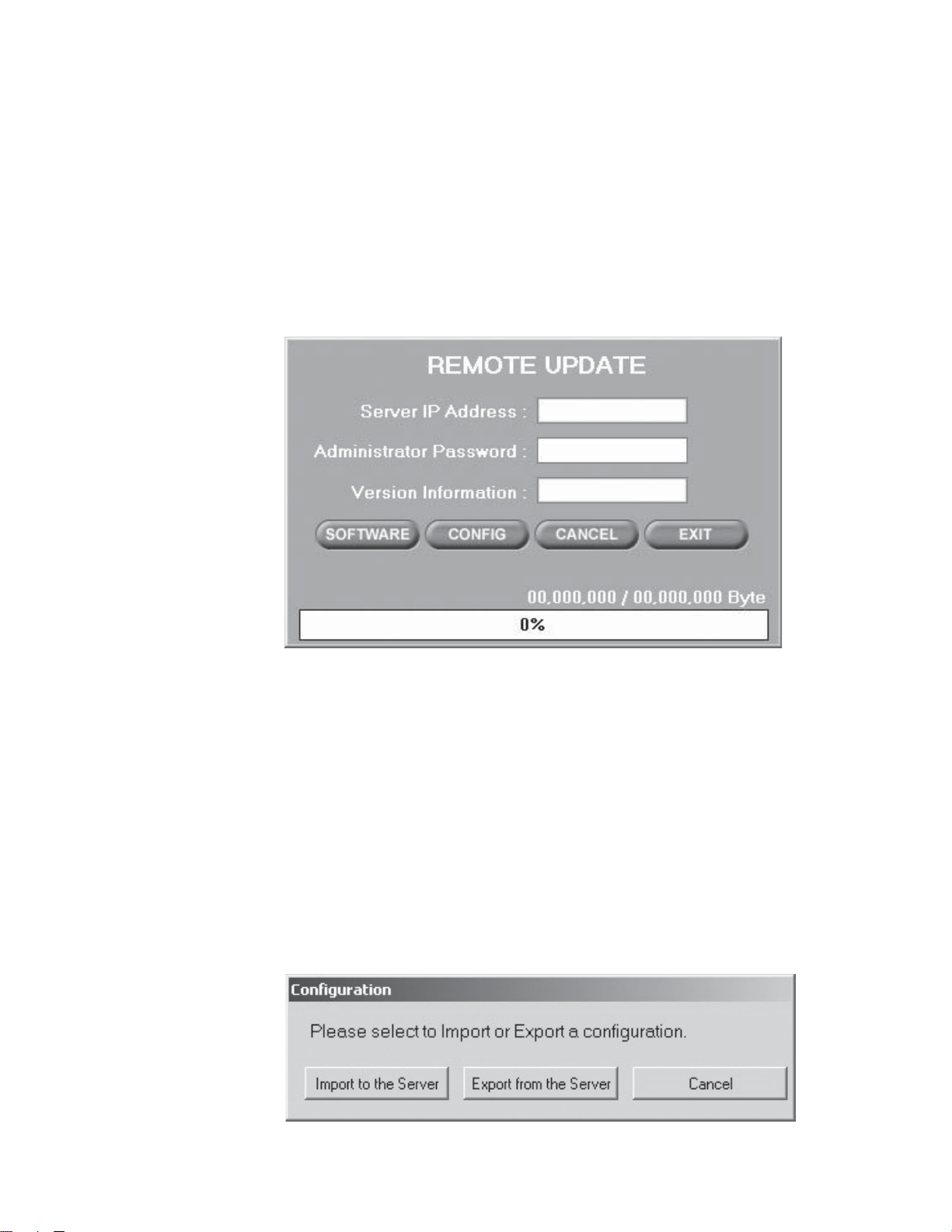
REMOTE UPDATE
SOFTWARE UPDATE
1. Click the Remote Update button.
2. Enter the Administrator Password if there is one for the remote site.
3. Click SOFTWARE. The following warning message appears:
“All the connections with the server will be lost.”
4. Click Yes. Choose the update file.
5. Click Open. The update begins.
6. When the update is finished, click Yes when prompted to restart the DX7100 server.
Figure 29. Remote Update Dialog Box
CONFIGURATION UPDATE
Use this program to export the system configuration file from the server and then import it to another server.
1. Click the Remote Update button.
2. Enter the Administrator Password if there is one for the remote site.
3. Click CONFIG.
4. Click either Import to the Server or Export from the Server. The following warning message appears:
“If you upload (download) this configuration file, then all connections with the server will be closed.
5. Click Yes.
6. Click Save.
7. If you are importing the configuration file, click Yes when prompted to restart the server when the import is finished.
Figure 30. Selection Box to Import or Export Configuration
C642M (11/03) 47
Page 48

EMERGENCY AGENT SOFTWARE
Figure 31. Emergency Agent Window
Emergency Agent software alerts the remote site client of any triggered alarm at the surveillance site. When an alarm is
triggered, a pop-up window appears on the monitor of the remote site client. The window displays a detailed list (date and
time) of all images recorded during the alarmed event.
To install the Emergency Agent software, follow these steps.
1. Start Windows.
2. Close all programs, including any antivirus programs.
3. Insert the Remote Users Software CD into the CD-ROM drive.
4. The Windows Setup wizard starts. Follow the instructions that appear.
5. The DX7100 Series software installation program appears. Click the Emergency Agent software button and follow the
instructions.
6. Restart the computer.
NOTE: For the Emergency Agent Software to operate, the DX7100 system at the surveillance site must be setup for remote
alarm operation. To set up the DX7100 DVR for remote alarm operation, refer to the
To view the transmitted images, click the stop button (circle with a slash through it) and then use the playback buttons located
at the bottom of the Emergency Agent software window.
Schedule Setup
section.
48 C642M (11/03)
Page 49

BACKUP VIEWER SOFTWARE
Use the Backup Viewer software to search images stored on a CD-ROM or hard drive on your computer.
HOW TO INSTALL THE BACKUP VIEWER
1. Start Windows.
2. Close all programs, including any antivirus programs.
3. Insert the Remote Users Software CD into the CD-ROM drive.
4. The Windows Setup wizard starts. Follow the instructions that appear.
5. The DX7100 Series software installation program appears. Click the Backup Viewer software button and follow the
instructions.
6. Restart the computer.
HOW TO OPEN THE BACKUP VIEWER
1. Click the Backup Viewer icon on your computer. The following dialog box appears.
Figure 32. Backup Version Selection
2. Select the option for the type of server you have. Click OK. The following dialog box appears.
C642M (11/03) 49
Page 50

Figure 33. Backup Mode Selection
3. Select the number of cameras you want to view.
4. Select the media type, either CD-ROM or HDD. DAT and DVD are not supported. If you choose HDD, then select the hard
drive.
5. Deselect the Overlay Mode if your computer is using Windows NT or if your video card does not support multiple layers.
6. Click OK. The Backup Viewer screen appears. Refer to the next section for instructions on how to use the Backup Viewer.
50 C642M (11/03)
Page 51

OPERATION
1
2
3
4
5
6
7
1516
14
10 91213
8
11
Figure 34. Backup Viewer
1 Date and Time Indicator – Displays current date and time.
2 Year and Month Selection Boxes – Displays the year and month to search. Use the up and down arrows to select a date.
3 Day Search Selection Box – Days with recordings are highlighted with a yellow circle. The day selected is highlighted by
a green circle.
4 Search Time Selection Boxes – Select the hour and minute to search.
5 Index Search Button – Displays search index.
Show/Hide Button – Shows or hides index.
Record Time Background Button – Use this button if the time stamp is not visible. The background color of the
recording time will change. Available background settings are blue and clear.
1. Stop playback.
2. Click the button.
3. Click the play button. The background color changes.
C642M (11/03) 51
Page 52

6 EXIT Button – Exits Backup Viewer.
7 Playback Buttons
8 Close CD Tray Button – Closes CD tray. Playback must be stopped before button can be used. This button does not appear
if you are viewing data from a hard drive.
9 Open CD Tray Button – Opens CD tray. Playback must be stopped before button can be used. This button does not appear
if you are viewing data from a hard drive.
10 AVI Button – Creates and saves an AVI file to a selected drive. Playback must be stopped before button can be used.
Refer to the
AVI Backup
section.
11 Print Button – Prints image. Playback must be stopped before button can be used.
12 FDD Button – Saves recorded image to a 3.5-inch diskette. Playback must be stopped before button can be used.
13 Zoom/Contrast/Brightness Buttons – Adjust levels for recorded image. Use with single display playback only.
14 Camera Button – Displays camera buttons.
Info Button – Displays the amount of data on the selected drive.
Slider Button – Displays slider bars.
15 Camera Buttons – Select cameras to view. The default setting of the DX7100 turns all cameras on. If you do not want to
view all cameras, click a button to turn a camera off.
16 Screen Division Buttons – Select single-camera or multiple-camera views. To select a single camera, click the button on
the far right (X). This turns off all cameras. Then select the desired camera. A single camera must be selected before you
can use the AVI, print, or FDD buttons.
52 C642M (11/03)
Page 53

b
c
d
e
a
DATE AND TIME SEARCH
1
Click the Camera button if the camera buttons are not shown in the lower-left corner of the screen.
2 Select the cameras you want to search. The default setting of the DX7100 turns all cameras on. If you do not want to
search all cameras, click the individual camera buttons to turn off the ones you do not want to search.
3 Use the arrow buttons to select the year and month to search.
4 Select the day to search. Days with recordings are highlighted with a yellow circle. The selected day is highlighted with a
green circle.
5 Use the arrow buttons to select the hour and minute to search.
6 Use the playback buttons to review a recording.
3
4
2
5
6
1
Figure 35. Date/Time Search
C642M (11/03) 53
Page 54

SLIDER SEARCH
b
c
d
e
a
a
The slider search is similar to the time and date search but provides additional information to help you narrow your search. The
slider bar shows the types of video (normal, motion, and sensor) that have been recorded.
1 To do a slider search, follow steps 1-4 in the time and date search, and then click the Slider button.
2 Select a camera to see what kinds of video have been recorded. Use the arrow buttons to the right of the bottom bar. The
camera number appears to the left of the bottom bar.
3 Select the hour to search in the top bar. Recordings are highlighted in green. Place the mouse pointer on the green bar
under the exact time and click the left mouse button.
Select the minute to search in the bottom bar. Normal recording is highlighted with red, motion recording is highlighted
with blue, and alarm recording is highlighted with yellow. Place the mouse pointer on the bar under the exact time and
click the left mouse button.
NOTE: The time selected applies to all cameras, not just the one you have picked on the slider bars.
Use the playback buttons to review the recordings (refer to Figure 35).
3
Figure 36. Slider Search
122
54 C642M (11/03)
Page 55

BACKUP VIEWER INDEX SEARCH
Click the INDEX SEARCH button.
1
2 A blank Index List appears.
Select the event type (motion or sensor) to search.
Enter the START TIME and END TIME of search.
Click the Camera button, if the cameras are not shown in the lower-left corner of the screen.
Select a camera to view. Only one camera can be searched at a time.
Depending on the amount of data it may take several minutes before an Index List is displayed. Double-click one of the
data files to display the recording.
2
1
Figure 37. Index Search
C642M (11/03) 55
Page 56

WATERMARK TOOL
The Watermark Tool allows you to verify if an original image has been altered. The Watermarking Viewer software is available
on the Remote Site Software CD. If the image has not been altered the following message will appear in the lower left corner
of the window: “The Image has not been altered.” Refer to Figure 38.
If the image has been altered a red outline will appear around the image and it will appear distorted. The following message will
also appear in the lower left corner of the window: “Image has been altered or has not been watermarked.” Refer to Figure 39.
To install the Watermark Viewer, do the following:
1. Start Windows.
2. Close all programs, including any antivirus programs.
3. Insert the Remote Users Software CD into the CD-ROM drive.
4. The Windows Setup wizard starts. Follow the instructions that appear.
5. The DX7100 Series software installation program appears. Install the Watermark Viewer software.
6. Restart the computer.
WATERMARK TOOL OPERATION
1. Load the Watermark Tool.
2. Click the File menu. Select the directory where the JPG or BMP image is located.
3. Select an image file.
WARNING: Renaming a file could result in the loss of the watermark, making it inadmissible in court.
56 C642M (11/03)
Page 57

Figure 38. The Image Has Not Been Altered
Figure 39. The Image Has Been Altered
C642M (11/03) 57
Page 58

AVI BACKUP
AVI files can be made in the SEARCH mode of the server, the ON LINE and SEARCH modes of the remote site software, and
from the Backup Viewer.
1. Click the AVI Backup button. The AVI Backup dialog box appears.
2. Enter the destination drive, name of file, and the number of minutes you want to backup.
3. Select either MJPEG Codec or Indeo Codec.
With the Indeo Codec only, you can select the image quality and whether to include the time stamp. Clicking the
Background checkbox will place a blue background behind the time stamp.
NOTE: Indeo Codec is not available with Windows NT.
Figure 40. AVI Backup—MPEG Codec
Figure 41. AVI Backup—Indeo Codec
58 C642M (11/03)
Page 59

WARRANTY AND RETURN INFORMATION
WARRANTY
Pelco will repair or replace, without charge, any merchandise proved defective in material or
workmanship for a period of one year after the date of shipment. Exceptions to this warranty are
as noted below:
• Five years on Pelco manufactured cameras (CC3500/CC3600/CC3700 and MC3500/MC3600
Series); two years on all other cameras.
• Three years on Genex® Series (multiplexers, server, and keyboard) and 090 Series Camclosure
Camera System.
•Two years on 100/150, 200 and 300 Series Camclosure® Camera Systems.
•Two years on cameras and all standard motorized or fixed focal length lenses.
•Two years on Legacy®, CM6700/CM6800/CM6800E/CM8500/CM9500/CM9740/CM9760
Matrix, DF5 and DF8 Series Fixed Dome products.
•Two years on Spectra®, Esprit®, and PS20 Scanners, including when used in continuous
motion applications.
•Two years on Esprit and WW5700 series window wiper (excluding wiper blades).
• Eighteen months on DX Series digital video recorders.
• One year (except video heads) on video cassette recorders (VCRs). Video heads will be
covered for a period of six months.
• Six months on all pan and tilts, scanners or preset lenses used in continuous motion applications (that is, preset scan, tour and auto scan modes).
Pelco will warrant all replacement parts and repairs for 90 days from the date of Pelco
shipment. All goods requiring warranty repair shall be sent freight prepaid to Pelco, Clovis,
California. Repairs made necessary by reason of misuse, alteration, normal wear, or accident
are not covered under this warranty.
Pelco assumes no risk and shall be subject to no liability for damages or loss resulting from the
specific use or application made of the Products. Pelco’s liability for any claim, whether based on
breach of contract, negligence, infringement of any rights of any party or product liability, relating
to the Products shall not exceed the price paid by the Dealer to Pelco for such Products. In no
event will Pelco be liable for any special, incidental or consequential damages (including loss of
use, loss of profit and claims of third parties) however caused, whether by the negligence of
Pelco or otherwise.
The above warranty provides the Dealer with specific legal rights. The Dealer may also have
additional rights, which are subject to variation from state to state.
If a warranty repair is required, the Dealer must contact Pelco at (800) 289-9100 or (559) 292-1981 to
obtain a Repair Authorization number (RA), and provide the following information:
1. Model and serial number
2. Date of shipment, P.O. number, Sales Order number, or Pelco invoice number
3. Details of the defect or problem
®
If there is a dispute regarding the warranty of a product which does not fall under the warranty conditions
stated above, please include a written explanation with the product when returned.
Method of return shipment shall be the same or equal to the method by which the item was received by
Pelco.
RETURNS
In order to expedite parts returned to the factory for repair or credit, please call the factory at (800) 289-9100
or (559) 292-1981 to obtain an authorization number (CA number if returned for credit, and RA number if
returned for repair).
All merchandise returned for credit may be subject to a 20% restocking and refurbishing charge.
Goods returned for repair or credit should be clearly identified with the assigned CA or RA number and
freight should be prepaid. Ship to the appropriate address below.
If you are located within the continental U.S., Alaska, Hawaii or Puerto Rico:
Service Department
Pelco
3500 Pelco Way
Clovis, CA 93612-5699
If you are located outside the continental U.S., Alaska, Hawaii or Puerto Rico:
Intermediate Consignee Ultimate Consignee
American Overseas Air Freight Pelco
320 Beach Road 3500 Pelco Way
Burlingame, CA 94010 Clovis, CA 93612-5699
USA USA
REVISION HISTORY
Manual # Date Comments
C642M 11/03 Original version.
® Pelco, the Pelco logo, Spectra, Genex, Esprit, Camclosure, Legacy, and Coaxitron are registered trademarks of Pelco.
® DirectX, Windows, and Windows NT are registered trademarks of Microsoft Corporation. © Copyright 2003, Pelco.
® Pentium and Celeron are registered trademarks of Intel Corporation. All rights reserved.
™ ATI Rage is a trademark of ATI Technologies, Inc.
™ RIVA TNT2 and GeForce are trademarks of the NVIDIA Corporation.
C642M (11/03) 59
Page 60

®
World Headquarters
3500 Pelco Way
Clovis, California 93612 USA
USA & Canada
Tel: 800/289-9100
Fax: 800/289-9150
International
Tel: 1-559/292-1981
Fax: 1-559/348-1120
www.pelco.com
ISO9001
Orangeburg, New York | Las Vegas, Nevada | Eindhoven, The Netherlands | Wokingham, United Kingdom | Montreal, Canada | Singapore
 Loading...