

®
00961
DX7000 Series
Digital Video Recorder
Installation/
Operation Manual
C682M-E (11/01)
Pelco • 3500 Pelco Way • Clovis, CA 93612-5699 USA • www.pelco.com
In North America and Canada: Tel (800) 289-9100 • FAX (800) 289-9150
International Customers: Tel +1(559) 292-1981 • FAX +1(559) 348-1120

CONTENTS
IMPORTANT SAFEGUARDS AND WARNINGS......................................................5
DESCRIPTION................................................................................................................6
MODELS ....................................................................................................................6
INSTALLATION ..............................................................................................................7
TWO-WIRE CONTROL SYSTEM INSTALLATION....................................................8
PROGRAMMING ............................................................................................................9
DISPLAY MODE ........................................................................................................9
DX7000 SYSTEM SETUP ........................................................................................10
CAMERA SETUP ..............................................................................................10
COLOR SETUP ................................................................................................11
SCHEDULE SETUP .........................................................................................12
SPEED SETUP .................................................................................................14
MOTION DETECTION SETUP .........................................................................15
PASSWORD SETUP ........................................................................................16
PAN & TILT SETUP...........................................................................................17
QUIT TO EXPLORER .......................................................................................17
UPDATE PROGRAM ........................................................................................17
OPERATION ...................................................................................................................18
RECORDING STATUS .............................................................................................18
HDD STORAGE INDICATOR ...................................................................................18
VIEW .........................................................................................................................18
PTZ CONTROL MODE .............................................................................................18
PATTERN..........................................................................................................19
PRESETS .........................................................................................................19
PRESET TOURS ..............................................................................................20
SEARCH CONTROL MODE .....................................................................................21
SELECT DATE AND TIME................................................................................22
INDEX SEARCH ...............................................................................................22
BACKUP TO 3.5-INCH DISKETTE...................................................................23
PRINT IMAGE...................................................................................................23
CD-RW SEARCH......................................................................................................23
REMOTE VIEWING ..................................................................................................23
REMOTE SITE SOFTWARE .......................................................................................24
DESCRIPTION...............................................................................................................24
INSTALLATION .............................................................................................................24
REGISTERED SITE SETUP.....................................................................................25
OPERATION ...................................................................................................................26
VIEW .........................................................................................................................28
PTZ CONTROL MODE .............................................................................................28
PATTERN..........................................................................................................29
PRESETS .........................................................................................................29
PRESET TOURS ..............................................................................................30
SEARCH MODE .......................................................................................................31
SELECT DATE AND TIME................................................................................32
EMERGENCY AGENT SOFTWARE.........................................................................33
BACKUP VIEWER SOFTWARE.................................................................................34
BACKUP VIEWER OPERATION................................................................................35
WATERMARKING TOOL.............................................................................................36
WATERMARKING TOOL OPERATION .................................................................... 36
2 Pelco Manual C682M-E (11/01)

INSTALLING THE DX7000CD (CD-RW Drive) ......................................................38
LOADING THE DIRECTCD SOFTWARE.................................................................41
HOW TO OPERATE THE CD-RW ............................................................................41
INITIATE DX7000 COPY BUTTON...................................................................41
PREPARING CD-RW MEDIA FOR BACKUP ...........................................................42
INITIAL FORMATTING OF CD-RW MEDIA USING THE DX7000 DVR ...........42
BACKUP WINDOW...................................................................................................44
HOW TO BACKUP (Copy) TO THE CD-RW DRIVE.........................................45
DX7000EM (External Modem) .................................................................................46
CONNECT THE EXTERNAL MODEM TO THE DX7000..........................................46
LOAD THE DRIVER FOR THE MODEM ..................................................................47
SPECIFICATIONS......................................................................................................... 50
WARRANTY AND RETURN INFORMATION ..........................................................52
LIST OF ILLUSTRATIONS
1 Rear View of Back Panel ................................................................................... 7
2Two-Wire Control System Installation ................................................................8
3 PTZ Installation ..................................................................................................8
4 Power Adapter Plug for the RS-422 Converter Multiple.....................................8
5 Display Mode ..................................................................................................... 9
6 Channel Setup Menu ........................................................................................ 10
7 Color Setup Menu .............................................................................................11
8 Schedule Setup Menu.......................................................................................12
9 Speed Setup Menu ........................................................................................... 14
10 Motion Detection Setup Menu........................................................................... 15
11 Password Setup Menu ......................................................................................16
12 Pan and Tilt Protocol Menu...............................................................................17
13 PTZ Controls .....................................................................................................18
14 PTZ Menus .......................................................................................................20
15 Search Control Menu ........................................................................................21
16 Playback Control Buttons..................................................................................22
17 DX7000 Series Remote User Software Installation Menu ................................ 24
18 Setup Screen .................................................................................................... 25
19 Online Mode...................................................................................................... 26
20 PTZ Controls .....................................................................................................28
21 Pattern and Preset Bars.................................................................................... 30
22 Search Mode.....................................................................................................31
23 Playback Control Buttons..................................................................................32
24 Emergency Agent Window ................................................................................33
25 Backup Viewer ..................................................................................................35
26 The Image Has Not Been Altered .....................................................................36
27 The Image Has Been Altered............................................................................ 37
28 How to Connect the CD-RW Drive to the DX7000 DVR ...................................38
29 Backup (COPY) Window................................................................................... 44
30 Storage Indicator is now Labeled BACKUP ......................................................45
31 How to Connect the External Modem to the DX7000 DVR............................... 46
LIST OF TABLES
AVideo Coaxial Cable Requirements ...................................................................7
Pelco Manual C682M-E (11/01) 3

(This page intentionally left blank.)
4 Pelco Manual C682M-E (11/01)
IMPORTANT SAFEGUARDS AND WARNINGS
Prior to installation and use of this product, the following WARNINGS should be observed.
1. Installation and servicing should only be done by qualified service personnel and conform to all local codes.
2. Unless the unit is specifically marked as a NEMA Type 3, 3R, 3S, 4, 4X ,6 or 6P enclosure, it is designed for indoor use only and it must not be installed where exposed
to rain and moisture.
3. The installation method and materials should be capable of supporting four times the
weight of the unit and equipment.
The product and/or manual may bear the following marks:
This symbol indicates that dangerous voltage constituting a risk of electric shock is
present within this unit.
This symbol indicates that there are important operating and maintenance instructions
in the literature accompanying this unit.
Please thoroughly familiarize yourself with the information in this manual prior to installation
and operation.
NOTE: This equipment has been tested and found to comply with the limits of a Class B
digital device, pursuant to part 15 of the FCC rules. These limits are designed to provide
reasonable protection against harmful interference in a residential installation. This equipment generates, uses, and can radiate radio frequency energy and, if not installed and
used in accordance with the instructions, may cause harmful interference to radio communications. However there is no guarantee that the interference will not occur in a particular
installation. If this equipment does cause harmful interference to radio or television reception, which can be determined by turning the equipment off and on, the user is encouraged
to try and correct the interference by one or more of the following measures:
CAUTION:
RISK OF ELECTRIC SHOCK.
DO NOT OPEN.
• Reorient or relocate the receiving antenna.
• Increase the separation between the equipment and the receiver.
• Connect the equipment into an outlet on a circuit different from that to which the receiver is connected.
• Consult the dealer or an experienced radio/TV technician for help.
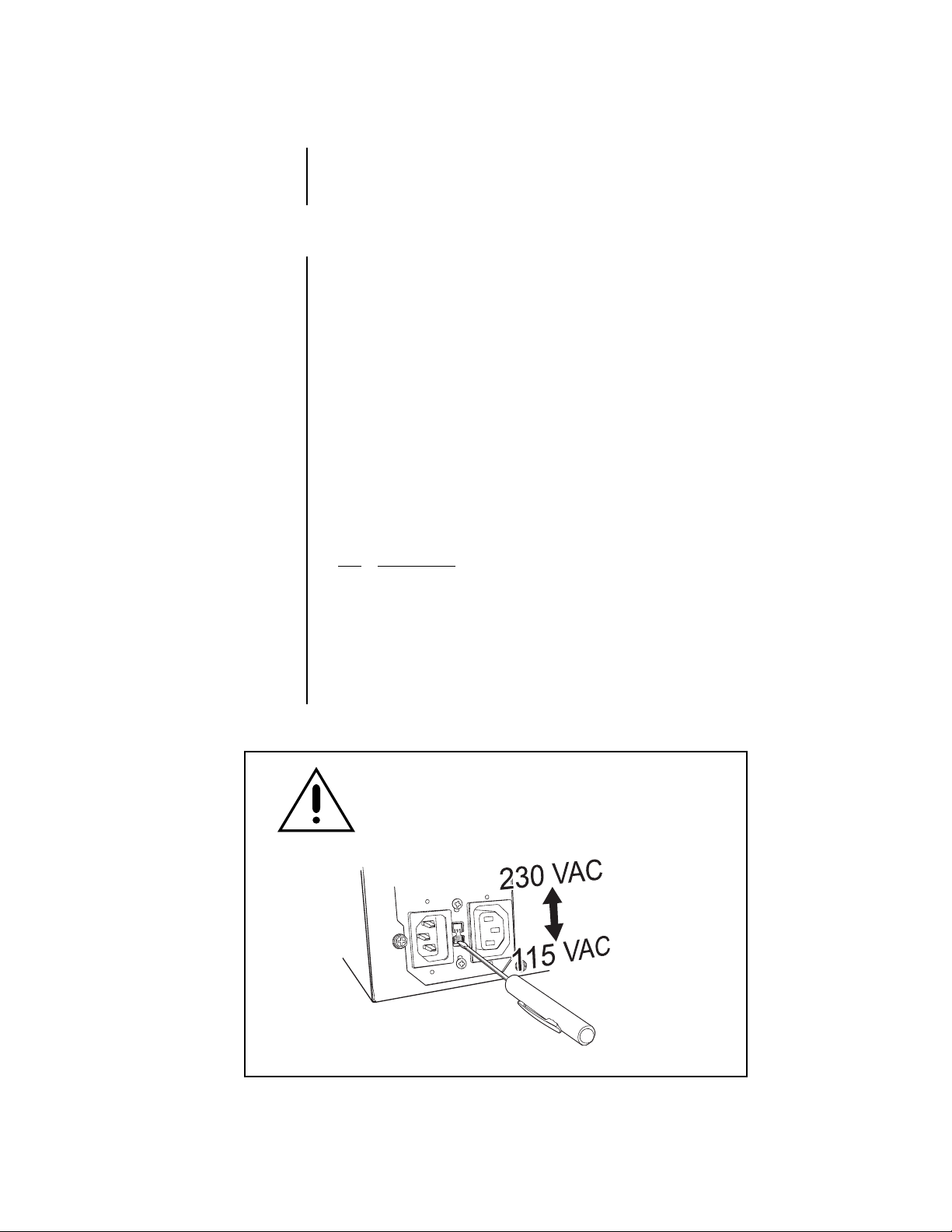
Connecting Power source to System Using 110V power source. Make sure power select
switch set to 115V(110V use)
Using 220V power source Make sure power select switch set to 230V(220V use)
NOTICE: For U.S.A and Canada regions; use only UL listed CSA labeled detachable
power cord, 3-conductor, 18 AWG, SVT or SJT type, plug rounding typeparallel blade,
cord connector body-IEC 320 style to mate with appliance inlet on product.
To reduce the risk of fire, use only No.26 AWG or larger telecommunications line cord.
IMPORTANT The only way to disconnect power completely is to unplug the power cord.
Make sure at least one end of the power cord is within easy reach so that you can unplug
the computer when you need to.
CAUTION: DANGER OF EXPLOSION IF BATTERY IS INCORRECTLY RE-
PLACED. REPLACE ONLY WITH THE SAME OR EQUIVALENT TYPE RECOMING TO THE MANUFACTURER’S INSTRUCTIONS.
ATTENTION: IL Y A DANGER D’EXPLOSION S’IL Y A REMPLACEMENT INCORRECT
DE LA BATTERIE. REMPLACER UNIQUEMENT AVEC UNE BATTERIE DU MENE TYPE
OU D’UN TYPE RECOMMANDE PAR LE CONSTRUCTEUR. METTRE AU REBUT LES
BATTERIES USAGEES CONFORMENENT AUX INSTRUCTIONS DU FABRICANT.
MENDED BY THE MANUFACTURER. DISCARD USED BATTERIES ACCORD-
Pelco Manual C682M-E (11/01) 5
DESCRIPTION
The DX7000 Series are high-quality digital video recorders (DVR) that combine the functions
of a recorder and multiplexer into a product with versatile recording and playback functions.
The units are capable of dual operation and can record and play back video at the same time.
All models have an input signal of 120/230 VAC and are NTSC/PAL compatible.
MODELS
DX7008-030 Eight-channel digital video recorder, 30 GB hard drive space
DX7008-060 Eight-channel digital video recorder, 60 GB hard drive space
DX7008-120 Eight-channel digital video recorder, 120 GB hard drive space
DX7008-180 Eight-channel digital video recorder, 180 GB hard drive space
DX7008-240 Eight-channel digital video recorder, 240 GB hard drive space
DX7008-300 Eight-channel digital video recorder, 300 GB hard drive space
DX7008-360 Eight-channel digital video recorder, 360 GB hard drive space
DX7008-420 Eight-channel digital video recorder, 420 GB hard drive space
DX7008-480 Eight-channel digital video recorder, 480 GB hard drive space
DX7016-060 Sixteen-channel digital video recorder, 60 GB hard drive space
DX7016-120 Sixteen-channel digital video recorder, 120 GB hard drive space
DX7016-180 Sixteen-channel digital video recorder, 180 GB hard drive space
DX7016-240 Sixteen-channel digital video recorder, 240 GB hard drive space
DX7016-300 Sixteen-channel digital video recorder, 300 GB hard drive space
DX7016-360 Sixteen-channel digital video recorder, 360 GB hard drive space
DX7016-420 Sixteen-channel digital video recorder, 420 GB hard drive space
DX7016-480 Sixteen-channel digital video recorder, 480 GB hard drive space
The following accessories are supplied with the DX7000 Series DVR:
Qty Description
1 Keyboard
1 Mouse
1 RS-422 communication converter, includes power adapter
1 9-pin to 25-pin adapter
2 Power cables (1 USA standard and 1 European standard)
2 Keys for front panel
1 Microsoft Windows® 98 CD
1 DX7000 Remote Site Software CD
4 Mounting screws
WARNING
This product is factory set to operate on 115 VAC.
For 230 VAC operation, move the switch to the 230 VAC
position
6 Pelco Manual C682M-E (11/01)
before applying power
to the unit.
01204
INSTALLATION
00589
NOTE:
Set the PAL/NTSC
Switch to the proper setting
for your application. Refer to
7
.
NOTE:
An UPS (Uninterrupted Power Supply) is not
supplied with the DVR.
If required, Pelco recommends a device with the
following specifications:
Capacity –
350 VA, 210 watts
Output voltage –
115 V ± 8% (on battery)
Frequency range –
47 Hz to 63 Hz
Place the DVR on any flat surface (desk or table) or install in any standard 19-inch (48.26 cm)
wide console or rack configuration.
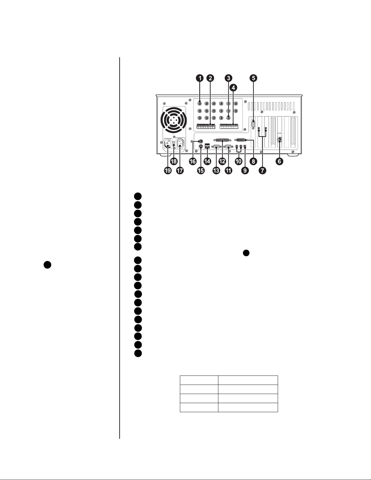
Figure 1. Rear View of Back Panel
1 Camera Inputs – Refer to Table A for video coaxial cable distances.
2 Alarm Inputs
3 Analog Monitor Output
4 Relay Outputs
5 PC Monitor Output
6 LAN Port (Internet or TCP/IP)
7 NTSC/PAL Selection Switches – Setting must correspond with the software
setup for NTSC/PAL. Refer to Figure 6, item 2 .
8 Joystick Port (Not used)
9 Microphone Jack (Not used)
10 Audio IN/OUT (Not used)
11 COM 2 Serial Port – Connection for optional external modem.
12 Printer Port
13 COM 1 Serial Port – RS-422 two-wire control output; refer to Figure 2.
14 USB Connection – For optional USB device (CD-RW).
15 Keyboard (PS/2)
16 Mouse (PS/2)
17 AC Power Output
18 115/230 VAC Power Switch
19 AC Power Input
Table A. Video Coaxial Cable Requirements
Cable Type* Maximum Distance
RG59/U 750 ft (229 m)
RG6/U 1,000 ft (305 m)
RG11/U 1,500 ft (457 m)
* Minimum cable requirements:
75 ohms impedance
All-copper center conductor
All-copper braided shield with 95% braid coverage
Pelco Manual C682M-E (11/01) 7
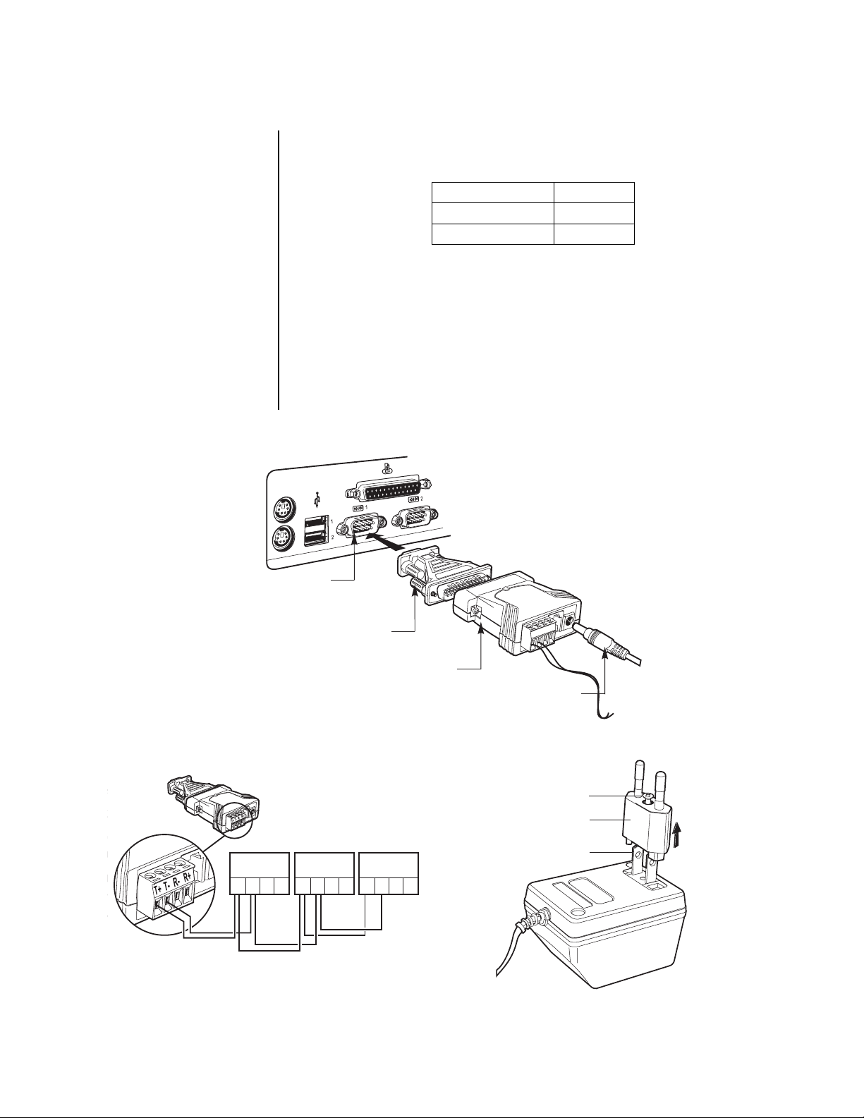
TWO-WIRE CONTROL SYSTEM INSTALLATION
NOTE:
The PTZ must be
set to accept ‘D’ protocol
control. For information on
setting the receiver address
for D-type control, refer to
the documentation supplied
with the PTZ equipment.
BACK OF DX7000
1. Connect the control wires from the receiver to the RS-422 converter. The DX7000 can
support up to 16 PTZ devices. To connect more than one PTZ to the system, refer to
Figure 3.
RS-422 Converter Receiver
TX+ RX+
TX- RX-
2. Set the DTE/DCE switch located on the bottom of the converter to DCE.
3. Plug the RS-422 converter into the 9-pin to 25-pin adapter.
4. Plug the pin converter into the COM 1 Port.
5. Attach the power adapter to the RS-422 converter.
6. Plug power adapter into a power source. The standard European plug is attached to
the power adapter. To convert the adapter to the USA standard loosen the Phillips
head screw and remove the European plug (refer to Figure 4).
COM 1 PORT
PIN CONVERTER
Figure 2. Two-Wire Control System Installation
PTZ
RX RX TX TX
+-+-
SUPPORTS UP TO 16 PTZ
MAXIMUM: 4,000 FEET (1,219 M)
RXTX TX
RX
+
PTZ
-+-
RS-422 ADAPTER
PTZ
THE LAST PTZ
TERMINATE
RX RX TX TX
+-+-
01198
POWER ADAPTER
PHILLIPS HEAD SCREW
EUROPEAN STANDARD
ADAPTOR
USA STANDARD
01194
00963
Figure 3. Multiple PTZ Installation
Figure 4. Power Adapter Plug for the RS-422 Converter
8 Pelco Manual C682M-E (11/01)
PROGRAMMING
00582
Turn the system power ON; the Main Screen (DISPLAY mode) appears.
DISPLAY MODE
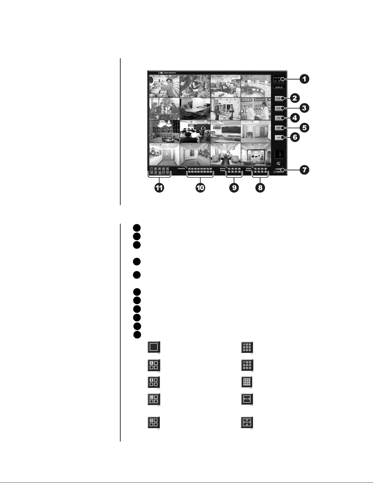
Figure 5. Display Mode
1 Date and Time Indicator – Displays current date and time.
2 SEARCH Button – Plays back and search recordings by date and time.
3 SETUP Button – Programs camera settings, customize a recording schedule, set
up multiple password levels, and establish pan and tilt protocol.
4 PTZ Control Button – Controls pan, tilt, and zoom functions. Sets patterns, tours,
and presets.
5 Copy Button (Backup) – Only appears if CD-RW software and CD-RW drive are
installed.
6 Exit – Closes DX7000 program.
7 HDD Storage Indicator – Displays percentage of used hard disk storage space.
8 Activate Relay – Turns connected relay ON/OFF.
9 Alarm Status Display – Turns button color yellow when an alarm has been activated.
10 Motion Detection Status – Turns button color blue, indicating motion is detected.
11 Screen Division
Single camera display Displays cameras 1-9
Quad display, cameras 1-4 Displays cameras 10-16
Quad display, cameras 5-8 Displays all 16 cameras
Quad display, cameras 9-12 Sequencing mode – Sequence us-
ing single, four, or nine camera displays.
Quad display, cameras 13-16 Full-screen display – Removes
menu bars from display. Click the
right mouse button to return to
previous screen display.
Pelco Manual C682M-E (11/01) 9
DX7000 SYSTEM SETUP
1
2
3
4
01177
To setup the DX7000 Digital Video Recorder use the left mouse button and click on the
SETUP button located in the DISPLAY mode.
CAMERA SETUP
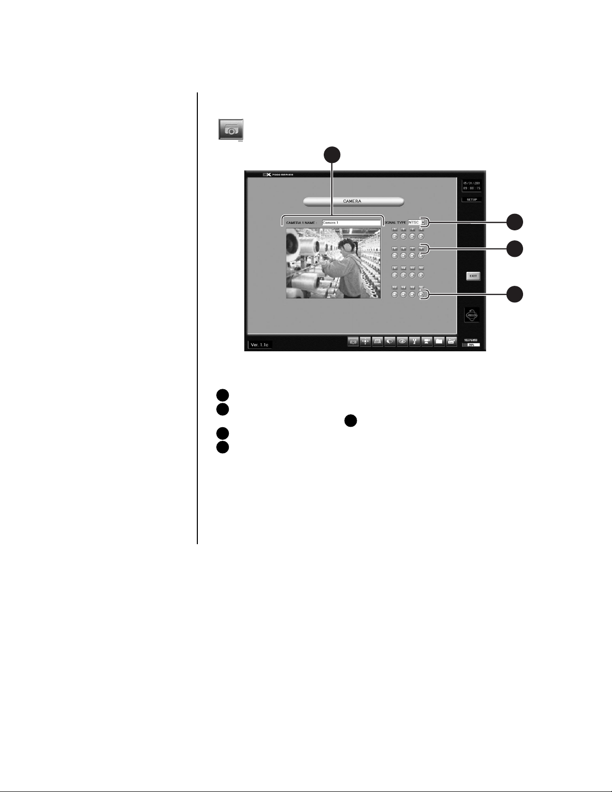
Figure 6. Channel Setup Menu
1 CAMERA NAME Box
2 SIGNAL TYPE – Selection must correspond with the NTSC/PAL selection switch
setting. Refer to Figure 1, item 7 .
3 CAMERA ENABLE Button
4 CAMERA SELECTION Button
Use the following steps to set up a camera site.
1. Click the CAMERA ENABLE button to enable a camera for setup.
2. Click the CAMERA SELECTION button (located above the CAMERA ENABLE button);
the camera scene appears in the Camera Viewing Window.
3. Enter the location of the camera in the CAMERA NAME box.
10 Pelco Manual C682M-E (11/01)
COLOR SETUP
1
2
3
4
5
67
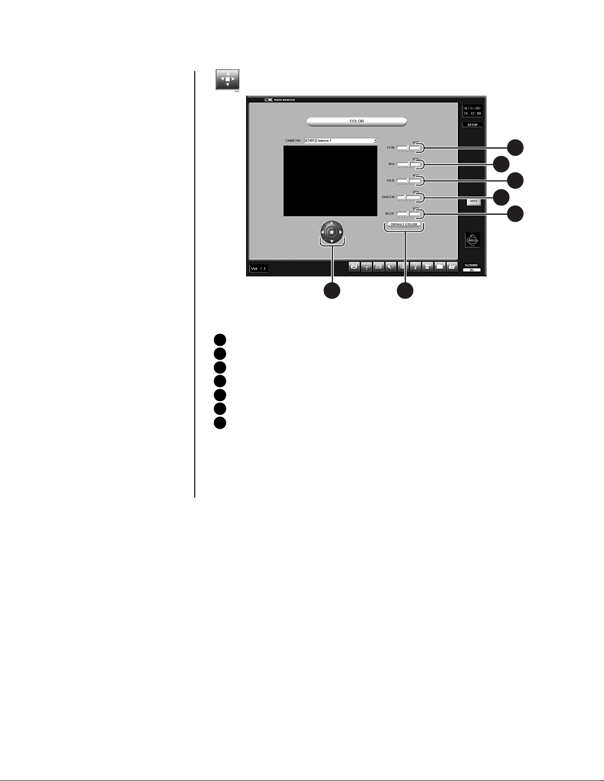
Figure 7. Color Setup Menu
1 CON – Adjusts the CONTRAST of the viewed and recorded scene.
2 BRI – Adjusts the BRIGHTNESS of the viewed and recorded scene.
3 RED – Adjusts the RED level of the viewed and recorded scene.
4 GREEN – Adjusts the GREEN level of the viewed and recorded scene.
5 BLUE – Adjusts the BLUE level of the viewed and recorded scene.
6 DEFAULT COLOR – Return all level settings to their defaults.
7 Image Alignment Buttons – Moves the image up, down, left, and right within a
channel frame to align multi-screen images.
If required, adjust the level settings of the picture.
1. Select a camera by scrolling through the selections in the CHANNEL box.
2. Adjust the viewed image using the level settings.
3. Align image in the image frame using the Image Alignment buttons.
00959
Pelco Manual C682M-E (11/01) 11
SCHEDULE SETUP
9
1 2
3
4
5
8 7
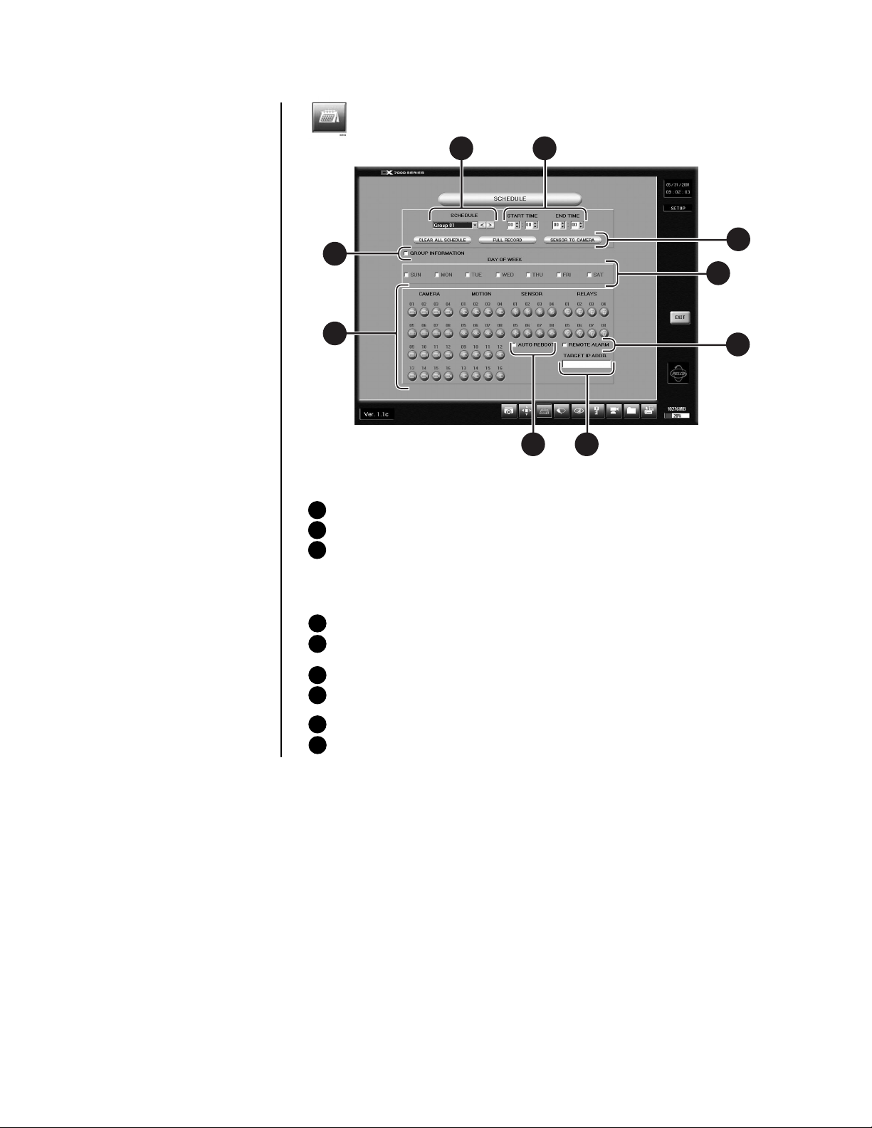
Figure 8. Schedule Setup Menu
1 GROUP (01-24) – Selects group to be scheduled.
2 Sets START TIME and END TIME for recording group.
3 Schedule Selection Buttons
CLEAR ALL SCHEDULE – Clears all GROUP (1-24) schedules.
FULL RECORD – Adds all cameras and days to GROUP 1.
SENSOR TO CAMERA – Automatically selects the camera sensor for a GROUP in
a one-to-one ratio (Camera 1, Sensor 1, Group 1).
4 DAY OF WEEK – Selects the days of the week a selected GROUP will record.
5 CAMERA, MOTION, SENSOR, AND ALARM Buttons – Selects the camera,
recording triggers, and relay outputs for the selected GROUP.
6 REMOTE ALARM – Notifies remote site if alarm is triggered.
7 TARGET IP ADDRESS – Inputs address of remote site. Use with Emergency
Agent software.
8 AUTO REBOOT – Sets the day and time system will reboot.
9 GROUP INFORMATION – Lists schedule conflicts between groups.
6
01201
12 Pelco Manual C682M-E (11/01)

Evaluate the flow of motion at the surveillance site before programming a schedule. A recording schedule can consist of one of the following modes and/or a combination of all modes:
NORMAL – Continuous recording recommended for surveillance areas with a
lot of movement.
MOTION – Saves disk space; records only when motion is detected.
SENSOR – Saves disk space; records only when an alarm is activated.
Example Schedule 1
Record 4 cameras with motion detection from Monday to Friday,
8:00 AM - 6:00 PM; Saturday 8:00 AM - 2:00 PM; and no recording on Sunday.
1. Select GROUP 01 and set START TIME to 8:00 and END TIME to 18:00.
2. Check MON, TUE, WED, THU, and FRI in the DAY OF WEEK section.
3. Select 01, 02, 03, and 04 in the CAMERA section.
4. Select 01, 02, 03, and 04 in MOTION section.
5. Select GROUP 02 and set the START TIME to 8:00 and END TIME to 14:00.
6. Check SAT in the DAY OF WEEK section.
7. Select 01, 02, 03, and 04 in CAMERA section.
8. Select 01, 02, 03, and 04 in MOTION section.
9. Select GROUP 03 and set END TIME at 8:00.
Example Schedule 2
Record continuously all week. When a signal input is received from sensor 1,
camera 1 starts recording and relay 1 starts operating. A signal input from
sensor 2 starts cameras 2 and 3 recording.
1. Select GROUP 01 and set START TIME to 0:00 and END TIME to 0:00.
2. Check SUN, MON, TUE, WED, THU, FRI, and SAT in the DAY OF WEEK
3. Select 01 in CAMERA and 01 in SENSOR and 01 in RELAY.
4. Select GROUP 02 and set START TIME to 0:00 and END TIME to 0:00.
5. Check SUN, MON, TUE, WED, THU, FRI, and SAT in the DAY OF WEEK.
6. Select 02 and 03 in CAMERA and 02 in SENSOR
Pelco Manual C682M-E (11/01) 13
SPEED SETUP
1
11
2
3
4
10
5
6
9
8 7
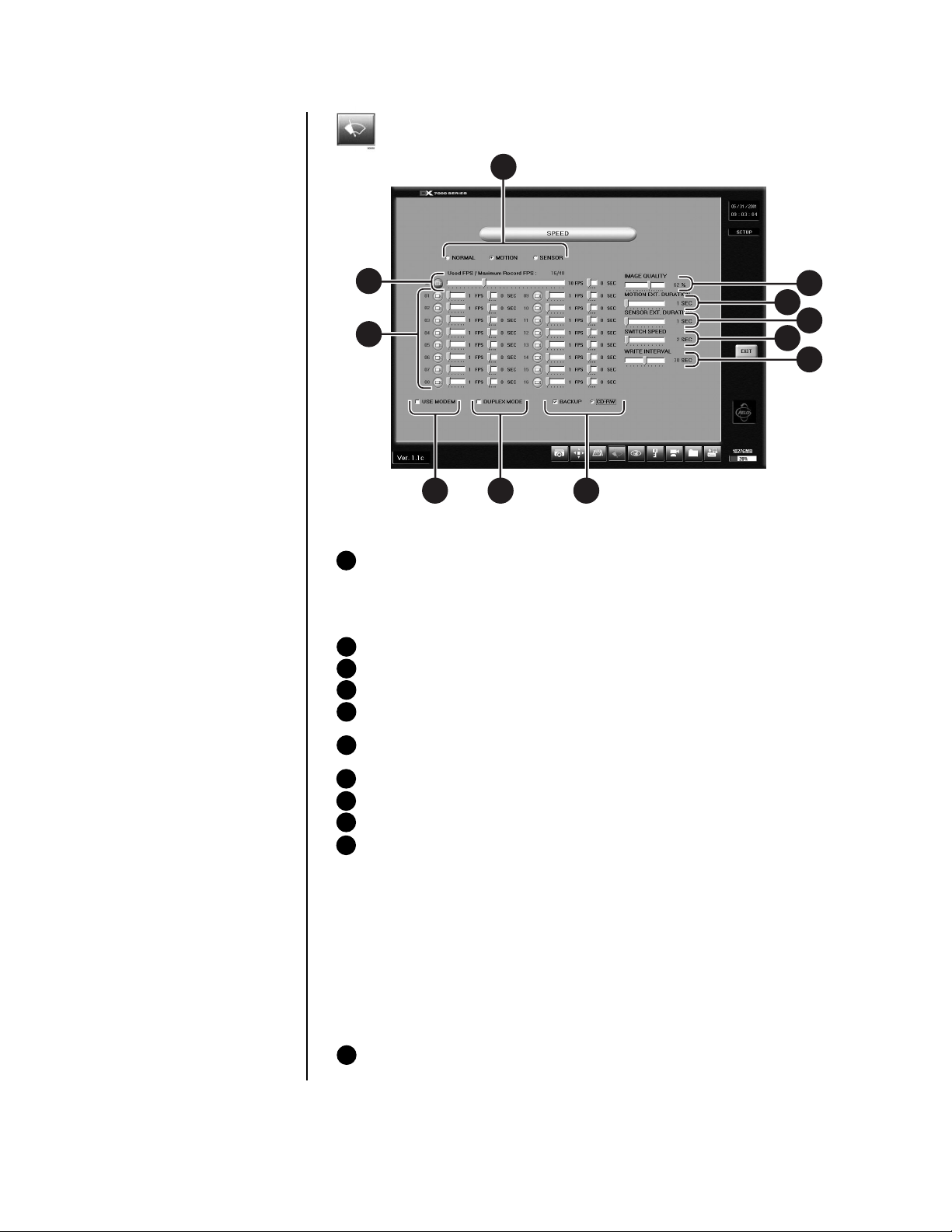
Figure 9. Speed Setup Menu
1 RECORDING SPEED MODE
a. NORMAL – Sets recording speed for continuous recording.
b. MOTION – Sets motion detection and pre-alarm recording speeds.
c. SENSOR – Sets sensor detection and pre-alarm recording speeds.
2 IMAGE QUALITY – Sets the compression size of the recorded image.
3 MOTION EXT. DURATION – Records time after motion is detected.
4 SENSOR EXT. DURATION – Records time after a sensor is triggered.
5 SWITCH SPEED – Sets the sequencing time between cameras connected to moni-
tor output.
6 WRITE INTERVAL – Determines how long images are stored in the buffer before
written to the hard drive.
7 BACKUP – Only available when backup device is installed.
8 DUPLEX MODE – Records and plays back recordings at the same time.
9 USE MODEM – Only available if modem is recognized.
10 RECORDING AND PRE-ALARM FUNCTION SPEEDS
01203
a. Recording Speed: Controls the recording rate of each camera separately by ad-
justing the control bar for each individual camera. The total available fps for all
cameras varies per mode setup.
In Duplex Mode the maximum recording speed is 60 fps.
In Simplex Mode the maximum recording speed is 160 fps.
b. Pre- Alarm Function: You can program the pre-alarm function for motion and sen-
sor recording modes. When event (motion or sensor) is detected, images are recorded for the specific duration (5 seconds maximum per camera) before an
event happens.
11 A – Average recording rate for all cameras (1 through 16). All cameras record at the
same fps.
14 Pelco Manual C682M-E (11/01)
MOTION DETECTION SETUP
1
2
3
4
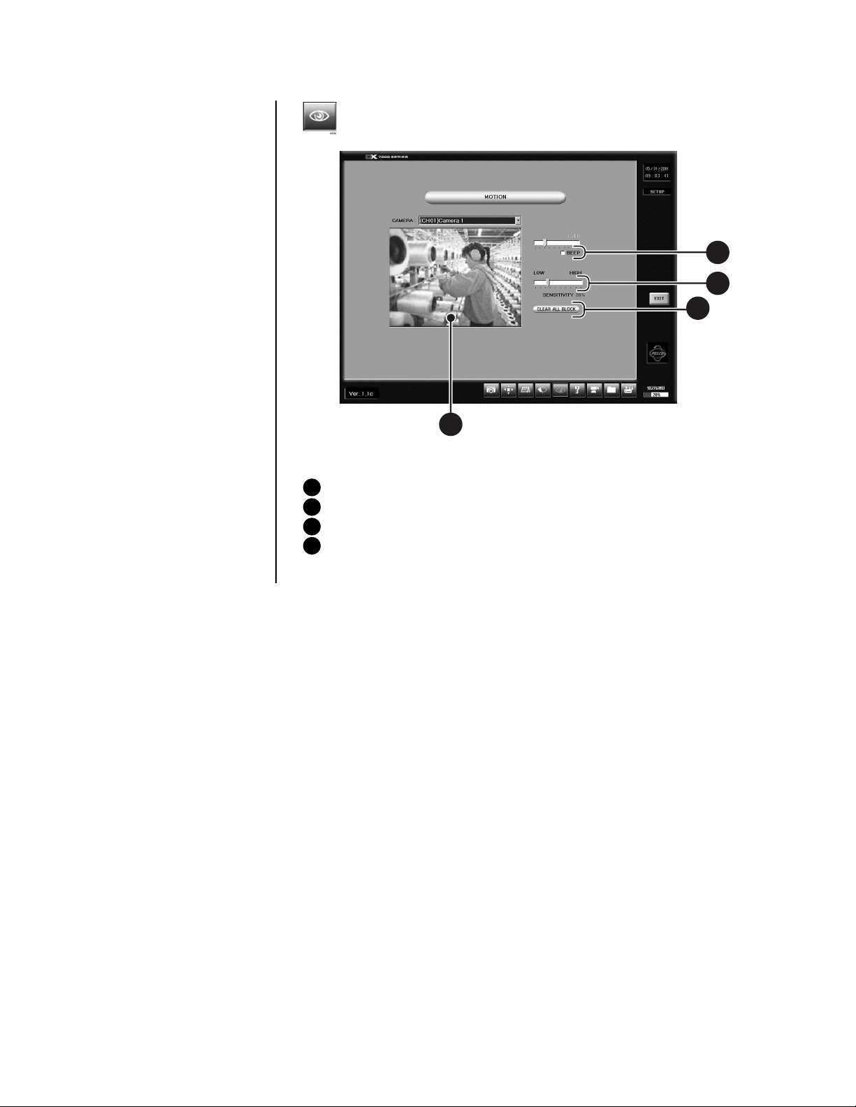
Figure 10. Motion Detection Setup Menu
1 BEEP – Beeps when motion is detected.
2 SENSITIVITY – Adjusts the sensitivity of the detection areas.
3 CLEAR ALL BLOCK – Deletes all motion detection area blocks.
4 Motion Detection Area – To select a detection area move the pointer to the desired
area. Hold down the left mouse button and drag over the area. Release the left mouse
button to end selection. A maximum of 10 detection areas can be set per camera.
01192
Pelco Manual C682M-E (11/01) 15
PASSWORD SETUP
2
1
5
3
4
01195
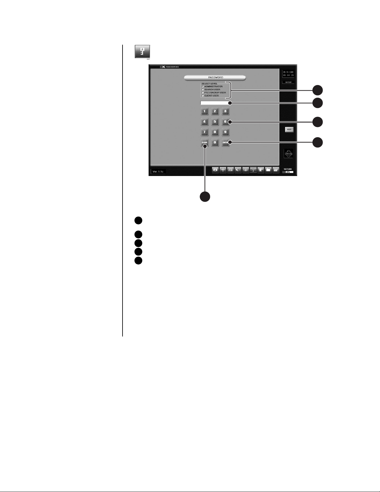
Figure 11. Password Setup Menu
1 SELECT LEVEL – Levels include Administrator, Search User, PTZ/Backup User, and
Client User.
2 INPUT AREA – Password input window.
3 NUMBER BUTTONS – Use number buttons to input password.
4 ENTER – Select to apply password to level.
5 CLEAR – Clears password input area.
To set a password:
1. Select the level.
2. Press the number buttons to input a password.
3. Click the ENTER button to apply the password input.
To clear a password:
1. Select the level.
2. Press the CLEAR button.
3. Click the ENTER button to apply the password input.
16 Pelco Manual C682M-E (11/01)

PAN & TILT SETUP
1
01197
Figure 12. Pan and Tilt Protocol Menu
1 Select pan and tilt protocol by scrolling through the selections in the RX TYPE box.
QUIT TO EXPLORER
The DX7000 uses a Window’s based operating system. To set a network address, add
hardware, or change clock settings click the Quit To Explorer button.
When exiting Windows Explorer the message “System will be shutdown” appears. Select
cancel to return to the DX7000 system DISPLAY mode.
Do not press OK. Selecting OK will turn the system off. To start the system:
1. Open the front panel of the DVR.
2. Press and hold the power switch down until the LED turns green.
IMPORTANT
Consult your network administrator to avoid possible network conflicts and to
obtain the information required to setup a network address.
UPDATE PROGRAM
00964
To update system software click the Update Program button and follow the on-screen
instructions.
Pelco Manual C682M-E (11/01) 17

OPERATION
RECORDING STATUS
HDD STORAGE INDICATOR
VIEW
The colored circle located to the right of the on-screen camera title indicates the recording
status of the camera. RED indicates that the camera is recording continuously. If the circle
is BLUE, camera recording was triggered by motion detection. YELLOW indicates sensor
input recording, and a CLEAR circle means the camera is not currently recording.
The DX7000 DVR automatically overwrites recorded data when the hard disk drive reaches
maximum storage capacity. When the HDD Storage Indicator displays 99%, the disk drive
is full. Recording continues by overwriting recorded data stored at the beginning of the HDD.
It is not necessary to use the screen division buttons located in the lower left corner of the
screen to change the camera view. You can use the left and right mouse buttons to instantly view a single camera or remove the menu bars from the display.
To change screen view:
1. Move the cursor to the desired camera view and click with the left mouse button.
A single view of the selected camera appears.
2. To switch to full screen view (remove menu bars from the display), click the right
mouse button on the screen. Click the right mouse button one more time to return to
the previous view.
3. Click the left mouse button to return to the multiple-screen view.
PTZ CONTROL MODE
To operate pan/tilt/zoom functions on controllable systems do the following:
1. Select a camera.
a. Move the cursor to a camera screen view and click the left mouse button.
b. A single camera view appears on the screen and the camera number (1 through 16)
appears in the center of the pan and tilt control (refer to Figure 13).
2. Use the buttons to pan left and right.
3. Use the buttons to tilt up and down.
4. If required use the FOCUS settings (+/-) to obtain the clearest picture.
5. Use the ZOOM settings (+/-) to zoom far/near.
▲
▼
▲
▼
LEFT
UP
RIGHT
CAMERA
DOWN
00949
Figure 13. PTZ Controls
18 Pelco Manual C682M-E (11/01)

PATTERN
A pattern is a user-defined, viewable camera path with a definite beginning and end.
The pattern can consist of any standard pan and tilt or lens commands. Once defined the
pattern is easily activated with the press of an on-screen menu button. The pattern will run
continuously until it is deactivated with another press of the menu button.
How to Program a Pattern
1. Click the PTZ button in the DISPLAY Mode. The PTZ Mode appears.
2. Select a camera.
3. Click on P-SET and move the camera through a series of movements using the pan
and tilt, zoom, and focus commands.
4. To stop programming the pattern, reclick the P-SET button.
5.
To run the pattern, click the P-RUN button. To stop the pattern, reclick the P-RUN button.
PRESETS
A preset is a user-defined camera position using pan and tilt, zoom, and focus commands.
The DX7000 Series DVR has programming capacity for 12 preset locations.
How to Program A Preset
1. Click the PTZ button in the DISPLAY Mode. The PTZ Mode appears.
2. Click the left mouse button on PRESET.
3. Select a camera by moving the cursor to the desired camera view and clicking the left
mouse button.
4. Move the camera to a desired position.
3. Click the SET button to turn it ON.
5. Click a preset button 1-12. To continue setting presets move the camera and click another preset button.
6. Click the SET button to stop programming preset positions.
NOTE:
The selected camera is indicated by the number displayed in the center of
the PTZ controls.
How to Move to a Preset
1. Click the MOVE button.
2. Click a preset button 1-12. The camera moves to the programmed preset position.
How to Clear a Preset
1. Click the CLEAR button.
2. Click a preset button 1-12.
Pelco Manual C682M-E (11/01) 19

PRESET TOURS
A preset tour is a programmed sequential execution of preset positions.
How to Program a Preset Tour
1. Click the PTZ button in the DISPLAY Mode. The PTZ Mode appears.
2. Click the left mouse button on PRESET.
3. Select a camera by moving the cursor to the desired camera view and clicking the left
mouse button.
4. Click the TOUR button to turn it ON.
3. Click the SET button to turn it ON.
5. Click preset buttons in any sequential order to program a tour.
6. To stop programming the preset tour, click the SET button and then the TOUR button.
How to Run A Preset Tour
1. Click the PTZ button in the DISPLAY Mode. The PTZ Mode appears.
2. Click the left mouse button on PRESET.
3. Click the TOUR button.
4. Click the MOVE button, the preset tour starts.
5. To stop the tour click the MOVE and TOUR buttons.
How to Clear a Preset Tour
1. Click the TOUR button.
2. Click the CLEAR button. The preset tour is now cleared. A preset tour must be cleared
before a new preset tour can be programmed.
PRESET
FOR
FUTURE
USE
BUTTONS
CAMERA
01193
Figure 14. PTZ Menus
20 Pelco Manual C682M-E (11/01)

SEARCH CONTROL MODE
1 Date and Time Indicator – Displays current date and time.
2 Search Date – Displays year, month, and time of search.
3 Search Window – Flashes when system is searching through cameras.
4 Search Index Button – Shows or hides search index.
5 Exit – Exits to display mode.
6 Playback Buttons – Refer to Figure 16.
7 Backup Button – Search button for backup storage device. Only appears if CD-RW
software and CD-RW drive are installed.
8 AVI Button – Creates and saves an AVI file to a backup storage device. To view
saved AVI files use a PC Media Player that supports the AVI file format.
9 Print Button – Prints image.
10 FDD Button – Saves recorded image to 3.5-inch diskette.
11 Zoom/Contrast/Brightness – Adjusts levels for recorded image. (Use with single
display playback only.)
12 Camera – Displays camera selection buttons for search index.
13 Calendar Button – Displays calendar with recording days highlighted.
14 Camera Enable and Selection Buttons
15 Screen Division Buttons
8
13
14 1115
Figure 15. Search Control Menu
12
10
9
7
1
2
3
4
5
6
01202
Refer to the following page for instructions on how to use the Search Control mode.
Pelco Manual C682M-E (11/01) 21

SELECT DATE AND TIME
1. Enter the year and month in the SEARCH DATE area of the menu. Click the up or
down arrow buttons to make a selection.
2. Enter the hour and minute in the SEARCH DATE area of the menu. Click the arrow
buttons up or down to make a selection.
3. Click the CALENDAR BUTTON.
4. The calendar menu appears in the lower left-hand corner of the screen.
5. Dates with recordings are highlighted with a yellow circle. Click a highlighted date.
6. Use the playback buttons to review a recording. Refer to Figure 16.
PLAYBACK
PREVIOUS IMAGE
GO TO THE FIRST IMAGE
RECORDED ON HDD
FAST PLAYBACK
NEXT IMAGE
STOP
GO TO LAST IMAGE
RECORDED ON HDD
00953
Figure 16. Playback Control Buttons
INDEX SEARCH
1. Click the CAMERA SELECTION button; refer to Figure 15. The camera buttons appear.
2. Click the INDEX SEARCH button; the Index Data List appears.
3. Select the event type (motion or sensor) to search. The EVENT type is located at the
bottom of the Index Data List.
4. Enter the START TIME and END TIME of search.
5. Click on a CAMERA button to select a camera. Only one camera can be index
searched at a time. Depending on the amount of data, it may take several minutes
before an Index List is displayed.
6. Double click on one of the data files to display the recorded image.
NOTE:
An Index Data List box can contain 32,000 search results. If the index search
results in more than 32,000 results, the system will automatically start writing to the
next list box. The DX7000 supports 10 list boxes.
22 Pelco Manual C682M-E (11/01)

BACKUP TO 3.5-INCH DISKETTE
1. Press the CAMERA SELECTION button.
2. Disable all cameras in search mode. FDD backup cannot be done when the viewing
screen is divided.
3 Select one camera.
4. Click the FDD button. The BACKUP window appears.
5. Select how many images will be saved. The total number of copies is limited to
30 images at one time.
6. Select file type (BMP or JPG).
7. Click on OK.
PRINT IMAGE
1. Press the CAMERA SELECTION button.
2. Disable all cameras in search mode. Printing an image cannot be done when the
viewing screen is divided.
3 Select one camera.
4. Click the PRINT button. The PRINT window appears.
5. Select how many images will be printed. The total number of images that can be
printed at one time is limited to 30 images.
6. Click on PRINT.
CD-RW SEARCH
Search button for a backup storage device only appears in the Search Mode if CD-RW software and a CD-RW drive are installed.
1. Click the Backup search button.
2. Click the CALENDAR BUTTON.
3. The BACKUP SEARCH menu appears in the lower left-hand corner of the screen.
4. Use the playback buttons to review a recording. Refer to Figure 16.
REMOTE VIEWING
Live and recorded video can be viewed at a remote location using DX7000 Series Remote
Site Software. A CD that contains the remote site software is included with the DX7000.
To install and operate the remote site software refer to the
this manual.
Remote Site Software
section of
Pelco Manual C682M-E (11/01) 23

REMOTE SITE SOFTWARE
01199
DESCRIPTION
INSTALLATION
IMPORTANT:
setup for the Remote User
Software:
– 32 bit
– Resolution 1024 x 768
Screen
Free remote site software is included with the DX7000 to provide remote site viewing of live
and recorded video. The software is compatible with Windows 98 and Windows 2000.
To install the remote users software:
1. Start Windows 98 or Windows 2000.
2. Close all programs, including any anti-virus programs.
3. Insert the Remote Users Software CD into the CD-ROM drive.
4. The Windows 98 Setup wizard starts. Follow the instructions that appear.
5. The DX7000 Series software installation program appears.
a. Install Microsoft Direct X 7.0.
b. Install the Remote Client program.
c. Restart the computer.
The remote site software
may not be compatible with
your video card. For best
results Pelco recommends
the following VGA cards:
•ATI RAGE 128
•ATI RAGE 128Pro
• RIVA TNT2 Model 64/
Model 64 Pro
• GeForce2 MX 400
• S3 PCI Card
• Inter 82815 Graphics
Controller
•SAVAGE4
• Any video card utilizing
the SAVAGE PRO chip
set
Figure 17. DX7000 Series Remote User Software Installation Menu
24 Pelco Manual C682M-E (11/01)

REGISTERED SITE SETUP
1
2
3
4
5
6
7
10 8
Figure 18. Setup Screen
1 Date and Time Indicator – Displays current date and time.
2 SITE NAME – Enters the name of the site.
3 ADDRESS – Inputs the IP address or phone number of site.
4 PASSWORD – Use only if the DX7000 registered site is CLIENT USER password
protected. The password must be the same as the registered site password for
CLIENT USER.
5 SWITCH SPEED (Sequencing speed) – Set the sequencing time between cameras.
6 USE BEEP – Beeps when Motion is detected.
7 EXIT – Exits setup screen.
8 OVERLAY MODE – Select NON-OVERLAY MODE if your PC video card does not
support multi-layering.
9 SELECT CHANNEL – Selects cameras to view.
10 REGISTERED SITE LIST – Creates a new registered site or deletes a registered
site from the list.
To setup a registered site:
1. Start Windows 98 or Windows 2000.
2. Click on the icon for the DX7000 Remote Client Software.
9
3. Click the SETUP button.
4. At the bottom of the REGISTERED SITE LIST, press NEW.
5. Input the site name, IP address or phone number, and client password.
6. Check the desired cameras to be displayed.
7. Click the APPLY button.
8. Click the EXIT button to finish setup.
Pelco Manual C682M-E (11/01) 25

OPERATION
1
2
3
4
9
Figure 19. Online Mode
1 Date and Time Indicator – Displays current date and time.
2 SEARCH Button – Plays back and searches recordings by date and time.
3 PTZ Control Button – Controls pan, tilt, and zoom functions.
4 CONNECT/DISCONNECT Button – Connects to the domain site or disconnects
from the domain site.
5 AVI Button – Creates and saves an AVI file to a backup storage device. To view
saved AVI files use a PC Media Player that supports the AVI file format.
6 RELAY OUTPUT – Turns relay connected to DX7000 DVR ON/OFF.
7 DOMAIN/IP ADDRESS – Displays address of domain site.
8 SITE NAME – Displays name of domain site.
678
5
01178
26 Pelco Manual C682M-E (11/01)

9 Screen Division –
Single camera display Displays cameras 1-9
Quad display, cameras 1-4 Displays cameras 10-16
Quad display, cameras 5-8 Displays all 16 cameras
Quad display, cameras 9-12
Quad display, cameras 13-16 Full-screen display – Removes
To connect to a remote site:
1. Select the site name by scrolling through the site selection window.
2. Enter DOMAIN/IP ADDRESS.
3. Click the CONNECT button.
Sequencing mode – Sequence using
single, four, or nine camera displays.
menu bars from display. Click the
right mouse button to return to previous screen display.
Pelco Manual C682M-E (11/01) 27

VIEW
It is not necessary to use the screen division buttons located in the lower left corner of the
screen to change the camera view. You can use the left and right mouse buttons to instantly view a single camera or remove the menu bars from the display.
To change screen view:
1. Move the cursor to the desired camera view and click with the left mouse button.
A single view of the selected camera appears.
2. To switch to full screen view (remove menu bars from the display), click the right
mouse button on the screen. Click the right mouse button one more time to return to
the previous view.
3. Click the left mouse button to return to the multiple-screen view.
PTZ CONTROL MODE
To operate pan/tilt/zoom functions on controllable systems, do the following:
1. Select a camera.
a. Move the cursor to a camera screen view and click the left mouse button.
b. A single camera view appears on the screen and the camera number (1 through
16) appears in the center of the pan and tilt control (refer to Figure 20).
2. Use the buttons to pan left and right.
3. Use the buttons to tilt up and down.
4. If required use the FOCUS settings (+/-) to obtain the clearest picture.
5. Use the ZOOM settings (+/-) to zoom far/near.
▲
▼
▲
▼
LEFT
UP
RIGHT
CAMERA
DOWN
00949
Figure 20. PTZ Controls
28 Pelco Manual C682M-E (11/01)

PATTERN
A pattern is a user-defined, viewable camera path with a definite beginning and end.
The pattern can consist of any standard pan and tilt or lens commands. Once defined the
pattern is easily activated with the press of an on-screen menu button. The pattern will run
continuously until it is deactivated with another press of the menu button.
How to Program a Pattern
1. Click the PTZ button in the DISPLAY Mode. The PTZ Mode appears.
2. Select a camera.
3. Click on P-SET and move the camera through a series of movements using the pan
and tilt, zoom, and focus commands.
4. To stop programming the pattern, reclick the P-SET button.
5.
To run the pattern, click the P-RUN button. To stop the pattern, reclick the P-RUN button.
PRESETS
A preset is a user-defined camera position using pan and tilt, zoom, and focus commands.
The DX7000 Series DVR has programming capacity for 12 preset locations.
NOTE:
The selected camera is indicated by the number displayed in the center of
the PTZ controls.
How to Move to a Preset
1. Click the MOVE button.
2. Click a preset button 1-12. The camera moves to the programmed preset position.
Pelco Manual C682M-E (11/01) 29

PRESET TOURS
A preset tour is a programmed sequential execution of preset positions.
How to Run A Preset Tour
1. Click the PTZ button in the DISPLAY Mode. The PTZ Mode appears.
2. Click the left mouse button on PRESET.
3. Click the TOUR button, the preset tour starts.
4. To stop the tour click the TOUR button.
PATTERN BAR PRESET BAR
FOR
FUTURE
USE
Figure 21. Pattern and Preset Bars
PRESET
BUTTONS
CAMERA
01196
30 Pelco Manual C682M-E (11/01)

SEARCH MODE
1
2
3
4
5
6
7
9 8
Figure 22. Search Mode
1 Date and Time Indicator – Displays current date and time.
2 Search Date – Selects month and year to search video.
3 Search Time – Selects the time (hour and minute) to search video.
4 Select Camera – Reviews video of selected camera.
5 Copy and Print Buttons – Saves a recorded image to a diskette, prints an image
or creates and saves an AVI file to a backup storage device.
6 EXIT – Exits search screen.
7 Playback Control Buttons – Refer to Figure 23.
8 Screen Division Buttons
9 Calendar – Dates with a yellow circle indicate that video was recorded on that day.
00955
Pelco Manual C682M-E (11/01) 31

SELECT DATE AND TIME
1. Enter the year and month in the SEARCH DATE area of the menu. Click the up or
down arrow buttons to make a selection.
2. Enter the hour and minute in the SEARCH DATE area of the menu. Click the arrow
buttons up or down to make a selection.
3. Click the CALENDAR BUTTON.
4. The calendar menu appears in the lower left-hand corner of the screen.
5. Dates with recordings are highlighted with a yellow circle. Click a highlighted date.
6. Use the playback buttons to review a recording. Refer to Figure 23.
PLAYBACK
PREVIOUS IMAGE
GO TO THE FIRST IMAGE
RECORDED ON HDD
Figure 23. Playback Control Buttons
FAST PLAYBACK
NEXT IMAGE
STOP
GO TO LAST IMAGE
RECORDED ON HDD
00953
32 Pelco Manual C682M-E (11/01)

EMERGENCY AGENT SOFTWARE
00950
Figure 24. Emergency Agent Window
Emergency Agent software alerts the remote site client of any triggered alarm at the surveillance site. When an alarm is triggered a popup widow appears on the monitor of the remote
site client. The window displays a detailed list (date and time) of all images recorded during
the alarmed event.
NOTE:
For the Emergency
Agent Software to operate
the DX7000 System at the
surveillance site must be
setup for remote alarm
operation. To setup the
DX7000 DVR for remote
alarm operation, refer to the
Schedule Setup
section of
the DX7000 Series Digital
Video Recorder Installation
and Operation Manual.
To view the transmitted images use the playback buttons located at the bottom of the Emergency Agent software window.
To install the Emergency Agent software:
1. Start Windows 98.
2. Close all programs, including any anti-virus programs.
3. Insert the Remote Users Software CD into the CD-ROM drive.
4. The Windows 98 Setup wizard starts. Follow the instructions that appear.
5. The DX7000 Series software installation program appears. Click on the Emergency
Agent software button and follow the instructions.
6. Restart the computer.
Pelco Manual C682M-E (11/01) 33

BACKUP VIEWER SOFTWARE
Use the Backup Viewer software to search images stored on backup media, DAT tape or
DVD disc.
To install the Backup Viewer:
1. Start Windows 98.
2. Close all programs, including any anti-virus programs.
3. Insert the Remote Users Software CD into the CD-ROM drive.
4. The Windows 98 Setup wizard starts. Follow the instructions that appear.
5. The DX7000 Series software installation program appears. Click on the Backup
Viewer software button and follow the instructions.
6. Restart the computer.
34 Pelco Manual C682M-E (11/01)

BACKUP VIEWER OPERATION
1
3
4
6
2
7
8
9
12
5
10
13
14 1115
01202
Figure 25. Backup Viewer
1 Date and Time Indicator – Displays current date and time.
2 Search Date – Displays year, month, and time of search.
3 Search Window – Flashes when system is searching through cameras.
4 Search Index Button – Shows or hides search index.
5 Exit – Exits to display mode.
6 Playback Buttons – Refer to Figure 16.
7 Backup Button – Search button for backup storage device. Only appears if CD-RW
software and CD-RW drive are installed.
8 AVI Button – Creates and saves an AVI file to a backup storage device.
9 Print Button – Prints image.
10 FDD Button – Saves recorded image to 3.5-inch diskette.
11 Zoom/Contrast/Brightness – Adjusts levels for recorded image. (Use with single
display playback only.)
12 Camera – Displays camera selection buttons for search index.
13 Calendar Button – Displays calendar with recording days highlighted.
14 Camera Enable and Selection Buttons
15 Screen Division Buttons
Pelco Manual C682M-E (11/01) 35

WATERMARK TOOL
The Watermark tool allows you to verify if an original image has been altered. The Watermarking
Viewer software is available on the Remote Site Software CD. To install the Watermark
Viewer:
1. Start Windows 98.
2. Close all programs, including any anti-virus programs.
3. Insert the Remote Users Software CD into the CD-ROM drive.
4. The Windows 98 Setup wizard starts. Follow the instructions that appear.
5. The DX7000 Series software installation program appears. Install the Watermark
Viewer software.
6. Restart the computer.
WATERMARK TOOL OPERATION
1. Load the Watermark Tool.
2. Click the File menu. Select the directory where the JPG or BMP image is located.
3. Select an image file.
Figure 26. The Image Has Not Been Altered
36 Pelco Manual C682M-E (11/01)

Figure 27. The Image Has Been Altered
RED FRAME
SHADING
MESSAGE
00957
There are three indications that an image has been altered:
1. A red frame around the image.
2. The image is shaded.
3. The message “Image has been altered or has not been watermarked” appears in the
lower left-hand corner of the screen.
Pelco Manual C682M-E (11/01) 37

INSTALLING THE DX7000CD (CD-RW DRIVE)
01181
1. Connect one end of the USB data cable to the CD-RW drive. Connect the other end of
the USB data cable to the USB serial port (1 or 2) located on the back panel of the
DX7000 DVR. Do not connect the power supply to the CD-RW drive at this time.
Refer to Figure 28.
BACK OF CD-RW
USB DATA
CABLE
BACK OF DX7000
USB SERIAL
PORTS
DO NOT CONNECT POWER
TO THE CD-RW DRIVE UNTIL
THE DRIVER SOFTWARE DISK
HAS BEEN INSTALLED IN THE
A:\ DRIVE OF THE DX7000 SYSTEM.
USB DATA
CABLE
01176
Figure 28. How to Connect the CD-RW Drive to the DX7000 DVR
2. Turn the DX7000 system power ON if it is OFF. From the DISPLAY mode of the
DX7000 click the SETUP button. The SETUP mode appears.
3. Click the EXIT TO EXPLORER button. Windows Explorer appears.
4. Open the door to the front panel of the DX7000. Place the Driver Installation Dis-
kette supplied with the CD-RW drive into the floppy disk drive of the DX7000.
5. Connect the power cable to the CD-RW drive. After a few seconds the Add New Hardware Wizard pops-up on the screen with the following message:
38 Pelco Manual C682M-E (11/01)

6. Click Next. The following message appears:
01182
01183
7. Select Search for the Best Driver for Your Device. Click Next and the following window
appears:
Pelco Manual C682M-E (11/01) 39

8. Select Floppy Disk Drives and click Next. The following appears:
01184
9. Accept the recommended driver by clicking Next. The following window appears:
01185
10. Click Finish.
11. After installing the driver remove the floppy disk from the A:/ drive. Exit Explorer, and
then select OK to shutdown the system.
12. Restart the DX7000 system by pushing the ON/OFF switch located on the front panel.
40 Pelco Manual C682M-E (11/01)

LOADING THE DirectCD SOFTWARE
1. From the DISPLAY mode of the DX7000 click on the SETUP button. The SETUP
mode appears.
2. Click the EXIT TO EXPLORER button. Windows Explorer appears.
3. Insert the hp cd-writer installation software – disc 1 into the CD-RW drive.
4. Select the CD-RW drive and click Setup. The Start Installation window appears.
5. Click Start Installation and follow the instructions that appear on the screen. When the
installation is finished, the system will shutdown and then automatically restart.
6. Remove the hp cd-writer installation software – disc 1 from the CD-RW
drive.
HOW TO OPERATE THE CD-RW
INITIATE DX7000 COPY BUTTON
1. From the DISPLAY mode of the DX7000 click the SETUP button. The SETUP mode
appears.
2. Click the SPEED button. The SPEED SETUP window appears.
a. Check the Backup box.
b. Check the CD-RW box.
3. UPGRADE NOW window appears.
Check the box for Do not
show this dialog again.
Click Cancel.
01200
X
01205
4. Exit the SETUP mode. The COPY button now appears in the DISPLAY mode.
Pelco Manual C682M-E (11/01) 41

PREPARING CD-RW MEDIA FOR BACKUP
NOTE:
The initial format of a CD-RW disk can take a considerable amount of time,
approximately three hours. To speed up the procedure of copying files to a backup
device, always have a formatted CD-RW disc readily available.
The Initial Formatting of CD-RW Media Using the DX7000 DVR
The following procedure is recommended for the initial format of a CD-RW disk.
1. Insert the CD-RW disc in the CD-RW drive.
2. From the DISPLAY mode of the DX7000 click the SETUP button. The SETUP mode
appears.
3. Click the EXIT TO EXPLORER button. Windows Explorer appears.
4. From Explorer open the Program Files folder.
5. Open the HP CD-Writer folder.
6. Select the Direct CD folder and click the DirectCD icon. The following appears:
01207
7. Select Next. The following appears:
01208
42 Pelco Manual C682M-E (11/01)

8. Select the CD-RW drive and click Next. The following appears:
01209
9. Type the title of the CD-RW in the place provided, and then select Finish. The following dialog box appears.
01210
10. Select OK; fast format is initiated. Approximately three minutes will pass and the
following dialog box appears:
01206
The dialog box indicates that fast format has been initiated. Although it will still take
about three hours to completely format the disc, fast format operates in the background allowing you access to the formatted portion of the disc.
11. Exit Explorer. Select Cancel when the dialog box appears to return to the DX7000
DISPLAY mode.
NOTE:
You can safely interrupt fast formatting by ejecting the disc. The disc is still
readable in other CD-RW drives, but you cannot write data to it until formatting is
complete. When you re-insert the disc in a drive using HP fast format, the formatting
continues from where it left off.
Pelco Manual C682M-E (11/01) 43

BACKUP WINDOW
1
2
3
4
12
11
10
Figure 29. Backup (COPY) Window
1 SELECT DRIVE box – Lists drives with files available for backup.
2 STORED ITEMS box – Lists all files stored in the selected drive.
3 ADD button – Adds stored files to ITEMS TO BACKUP box.
4 ITEMS TO BACKUP box – Lists files selected for backup
5 CLEAR ALL button – Clears all files in the ITEMS TO BACKUP box.
6 SPACE NEEDED indicator – Shows the amount of space required to backup
selected files.
7 HIDE button – Closes the backup window.
8 FORMAT button – Use only to format a CD/RW only after the disk has been previ-
ously formatted. Refer to
section in this manual.
9 STOP button – If the backup process to the CD/RW has been initiated, the STOP
button will end the copying session.
10 BACKUP button – Starts to backup (copy) the files in the ITEMS TO BACKUP box
to the CD-RW disc.
11 DESTINATION DRIVE – Identifies the CD-RW drive and its available storage
capacity.
12 REMOVE button – Deletes selected file/files from the ITEMS TO BACKUP box.
Initial Formatting of CD-RW Media Using the DX7000 DVR
789
5
6
01180
44 Pelco Manual C682M-E (11/01)

HOW TO BACKUP (COPY) TO THE CD-RW DRIVE
1. From the DISPLAY mode of the DX7000, click the COPY button. The SETUP mode
appears.
NOTE:
Initiate DX7000 Copy Button
2. Click the COPY button. The backup window appears.
3. Select a drive from the SELECT DRIVE box. After several minutes a list of files will ap-
4. Use the left mouse button and select file/files to backup. Click the ADD button, the se-
5. To finish the backup process click the BACKUP button. The HDD indicator located at
6. To exit the backup window, select the HIDE button.
If the COPY button is not available it has not been initiated. Refer to the
section of this manual.
pear in the STORED ITEM(S) box.
lected files appear in the ITEM(S) TO BACKUP box.
the bottom right-hand corner of the screen is now labeled BACKUP, signifying that the
files are being written to the CD-RW drive (refer to Figure 30).
STORAGE INDICATOR IS NOW LABELED BACKUP
7
01179
Figure 30. Storage Indicator is now Labeled BACKUP
Pelco Manual C682M-E (11/01) 45

DX7000EM (External Modem)
CONNECT THE EXTERNAL MODEM TO THE DX7000
1. Connect the 25-pin end of the RS-232 cable (supplied with the modem) to the serial
port located on the back panel of the modem.
2. Connect other end of the RS-232 cable to the COM 2 serial port located on the back
panel of the DX7000.
3. Connect one end of the supplied telephone cable to the modem port labeled JACK.
4. Connect the other end of the cable to the telephone wall jack.
5. Set the modem DIP switches 3 and 8 to the ON position.
6. Connect one end of the supplied power adapter to the modem and the other end to a
standard AC power outlet.
BACK OF DX7000EM
POWER
BACK OF DX7000
JACK
SERIAL PORT
COM 2 SERIAL PORT
01186
Figure 31. How to Connect the External Modem to the DX7000 DVR
46 Pelco Manual C682M-E (11/01)

LOAD THE DRIVER FOR THE MODEM
01187
01188
1. From the DISPLAY mode of the DX7000, click the EXIT button. A dialog box appears.
Select Yes. The DX7000 shuts off.
2. Turn ON the modem and restart the DX7000 system by pushing the ON/OFF switch
located on the front panel.
3. The DX7000 detects the new hardware. After a few seconds the Add New Hardware
Wizard pops-up on the screen with the following message:
4. Click Next and the following appears:
Pelco Manual C682M-E (11/01) 47

5. Select Search for the Best Driver for Your Device. Click Next, the following appears:
01189
01190
01191
6. Type C:\Windows\System in the space provided. Click Next, the following appears:
7. Accept the recommended driver by clicking Next. The following window appears:
48 Pelco Manual C682M-E (11/01)

8. Click Finish, the DX7000’s DISPLAY mode appears.
9. From the DISPLAY mode of the DX7000 click the SETUP button. The SETUP mode
appears.
10. Click the SPEED button. The SPEED SETUP window appears.
a. Check the Use Modem box.
b. Check the Duplex box.
11. Exit SETUP to return to the DISPLAY mode.
Pelco Manual C682M-E (11/01) 49

SPECIFICATIONS
ELECTRICAL/VIDEO
Input Voltage: 100-240 VAC switchable, 50/60 Hz
Signal System: NTSC/PAL
CPU & RAM
DX7008: Celeron, 128 MB
DX7016: Pentium
Resolution
NTSC: 320 x 240
PAL: 384 x 288
Compression: M-JPEG
Compressed Image Size: 52 x 240; average 6KB
Video Inputs: 8 or 16, depending on model
Video Outputs: 2 (1 SVGA, 1 analog)
Alarm Inputs: 8
Control Outputs: 8
Remote Control: Full remote control via PSTN, ISDN, TCP/IP
Pan/Tilt/Zoom Control: RS-422 interface to receivers
®
III, 128 MB
GENERAL
Operating Temperature: 41° to 104°F (5° to 40°C).
Relative Humidity: Maximum 80% non-condensing
Dimensions: 7 (H) x 17 (W) x 18 (D) inches (17.78 x 43.18 x 45.72 cm)
Unit Weight (Approximate)
DX7008-030, DX7008-060,
DX7016-060: 37.19 lb (18.87 kg)
DX7008-120, DX7016-120: 39.19 lb (17.78 kg)
DX7008-180, DX7016-180: 41.19 lb (18.68 kg)
DX7008-240, DX7016-240: 43.19.lb (19.59 kg)
DX7008-300, DX7016-300: 45.19 lb (20.50 kg)
DX7008-360, DX7016-360: 47.19 lb (21.41 kg)
DX7008-420, DX7016-420: 49.19 lb (22.31 kg)
DX7008-480, DX7016-480: 51.19 lb (23.22 kg)
(Design and product specifications subject to change without notice.)
50 Pelco Manual C682M-E (11/01)

NOTES
Pelco Manual C682M-E (11/01) 51

PRODUCT WARRANTY AND RETURN INFORMATION
WARRANTY
Pelco will repair or replace, without charge, any merchandise proved defective in material or
workmanship for a period of one year after the date of shipment.
Exceptions to this warranty are as noted below:
• Five years on FT/FR8000 Series fiber optic products.
®
• Three years on Genex
• Three years on Camclosure
CC3701H-2X, CC3751H-2, CC3651H-2X, MC3651H-2, and MC3651H-2X camera models,
which have a five-year warranty.
•Two years on standard motorized or fixed focal length lenses.
•Two years on Legacy
fixed dome products.
•Two years on Spectra
continuous motion applications.
•Two years on Esprit
• Eighteen months on DX Series digital video recorders, NVR300 Series network video
recorders, and Endura
• One year (except video heads) on video cassette recorders (VCRs). Video heads will be
covered for a period of six months.
• Six months on all pan and tilts, scanners or preset lenses used in continuous motion
applications (that is, preset scan, tour and auto scan modes).
Pelco will warrant all replacement parts and repairs for 90 days from the date of Pelco
shipment. All goods requiring warranty repair shall be sent freight prepaid to Pelco, Clovis,
California. Repairs made necessary by reason of misuse, alteration, normal wear, or accident
are not covered under this warranty.
Pelco assumes no risk and shall be subject to no liability for damages or loss resulting from
the specific use or application made of the Products. Pelco’s liability for any claim, whether
based on breach of contract, negligence, infringement of any rights of any party or product
liability, relating to the Products shall not exceed the price paid by the Dealer to Pelco for
such Products. In no event will Pelco be liable for any special, incidental or consequential
damages (including loss of use, loss of profit and claims of third parties) however caused,
whether by the negligence of Pelco or otherwise.
The above warranty provides the Dealer with specific legal rights. The Dealer may also have
additional rights, which are subject to variation from state to state.
Series products (multiplexers, server, and keyboard).
®
and fixed camera models, except the CC3701H-2,
®
, CM6700/CM6800/CM9700 Series matrix, and DF5/DF8 Series
®
, Esprit®, ExSite™, and PS20 scanners, including when used in
®
and WW5700 Series window wiper (excluding wiper blades).
™
Series distributed network-based video products.
If a warranty repair is required, the Dealer must contact Pelco at (800) 289-9100 or
(559) 292-1981 to obtain a Repair Authorization number (RA), and provide the following
information:
1. Model and serial number
2. Date of shipment, P.O. number, Sales Order number, or Pelco invoice number
3. Details of the defect or problem
If there is a dispute regarding the warranty of a product which does not fall under the
warranty conditions stated above, please include a written explanation with the product
when returned.
Method of return shipment shall be the same or equal to the method by which the item was
received by Pelco.
RETURNS
In order to expedite parts returned to the factory for repair or credit, please call the factory at
(800) 289-9100 or (559) 292-1981 to obtain an authorization number (CA number if returned
for credit, and RA number if returned for repair).
All merchandise returned for credit may be subject to a 20% restocking and refurbishing
charge.
Goods returned for repair or credit should be clearly identified with the assigned CA or RA
number and freight should be prepaid. Ship to the appropriate address below.
If you are located within the continental U.S., Alaska, Hawaii or Puerto Rico, send goods to:
Service Department
Pelco
3500 Pelco Way
Clovis, CA 93612-5699
If you are located outside the continental U.S., Alaska, Hawaii or Puerto Rico and are
instructed to return goods to the USA, you may do one of the following:
If the goods are to be sent by a COURIER SERVICE, send the goods to:
Pelco
3500 Pelco Way
Clovis, CA 93612-5699 USA
If the goods are to be sent by a FREIGHT FORWARDER, send the goods to:
Pelco c/o Expeditors
473 Eccles Avenue
South San Francisco, CA 94080 USA
Phone: 650-737-1700
Fax: 650-737-0933
REVISION HISTORY
Manual # Date Comments
C682M 4/01 Original version.
C682M-A 5/01 Added GUI software changes to manual.
C682M-B 6/01 Added PTZ control functions.
C682M-C 7/01 Added GUI software changes to manual. Added instructions for Remote Site Software.
C682M-D 10/01 Added installation instruction for the DX7000CD and the DX7000EM.
C682M-E 11/01 Added information on Overlay Mode.
® Pelco, the Pelco logo, Spectra, Genex, and Legacy are registered trademarks of Pelco. © Copyright 2001, Pelco
™ Esprit and Camclosure are trademarks of Pelco. All rights reserved.
® Windows is a registered trademark of Microsoft.
® Pentium is a registered trademark of Intel.
™ DirectCD is a trademark of Adaptec, Inc.
 Loading...