

Page 1
INSTALLATION/OPERATION
DX3100 Series
®
Digital Video Recorder
C695M-B (11/03)
Page 2

CONTENTS
Section Page
IMPORTANT SAFEGUARDS AND WARNINGS .................................................................................................................................................................. 4
DESCRIPTION ..................................................................................................................................................................................................................... 5
MODELS .................................................................................................................................................................................................................... 5
ACCESSORIES ........................................................................................................................................................................................................... 5
INSTALLATION ....................................................................................................................................................................................................................7
DX3100 REAR PANEL CONNECTIONS ...................................................................................................................................................................... 7
MOUNT THE DX3100 ................................................................................................................................................................................................ 8
CONNECT EQUIPMENT ............................................................................................................................................................................................. 8
CHANNELS AND MONITOR ...................................................................................................................................................................................... 9
RECEIVER WIRING .....................................................................................................................................................................................................9
ALARM WIRING ....................................................................................................................................................................................................... 10
NETWORK CONNECTION .........................................................................................................................................................................................10
CONNECT POWER .................................................................................................................................................................................................... 11
POWER CYCLING AND SCAN MODE OPERATION .................................................................................................................................................. 11
OPERATING AND PROGRAMMING CONTROLS ............................................................................................................................................................... 12
DX3100 FRONT PANEL CONTROLS ..........................................................................................................................................................................13
IR REMOTE CONTROLLER CONTROLS ..................................................................................................................................................................... 14
PROGRAMMING ................................................................................................................................................................................................................15
MENU STRUCTURE .................................................................................................................................................................................................. 15
SETUP MENU NAVIGATION ..................................................................................................................................................................................... 16
DX3100-IR REMOTE SYNCHRONIZATION ............................................................................................................................................................... 18
STORAGE CALCULATIONS ....................................................................................................................................................................................... 19
DX3100 CONFIGURATION ........................................................................................................................................................................................ 21
RECORDER SETUP ........................................................................................................................................................................................... 22
CAMERA SETUP .............................................................................................................................................................................................. 25
ALARM SETUP .................................................................................................................................................................................................27
NETWORK SETUP ............................................................................................................................................................................................28
SYSTEM STATUS AND UPGRADE ................................................................................................................................................................... 29
ENG/DEU/ESP/FRA/POR (LANGUAGE) ........................................................................................................................................................... 30
OPERATION........................................................................................................................................................................................................................ 31
LIVE VIEW MODE ..................................................................................................................................................................................................... 32
ON-SCREEN OVERLAY..................................................................................................................................................................................... 33
VIEWING VIDEO .............................................................................................................................................................................................. 33
SINGLE SCREEN VIEWING ..................................................................................................................................................................... 33
MULTIPLE SCREEN VIEWING ................................................................................................................................................................. 34
SEQUENCES ........................................................................................................................................................................................... 35
PLAYBACK MODE .....................................................................................................................................................................................................36
STARTING PLAYBACK MODE .......................................................................................................................................................................... 37
ACCESSING RECORDED VIDEO ....................................................................................................................................................................... 38
SWITCHING CHANNELS ................................................................................................................................................................................. 39
SEARCHING FOR SPECIFIC VIDEO ................................................................................................................................................................... 40
SEARCHING OPEN TIME FILES ....................................................................................................................................................................... 41
SEARCHING VIDEO DURING CHANGE TO DAYLIGHT SAVING TIME ............................................................................................................. 42
MPEG STRUCTURE AND FRAME OPERATIONS.............................................................................................................................................. 43
SAVING IMAGES TO FLOPPY DISKETTE ......................................................................................................................................................... 44
EVENT .............................................................................................................................................................................................................. 45
PTZ MODE ................................................................................................................................................................................................................ 46
ARROW BUTTONS: FRONT PANEL VS. REMOTE ........................................................................................................................................... 46
ZOOMING ........................................................................................................................................................................................................ 47
LENS FUNCTIONS ........................................................................................................................................................................................... 47
PTZ TROUBLESHOOTING ................................................................................................................................................................................. 47
ALARM DISPLAY ISSUES ......................................................................................................................................................................................... 48
SPECIFICATIONS................................................................................................................................................................................................................ 49
WARRANTY AND RETURN INFORMATION ...................................................................................................................................................................... 50
2 C695M-B (11/03)
Page 3

LIST OF ILLUSTRATIONS
Figure Page
1 DX3100 Front and Rear Panels .........................................................................................................................................................................6
2 DX3108 Rear View............................................................................................................................................................................................ 7
3 DX3116 Rear View............................................................................................................................................................................................ 7
4 DX3100 Series Installation ...............................................................................................................................................................................8
5 Alarm Wiring Example .................................................................................................................................................................................... 10
6 Scan Mode Engaged ....................................................................................................................................................................................... 11
7 Menu Tree ........................................................................................................................................................................................................ 15
8 Setup Menu Screen .........................................................................................................................................................................................16
9 Navigating the CAMERA SETUP Screen ......................................................................................................................................................... 17
10 DX3100-IR Remote Synchronization ............................................................................................................................................................... 18
11 Setup Menu Screen .........................................................................................................................................................................................21
12 Recorder Setup Screen ....................................................................................................................................................................................22
13 Camera Setup Screen ......................................................................................................................................................................................25
14 Alarm Setup Screen ........................................................................................................................................................................................ 27
15 Network Setup Screen .................................................................................................................................................................................... 28
16 System Status Screen ..................................................................................................................................................................................... 29
17 Language Setup Screen .................................................................................................................................................................................. 30
18 DX3100 Sample LIVE VIEW Screens ............................................................................................................................................................... 32
19 On-Screen Overlay ...........................................................................................................................................................................................33
20 Channel Selection ........................................................................................................................................................................................... 33
21 Stepping Through Screen Sets: Front Panel ................................................................................................................................................... 34
22 Stepping Through Screen Sets: IR Remote Control ........................................................................................................................................ 35
23 Opening Playback Overlay ............................................................................................................................................................................... 37
24 Playback Mode Entry Time Files...................................................................................................................................................................... 38
25 Play Back Different Channels .......................................................................................................................................................................... 39
26 Switching Channels and Time Frames ............................................................................................................................................................ 40
27 Searching DST Files ........................................................................................................................................................................................ 42
28 Event Display ................................................................................................................................................................................................... 45
29 PTZ Instructions ............................................................................................................................................................................................... 46
LIST OF TABLES
Table Page
AVideo Coaxial Cable Requirements .................................................................................................................................................................. 9
BTransmit (TX) to Receive (RX) Connections ...................................................................................................................................................... 9
C DX3100 Channel Sets ...................................................................................................................................................................................... 34
C695M-B (11/03) 3
Page 4

IMPORTANT SAFEGUARDS AND WARNINGS
Observe the following WARNINGS before installing and using this product.
1. Read these instructions.
2. Keep these instructions.
3. Heed all warnings.
4. Follow all instructions.
5. Do not use this apparatus near water.
6. Clean only with dry cloth.
7. Do not block any ventilation openings. Install in accordance with the manufacturer’s instructions.
8. Do not install near any heat sources such as radiators, heat registers, stoves, or other apparatus (including amplifiers) that produce
heat.
9. Do not defeat the safety purpose of the polarized or grounding-type plug. A polarized plug has two blades with one wider than the
other. A grounding plug has two blades and a third grounding prong. The wide blade or the third prong is provided for your safety. If
the provided plug does not fit into your outlet, consult your electrician for replacement of the obsolete outlet.
10. Protect the power cord from being walked on or pinched, particularly at the plug, convenience receptacle, and the point where it
exits from the apparatus.
11. Only use attachments/accessories specified by the manufacturer.
12. Use only with the cart, stand, tripod, bracket, or table specified by the manufacturer, or sold with the apparatus. When a cart is used,
use caution when moving the cart/apparatus combination to avoid injury from tip-over.
13. Refer all servicing to qualified service personnel. Servicing is required when the apparatus has been damaged in any way, such as
when the power supply cord or plug is damaged, liquid has been spilled or objects have fallen into the apparatus, the apparatus has
been exposed to rain or moisture, the apparatus does not operate normally, or the apparatus has been dropped.
14. Apparatus shall not be exposed to dripping or splashing, and no objects filled with liquids, such as vases, shall be placed on the
apparatus.
15. Warning: To reduce the risk of fire or electric shock, do not expose this apparatus to rain or moisture.
16. Caution: Risk of explosion exists if battery is replaced by an incorrect type. Dispose of used batteries according to the instructions
provided by the battery manufacturer.
17. To reduce the risk of shock, do not perform any servicing other than that contained in the operating instructions unless you are
qualified to do so.
18. Unless the unit meets NEMA Type 3, 3R, 3S, 4, 4X, 6, or 6P standards, it is designed for indoor use only and must not be installed
where exposed to rain and moisture.
19. Caution: The voltage rating for equipment attached to the ALARM IN, OUT terminals of the DX3100 Series should not exceed 1 A,
24 VDC.
20. The installation method and materials should be capable of supporting four times the weight of the unit and equipment.
The product and/or manual may bear the following marks:
This symbol indicates that dangerous voltage constituting a risk of electric shock
is present within this unit.
This symbol indicates that there are important operating and maintenance
CAUTION:
RISK OF ELECTRIC SHOCK.
DO NOT OPEN.
instructions in the literature accompanying this unit.
Please thoroughly familiarize yourself with the information in this manual prior to installation and operation.
4 C695M-B (11/03)
Page 5

DESCRIPTION
DX3100 digital video recorders (DVRs) combine the functions of a high-quality recorder with a multiplexer into a single unit. Both 8- and
16-channel models are available with 60, 120, or 240 GB hard drives. You can set the DX3100 to record video at either high (640 x 240) or
low (352 x 240) resolution. The DX3100 software can be upgraded through the built-in floppy disk drive (FDD) or by remote download
through a network connection. All units are capable of both NTSC and PAL formats.
MODELS
DX3108-060 Eight-channel digital video recorder, 60 GB (one 60 GB hard drive)
DX3108-120 Eight-channel digital video recorder, 120 GB (one 120 GB hard drive)
DX3108-240 Eight-channel digital video recorder, 240 GB (two 120 GB hard drives)
DX3116-060 Sixteen-channel digital video recorder, 60 GB (one 60 GB hard drive)
DX3116-120 Sixteen-channel digital video recorder, 120 GB (one 120 GB hard drive)
DX3116-240 Sixteen-channel digital video recorder, 240 GB (two 120 GB hard drives)
ACCESSORIES
The following accessories are supplied with the DX3100 Series digital video recorder:
Qty Description
1 DX3100 Series Installation/Operation manual
1 DX3100 Series Quick Start Guide
1 DX3100 Resource CD
1 DX3100RX Remote Site Software Installation/Operation manual
1 IR (infrared) remote controller
2 Power cables (1 USA standard and 1 European standard)
1 RS-232 to RS-422/RS-485 converter (including power adapter and 9-pin to 25-pin adapter)
2 DB15 to 8-BNC cable-set for looping outputs (DX3116 models only)
2 rack ears for rack-mount installation
4 rubber feet
The following accessory is optional:
DX3100IRREC External receiver for IR (infrared) remote controller
C695M-B (11/03) 5
Page 6

8-CHANNEL FRONT VIEW
8-CHANNEL REAR VIEW
16-CHANNEL FRONT VIEW
16-CHANNEL REAR VIEW
1IN23456
91011121314
OUT 9-16OUT 1-8
78MON OUT
15 16
LAN
NTSC PAL
RC
G123 4G 1 2
IN OUT ALARM
P/T/Z SERIAL
Figure 1. DX3100 Front and Rear Panels
115V
230V115V
6 C695M-B (11/03)
Page 7

INSTALLATION
DX3100 REAR PANEL CONNECTIONS
The rear views of the DX3108 and DX3116 are shown in Figures 2 and 3, respectively.
1
IN
OUT
23456
1234 56
78
78
NTSC PAL
MON OUT
G123 4G 1 2
IN OUT ALARM
115V
230V115V
LAN
RC
P/T/Z SERIAL
Figure 2. DX3108 Rear View
1IN23456
91011121314
OUT 9-16OUT 1-8
78
15 16
LAN
RC
MON OUT
NTSC PAL
P/T/Z SERIAL
G123 4G 1 2
Figure 3. DX3116 Rear View
Channel inputs: 16 for DX3116, 8 for DX3108; 8 looping outputs for DX3108
IN OUT ALARM
115V
230V115V
Monitor out BNC connector
NTSC/PAL selection switch (default is NTSC)
Alarms: 4 dry contact inputs and 2 relay outputs
AC power input (default is 115V)
Serial port (reserved)
PTZ port (PTZ control of cameras using Pelco’s P or D protocol)
RC (connection for optional external receiver for IR remote controller)
Network port (10/100BASE-TX Ethernet)
Network indicators: Red LED for connection, green LED for network activity
Looping outputs 1-8
DX3116 only: Looping outputs 9-16
C695M-B (11/03) 7
Page 8
MOUNT THE DX3100
Mount the controller on a flat surface (attach rubber feet if mounting on a flat surface) or use the provided rack ears to rack-mount the
unit. All models occupy two rack units (RU) of rack space. One RU equals 1.75 inches or 4.45 cm.
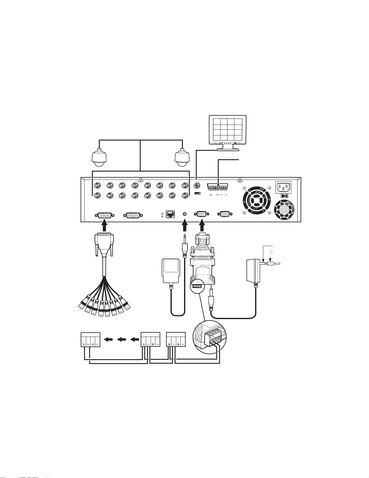
CONNECT EQUIPMENT
Use the following instructions to attach all equipment to be used with the recorder. Use Figure 4 as a visual guide for connecting various
types of equipment.
CAMERA INPUTS (1-16)
1IN23456
91011121314
78
15 16
NTSC PAL
MON OUT
MONITOR
G 1 2 3 4 G 1 2
IN OUT ALARM
ALARM (SENSOR)
INPUTS (4)
ALARM (RELAY CONTACTS)
OUTPUTS (2)
115V
230V115V
DB-15 TO
8-CHANNEL
BNC LOOPING
CABLE
Rx RxTx Tx
OUT 9-16OUT 1-8
OPTIONAL REMOTE
IR SENSOR FOR IR
CONTROLLER
Rx RxTx Tx Rx RxTx Tx
DAISY-CHAIN HOOKUP
FOR PTZ CAMERAS
LAN
RC
P/T/Z SERIAL
DX3116-XX
USA STANDARD
EUROPEAN STANDARD
ADAPTER
RS-232 TO
RS-422/RS-485
CONVERTER
RS-422
POWER
ADAPTER
PTZPTZPTZ
Figure 4. DX3100 Series Installation
8 C695M-B (11/03)
Page 9

CHANNELS AND MONITOR
Refer to Table A for video coaxial cable distances.
1. Connect video cables to the inputs on the rear of the unit.
2. If looping is desired, attach BNC monitor cables to the appropriate output BNCs (DX3108 models) or use the provided looping output
cables (DX3116 models).
3. Attach a monitor to the MON OUT BNC on the rear of the unit. This is used for programming the unit and for user operation.
RECEIVER WIRING
Table A. Video Coaxial Cable Requirements
Cable Type* Maximum Distance
RG59/U 750 ft (229 m)
RG6/U 1,000 ft (305 m)
RG11/U 1,500 ft (457 m)
*Minimum cable requirements:
75 ohms impedance
All-copper center conductor
All-copper braided shield with 95% braid coverage
Wire all camera receiver units that are to be used for PTZ operations. Note that although both Pelco P and Pelco D protocols are
recognized and can be used with the controller, you cannot mix receiver protocols on the same DX3100. Select the protocol when
programming the unit.
1. Connect the control wires from the receiver to the RS-232 to RS-422/RS-485 converter. The DX3100 can support up to 16 PTZ devices.
(Refer to Table B and Figure 4.)
Table B. Transmit (TX) to Receive (RX) Connections
RS-232 to RS-422/RS-485
Converter Receiver
TX+ RX+
TX- RX-
2. Set the DTE/DCE switch located on the bottom of the converter to DCE.
3. Plug the RS-232 to RS-422/RS-485 converter into the 9-pin to 25-pin adapter.
4. Plug the converter into the PTZ port.
5. Attach the power adapter to the RS-232 to RS-422/RS-485 converter.
6. Plug the power adapter into a power source. The standard European plug is attached to the power adapter. To convert the adapter to
the USA standard, loosen the Phillips screw and remove the European plug (refer to Figure 4).
C695M-B (11/03) 9
Page 10
ALARM WIRING
Up to four alarm inputs can be wired to the DX3100. You can also connect up to two external devices to the unit. When an alarm input is
triggered, the unit begins alarm recording. It can also activate the external devices.
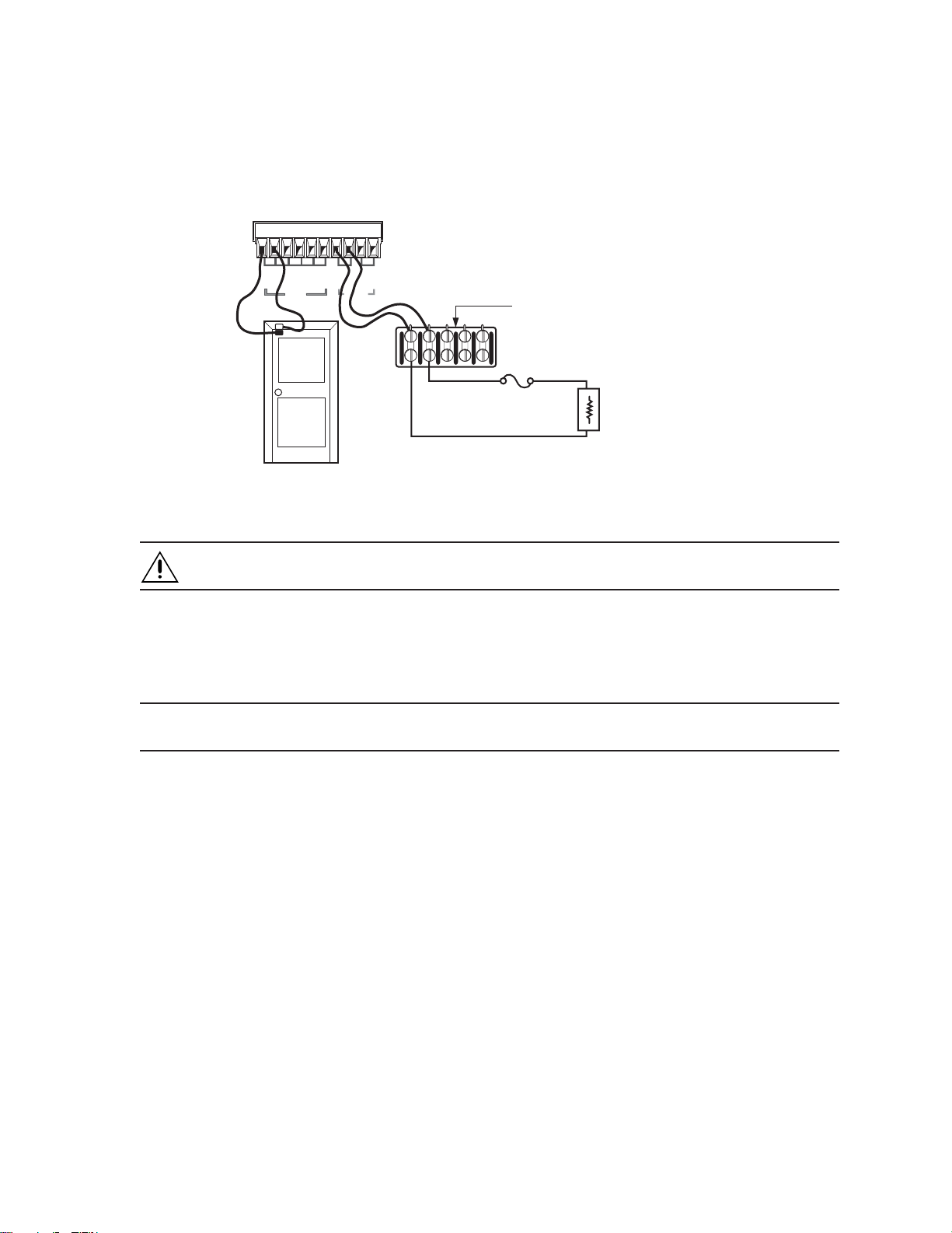
Use Figure 5 as a guide for wiring the alarm inputs and relay outputs.
G123 4G 1 2
IN OUT ALARM
WIRING
PANEL
WARNING: The alarm relay output provides a maximum load of 1 A at 24 VDC. Therefore, it is recommended that you install a
fuse with your external circuit to protect the DX3100.
NETWORK CONNECTION
The DX3100 can be connected to other network equipment as part of a LAN (local area network). Contact your network administrator to
set up your connections properly, assign static IP addresses, and so on.
NOTE: The product’s network connection should be professionally integrated into existing on-site network configurations, where
possible. The connecting cable should meet or exceed Cat5 cable specifications.
EXTERNAL FUSE
Figure 5. Alarm Wiring Example
LOAD: WARNING LIGHT
AUTO DIALER
EMERGENCY SIREN
10 C695M-B (11/03)
Page 11
CONNECT POWER
NOTE: The DX3100 is set at the factory to operate on 115 VAC. For 230 VAC operation, move the voltage selection slide switch (located
below the power input cord connector) to the 230 VAC position. After attaching your equipment to the rear panel connectors, connect the
power cable to the unit. The unit powers up automatically.
NOTE: The unit defaults to LIVE VIEW mode immediately after power-up.
POWER CYCLING AND SCAN MODE OPERATION
The DX3100 enters SCAN mode when it is powered up. In this mode, it performs housekeeping functions and guards the integrity of
recorded video files and their file structure. Users cannot control this process; it is automatic.
SCAN mode time can be affected by the following three issues:
1. Number of recorded files: The more files there are, the longer the scan takes. When a system is powered up for the first time, there
is no scan operation because there are few recorded files.
2. Disk drive size in GB: The larger the system hard drive, the greater the number of files that can be recorded.
3. Type of power-up: SCAN mode is faster after a normal power cycle than after an abnormal power loss.
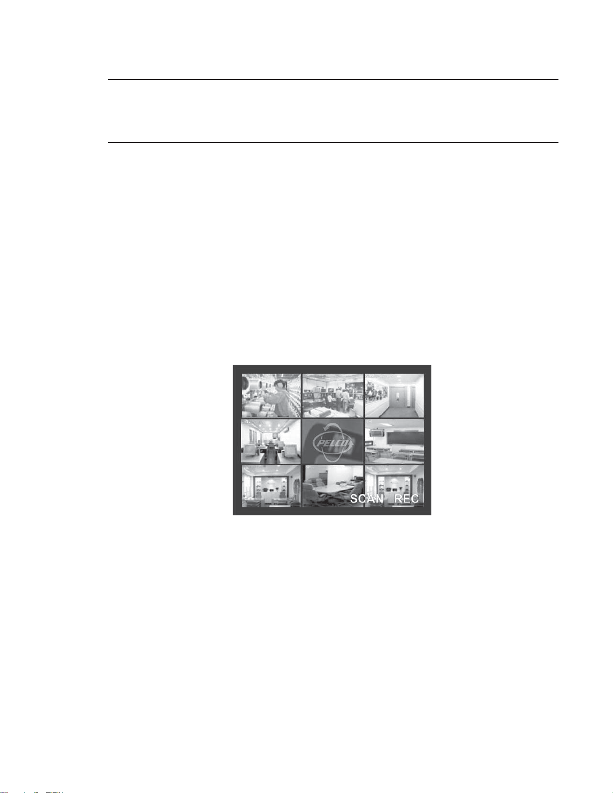
The word “SCAN” appears on the monitor during power-up at about the same time that “REC” appears (refer to Figure 6). During the scan,
the user cannot enter either SETUP or PLAYBACK modes. Only LIVE VIEW and PTZ modes are available. As soon as the unit finishes the
scan, normal operation can resume.
Figure 6. Scan Mode Engaged
If you try to access either the SETUP or PLAYBACK modes, the DX3100 displays the following message:
“WAIT UNTIL FILE SCAN IS COMPLETED”
C695M-B (11/03) 11
Page 12

OPERATING AND PROGRAMMING CONTROLS
The DX3100 can be operated and programmed either from the front panel of the unit or from the IR (infrared) remote controller.
NOTE: Each DX3100 has its own identification number or ID. This ID can be changed on the RECORDER SETUP screen on the unit. If you
change the ID on the DX3100, you must enter the new ID on the IR remote controller (refer to DX3100-IR Remote Synchronization for more
information).
Many controls on both the front panel and the IR remote controller share functions. The function of these buttons depends on the mode
(LIVE VIEW, SETUP, PLAYBACK, or PTZ). For example, the arrow buttons on the front panel and the IR remote controller are used differently
in LIVE VIEW, SETUP and PTZ modes.
Refer to the controls for each mode on the following pages. Front panel controls appear on page 13; IR remote controller controls appear
on page 14.
12 C695M-B (11/03)
Page 13
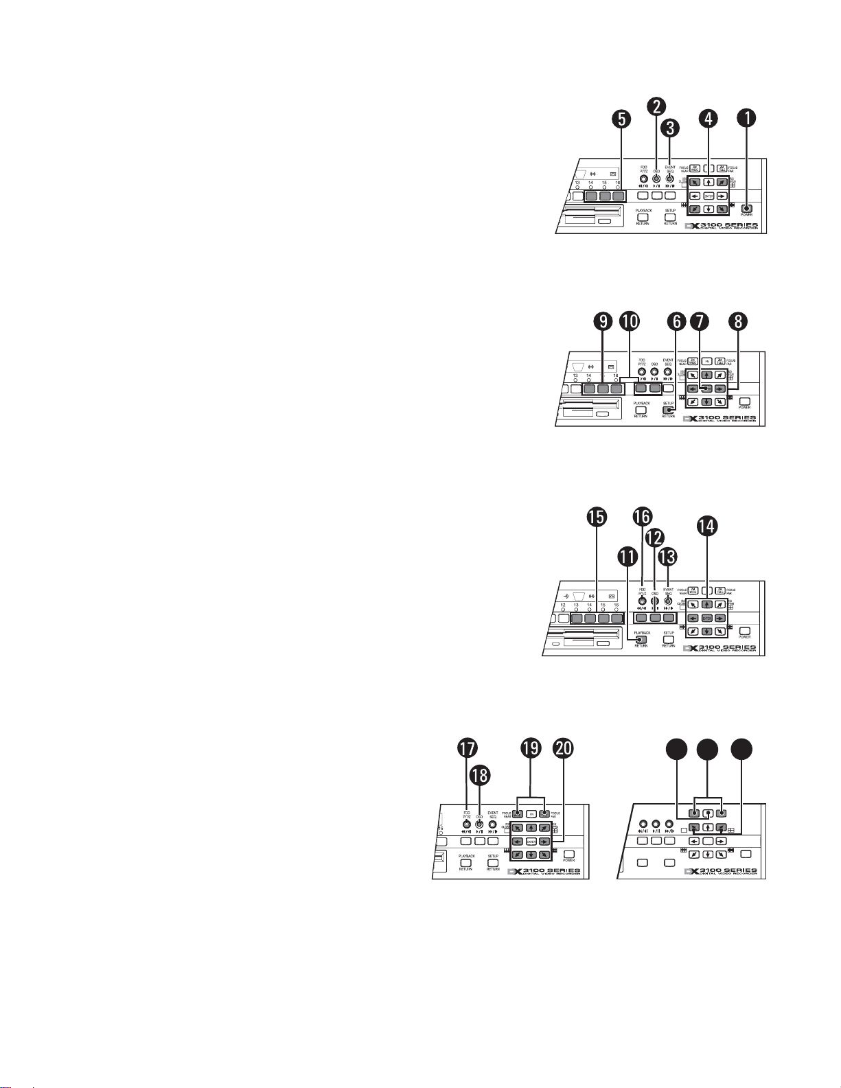
DX3100 FRONT PANEL CONTROLS
General
Power switch (startup and shutdown)
Toggle on-screen display (OSD)
Sequence
Activate multi-screen views: for 1x1, for 2x2, for 3x3, for 4x4
Display selected channel (1-8 or 1-16)
Setup
Enter and exit setup mode; exit submenus
NOTE: The default password is 1981.
Select submenu or edit field
Field selection and edit: , , ,
Edit password (DX3116): buttons 1-9 = numbers 1-9, button 10 = 0
Edit password (DX3108): buttons 1-8 = numbers 1-8,
button = number 9, button= number 0
Playback
Enter and exit playback mode
VCR-style controls for video playback
Display event list
Field selection/edit: , , , , ENTER
Display video from selected channel (1-8 or 1-16)
Save image to floppy disk
PTZ
Enter and exit PTZ mode
Toggle on-screen display (OSD)
Zoom control: ZM WIDE, ZM TELE
PTZ directional movement: , , , , , , ,
Enter and exit focus and iris controls
Focus controls: FOCUS NEAR, FOCUS FAR
Iris controls: IRIS CLOSE, IRIS OPEN
23
22
21
ZM
EVENT
FDD
FOCUS
NEAR
OSD
SEQ
P/T/Z
16
PLAYBACK
RETURN
SETUP
RETURN
IRIS
CLOSE
FN
WIDEZMTELE
ENTER
FOCUS
FAR
IRIS
OPEN
POWER
C695M-B (11/03) 13
Page 14
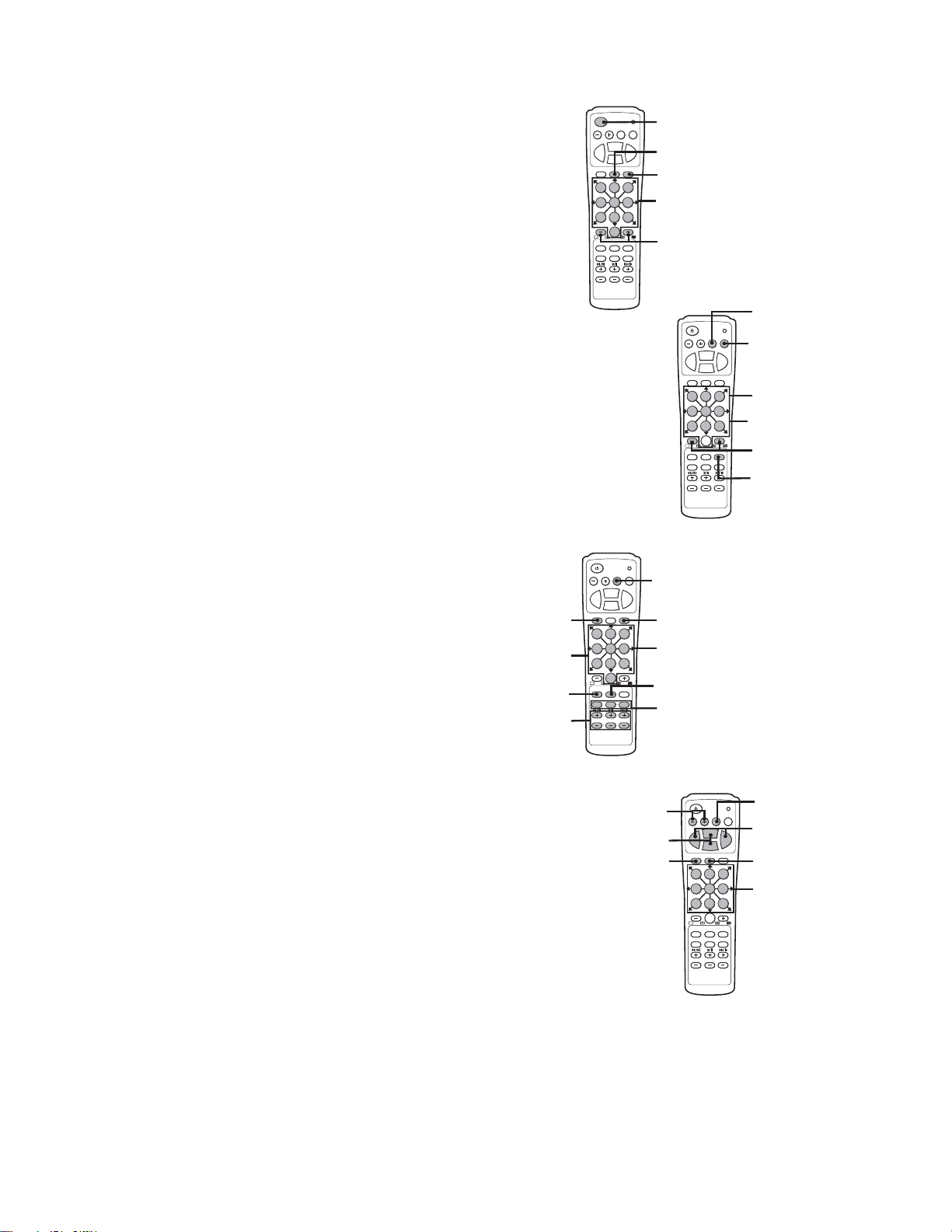
IR REMOTE CONTROLLER CONTROLS
General
Power switch (startup and shutdown)
Toggle on-screen display (OSD)
Sequence
Display selected channel full screen
Step through multi-screen views: 1x1, 2x2, 3x3, 4x4
Setup
Enter and exit setup mode; exit submenus
NOTE: The default password is 1981.
Exit submenus and setup mode
Select submenu or edit field
Field selection and edit: , , ,
Enter password
Synchronize IR remote controller to DX3100
RETURN ENTERIRIS
ZOOMIN
FOCUS
NEAR
ZOOMOUT
P/T/Z OSD SEQ
0
PLAYBACK EVENT SETUP
DAY
HOUR MIN
PELCO DX3100
IR-REMOTE
FAR
FOCUS
321
654
987
RETURN ENTERIRIS
ZOOMIN
FOCUS
NEAR
FAR
FOCUS
ZOOMOUT
P/T/Z OSD SEQ
1 3
2
5
6
4
7 9
PLAYBACK EVENT SETUP
DAY
PELCO DX3100
IR-REMOTE
8
0
HOUR MIN
Playback
Enter and exit playback mode
Exit playback mode
VCR-style controls for video playback
Display event list
Field selection/edit: , , , , ENTER
Display video from selected channel (1-8 or 1-16)
Save image to floppy disk
Increase or decrease DAY, HOUR, MINUTE fields
PTZ
Enter and exit PTZ mode
Exit PTZ mode
Toggle on-screen display (OSD)
Zoom control: ZOOM IN, ZOOM OUT
PTZ directional movement: , , , , , , ,
Focus controls: FOCUS NEAR, FOCUS FAR
Iris controls: IRIS CLOSE, IRIS OPEN
RETURN ENTERIRIS
ZOOMIN
FOCUS
NEAR
ZOOMOUT
P/T/Z OSD SEQ
4 5 6
7 8 9
0
PLAYBACK EVENT SETUP
DAY
HOUR MIN
PELCO DX3100
IR-REMOTE
FAR
FOCUS
321
FOCUS
NEAR
ZOOMOUT
P/T/Z OSD SEQ
1 2 3
7 89
PLAYBACK EVENT SETUP
DAY
PELCO DX3100
IR-REMOTE
RETURN ENTERIRIS
ZOOMIN
0
HOUR MIN
FAR
FOCUS
654
14 C695M-B (11/03)
Page 15
PROGRAMMING
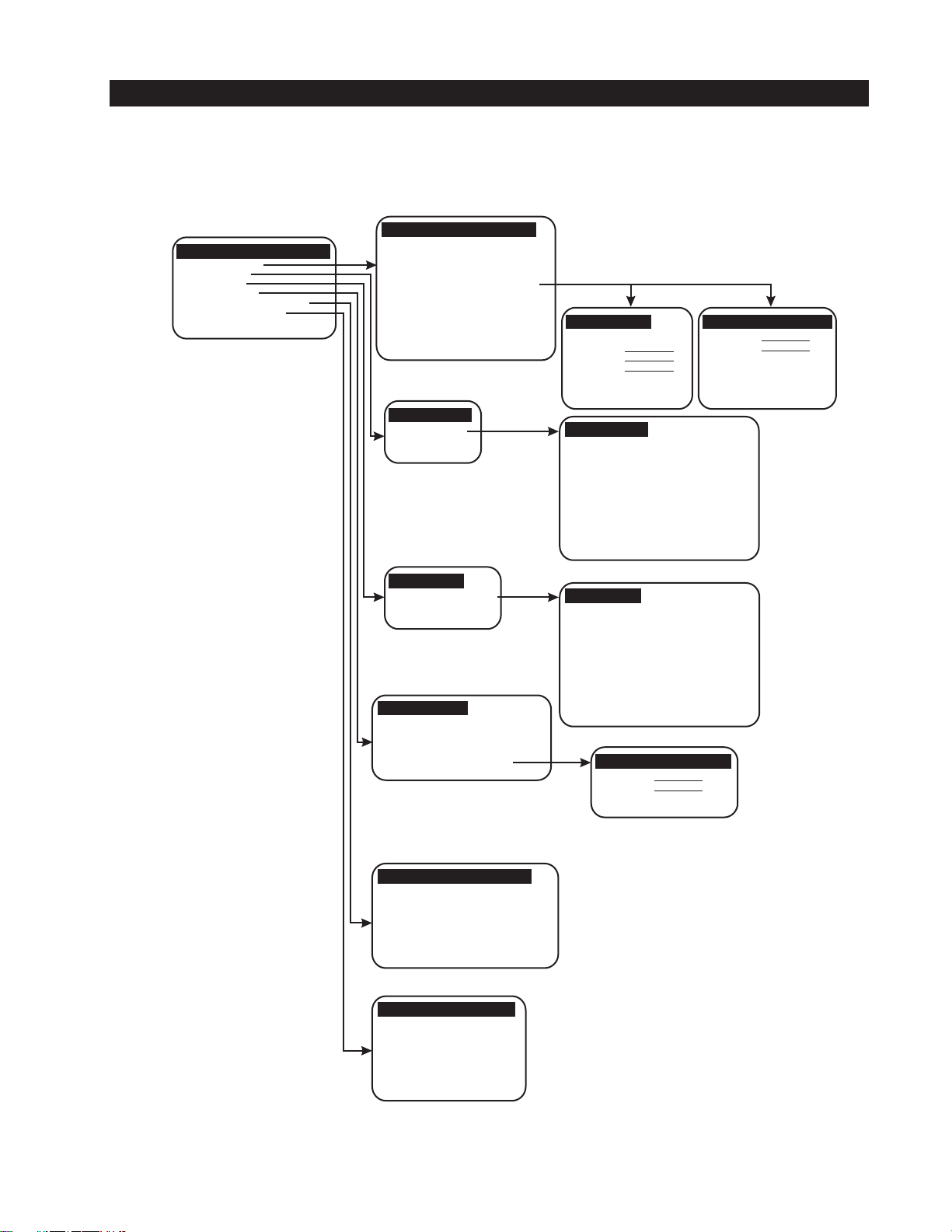
MENU STRUCTURE
All programming operations are performed in SETUP mode. Use either the DX3100 front panel buttons or the IR remote controller to
program the unit. The programming menu tree is shown in Figure 7.
PELCO DX3100 RECORDER
RECORDER SETUP
CAMERA SETUP
ALARM SETUP
NETWORK SETUP
SYSTEM STATUS & UPGRADE
ENG/DEU/ESP/FRA/POR
RECORDER SETUP
IMAGE SIZE
IMAGE RATE
PAGE SEQUENCE
DWELL
PASSWORD
TIME/DATE SET
TIME FORMAT
DAYLIGHT SAVING
IR-REMOTE ID
PTZ PROTOCOL
[352X240][640X240]
16 ips (1-30)
[ON][OFF]
5 sec (1-60)
[EDIT][CREATE]
SAT, 04/22/2002
AM 10:00:00
AM/PM OR 24HR
US
01 (00-99)
PELCO "P" or "D"
OR NONE
EDIT PASSWORD
STATUS
OLD
NEW
CONFIRM
[ADMIN][USER]
[SAVE]
CREATE USER PASSWORD
NEW
CONFIRM
[SAVE]
CAMERA SETUP
[CH1] TO [CH16]
ALARM SETUP
[ALARM 1] TO [ALARM 4]
NETWORK SETUP
CONNECTION:
IP ADDRESS:
SUBNET MASK:
GATEWAY:
PASSWORD:
[LAN]
192.168.000.002
255.255.255.000
192.168.000.001
[EDIT]
CAMERA SETUP
CAMERA NAME:
RECORD:
RECORD PARAMETER:
RECORD TIME (24 HR):
IMAGE QUALITY:
MOTION SENSITIVITY:
PTZ RX ADDRESS:
BRIGHTNESS:
CONTRAST:
HUE:
CHROMA-U:
CHROMA-V:
ALARM SETUP
ALARM ACTIVE (24 HR):
ALARMED CAMERA:
ALARM CONTACT TYPE:
RECORD MODE:
RECORD TIME:
ALARM RELAY OUT 1:
ALARM RELAY OUT 2:
EDIT NETWORK PASSWORD
NEW
CONFIRM
[SAVE]
CH1
[ON][OFF]
DEFAULT/MANUAL
00 TO 24
70 (100= Best)
100
(100= Most)
00
50
50
50
50
50
00 TO 24
1
[NO][NC]
[SET][DURATION]
5 sec (1-99)
[ON][OFF]
[ON][OFF]
SYSTEM STATUS & UPGRADE
SIGNAL SYSTEM:
HDD SPACE USED:
SOFTWARE VERSION:
HARDWARE VERSION:
IP ADDRESS:
MAC ADDRESS:
SOFTWARE UPGRADE:
NTSC
10.0 / 60.0 GB
V1.1.0
V1.1
192.168.000.002
00:06:38:00:00:02
[FDD] [LAN]
ENG / DEU / ESP / FRA / POR
LANGUAGE: ENGLISH
[LOAD NEW]
Figure 7. Menu Tree
C695M-B (11/03) 15
Page 16
SETUP MENU NAVIGATION
The DX3100 has four operating modes: LIVE VIEW, SETUP, PLAYBACK, and PTZ. LIVE VIEW, which is the default mode upon power-up, is
“home base” for the other three modes.
NOTE: When programming the DX3100, use either the DX3100 front panel controls or the IR remote controller.
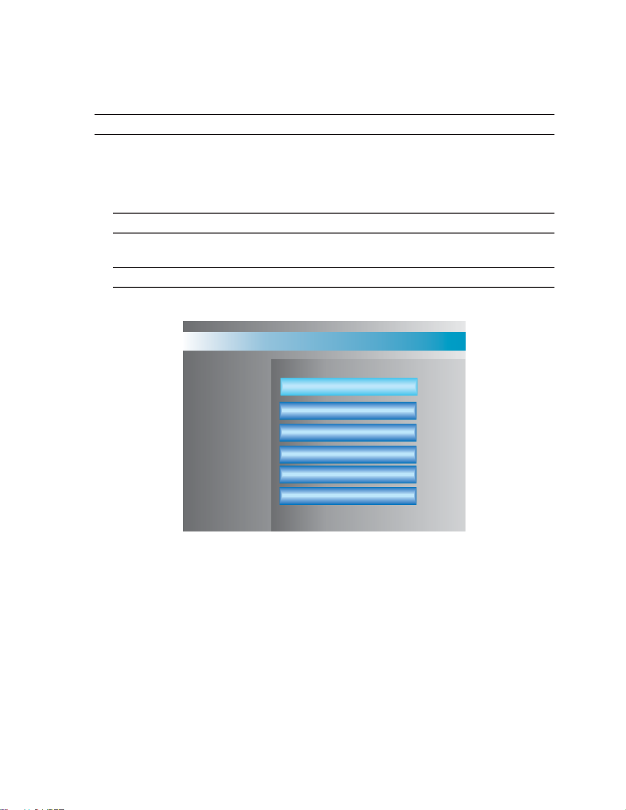
To access the DX3100 setup menu:
1. Make sure the unit is in LIVE VIEW mode. If not, exit the current mode.
2. Press the SETUP button. The unit asks for the security password.
NOTE: The default password is 1981. To implement unit security, change the password on the RECORDER SETUP screen.
3. Use the channel buttons to enter the four-digit password. The setup menu screen appears (refer to Figure 8).
NOTE: On the DX3116 front panel, use the 10 button for 0. On the DX3108 front panel, use the button for 9 and thebutton for 0.
PELCO DX3100 DIGITAL VIDEO RECORDER
RECORDER SETUP
CAMERA SETUP
ALARM SETUP
NETWORK SETUP
SYSTEM STATUS & UPGRADE
ENG / DEU / ESP / FRA / POR
Figure 8. Setup Menu Screen
To access a specific setup screen:
1. Use the up and down arrow buttons to highlight the setup option.
2. Press the ENTER button. The setup screen appears.
3. Press the SETUP button to exit the specific setup screen.
To close the DX3100 setup menu screen, press the SETUP button. The unit returns to LIVE VIEW mode.
16 C695M-B (11/03)
Page 17

Navigating specific setup menu screens is actually quite simple. The following five steps describe how to navigate the CAMERA SETUP
menu shown in Figure 9.
1. CH1 is selected. The information in the right window applies to CH1. To select a different channel, use the up and down arrow
buttons.
2. Press the ENTER button to access the CH1 setting fields. The currently selected field has a darker background. Use the up and down
arrow buttons to select a different field.
NOTE: On the IR remote controller, press the 5 button for ENTER.
3. Press the ENTER button to edit the field. The white cursor line indicates the current cursor position. Use the up and down arrow
buttons to scroll through any field options. Use the right and left arrow buttons to move either to the next position in the field or to
the next field. To exit the field, press the SETUP button.
4. On-screen buttons provide access to additional settings. Use on-screen buttons to gain access to additional settings, in this case
RECORD PARAMETERS for CH1. Use the up and down arrow buttons to select one of these additional fields.
In this example, when DEFAULT is selected, the RECORD PARAMETERS for CH1 can be neither accessed nor changed. They are
grayed out or disabled. When MANUAL is selected, these additional settings can be both accessed and changed. If DEFAULT is
selected again, the RECORD PARAMETERS are reset to their default values and then disabled.
5. Many setup screens offer additional information, which appears in black lettering.
To go from here to here, press
the ENTER button.
:
To go from here to here, press
the SETUP button.
To return to
LIVE VIEW,
press the
SETUP
button.
To return to the
MAIN MENU,
press the SETUP
button.
To go from here to here, press
the ENTER button.
To go from here to here, press
the SETUP button.
Figure 9. Navigating the CAMERA SETUP Screen
Some on-screen buttons allow access to additional screens. Highlight the button and press the ENTER button. Change the appropriate
settings and then press the SETUP button to exit that screen.
C695M-B (11/03) 17
Page 18

DX3100-IR REMOTE SYNCHRONIZATION
If your IR remote controller does not work with a specific DX3100, perform the following:
1. Obtain the IR remote identification number for the DX3100 from your administrator, or, if you can access SETUP mode on the DX3100,
open the RECORDER SETUP screen and note the IR REMOTE ID (refer to Figure 12). It will be a number between 00 and 99.
2. Press the - and + buttons on the IR remote controller simultaneously. These buttons are located on the left and right side of the 0
button (refer to Figure 10).
3. The red LED on the unit should light.
4. Use the number keys on the remote to immediately enter the IR REMOTE ID for the DX3100. If the remote accepts the number, the
red LED will flash on and off a couple of times.
The IR remote controller should now be able to control the DX3100.
Figure 10. DX3100-IR Remote Synchronization
18 C695M-B (11/03)
Page 19

STORAGE CALCULATIONS
Due to the nature of digital video recording, the particular capabilities of the DX3100, and the different parameters for each installation, it
is very difficult to calculate storage capacity. Desired image size, record rate, image quality, and number of channels are only a few of the
variables that affect capacity.
Before configuring the DX3100, work through this section to identify the desired settings for the DX3100 as well as all channels that are
connected to it. This section describes how different settings impact storage capacity.
NOTE: Values indicating video storage capacity are estimates only. These estimates are to be used as guidelines in determining proper
hard drive requirements. Many user-selectable factors, including image quality, recording rate, image content/motion, and video noise,
affect the total unit storage capacity. These estimates will vary based on actual use. These estimates are not an implied or expressed
guarantee of actual performance.
C695M-B (11/03) 19
Page 20

Average Image Size in KB (IMAGE SIZE)
File size affects how long you can record for a given time period. The greater the file size, the
faster you will use available hard disk space. The resolution setting reflects the size of the
recorded display and thus the KB size per image. For 352 x 240, the average file size is 3KB to
5KB. A 640 x 240 choice results in a 4KB to 8KB average file size. These resolution settings
only affect the image size, not the image quality.
Actual image size can vary within the ranges mentioned for the given resolutions based on
the dynamic interplay of image motion and image complexity (over which you have no
control). Moreover, the IMAGE QUALITY and MOTION SENSITIVITY settings for each channel
in the CAMERA SETUP menu have an effect. For example, if MOTION SENSITIVITY is set to
100 for a channel, it will record all of the time.
Images per Second (IMAGE RATE)
Enter the total images per second (ips) to be shared by all channels on the DX3100. The
unit can record 1 to 30 ips for NTSC or 1 to 25 ips for PAL. Enter the highest ips rate
required for your installation. Keep in mind that the higher the IMAGE RATE, the lower
the storage capacity. However, at lower IMAGE RATEs, the unit records fewer images
per channel.
For example, on a DX3116 with 16 channels that is set to 30 ips (NTSC), the unit
records 1.875 ips for each channel (30 ips / 16 channels). If there are only 12 channels
at 30 ips, the unit records 2.5 ips for each channel. If you have 15 channels at 15 ips,
the unit only records one ips for each channel.
Recording Hours per Day (RECORD TIME)
Enter the minimum number of recording hours for the installation. For example, if
the unit only records from 7:00 p.m. to 7:00 a.m., this number is 12. This is a
global setting and applies equally to all channels that have recording enabled.
Number of Days to Store
Enter the number of days per month that the system will be used. There is
no menu setting for this item.
0.0036 (Multiplier)
This fixed value represents the amount of required storage capacity,
in gigabytes, to record one KB per second for one hour.
CH 1
CH 9
CH 2
CH 10
CH 3
CH 11
CH 4
CH 12
CH 5
CH 13
CH 1
CH 9
CH 2
CH 10
CH 3
CH 11
CH 4
CH 12
CH 5
CH 13
CH 1
CH 9
CH 2
CH 10
CH 3
CH 11
CH 4
CH 12
CH 5
CH 13
Average Image Size (KB) x Images per Second (ips) x
Recording Hours per Day (hrs.) x Number of Days to
[]
Store x 0.0036 (Multiplier)
Average Images per Recording Number of 0.0036 Needed
Image Size Second (ips) Hours per Days to (Multiplier) Capacity
(KB) Day (hrs.) Store (GB)
Examples:
31512300.0036 58.32
33012300.0036 116.64
51524300.0036 194.40
33024300.0036 233.28
NOTE: The DX3108-240 and the DX3116-240 each have a maximum capacity of 240GB.
= Needed Capacity (GB)
20 C695M-B (11/03)
Page 21

DX3100 CONFIGURATION
The DX3100 setup menu screen is shown in Figure 11.
PELCO DX3100 DIGITAL VIDEO RECORDER
RECORDER SETUP
CAMERA SETUP
ALARM SETUP
NETWORK SETUP
SYSTEM STATUS & UPGRADE
ENG / DEU / ESP / FRA / POR
Figure 11. Setup Menu Screen
The DX3100 setup menu screen offers access to the following setup screens:
RECORDER SETUP Update the unit parameters. These include image size, image rate, password management, time and
date, PTZ protocol, and IR remote ID.
CAMERA SETUP Update the title and recording parameters for each channel input.
ALARM SETUP Update the parameters for each alarm input and output.
NETWORK SETUP Update the network address settings: IP, subnet, and gateway.
SYSTEM STATUS & UPGRADE Display general system information. Also upgrade unit software from the floppy disk drive or a network
connection.
ENG/DEU/ESP/FRA/POR Select the unit language.
NOTE: The DX3100 only supports English at present.
C695M-B (11/03) 21
Page 22

RECORDER SETUP
Highlight the RECORDER SETUP option on the setup menu screen and press the ENTER button. The RECORDER SETUP screen appears
(refer to Figure 12).
RECORDER SETUP
:
IMAGE SIZE
IMAGE RATE
PAG E SEQUENCE
DWELL
PASSWORD
TIME / DATE SET
TIME FORMAT
DAYLIGHT SAVING
IR-REMOTE ID
PTZ PROTOCOL
Figure 12. Recorder Setup Screen
352X240
16
:
:
ON
:
3
:
EDIT
:
WED,04/24/2002
AM 10:42:34
:
AM/PM
:
US
:
01
:
PELCO “P”
ips
OFF
sec (1-60)
CREATE
(00-99)
IMAGE SIZE Select the pixel resolution for each recorded image. Choose either 352 x 240 or 640 x 240. The larger size offers
higher image quality, but uses twice as much storage capacity as the smaller size. This global setting applies to all
channels. The default is 352 x 240.
IMAGE RATE Select the total per-second image rate for the unit. This rate is shared equally among available channels. Select a
number between 1 and 30 (NTSC) or 1 and 25 (PAL). For example, if the rate is 30 ips with 16 channels, the image
rate for each channel is 1.875 ips (30 / 16 = 1.875). The default setting is 8 ips for DX3108 models and 16 ips for
DX3116 models. For the relationship between image rate and alarmed channels, refer to
Record Mode
under
Alarm
Setup.
PAGE SEQUENCE Select ON to enable page sequencing. Select OFF to disable page sequencing. The default is ON.
DWELL If page sequencing is enabled, set the number of seconds to display each channel before proceeding to the next
channel in the sequence. Select the number of seconds from 1 to 60. The default is 3.
PASSWORD Create or update the ADMIN and USER passwords. The default ADMIN password is 1981. The default USER
password is blank.
When preparing system security, you have three options:
• Keep the default ADMIN password.
• Change the default ADMIN password and set up password security.
• Remove the ADMIN password to disable password security.
To access the PTZ and PLAYBACK modes, enter the USER password. To access SETUP mode or to shut down the unit,
enter the ADMIN password. LIVE VIEW mode does not require a password.
NOTE: When entering a password on the DX3116, press the 10 button to enter 0. On the DX3108, press the
button to enter 9 and the button to enter 0.
22 C695M-B (11/03)
Page 23

Edit Password Select EDIT and press the ENTER button. The EDIT PASSWORD screen appears.
STATUS: Select the password to change: ADMIN or USER.
OLD (ADMIN only): Enter the current four-digit password by pressing the numbered channel
buttons. An asterisk is displayed as each number is entered to maintain security.
NEW: Enter the new four-digit password by pressing the numbered channel buttons. An
asterisk is displayed as each number is entered to maintain security.
CONFIRM: Reenter the new four-digit password by pressing the numbered channel buttons.
An asterisk is displayed as each number is entered to maintain security.
SAVE: Select SAVE and press the ENTER button to save the new password.
Exit: Press the SETUP button to exit the EDIT PASSWORD screen.
NOTE: To delete a password, leave the NEW and CONFIRM fields blank. Then save the blank password.
Create Password To create the USER password, select CREATE and press the ENTER button. The CREATE
USER PASSWORD screen appears.
NEW: Enter the new four-digit password by pressing the numbered channel buttons. An
asterisk is displayed as each number is entered to maintain security.
CONFIRM: Reenter the new four-digit password by pressing the numbered channel buttons.
An asterisk is displayed as each number is entered to maintain security.
SAVE: Select SAVE and press the ENTER button to save the new password.
Exit: Press the SETUP button to exit the EDIT PASSWORD screen.
NOTE: To delete a password, leave the NEW and CONFIRM fields blank. Then save the blank password.
TIME/DATE SET Enter the current time and date. Select and scroll through the day, date, and time fields, incrementing or
decrementing each entry until all are correct.
NOTE: Be sure to enter the correct time and date. Unit operations, including searches, involve time-based
parameters that are referenced against this setting.
Since all recording in progress is paused temporarily until setup mode is exited, it is recommended that you exit
setup immediately after you set the time and date.
TIME FORMAT Select AM/PM or 24HR.
C695M-B (11/03) 23
Page 24

DAYLIGHT SAVING Select the country to set daylight saving time (DST).
If you select a European country, the date format changes to DD/MM/YYYY. For all other countries, the date format
is MM/DD/YYYY. The default is US.
NOTE: After changing the daylight saving setting, the unit temporarily pauses all recording until SETUP mode is
exited. Therefore, you should exit SETUP mode as soon as possible.
When you exit SETUP MODE after changing DAYLIGHT SAVING, the DX3100 performs a file scan process of all
recorded files. This procedure may take several minutes, during which time you cannot enter SETUP or PLAYBACK
mode. The word “SCAN” appears on the monitor display.
IR REMOTE ID Select the IR remote controller identification code (00-99). Any IR remote controller that is set to this number can
access this DX3100. The default is 01.
PTZ PROTOCOL Select the Pelco protocol for controlling PTZ receivers that are connected to the unit. Choose between PELCO D,
PELCO P and NONE. The default is NONE.
Since this is a global setting, all receivers attached to this unit must be configured for the same protocol.
NOTE: Baud rates for Pelco P and Pelco D protocols are fixed at 4800 and 2400 respectively. Therefore, receiver
protocol baud rate settings should correspond.
24 C695M-B (11/03)
Page 25

CAMERA SETUP
Highlight the CAMERA SETUP option on the setup menu screen and press the ENTER button. The CAMERA SETUP screen is shown in
Figure 13.
CAMERA SETUP
:
CH 1
CH 2
CH 3
CH 4
CH 5
CH 6
CH 7
CH 8
CAMERA NAME
CH 9
CH 10
CH 11
CH 12
CH 13
CH 14
CH 15
CH 16
RECORD (24 HR)
RECORD PARAMETER
RECORD TIME (24 HR)
IMAGE QUALITY
MOTION SENSITIVTY
PTZ RX ADDRESS
BRIGHTNESS
CONTRAST
HUE
:
:
:
Figure 13. Camera Setup Screen
50
50
50
CH1
:
ON
:
DEFAULT MANUAL
:
0
:
100=Best
70
:
100
(00-99)
0
:
CHROMA-U:
CHROMA-V:
24
to
50
50
CAMERA NAME Label the channel with an alphanumeric name (up to 15 characters). The channel name and other information
appear on the monitor when the channel is selected.
NOTE: When sequencing in LIVE VIEW mode, the on-screen display (OSD) is not redisplayed until the unit
sequences again.
Press the OSD button to toggle the channel name on and off. The OSD button is active in LIVE VIEW and PTZ
modes and also when sequencing in LIVE VIEW mode (refer to the
Operation
section in this manual).
NOTE: When the 3x3 screen format is selected, the DX3100 only displays the first 11 characters of each channel
name. When the 4x4 screen format is selected, the DX3116 only displays the first seven characters of each channel
name.
RECORD Enable or disable recording for each individual channel. Select and choose between ON or OFF. Channels with
record off are not included in calculations for total shared image rate of recorded channels. For each channel that is
set to record OFF, there is a related increase in the individual image rate for channels with record ON.
RECORD
PARAMETERS Determine the recording parameters. Select either DEFAULT or MANUAL. If DEFAULT is chosen, all record
parameters will be set to default values. If MANUAL set is chosen, all record parameters can be adjusted.
RECORD TIME Specify the time span for recording this channel if record ON is selected (refer to
Record
above). This setting indicates the recording start and stop time for each day. The time format
is always 24-hour and the default is 0 to 24, that is, midnight to midnight.
IMAGE QUALITY Specify the general image quality in increments of 10 on a scale of 0 (minimum) to 100
(maximum). The default is 70.
This setting affects the size of each recorded image. Higher settings result in larger image
sizes and reduced recording capacity. Lower settings result in smaller image sizes and
increased recording capacity. Select a quality that meets the needs of your installation.
C695M-B (11/03) 25
Page 26

MOTION
SENSITIVITY Specify the level of motion that is required to record captured images. This level is in
increments of 10 on a scale of 0 (minimum) to 100 (maximum). The default is 100.
At maximum sensitivity (100), motion detection is actually not used. The unit records all
images from the channel; it does not skip any images.
The DX3100 evaluates each image to identify the amount of change from the previous image.
If the amount of change is above the threshold, the unit records the image. If the amount of
change is below the threshold, the unit skips the image.
PTZ RX ADDRESS Specify the PTZ RX address that is configured for this camera. The default is 00, which means
none specified.
BRIGHTNESS Specify the brightness level for this channel. This setting ranges from 0 (minimum) to 100
(maximum). The default is 50.
CONTRAST Specify the contrast level for this channel. This setting ranges from 0 (minimum) to 100
(maximum). The default is 50.
HUE Specify the hue level for this channel. This setting ranges from 0 (minimum) to 100
(maximum). The default is 50.
CHROMA-U
CHROMA-V Specify the color levels for this channel. These settings range from 0 (minimum) to 100
(maximum). The default is 50.
26 C695M-B (11/03)
Page 27

ALARM SETUP
Highlight the ALARM SETUP option on the setup menu screen and press the ENTER button. The ALARM SETUP screen is shown in
Figure 14.
ALARM SETUP
ALARM 1
ALARM 2
ALARM 3
ALARM 4
ALARM ACTIVE (24 HR)
ALARMED CAMERA
ALARM CONTACT TYPE
RECORD MODE
RECORD TIME
ALARM RELAY OUT 1
ALARM RELAY OUT 2
:
0
:
1
:
N/O
SET
:
:
5
:
OFF
:
OFF
to
24
DURATION
sec (1-99)
Figure 14. Alarm Setup Screen
NOTE: These settings only apply to how the DX3100 records alarmed channels.
ALARM ACTIVE Select the start and stop time for this alarm. This setting indicates the activation start and stop time for each day.
The time format is always 24-hour and the default is 0 to 24, that is, midnight to midnight.
ALARM
CONTACT TYPE Select the type of contact that is connected to the alarm input terminal: N/O (normally open) or N/C (normally
closed). The default is N/O.
RECORD MODE Set the recording behavior when this alarm is activated. The default is SET.
SET When the alarm is triggered, the unit records the alarmed channel at the full frame rate for
the number of seconds specified in the RECORD TIME field. The unit ignores any alarm
deactivation.
DURATION When the alarm is triggered, the unit records the alarmed channel at the full frame rate until
the alarm is deactivated.
Channels that are programmed for alarm recording have precedence over channels that are
not alarmed. When an alarm is triggered, the alarmed channel records at the per-image rate
entered in the RECORDER SETUP menu. If the ips setting is relatively high, the recorded
image rate of the alarmed channel approaches real-time viewing quality. If more than one
alarmed channel is triggered, the ips rate is shared equally among the alarmed channels. All
nonalarmed channel recording is halted for the duration of the alarm.
RECORD TIME SET only: Set the alarm record time for alarm activation. This setting ranges from 1 to 99 seconds. The default is
5 seconds.
ALARM RELAY
OUT 1 Select ON to enable the first alarm relay output. If the alarm is activated, the unit closes alarm relay output 1 for
the duration of alarm activation. Select OFF to disable this relay output.
ALARM RELAY
OUT 2 Select ON to enable the second alarm relay output. If the alarm is activated, the unit closes alarm relay output 2 for
the duration of alarm activation. Select OFF to disable this relay output.
C695M-B (11/03) 27
Page 28

NETWORK SETUP
Highlight the NETWORK SETUP option on the setup menu screen and press the ENTER button. The NETWORK SETUP screen is shown
in Figure 15.
NETWORK SETUP
:
CONNECTION
IP ADDRESS
SUBNET MASK
GATEWAY
PASSWORD
LAN
:
192.168.000.001
255.255.255.000
:
192.168.000.001
:
EDIT
:
EDIT NETWORK SETUP
NEW
CONFIRM
:
:
SAVE
Figure 15. Network Setup Screen
NOTE: Only set up the following network parameters if you will access this unit over a network.
CONNECTION For each of the following three fields, you must enter a valid network address. Each of the four IP address fields are
separated by decimal points and have three digits that range from 000 to 255.
IP ADDRESS Enter the IP address for the DX3100 on the TCP/IP network. Obtain a valid IP address from your network
administrator. The default is 192.168.000.xxx, where xxx is the decimal equivalent of the hexadecimal value of the
last byte of the network card address.
SUBNET MASK Enter the subnet mask for the DX3100 on the TCP/IP network. Obtain the subnet mask from your network
administrator. The default is 255.255.000.000.
GATEWAY Enter the address for the network gateway or router. Obtain the gateway address from your network administrator.
This address is required for connecting to the unit remotely from outside of the network router. The default is
192.168.000.001.
EDIT NETWORK
PASSWORD Connecting to the unit from a remote workstation requires a password. The default is 1981. To edit this password,
select EDIT and then press the ENTER button.
NEW Enter a new four-digit password from the front panel or IR remote controller.
CONFIRM Confirm the new password by entering it again from the front panel or IR remote controller.
SAVE Save the new password.
Enter this password in the connection property sheet in the DX3100RX software (refer to
in the
DX3100 Series Remote Site Software
28 C695M-B (11/03)
manual).
Connecting to the DX3100
Page 29

SYSTEM STATUS AND UPGRADE
Highlight the SYSTEM STATUS & UPGRADE option on the setup menu screen and press the ENTER button. The SYSTEM STATUS &
UPGRADE screen is shown in Figure 16. It provides access to important system details.
SYSTEM STATUS & UPGRADE
:
SIGNAL SYSTEM
HDD SPACE USED
SOFTWARE VERSION
HARDWARE VERSION
IP ADDRESS
MAC ADDRESS
SOFTWARE UPGRADE
Figure 16. System Status Screen
NTSC
:
10.0 / 60.0 GB
:
V1.1.0
V1.1
:
:
192.168.000.002
:
00:06:38:00:00:02
FDD
:
LAN
SIGNAL SYSTEM Displays the setting of the NTSC/PAL switch on the rear of the unit.
HDD SPACE USED Displays the used storage space and the total available storage space.
SOFTWARE
VERSION Displays the version of the currently installed software.
HARDWARE
VERSION Displays the current hardware version.
IP ADDRESS Displays the IP address for the unit that was entered on the NETWORK SETUP screen.
MAC ADDRESS Displays the unique MAC (Media Access Control) address for the network interface card for the DX3100. The MAC
address consists of six bytes of hexadecimal values.
SOFTWARE
UPGRADE Use this option to upgrade the DX3100 system software, either from a set of floppy diskettes or from a network
drive. Refer to the
Software Upgrade
section in the
DX3100 Series Remote Site Software
manual for complete
information.
C695M-B (11/03) 29
Page 30

ENG/ DEU/ ESP/ FRA/ POR (LANGUAGE)
Highlight the ENG/ DEU/ ESP/ FRA/POR option on the setup menu screen and press the ENTER button. The language setup screen is
shown in Figure 17.
NOTE: The DX3100 only supports English at present.
ENG / DEU / ESP / FRA / POR
LANGUAGE: ENGLISH
LOAD NEW
Figure 17. Language Setup Screen
LANGUAGE Displays the language that has been set for the DX3100.
LOAD NEW Select this option to change the system language.
30 C695M-B (11/03)
Page 31

OPERATION
The DX3100 offers three operating modes: LIVE VIEW, PLAYBACK, and PTZ.
LIVE VIEW mode displays live video from one or more channels (refer to
PLAYBACK mode lets you select and then view recorded video (refer to
PTZ mode lets you control PTZ-capable cameras (refer to
SETUP mode lets you configure the DX3100 (refer to
PTZ Mode
Programming
for more information).
for more information).
Live View Mode
Playback Mode
for more information).
for more information).
C695M-B (11/03) 31
Page 32

LIVE VIEW MODE
When first powered up, the DX3100 opens in LIVE VIEW mode. Figure 18 shows sample LIVE VIEW screens for the DX3108 (3x3 format)
and the DX3116 (4x4 format).
CH1
CH4
CH6
CH2
CH7
CH3
CH5
CH8
CH7
DX3108 DX3116
Figure 18. DX3100 Sample LIVE VIEW Screens
Video from all active inputs is displayed on the monitor. The channel LED on the front panel also lights for each active input.
In LIVE VIEW mode, you can
• Display the on-screen overlay
•View live video from one or many active inputs
• Define and run channel display sequences
NOTE: When video is being recorded, “REC” appears at the bottom right of the screen. Its appearance is independent of the current
screen format or view. For example, if input 10 is recording and input 12 is displayed, “REC” still appears on the screen. Use the OSD
button to either hide or display “REC.” The OSD button does not affect recording.
32 C695M-B (11/03)
Page 33

ON-SCREEN OVERLAY
The DX3100 displays the name for each channel, unit date and time, and record status as an on-screen overlay (refer to Figure 19). Press
the OSD button to either hide or display this overlay. The OSD button does not affect recording.
NOTE: When the 3x3 screen format is selected, the DX3100 only displays the first 11 characters of each channel name. When the 4x4
screen format is selected, the DX3116 only displays the first seven characters of each channel name.
CH 1
01/14/2002 AM 11/15/23
Figure 19. On-Screen Overlay
VIEWING VIDEO
Single Screen Viewing
To view a single channel full-screen, simply press the channel button for that display. In Figure 20, selecting channel 7 switches from the
4x4 format to a single screen. Selecting channel 12 switches channels, but keeps the full-screen format.
7
7
Figure 20. Channel Selection
On the IR remote controller, enter the number of the channel to view from the numeric keypad.
NOTE: To allow selection of channels 10 to 16, there is a one-second delay after you press the 1 button.
12
C695M-B (11/03) 33
Page 34

Multiple Screen Viewing
For multiple screen viewing, the DX3100 groups channels into specific sets for each screen format: 1x1, 2x2, 3x3, and 4x4. Table C
identifies the channel sets for each screen format.
Table C. DX3100 Channel Sets
DX3116 DX3108
1x1 16 “sets” 8 “sets”
One for each channel One for each channel
2x2 Four sets Two sets
Channels 1-4 Channels 1-4
Channels 5-8 Channels 5-8
Channels 9-12
Channels 13-16
3x3 Two sets One set
Channels 1-9 Channels 1-8
Channels 8-16
4x4 One set
Channels 1-16
To view one (1x1), four (2x2), nine (3x3), or 16 (4x4) channels, press the screen format button on the front panel. The DX3100 displays the
set of channels based on the previous screen format. For example, if you select 2x2 when channel 5 is displayed full-screen, the DX3100
displays channels 5-8.
To step through screen sets, press the screen format button again. When the last set is displayed, press the screen format button again to
display the first set.
Figure 21 shows how to step through each screen set from the front panel. Each time you press the screen format button, the next set
appears.
13 14
10
9
5
6
15
8
1-4
16
13 - 16
9-12
5-8
11 12
1
16
1
12
7
4
3
89
123
11
12
4
56
15
14
78 9
10
13
16
8-16
1-9
123 4
5678
910 12
131114 1615
16
Figure 21. Stepping Through Screen Sets: Front Panel
34 C695M-B (11/03)
Page 35

When using the IR remote controller, you must step through screen sets in a linear fashion: full-screen channels followed by the 2x2, 3x3,
and 4x4 sets (refer to Figure 22). Press the + button to advance through the channel sets (1x1, 2x2, 3x3, 4x4). Press the - button to step
backward through the channel sets (4x4, 3x3, 2x2, 1x1).
13 14
10
9
5
6
15
8
1-4
16
13 - 16
9-12
5-8
11 12
12
1
16
1
7
4
3
+ AND - BUTTONS ON IR REMOTE CONTROLS MULTICHANNEL OPERATION
89
123
11
12
4
56
15
14
78 9
10
13
16
8-16
1-9
123 4
5678
910 12
131114 1615
16
Figure 22. Stepping Through Screen Sets: IR Remote Control
Sequences
You can automate the process of displaying multiple channels and channel sets. Press the SEQ button to set up the sequence; “SEQ”
appears on the top right of the screen. Select the channels and screen formats in their proper order. To stop sequencing, press the SEQ
button again.
NOTE: To use sequencing, you must enable it in the RECORDER SETUP screen. You can also set the DWELL TIME, that is, how long each
screen is displayed before the next screen in the sequence appears. Dwell time is a global item and applies equally to all sequence types.
NOTE: Sequence only displays channels with active video.
C695M-B (11/03) 35
Page 36

PLAYBACK MODE
Use PLAYBACK mode to view recorded video for a specific channel.
NOTE: In PLAYBACK mode, recorded video can only be displayed full-screen.
In PLAYBACK mode, you can
• Use several methods to locate specific segments of recorded video
• Save a particular frame or video image to a floppy diskette
• Access lists of system events, which include
• System performance information, including each time the unit was either shut down or powered up
• Recorded video grouped by alarm event and number, including the time and date of alarm events. Each alarm event can be
accessed directly for immediate playback without performing time searches (refer to
NOTE: The compression structure of MPEG video data causes observational differences when using the step-forward and step-reverse
controls. For more information, refer to
MPEG Structure and Frame Operations
Event
later in this manual.
later in this manual)
36 C695M-B (11/03)
Page 37

STARTING PLAYBACK MODE
Enter PLAYBACK mode from LIVE VIEW mode by pressing the PLAYBACK button. A sample of the opening on-screen overlay is shown in
Figure 23.
Figure 23. Opening Playback Overlay
The DX3100 always defaults to channel 1 when you first enter PLAYBACK mode. When you select a different channel, the overlay appears
for that channel.
The BEGIN and END fields on the overlay give the range of recorded video for the selected channel. The current END time does not
change until you exit PLAYBACK mode.
NOTE: The time at the bottom of the screen applies to the last video image that was displayed. It has nothing to do with the current
BEGIN-END timeline. The pause icon appears in the lower right corner.
Recorded video is not stored in one linear, contiguous track that stretches from the BEGIN to END time stamps. Instead, recorded video is
stored in time files. Each channel is assigned its own set of time files.
Time files are each limited to one hour. At the end of an hour, the unit closes the current file for the channel and starts a new file.
When you enter PLAYBACK mode, the DX3100 makes all complete time files available for searching. Open time files, that is, files with
less than one hour of video, are not available for searching. To view video from an open time file, refer to
Searching Open Time Files.
C695M-B (11/03) 37
Page 38

ACCESSING RECORDED VIDEO
When you enter PLAYBACK mode for the first time, the unit automatically advances to the end of the last complete time file for channel 1
(refer to Figure 24).
PLAYBACK
BUTTON
PRESSED
CH1
CH2
CH16
TIME
TIME FILE
TIME FILE
TIME FILE
BEGIN
1HR
1HR
1HR
1HR
TIME FILE
1HR
TIME FILE
1HR
TIME FILE
1HR
TIME FILE
1HR
TIME FILE
1HR
TIME FILE
END
RECORDING
CONTINUES
SEARCHABLE
VIDEO
Figure 24. Playback Mode Entry Time Files
To view previously recorded video for a channel, you must “rewind” to the desired time file:
1. Press the play/pause button. The play icon appears on-screen.
2. Immediately press the fast reverse button. The reverse icon appears on-screen.
3. Press the play/pause button again. The play icon appears on-screen again.
You can use the three VCR-style control buttons to view the video. Whenever you press one of these control buttons, the BEGIN-END time
overlay disappears.
When you return to PLAYBACK mode, the unit automatically returns to the time frame that was last accessed for channel 1.
38 C695M-B (11/03)
Page 39

SWITCHING CHANNELS
When you re-enter PLAYBACK mode, the unit automatically displays recorded video for channel 1. The unit automatically returns to the
timeframe that was last accessed for channel 1.
To view video from a different channel, press the button for the desired channel. The on-screen overlay appears with the BEGIN and END
fields, giving the range of recorded video for the channel.
When you switch to a different channel, the unit displays video from the same time frame for the new channel. Figure 25 shows what
happens when you switch from channel 2 to channel 7 to channel 8. The unit accesses recorded video at the same time on each channel.
CH1
CH2
CH3
CH7
CH8
1HR
TIME FILE
1HR
TIME FILE
1HR
TIME FILE
1HR
TIME FILE
1HR
TIME FILE
1HR
TIME FILE
1HR
TIME FILE
1HR
TIME FILE
1HR
TIME FILE
1HR
TIME FILE
1HR
TIME FILE
1HR
TIME FILE
1HR
TIME FILE
1HR
TIME FILE
1HR
TIME FILE
Figure 25. Play Back Different Channels
When you use any of the VCR-type controls, the BEGIN-END timeline disappears from the screen. The time frame for the channel also
moves. If you switch to a different channel, the unit displays video from the new time frame as well as the on-screen overlay with the
BEGIN and END fields.
C695M-B (11/03) 39
Page 40

SEARCHING FOR SPECIFIC VIDEO
In addition to switching to a different channel, you can switch to video at an earlier or a later point in time. Then you can switch to a
different channel, based on the new time frame.
To access a different time frame, use one of the following methods to select the desired date and time:
• DX3100 Front Panel:
1. Press the and buttons to select a field to change: month, day, year, hour, minutes.
2. Press the and buttons to increase or decrease the field value.
3. Press the ENTER button.
4. Use the VCR-type controls to playback video.
• IR Remote Controller:
1. Press the + or - button for DAY, HOUR, and MIN to select the desired date and time.
2. Press the ENTER button.
3. Use the VCR-type controls to playback video.
NOTE: There is no cursor movement when using the IR Remote Controller to select a date and time.
In Figure 26, the user switches from channel 1 to channel 2, keeping the same time frame. Then the user backs up a couple of hours.
When the user switches to channel 8, the DX3100 maintains the new time frame.
NOTE: If you select a date and time, but do not press the ENTER button, the DX3100 will ignore your date and time parameters.
CH1
CH2
CH3
CH7
CH8
1HR
TIME FILE
1HR
TIME FILE
1HR
TIME FILE
1HR
TIME FILE
1HR
TIME FILE
1HR
TIME FILE
1HR
TIME FILE
1HR
TIME FILE
1HR
TIME FILE
1HR
TIME FILE
1HR
TIME FILE
1HR
TIME FILE
1HR
TIME FILE
1HR
TIME FILE
1HR
TIME FILE
Figure 26. Switching Channels and Time Frames
40 C695M-B (11/03)
Page 41

SEARCHING OPEN TIME FILES
You can only search for video within closed time files. For example, if it is 10:40 a.m., you can search all files with video prior to 10:00
a.m. However, you can close an open time file and then play it back. In this example, this would include video that has been recorded
since 10:00 a.m.
To play back recorded video for an open time file, use the following procedure:
1. Press the PLAYBACK button to enter PLAYBACK mode. This takes you to the last point in time that a search was done. The date
and time probably differ greatly from the current date and time.
2. Identify the date and time to view. In the above example, you may want to view video that was recorded at 10:30 a.m.
3. Set the date and time to the time frame to observe. Using the above example, you might enter 10:20 a.m.
NOTE: You can only search open time files that are at least five minutes old.
4. As soon as you press the ENTER button, the DX3100 closes the open time file. Now you can search and play back video up to the
time the file was closed.
When you close an open time file, the system updates the END time that appears on the monitor when you open PLAYBACK mode again.
The remaining portion of the normal time file (in this case, 10:20 to 11:00 a.m.) becomes the second time file for the 10:00 a.m. to 11:00
a.m. time slot. You created the first file when you closed the open time file. The unit creates the second file when it closes the open time
file at 11:00 a.m.
C695M-B (11/03) 41
Page 42

SEARCHING VIDEO DURING CHANGE TO DAYLIGHT SAVING TIME
You must perform a special file search to view time files created during the switch to daylight saving time in the fall of the year. The unit
creates two time files, both marked with the same start and stop times. However, they contain totally different video images. Refer to
Figure 27, which illustrates both the problem and several solutions.
DAYLIGHT SAVING TIME
(TWO FILES, SAME TIME)
C
1HR
TIME FILE
AFTER DST
1:00 AM to
2:00 AM
1:00 AM to
2:00 AM
1:00 AM to
2:00 AM
D
1HR
TIME FILE
2:00 AM to
3:00 AM
2:00 AM to
3:00 AM
2:00 AM to
3:00 AM
CURRENT PLAYBACK TIME
RESULT OF SEARCH TAKES
YOU HERE
A
1HR
TIME FILE
12:00 AM to
1:00 AM
12:00 AM to
1:00 AM
12:00 AM to
1:00 AM
B
1HR
TIME FILE
BEFORE DST
1:00 AM to
2:00 AM
1:00 AM to
2:00 AM
1:00 AM to
2:00 AM
Figure 27. Searching DST Files
The first line shows two time files, one (B) for the hour before the time change and one (C) for the hour after the time change. Both
are marked 1:00 a.m. to 2:00 a.m.
The second line shows that any search from blocks A, B, C, or D identifies block C.
The third line shows that you can search for block A, which is marked 12:00 a.m. to 1:00 a.m. Then play video forward past 1:00 a.m.
You can also search for block C and play video backward into block B.
NOTE: Block C cannot be accessed from a remote workstation using the DX3100RX software.
42 C695M-B (11/03)
Page 43

MPEG STRUCTURE AND FRAME OPERATIONS
There is a difference between the displayed time index during step-forward and step-backward operations. This results from the
compression techniques used in MPEG.
When video is recorded, the DX3100 does not store every piece of information contained in each video frame. Otherwise, the file would
be too large. Instead, the unit stores all of the information in some video frames. These complete frames are called I-frames.
The unit also creates P-frames between successive I-frames. P-frames contain only the changes since the previous I-frame or P-frame.
Because of this construction, a step-forward command displays video on a frame-by-frame basis. However, this is not possible when
stepping backward. The step-backward command causes jumps from one I-frame backward to the previous I-frame because P-frames do
not contain reverse direction changes.
Also, if you pause forward video playback and it stops between I-frames, the video will skip to the next I-frame when playback is
resumed. To view the skipped P-frames, rewind past a couple of I-frames and play the video forward again.
C695M-B (11/03) 43
Page 44

SAVING IMAGES TO FLOPPY DISKETTE
The FDD function saves the currently displayed video image to a floppy diskette. You must be in PLAYBACK mode. To save the image,
perform the following:
1. Insert a formatted floppy diskette into the diskette drive.
2. Make sure the image to save is currently on-screen.
3. Press the FDD button on the front panel. On the IR remote controller, press the PTZ button.
4. The on-screen display will read
“NETWORK IS STOPPED”
“WRITING IMAGE FILE DATA TO FLOPPY”
“DATA WRITING IS COMPLETE”
After the image file has been saved, the on-screen display reads
“NETWORK IS RESTARTED”
The DX3100 writes two image files to the diskette. The .mpg file can be viewed on many different platforms by any standard MPEG-1
player. However, .mpg files are not encrypted and can therefore be easily altered or forged.
The .dsf file can only be viewed with the DX3100RX software. It has an over-128-bit encryption key so it cannot be altered or forged. It is
very secure. However, it cannot be viewed on many different platforms.
NOTE: Images stored in the .dsf or .mpg files consist of 16 consecutive images that include the selected (displayed) image. The selected
image may appear anywhere among the 16 images; it is not fixed. These images are called a GOP (Group Of Pictures) that consists of one
I-frame and 15 P-frames according to MPEG-1 structure.
NOTE: If an alarm is triggered during an image-saving operation, the saving operation will finish before the unit processes the alarm.
44 C695M-B (11/03)
Page 45

EVENT
Press the EVENT button to display a list of dates with recorded video (refer to Figure 28). Press the up and down arrow buttons to select a
date. The events for a date are listed as you step through each date. Press the right arrow button to move the cursor to the event list for
the selected date. Then press the up and down arrow buttons to locate a specific event for the specific date.
To exit the event display, press the EVENT button again.
NOTE: You can also display event dates by pressing the SEQ button on the IR remote controller while in PLAYBACK mode.
Figure 28. Event Display
The event display contains data about important system events. These include the following:
1. The time the unit was powered on or off normally.
2. The time the machine was powered on after an abnormal power interruption.
3. Specific information about alarm events.
To play back video from a specific alarm event, navigate to the event, for example, ALARM001-CH01. When you press the ENTER button,
the unit jumps to the start of the recorded video for that alarm. Use the VCR-type controls to play back the video full-screen at its recorded
rate.
NOTE: Global events include DVR POWER ON and DVR POWER OFF, which are not channel-specific. Local events include ALARMxxx-CHyy,
which gives an alarm event number for each channel.
C695M-B (11/03) 45
Page 46

PTZ MODE
PTZ (pan/tilt/zoom) mode lets you control camera movement from the DX3100. Before you can control a camera, make sure the camera is
configured for PTZ operation (refer to
To operate a PTZ camera, press the PTZ button. The PTZ instructions appear briefly on the monitor (refer to Figure 29). If PTZ is not
enabled on the DX3100, the unit displays the following message:
“NO CAMERA WITH P/T/Z ENABLED”
Receiver Wiring, Recorder Setup
Figure 29. PTZ Instructions
and
Camera Setup).
Press the button for the camera to control. Then press the direction arrow buttons to move the camera. If the camera is not PTZ-capable,
the unit displays the following message:
“P/T/Z OF CHyy IS DISABLED”
To exit PTZ mode, press the PTZ button.
ARROW BUTTONS: FRONT PANEL VS. REMOTE
Pressing the arrow buttons on the front panel operates slightly different than pressing the arrow buttons on the IR remote controller.
When you press an arrow button on the front panel, the camera moves in that direction until you release the button; then camera motion
stops. When you press an arrow button on the IR remote controller, the camera continues to move in that direction. You must press the
same arrow button again to stop camera movement in that direction. You can also press a different arrow button to immediately start
moving the camera in a different direction; you do not have to stop it first.
46 C695M-B (11/03)
Page 47

ZOOMING
To zoom in, press the ZM TELE button on the front panel or the ZOOM IN button on the IR remote controller.
To zoom out, press the ZM WIDE button on the front panel or the ZOOM OUT button on the IR remote controller. You cannot use both
arrow buttons and zooming buttons at the same time.
LENS FUNCTIONS
In PTZ mode, you can focus near or far and also open or close the iris.
To access these functions from the front panel, press the FN button. “FN” appears next to “PTZ” at the top of the screen. Press the
FOCUS NEAR or FOCUS FAR buttons to focus the camera. Press the IRIS CLOSE or IRIS OPEN buttons to close or open the iris. When
you are finished, press the FN button again. “FN” disappears from the top of the screen.
To focus the camera using the IR remote controller, press the FOCUS NEAR or FOCUS FAR buttons. To adjust the iris opening using the
IR remote controller, press the IRIS + or IRIS - buttons.
PTZ TROUBLESHOOTING
If you cannot control a PTZ camera, check the following:
1. Verify the PTZ protocol setting in the RECORDER SETUP screen on the DX3100 against the protocol setting on all receivers.
2. Verify that the receiver baud rate setting matches the baud rate for the PTZ protocol (PELCO D or PELCO P).
3. Verify that the camera address for each receiver matches the PTZ RX address for the camera in the CAMERA SETUP screen on the
DX3100.
4. Verify that the switch on the RS-232 to RS-422/RS-485 converter is set to DCE.
5. Verify that receiver power is turned on.
6. Verify that the wires between the DX3100 and the receivers are connected correctly.
7. Verify that all connector and wire contacts are secure.
8. Check for broken wires.
C695M-B (11/03) 47
Page 48

ALARM DISPLAY ISSUES
You can view alarm video in two ways. You can search for and play back video from specific alarm events (refer to
can also view alarm event video in real time, as the event occurs, as a natural consequence of alarm wiring and programming.
When there is a valid alarm event, the DX3100 performs the following steps:
1. The unit immediately directs system control to record and display the alarm event. This is done regardless of any user pre-alarm
activity.
2. The channel associated with the alarm is displayed full-screen, if there is only one alarm.
3. The total available record rate (30 ips for NTSC) is used to record and display the alarm on the monitor. If more than one alarm
occurs, the ips rate is shared between active alarms.
4. Alarm events are displayed as they occur. If a second alarm occurs, the screen format changes to 2x2 so that video from both alarms
can be displayed. If more than four alarms occur, the screen format changes to 3x3. For example, if Channel 1 and Channel 5 are both
alarmed at the same time, video from each will appear in the top left and top right panes of the 2x2 display format.
NOTE: The unit displays alarm text information at the lower right of the screen. This text appears in the format: ALARM * * * *. The
asterisks are placeholders for active alarm inputs 1 through 4. For example, “ALARM *2 * 4” appears when alarm inputs 2 and 4 are
active; in this example, alarm inputs 1 and 3 are not active.
5. When all alarms have ceased, either because the alarm record time has elapsed or the alarm has been reset, the existing display
after the last occurring alarm remains on-screen. The system does not return to the pre-alarm position. However, you can resume
normal system operation and manually return to the pre-alarm display using normal button functions.
6. When an alarm event occurs on the DX3100, the remote software (DX3100RX) disconnects all live and playback video currently
being viewed.
Playback Mode
). You
48 C695M-B (11/03)
Page 49

SPECIFICATIONS
ELECTRICAL/VIDEO
Input Voltage: 115/230 VAC switchable, 50/60 Hz
Power Consumption: 60 W maximum
Signal System: NTSC/PAL switchable
CPU information (all models)
CPU: Hitachi SH-3
RAM: 32 MB
Flash Memory: 8 MB
Image Size
NTSC: 352 x 240 or 640 x 240
PAL: 352 x 240 or 640 x 240
Video Storage
DX3108-060: 60 GB hard drive
DX3108-120: 120 GB hard drive
DX3108-240: Two 120 GB hard drives
DX3116-060: 60 GB hard drive
DX3116-120: 120 GB hard drive
DX3116-240: Two 120 GB hard drives
Compression: Enhanced MPEG
Monitor Output: Analog composite video
Video Inputs
Number: 8 (DX3108 models) or 16 (DX3116 models)
Signal: 1.0 Vp-p, 75 ohms
Looping Video Outputs
Number: 8 (DX3108 models) or 16 (DX3116 models)
Signal: 1.0 Vp-p, 75 ohms
Alarms
Input: 4, dry contact type
Output: 2 relay outputs, maximum 1 A
Pan/Tilt/Zoom Control: RS-232 to RS-422/RS-485 interface to receivers
Remote Control: LAN, WAN, or Internet-based TCP/IP
GENERAL
Ambient Operating
Temperature: 41°F to 104°F (5°C to 40°C)
Relative Humidity: Maximum 80% noncondensing
Dimensions: 3.5 (H) x 17.3 (W) x 18.3 (D) inches (8.8 x 44.0 x 46.5 cm)
Weight: Unit Shipping
DX3108-060 23.5 lb (10.7 kg) 35 lb (15.9 kg)
DX3116-060 23.5 lb (10.7 kg) 35 lb (15.9 kg)
DX3108-120 23.5 lb (10.7 kg) 35 lb (15.9 kg)
DX3116-120 23.5 lb (10.7 kg) 35 lb (15.9 kg)
DX3108-240 25.0 lb (11.3 kg) 36 lb (16.3 kg)
DX3116-240 25.0 lb (11.3 kg) 36 lb (16.3 kg)
C695M-B (11/03) 49
Page 50

WARRANTY AND RETURN INFORMATION
WARRANTY
Pelco will repair or replace, without charge, any merchandise proved defective in material or
workmanship for a period of one year after the date of shipment. Exceptions to this warranty are
as noted below:
• Five years on Pelco manufactured cameras (CC3500/CC3600/CC3700 and MC3500/MC3600
Series); two years on all other cameras.
• Three years on Genex® Series (multiplexers, server, and keyboard) and 090 Series Camclosure
Camera System.
•Two years on 100/150, 200 and 300 Series Camclosure® Camera Systems.
•Two years on cameras and all standard motorized or fixed focal length lenses.
•Two years on Legacy®, CM6700/CM6800/CM6800E/CM8500/CM9500/CM9740/CM9760
Matrix, DF5 and DF8 Series Fixed Dome products.
•Two years on Spectra®, Esprit®, and PS20 Scanners, including when used in continuous
motion applications.
•Two years on Esprit and WW5700 series window wiper (excluding wiper blades).
• Eighteen months on DX Series digital video recorders.
• One year (except video heads) on video cassette recorders (VCRs). Video heads will be
covered for a period of six months.
• Six months on all pan and tilts, scanners or preset lenses used in continuous motion applications (that is, preset scan, tour and auto scan modes).
Pelco will warrant all replacement parts and repairs for 90 days from the date of Pelco
shipment. All goods requiring warranty repair shall be sent freight prepaid to Pelco, Clovis,
California. Repairs made necessary by reason of misuse, alteration, normal wear, or accident
are not covered under this warranty.
Pelco assumes no risk and shall be subject to no liability for damages or loss resulting from the
specific use or application made of the Products. Pelco’s liability for any claim, whether based on
breach of contract, negligence, infringement of any rights of any party or product liability, relating
to the Products shall not exceed the price paid by the Dealer to Pelco for such Products. In no
event will Pelco be liable for any special, incidental or consequential damages (including loss of
use, loss of profit and claims of third parties) however caused, whether by the negligence of
Pelco or otherwise.
The above warranty provides the Dealer with specific legal rights. The Dealer may also have
additional rights, which are subject to variation from state to state.
If a warranty repair is required, the Dealer must contact Pelco at (800) 289-9100 or (559) 292-1981 to
obtain a Repair Authorization number (RA), and provide the following information:
1. Model and serial number
2. Date of shipment, P.O. number, Sales Order number, or Pelco invoice number
3. Details of the defect or problem
®
If there is a dispute regarding the warranty of a product which does not fall under the warranty conditions
stated above, please include a written explanation with the product when returned.
Method of return shipment shall be the same or equal to the method by which the item was received by
Pelco.
RETURNS
In order to expedite parts returned to the factory for repair or credit, please call the factory at (800) 289-9100
or (559) 292-1981 to obtain an authorization number (CA number if returned for credit, and RA number if
returned for repair).
All merchandise returned for credit may be subject to a 20% restocking and refurbishing charge.
Goods returned for repair or credit should be clearly identified with the assigned CA or RA number and
freight should be prepaid. Ship to the appropriate address below.
If you are located within the continental U.S., Alaska, Hawaii or Puerto Rico:
Service Department
Pelco
3500 Pelco Way
Clovis, CA 93612-5699
If you are located outside the continental U.S., Alaska, Hawaii or Puerto Rico:
Intermediate Consignee Ultimate Consignee
American Overseas Air Freight Pelco
320 Beach Road 3500 Pelco Way
Burlingame, CA 94010 Clovis, CA 93612-5699
USA USA
REVISION HISTORY
Manual # Date Comments
C695M 3/03 Original version.
C695M-A 9/03 Revised storage calculations and added note.
C695M-B 11/03 Reorganized manual for clarity and ease of use. Updated warnings information. Updated descriptions of front panel and IR remote controller buttons.
Pelco, the Pelco logo, Spectra, Genex, Esprit, Camclosure, and Legacy are registered trademarks of Pelco. © Copyright 2003, Pelco. All rights reserved.
50 C695M-B (11/03)
Page 51

C695M-B (11/03) 51
Page 52

®
World Headquarters
3500 Pelco Way
Clovis, California 93612 USA
USA & Canada
Tel: 800/289-9100
Fax: 800/289-9150
International
Tel: 1-559/292-1981
Fax: 1-559/348-1120
www.pelco.com
ISO9001
Orangeburg, New York Las Vegas, Nevada Eindhoven, The Netherlands Wokingham, United Kingdom Montreal, Canada Singapore
 Loading...