

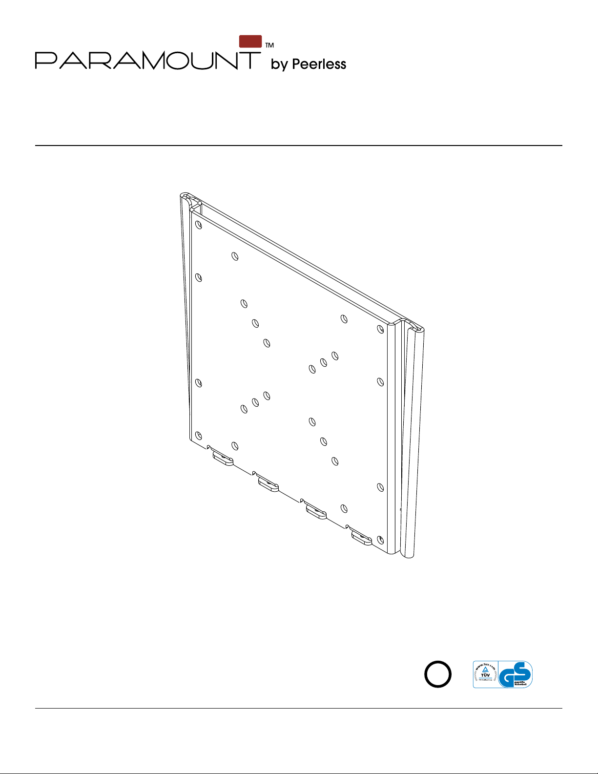
Installation and Assembly:
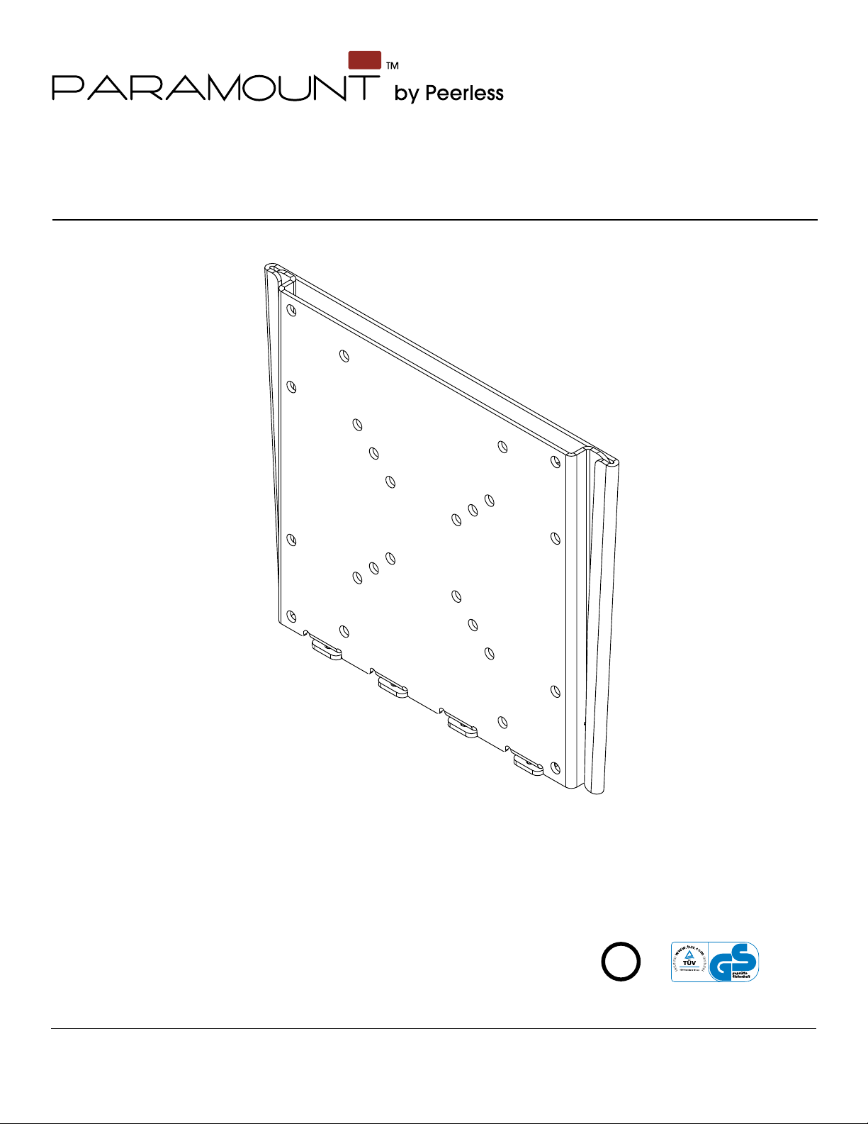
Paramount™ Flat Mount for 22" - 40" (56 - 102 cm)
LCD Screens
Model: PF632, PWV210/BK
Features:
• Screen held only .73" (1.85 cm) from wall for ultra-slim installation
• Screen adapter plate simply slides into the wall plate for quick and
easy installation
• Colors: Gloss Black
• Screen adapter plates included compatible with
VESA 75 mm, 100 mm, 200 mm x 100 mm, and 200 mm mounting
patterns
• Includes hardware for installation to wood studs, concrete, and
cinder block
3215 W. North Ave. • Melrose Park, IL • (800) 865-2112 or (708) 865-8870 • Fax: (708) 865-2941 • www.peerlessmounts.com
U
©
L
I
USC
D
2
:
6
0
7
0
8
0
1
0
0
Max UL Load Capacity: 115 lb (52.2 kg)
ISSUED: 11-19-07 SHEET #: 202-9248-6 11-04-09
Note: Read entire instruction sheet before you start installation and assembly.
WARNING
• Do not begin to install your Peerless product until you have read and understood the instructions and warnings
contained in this Installation Sheet. If you have any questions regarding any of the instructions or warnings, for US
customers please call Peerless customer care at 1-800-865-2112, for all international customers, please contact
your local distributor.
• This product should only be installed by someone of good mechanical aptitude, has experience with basic building
construction, and fully understands these instructions.
• Make sure that the supporting surface will safely support the combined load of the equipment and all attached
hardware and components.
• Never exceed the Maximum UL Load Capacity. See page one.
• If mounting to wood wall studs, make sure that mounting screws are anchored into the center of the studs. Use of
an "edge to edge" stud finder is highly recommended.
• Always use an assistant or mechanical lifting equipment to safely lift and position equipment.
• Tighten screws firmly, but do not overtighten. Overtightening can damage the items, greatly reducing their holding
power.
• This product is intended for indoor use only. Use of this product outdoors could lead to product failure and personal
injury.
• This product was designed to be installed on the following wall construction only;
WALL CONSTRUCTION HARDWARE REQUIRED
• Wood Stud Included
• Wood Beam Included
• Solid Concrete Included
• Cinder Block Included
• Metal Stud Do not attach except with Peerless Metal Stud Accessory Kit - ACC215;
(not evaluated by UL)
• Brick Contact Qualified Professional (not evaluated by UL)
• Other or unsure? Contact Qualified Professional
Tools Needed for Assembly
• stud finder ("edge to edge" stud finder is recommended)
• phillips screwdriver
• drill
• 5/16" (8 mm) bit for concrete and cinder block wall
• 5/32" (4 mm) bit for wood stud wall
• level
Table of Contents
Parts List.................................................................................................................................................................................3
Installation to Single Wood Stud Wall .....................................................................................................................................4
Installation to Solid Concrete or Cinder Block ........................................................................................................................5
Attaching Mounting Plate to Screen with VESA Mounting Patterns .......................................................................................6
Installing and Removing Flat Panel Screen............................................................................................................................8
2 of 36
ISSUED: 11-19-07 SHEET #: 202-9248-6 11-04-09
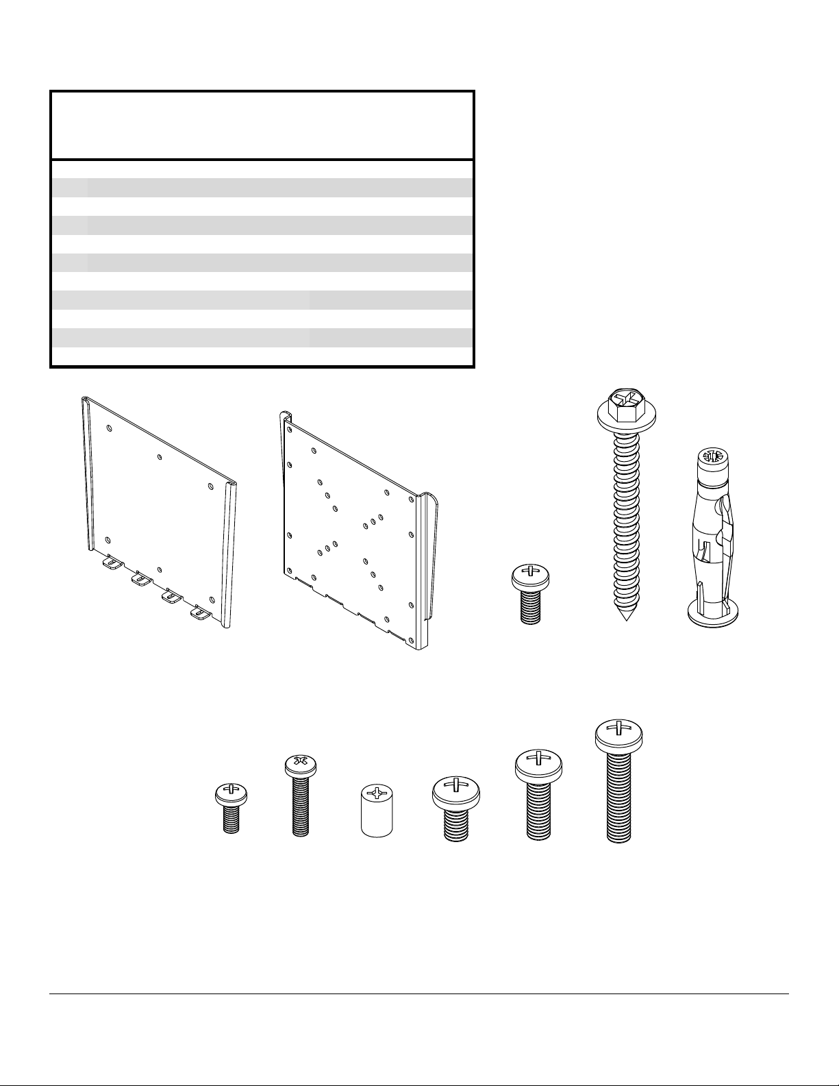
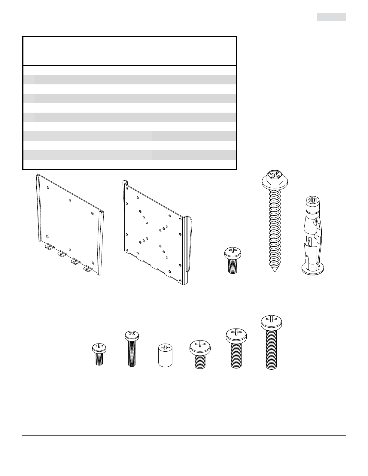
Before you begin, make sure all parts shown are included with your product.
A
Parts may appear slightly different than illustrated.
Parts List
Description
wall plate 1 095-P1498
mounting plate 1 095-P1499
B
M5 x 12 mm phillips screw 4 520-1027
C
#14 x 2.5" wood screw 2 5S1-015-C03
D
concrete anchor 2 590-0320
E
M4 x 10 mm phillips screw 4 504-9012
F
M4 x 20 mm phillips screw 4 504-9020
G
retaining spacer 4 590-5005
H
M6 x 12 mm phillips screw 4 520-1128
J
M6 x 20 mm phillips screw 4 520-9402
K
M6 x 30 mm phillips screw 4 510-9109
L
Qty. Part #
A
F
B
GH
3 of 36
CD
J KL
ISSUED: 11-19-07 SHEET #: 202-9248-6 11-04-09
E
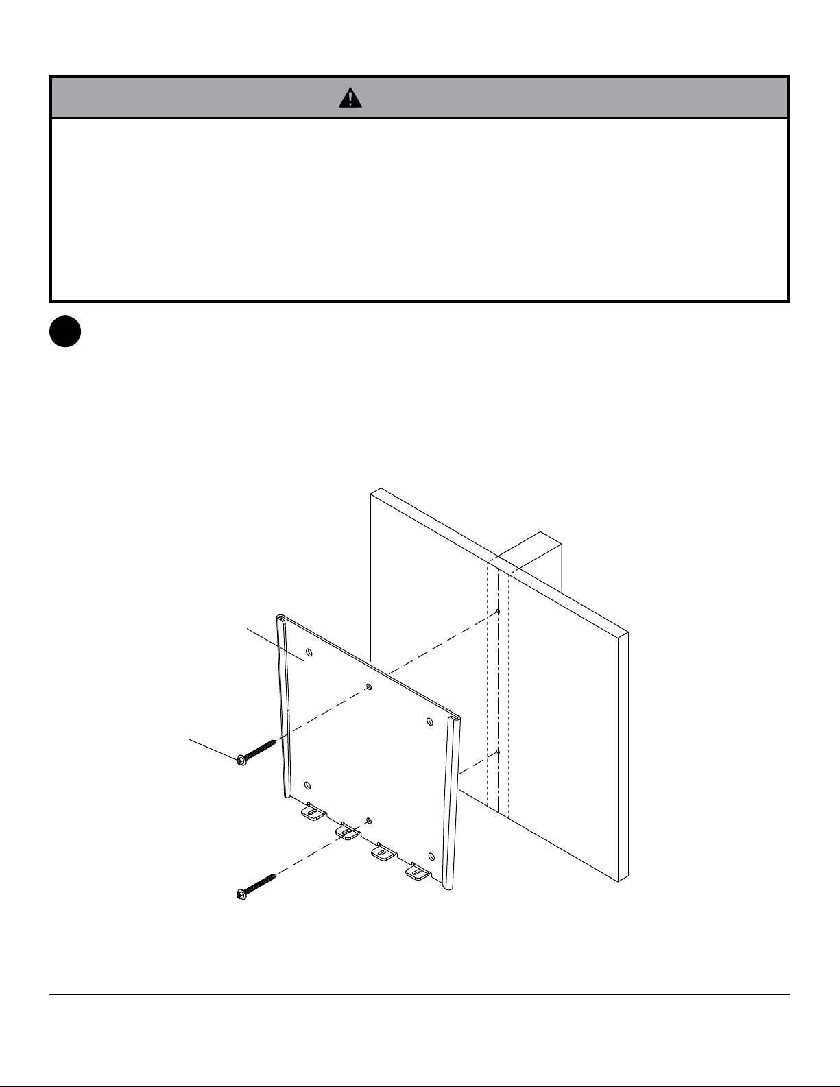
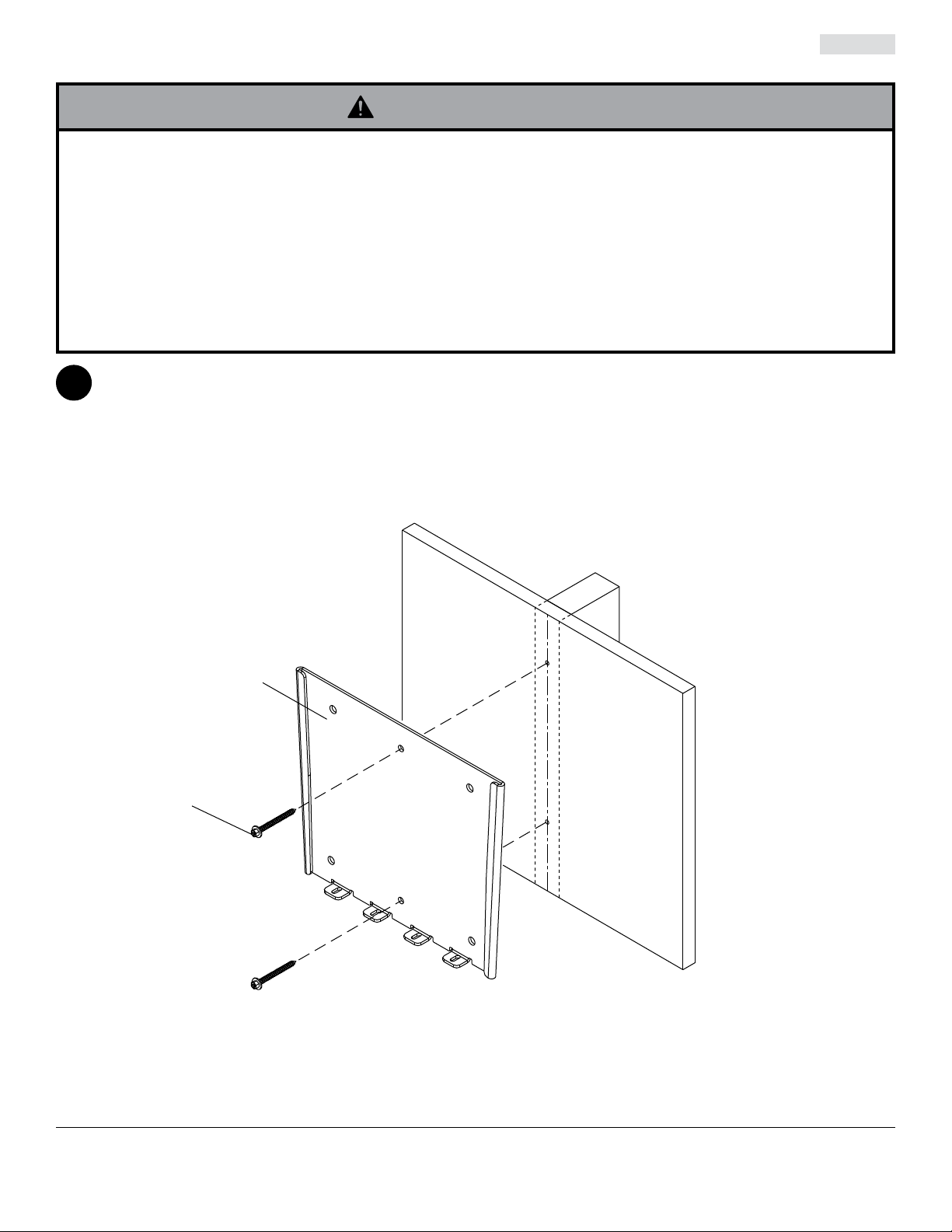
Installation to Single Wood Stud Wall
WARNING
• Installer must verify that the supporting surface will safely support the combined load of the equipment and all
attached hardware and components.
• Tighten wood screws so that wall plate is firmly attached, but do not overtighten. Overtightening can damage the
screws, greatly reducing their holding power.
• Never tighten in excess of 80 in. • lb (9 N.M.).
• Make sure that mounting screws are anchored into the center of the stud. The use of an "edge to edge" stud finder
is highly recommended.
• Hardware provided is for attachment of mount through standard thickness drywall or plaster into wood studs. Install-
ers are responsible to provide hardware for other types of mounting situations (not evaluated by UL).
Use a stud finder to locate the edges of the stud. Use of an edge-to-edge stud finder is highly recommended.
1
Based on its edges, draw a vertical line down the stud’s center. Place wall plate (A) on wall as a template, making
sure that the two mounting holes are on the stud centerline. Level wall plate, and mark the center of the two holes.
Drill two 5/32" (4 mm) dia. holes 2.5" (64 mm) deep. Make sure that the wall plate is level, secure it using two
#14 x 2.5" wood screws (D) as shown.
Skip to step 2.
D
A
4 of 36
ISSUED: 11-19-07 SHEET #: 202-9248-6 11-04-09
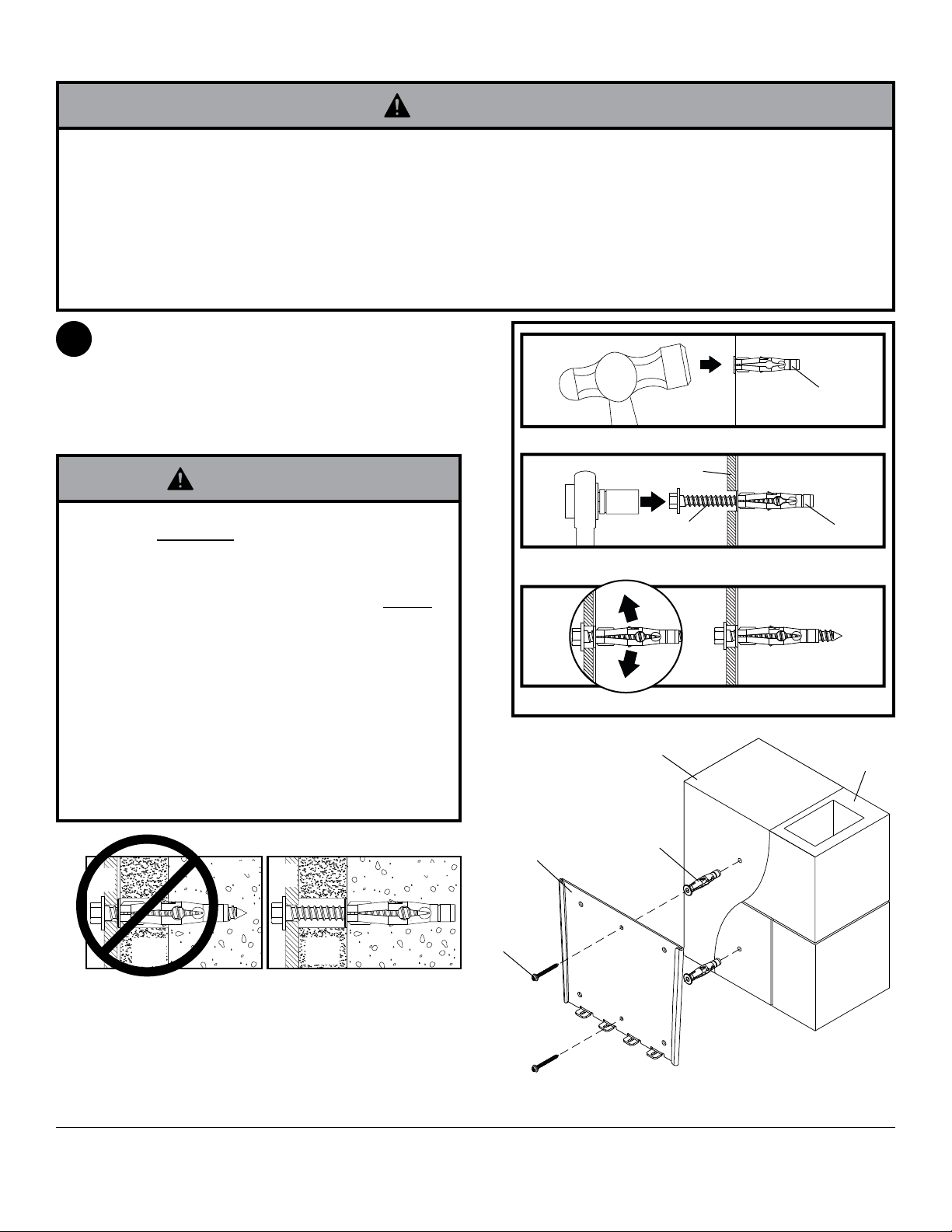
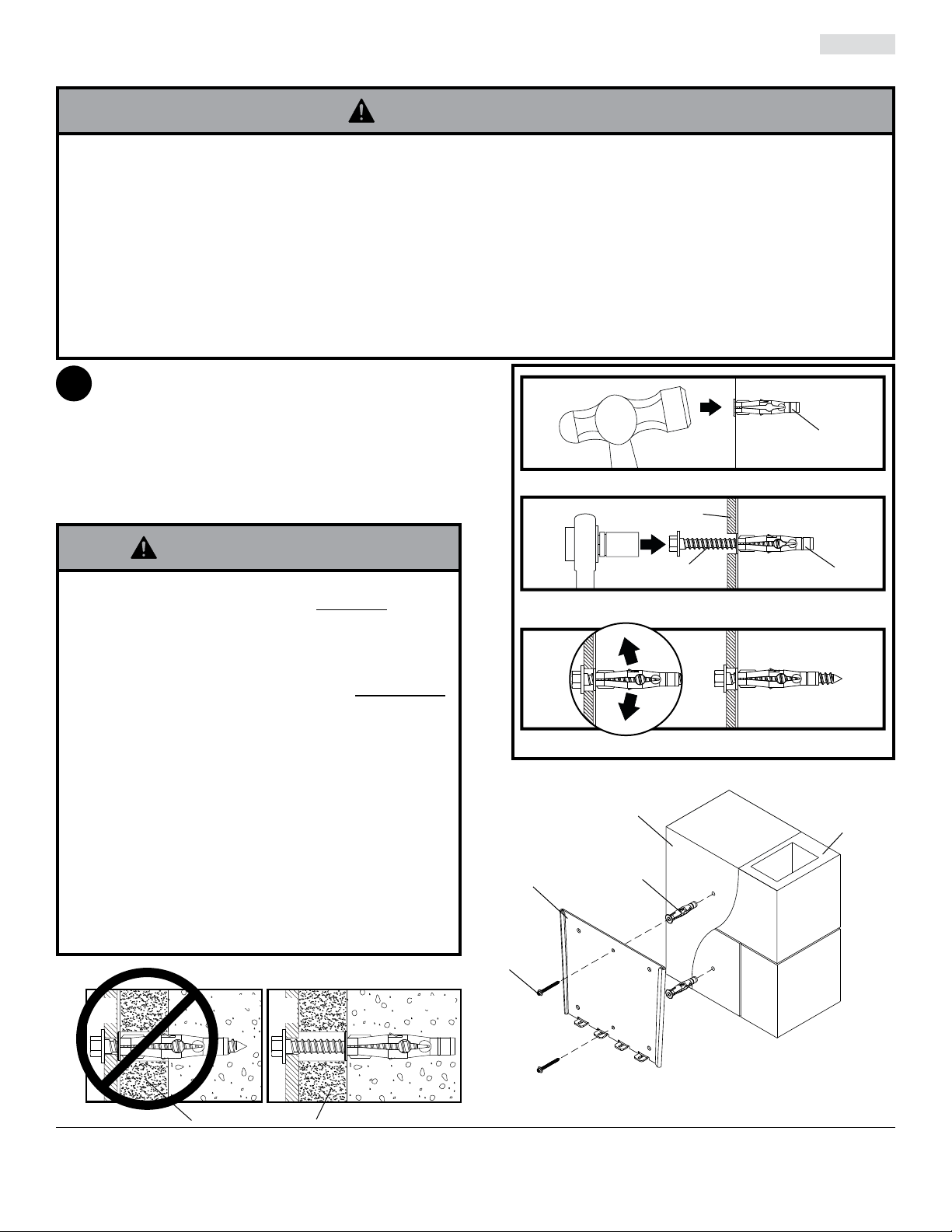
Installation to Solid Concrete or Cinder Block
WARNING
• When installing Peerless wall mounts on cinder block, verify that you have a minimum of 1-3/8" (35 mm) of actual
concrete thickness in the hole to be used for the concrete anchors. Do not drill into mortar joints! Be sure to mount
in a solid part of the block, generally 1" (25 mm) minimum from the side of the block. Cinder block must meet
ASTM C-90 specifications. It is suggested that a standard electric drill on slow setting is used to drill the hole
instead of a hammer drill to avoid breaking out the back of the hole when entering a void or cavity.
• Concrete must be 2000 psi density minimum. Lighter density concrete may not hold concrete anchor.
• Make sure that the supporting surface will safely support the combined load of the equipment and all attached hard-
ware and components.
Make sure that wall plate (A) is level, use it as a
1
template to mark two mounting holes. Drill two 5/16"
(8 mm) dia. holes to a minimum depth of 2.5"
(64 mm). Insert anchors (E) in holes flush with wall
as shown. Place wall plate over anchors and secure
with two #14 x 2.5" screws (D). Level, then tighten
all fasteners.
1
Drill holes and insert anchors (E).
concrete
surface
E
WARNING
• Tighten screws so that wall plate is firmly attached,
but do not overtighten. Overtightening can damage
screws, greatly reducing their holding power.
• Never tighten in excess of 80 in. • lb (9 N.M.).
• Always attach concrete expansion anchors directly
to load-bearing concrete.
• Never attach concrete expansion anchors to
concrete covered with plaster, drywall, or other
finishing material. If mounting to concrete surfaces
covered with a finishing surface is unavoidable (not
evaluated by UL), the finishing surface must be
counterbored as shown below. Be sure concrete
anchors do not pull away from concrete when
tightening screws. If plaster/drywall is thicker than
5/8" (16 mm), custom fasteners must be supplied by
installer (not evaluated by UL).
INCORRECT CORRECT
wall
plate
concrete
wall
plate
concrete
D
A
E
2
Place plate (A) over anchors (E) and secure with screws (D).
3
Tighten all fasteners.
SOLID
A
CONCRETE
E
CINDER
BLOCK
CUTAWAY VIEW
plaster/
dry wall
plaster/
dry wall
D
5 of 36
ISSUED: 11-19-07 SHEET #: 202-9248-6 11-04-09
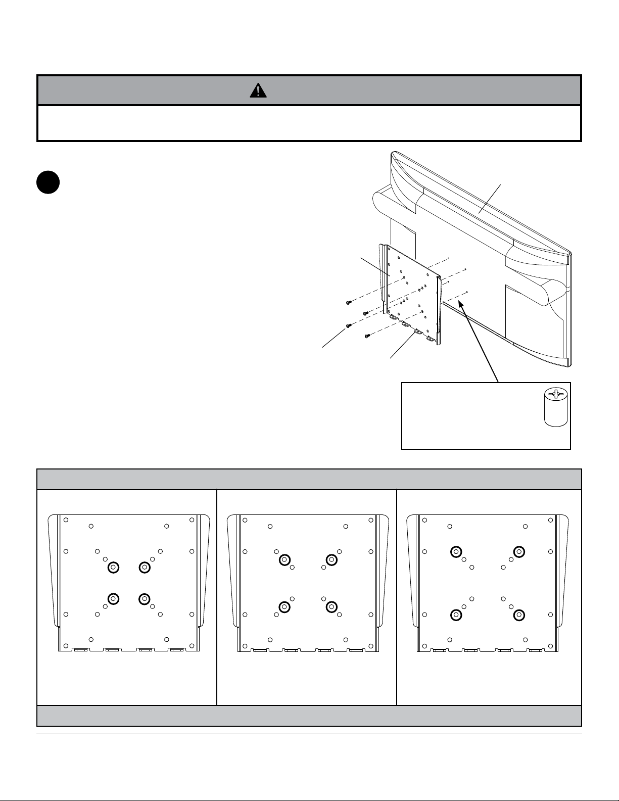
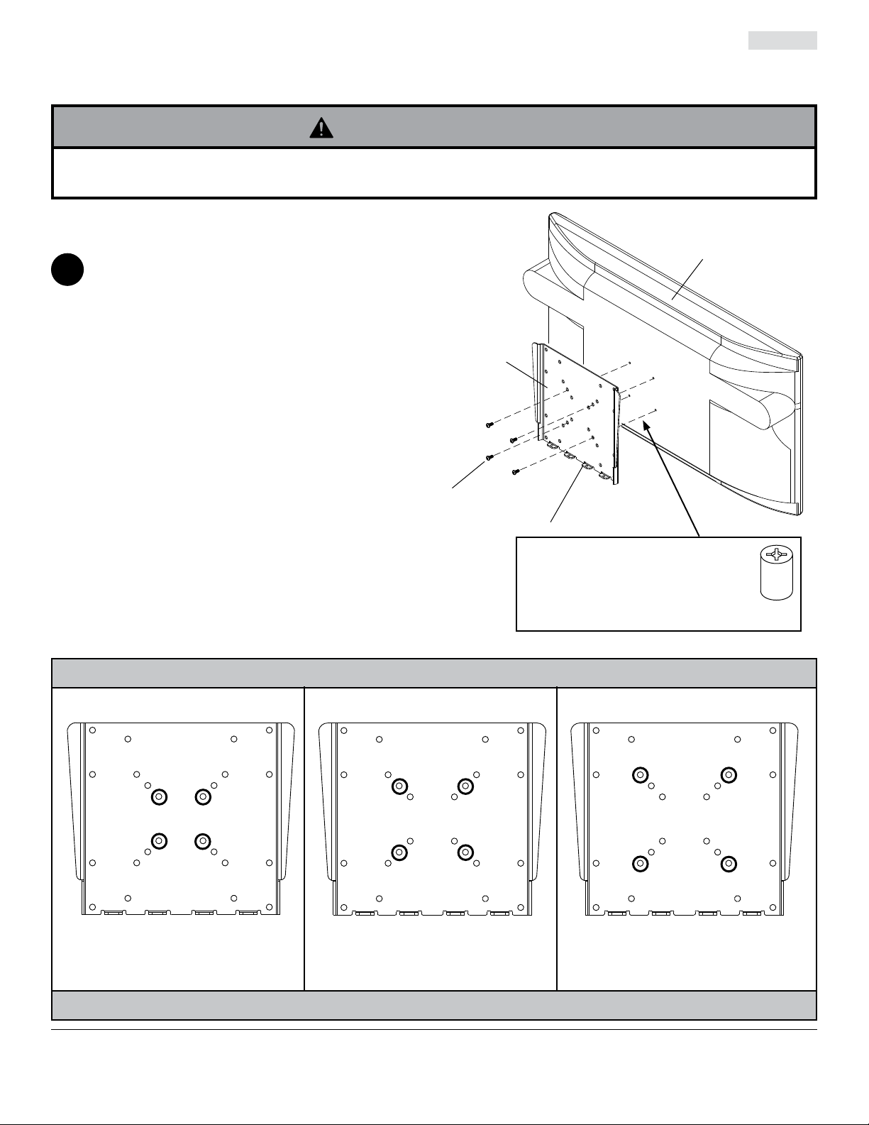
Attaching Mounting Plate to Screen
NOTE: For VESA® 200 x 100, 120 x 180 or 200 x 200 hole patterns, see following page.
WARNING
• If screws don't get three complete turns in the screen inserts or if screws bottom out and bracket is still not tightly
secured, damage may occur to screen or product may fail.
For VESA® 50, 75 or 100 Mounting Pattern:
Choose hole pattern as shown in detail 1 for VESA 50,
2
75 or 100 mounting pattern. Attach mounting plate (B)
to back of screen using four M4 x 10 mm screws (F) as
shown.
NOTE: Be certain bottom flanges of mounting plate (B)
face toward bottom of screen.
*NOTE: If hole pattern is in a pocket, attach mounting
plate (B) to back of screen using four M4 x 20 mm
screws (G) and four retaining spacers (H) as indicated.
Skip to step 3.
F or G
B
BOTTOM
FLANGES
SCREEN
*For screens with a hole
pattern in a pocket, spacers (H)
go between mounting
plate (B) and screen when
using screw (G).
H
Mounting Patterns
®
VESA
75 VESA® 100VESA® 50
6 of 36
DETAIL 1
ISSUED: 11-19-07 SHEET #: 202-9248-6 11-04-09
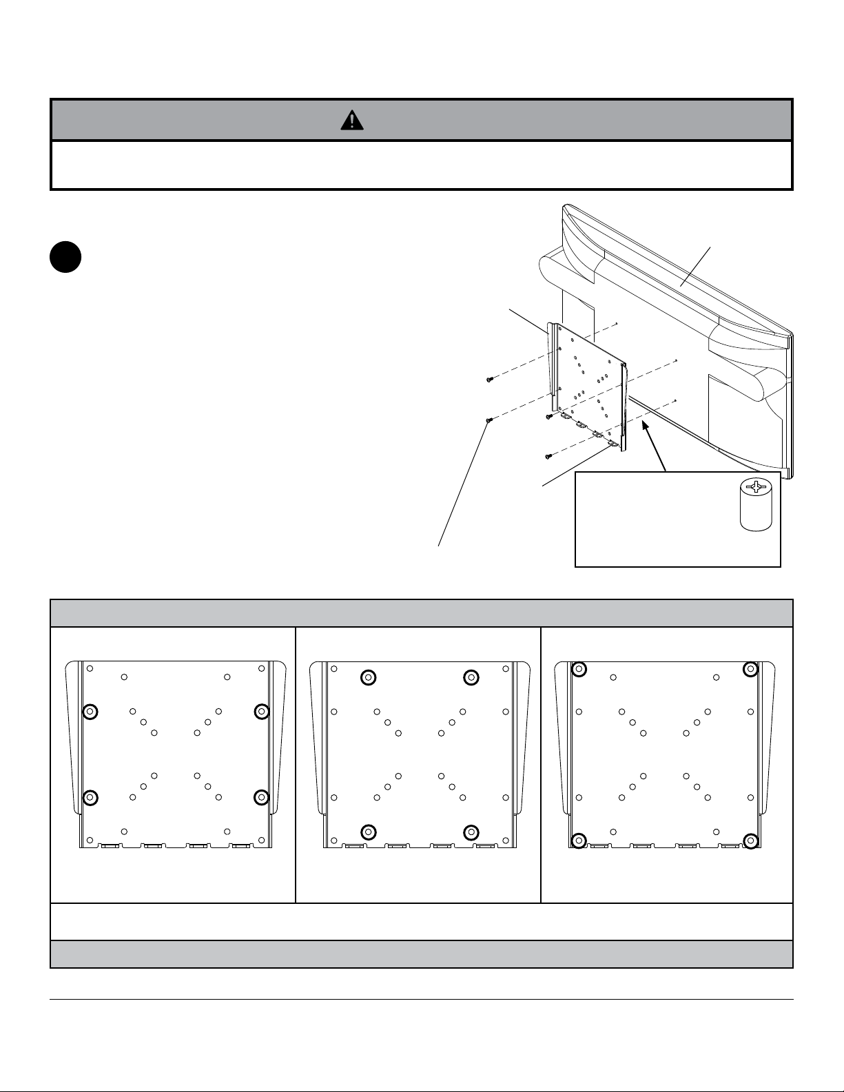
Attaching Mounting Plate to Screen with VESA® 200 x 100, 120 x 180 or
200 x 200 Mounting Pattern
WARNING
• If screws don't get three complete turns in the screen inserts or if screws bottom out and bracket is still not tightly
secured, damage may occur to screen or product may fail.
FOR VESA® 200 x 100, 120 x 180 or 200 x 200
MOUNTING PATTERN:
Choose hole pattern as shown in detail 2 for VESA
2
200 x 100, 120 x 180 or 200 x 200 mounting pattern
and for fasteners to use. Attach mounting plate (B) to
back of screen using four screws (F, G, J, K, or L) as
shown.
NOTE: Be certain bottom flanges of mounting plate
face toward bottom of screen.
*NOTE: If hole pattern is in a pocket, attach mounting
plate (B) to back of screen using four M4 x 20 mm
screws (G) and four retaining spacers (H) as indicated.
NOTE: If screw (J) gets less than three threads of
engagement, attach mounting plate (B) to back of
screen using four M6 x 20 mm screws (K). If screw (K)
still gets less than three threads of engagement, use
four M6 x 30 mm screws (L).
F, G, J, K or L
B
BOTTOM
FLANGES
*For screens with a
hole pattern in a pocket,
spacers (H) go between
mounting plate (B) and
screen when using
screws (G).
SCREEN
H
Mounting Patterns
VESA
M4 x 10 mm screws (F) or
M4 x 20 screws (G) with spacer (H)
NOTE: Fastener selection may vary for specific screens. If you have any questions for the correct fasteners to use for your
particular screen, call customer care.
M4 x 10 mm screws (F) or
M4 x 20 screws (G) with spacer (H)
®
120 x 180 VESA® 200 x 200VESA® 200 x 100
M6 x 12 mm screws (J),
M6 x 20 mm screws (K) or
M6 x 30 mm screws (L)
DETAIL 2
7 of 36
ISSUED: 11-19-07 SHEET #: 202-9248-6 11-04-09
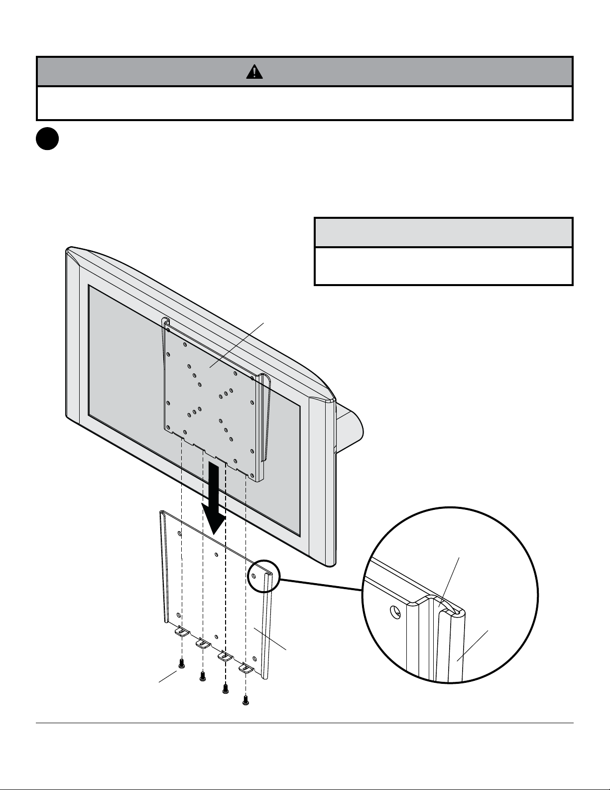
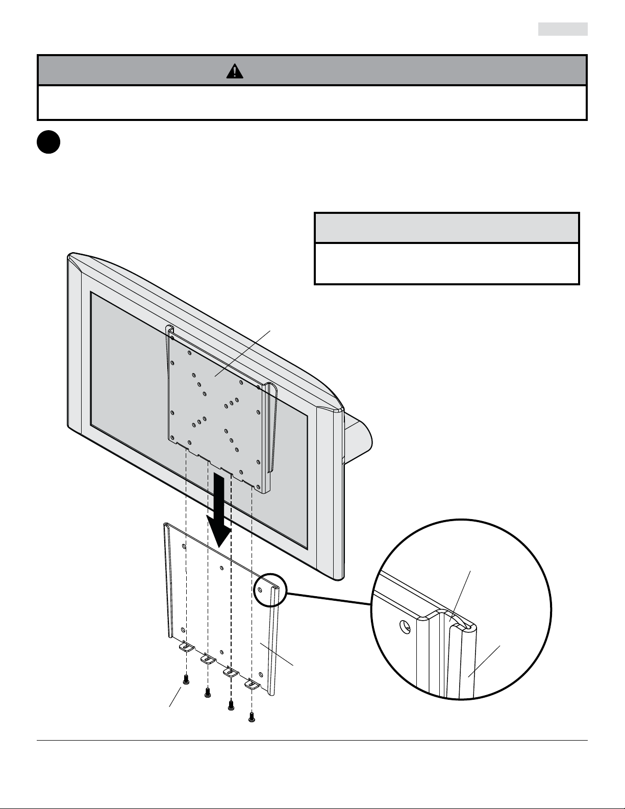
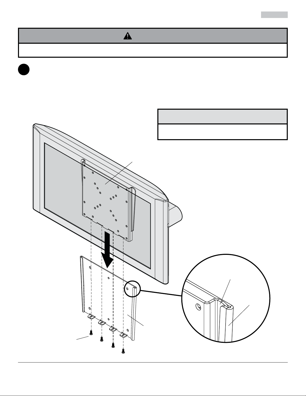
Installing and Removing Flat Panel Screen
WARNING
• Do not lift more weight than you can handle. Use additional man power or mechanical lifting equipment to safely
handle placement of the screen.
Attach mounting plate (B) to wall plate (A) by sliding flanges of mounting plate (B) into hook flanges of wall
3
plate (A). Secure mounting plate to wall plate using four M5 x 12 mm phillips screws (C) through bottom
flanges of wall plate (A) and into bottom flanges of mounting plate (B) as shown. Tighten screws securely.
To remove screen from mount, remove screws (C) and lift screen off of mount.
CAUTION
• Do not tighten screws with excessive force.
Overtightening can cause damage to mount.
B
C
B
FLANGES
A
HOOK
FLANGES
A
8 of 36
All other brand and product names are trademarks or registered trademarks of their respective owners.
ISSUED: 11-19-07 SHEET #: 202-9248-6 11-04-09
© 2009, Peerless Industries, Inc. All rights reserved.
Peerless Industries, Inc.
3215 W. North Ave.
Melrose Park, IL 60160
www.peerlessmounts.com
Instalación y ensamblaje:
Soporte de pared plano Paramount™ para pantallas LCD de
22" a 40" (56 - 102 cm)
Modelo: PF632, PWV210/BK
Características:
• Sostiene el televisor a sólo .73" (1.85 cm) de la pared para
proporcionar una instalación ultra recogida
• La placa adaptadora de la pantalla sencillamente se desliza
sobre la placa de pared para proporcionar una instalación
rápida y fácil
• Colores: Negro lustroso
• Incluye las placas adaptadoras para la pantalla compatibles
con las configuraciones de montaje de VESA 75 mm, 100
mm, 200 mm x 100 mm y 200 mm
• Incluye los accesorios para instalaciones en montantes de
madera, concreto y bloques de hormigón de escorias
3215 W. North Ave. • Melrose Park, IL • (800) 865-2112 or (708) 865-8870 • Fax: (708) 865-2941 • www.peerlessmounts.com
U
L
©
I
USC
D
2
:
6
0
7
0
8
0
1
0
0
Capacidad máxima de soportar carga por
UL
: 115 lb (52.2 kg)
PUBLICADO: 11-19-07 HOJA #: 202-9248-6 11-04-09
Español
Nota: Lea la hoja de instrucciones completa antes de comenzar la instalación y el ensamblaje.
ADVERTENCIA
• No comience a instalar su producto de Peerless hasta haber leído y entendido las instrucciones y las advertencias
contenidas en la Hoja de Instalación. Si tiene alguna pregunta acerca de cualquiera de las instrucciones o las advertencias, por favor, llame a Servicio al Cliente de Peerless al 1-800-865-2112 si está en EE. UU. Si es un cliente
internacional, por favor, comuníquese con su distribuidor local.
• Este producto sólo debe ser instalado por una persona que tenga una buena aptitud mecánica, que tenga experi-
encia en construcción básica de edificios y que entienda estas instrucciones en su totalidad.
• Asegúrese de que la superficie de apoyo sostendrá, con seguridad, la carga combinada del equipo y todos los
fijadores y componentes.
• Nunca sobrepase la capacidad máxima de soportar carga aceptada por Underwriters Laboratories.
9.
• Si va a instalar el producto en una pared con montantes de madera, asegúrese de que los tornillos de montaje
estén anclados en el centro de los montantes. Se recomienda utilizar un localizador de montantes de "borde a
borde".
• Siempre cuente con la ayuda de un asistente o utilice un equipo mecánico de izar para levantar y colocar el equipo
con más seguridad.
• Apriete los tornillos con firmeza, pero no en exceso. Apretarlos en exceso puede dañar los artículos y puede dis-
minuir significativamente su fuerza de fijación.
• Este producto está diseñado para uso en interiores solamente. Utilizar este producto en exteriores podría causar
fallas del producto y lesiones a individuos.
Vea la página
• Este producto fue diseñado para ser instalado en paredes con la siguiente construcción solamente:
CONSTRUCCIÓN DE LA PARED ACCESORIOS NECESARIOS
• Montante de madera Incluido
• Viga de madera Incluido
• Concreto macizo Incluido
• Bloque de hormigón de escorias Incluido
• Montante de metal No lo instale excepto con el juego de accesorios de Peerless para
montantes de metal - ACC215; (no evaluados por UL)
• Ladrillo Comuníquese con un profesional calificado (no evaluados por UL)
• ¿Otra superficie o no está seguro? Comuníquese con un profesional calificado
Herramientas necesarias para el ensamblaje
• localizador de montantes (se recomienda uno de “borde a borde”)
• destornillador phillips
• taladro
• broca de 5/16" (8 mm) para paredes de concreto y de bloque de hormigón de escorias
• broca de 5/32" (4 mm) para paredes con montantes de metal o de madera
• nivel
Tabla de contenido
Lista de piezas.....................................................................................................................................................................11
Instalación en una pared con montante de madera único ..................................................................................................12
Instalación en una pared de concreto macizo o de bloques de hormigón de escorias .......................................................13
Fijación de la placa de montaje a pantallas con configuraciones de montaje VESA ..........................................................14
Instalación y desinstalación de la pantalla plana ................................................................................................................16
10 de 36
PUBLICADO: 11-19-07 HOJA #: 202-9248-6 11-04-09
Antes de comenzar, asegúrese de que su producto contiene todas las piezas que se muestran.
Las piezas pueden verse un poco distintas a la ilustración.
Lista de piezas
Descripción Cantidad
A placa de pared 1 095-P1498
placa de montaje
B
C tornillo phillips M5 x 12 mm 4 520-1027
D tornillo para madera de N.° 14 x 2.5" 2 5S1-015-C03
E Anclaje para concreto 2 590-0320
F tornillo phillips M4 x 10 mm 4 504-9012
G tornillo phillips M4 x 20 mm 4 504-9020
H espaciador de retención 4 590-5005
J tornillos phillips M6 x 12 mm 4 520-1128
K tornillos phillips M6 x 20 mm 4 520-9402
L tornillos phillips M6 x 30 mm 4 510-9109
1 095-P1499
o
de pieza
N.
Español
A
F
GH
11 de 36
CDBE
J KL
PUBLICADO: 11-19-07 HOJA #: 202-9248-6 11-04-09
Español
Instalación en una pared con montante de madera único
ADVERTENCIA
• El instalador tiene que asegurarse de que la superficie de apoyo sostendrá, con seguridad, la carga combinada del
equipo y todos los fijadores y componentes.
• Apriete los tornillos de madera de manera que la placa de pared se fije firmemente, pero no en exceso. Apretarlos en
exceso puede dañar los tornillos y puede disminuir significativamente su fuerza de fijación.
• Nunca apriete a más de 80 pulg-lb (9 N•m).
• Asegúrese de que los tornillos de montaje estén anclados en el centro del montante. Se recomienda utilizar un localizador de montantes de “borde a borde”.
• Los accesorios para la instalación que se proveen son para fijar el soporte a montantes de madera a través de
tabique de yeso-cartón o yeso de espesor estándar. Los instaladores son responsables de suministrar los accesorios
necesarios para otros tipos de instalaciones (no evaluados por UL).
Utilice un localizador de montantes para localizar los bordes del montante. Se recomienda utilizar un localizador de
1
montantes de "borde a borde". Tomando los bordes como punto de referencia, trace una línea vertical por el centro
del montante. Coloque la placa de pared (A) en la pared para utilizarla como plantilla; asegúrese de que los dos
agujeros de montaje estén sobre la línea que trazó por el centro. Nivele la placa de pared y marque el centro de
los dos agujeros. Taladre dos agujeros de 5/32" (4 mm) de diámetro y 2.5" (64 mm) de profundidad. Asegúrese de
que la placa esté nivelada, fíjela utilizando dos tornillos para madera de 14 x 2.5" (D), como se muestra.
Pase al paso 2.
D
A
12 de 36
PUBLICADO: 11-19-07 HOJA #: 202-9248-6 11-04-09
Instalación en una pared de concreto macizo o de bloques
Español
de hormigón de escorias
ADVERTENCIA
• Cuando vaya a instalar soportes de pared de Peerless en bloques de hormigón de escorias, asegúrese de que
cuente con una capa de concreto de un grosor mínimo de 1-3/8" en el agujero, que pueda usar para los anclajes
para concreto. ¡No taladre en juntas de argamasa! Asegúrese de hacer la instalación en la parte sólida del bloque,
por lo general, a un mínimo de 1" del extremo del bloque. Los bloques de hormigón de escorias tienen que cumplir
las especificaciones de la ASTM C-90. Se sugiere utilizar un taladro eléctrico convencional a baja velocidad para
hacer el agujero en vez de un taladro percutor para no perforar el fondo del agujero al entrar en un vacío o una
cavidad.
• El concreto tiene que tener una densidad mínima de 2,000 psi. Es posible que un concreto de menos densidad no
sostenga el anclaje para concreto.
• Asegúrese de que la superficie de apoyo sostendrá, con seguridad, la carga combinada del equipo y todos los
fijadores y componentes.
Asegúrese de que la placa de pared (A) esté nivelada
1
y utilícela como plantilla para marcar dos agujeros
de montaje. Taladre dos agujeros de 5/16" (8 mm) de
diámetro a una profundidad mínima de 2.5" (64 mm).
Inserte los anclajes (E) en los agujeros a ras con la
pared, como se muestra. Coloque la placa de pared
sobre los anclajes y fíjela con dos tornillos de 14 x
2.5" (D). Nivele y apriete todos los sujetadores.
ADVERTENCIA
• Apriete los tornillos de manera que la placa de
pared se fije firmemente, pero no en exceso. Apretarlos en exceso puede dañar los tornillos y puede
disminuir significativamente su fuerza de fijación.
• Nunca apriete a más de 80 pulg-lb (9 N•m).
• Siempre fije los anclajes para concreto directamente
en la pared que sostiene la carga.
• Nunca fije los anclajes para concreto a una pared de
concreto recubierta con yeso, tabique de yeso-cartón
u otro material de acabado. Si es inevitable hacer la instalación en una superficie de concreto recubierta con
una superficie de acabado (no evaluados por UL), la
superficie de acabado tiene que ser escariada, como
se muestra abajo. Asegúrese de que los anclajes para
concreto no se separen del concreto cuando apriete
los tornillos. Si el grosor de la capa de yeso o tabique
de yeso-cartón tiene un grosor mayor de 5/8", el instalador tiene que suministrar las fijaciones especiales
(no evaluados por UL).
1
TECHO DE CONCRETO
E
Taladre los agujeros e inserte los anclajes (E).
2
A
D
Coloque la placa (A) sobre los anclajes (E) y fíjela con los
tornillos (D).
3
Apriete todas las fijaciones.
bloque de
concreto macizo
A
E
hormigón de
escorias
E
INCORRECTO
concreto
A A
VISTA EN CORTE
yeso / tabique de yeso-cartón
CORRECTO
concreto
13 de 36
D
PUBLICADO: 11-19-07 HOJA #: 202-9248-6 11-04-09
Español
Fijación de la placa de montaje a la pantalla
Nota: En el caso de las configuraciones de montaje VESA® 200 x 100, 120 x 180 o 200 x 200, pase a la próxima página.
ADVERTENCIA
• Si no se les da tres vueltas completas a los tornillos en los insertos de la pantalla o si los tornillos topan fondo y el
soporte todavía no está firme, se podría dañar la pantalla o el producto podría no funcionar bien.
En el caso de la configuración de montaje VESA®
50, 75 ó 100:
Seleccione la configuración de montaje, como
2
se muestra en el detalle 1, que corresponda a la
configuración de montaje VESA 50, 75 ó 100. Fije la
placa de montaje (B) a la parte trasera de la pantalla
usando cuatro tornillos de M4 x 10 mm (F), como se
muestra.
Nota: Cerciórese de que las pestañas inferiores de la
placa de montaje (B) apunten hacia la parte inferior
de la pantalla.
*Nota:
Si la configuración de agujeros está en una
cavidad, fije la placa de montaje (B) a la parte trasera
de la pantalla usando cuatro tornillos de M4 x 20 mm
(G) y cuatro espaciadores de retención (H), como se
indica.
Pase al paso 3.
B
F o G
PESTAÑAS INFERIORES
PANTALLA
VESA
®
50
*En el caso de las pantallas que
tienen la configuración de agujeros
en una cavidad, los espaciadores (H)
van entre la placa de montaje (B) y la
pantalla cuando use el tornillo (G).
Configuraciones de montaje
VESA
®
75
VESA
®
100
H
14 de 36
DETALLE 1
PUBLICADO: 11-19-07 HOJA #: 202-9248-6 11-04-09

Español
Fijación de la placa de montaje a pantallas con configuraciones de montaje
VESA
®
200 x 100, 120 x 180 ó 200 x 200
ADVERTENCIA
• Si no se les da tres vueltas completas a los tornillos en los insertos de la pantalla o si los tornillos topan fondo y el
soporte todavía no está firme, se podría dañar la pantalla o el producto podría no funcionar bien.
En el caso de las configuraciones de montaje de
VESA® 200 x 100, 120 x 180 ó 200 x 200:
Seleccione la configuración de montaje, como
se muestra en el detalle 2, que corresponda a la
configuración de montaje VESA 200 x 100, 120 x
2
180 ó 200 x 200. Fije la placa de montaje (B) a la
parte trasera de la pantalla usando cuatro tornillos (F,
G, J, K o L), como se muestra.
Nota: Cerciórese de que las pestañas inferiores de la
placa de montaje apunten hacia la parte inferior de la
pantalla.
*Nota:
Si la configuración de agujeros está en una
cavidad, fije la placa de montaje (B) a la parte trasera
de la pantalla usando cuatro tornillos de M4 x 20 mm
(G) y cuatro espaciadores de retención (H), como se
indica.
Nota: Si los tornillos (J) enroscan menos de tres
vueltas, fije la placa de montaje (B) a la parte trasera
de la pantalla utilizando cuatro tornillos de M6 x 20
mm (K). Si los tornillos (K) todavía enroscan menos
de tres vueltas, use cuatro tornillos de M6 x 30 mm
(L).
B
F, G, J,
K o L
PESTAÑAS INFERIORES
*En el caso de las pantallas
que tienen la configuración de
agujeros en una cavidad, los
espaciadores (H) van entre la placa
de montaje (B) y la pantalla cuando
use el tornillo (G).
PANTALLA
H
Configuraciones de montaje
VESA
Tornillos de M4 x 10 (F) o
Tornillos de M4 x 20 (G)
con espaciador (H)
Nota: La selección de sujetadores puede variar dependiendo de la pantalla. Si tiene alguna pregunta acerca de los sujetadores
adecuados para utilizar con una pantalla en particular, llame a servicio al cliente.
Tornillos de M4 x 10 (F) o
Tornillos de M4 x 20 (G)
®
120 x 180 VESA® 200 x 200VESA® 200 x 100
con espaciador (H)
Tornillos de M6 x 12 mm (J),
Tornillos de M6 x 20 mm (K) o
Tornillos de M6 x 30 mm (L)
DETALLE 2
15 de 36
PUBLICADO: 11-19-07 HOJA #: 202-9248-6 11-04-09
Español
Instalación y desinstalación de la pantalla plana
ADVERTENCIA
• No levante más peso del que puede manejar. Cuente con otra persona que lo ayude o utilice un equipo mecánico
de izar para levantar y colocar la pantalla con seguridad.
Fije la placa de montaje (B) a la placa de pared (A) deslizando las pestañas de la placa de montaje (B) en las
3
pestañas de enganche de la placa de pared (A). Fije la placa de montaje a la placa de pared colocando 4 tornillos
phillips de M5 x 12 mm (C) a través de las pestañas inferiores de la placa de pared (A) y en las pestañas inferiores
de la placa de montaje (B), como se muestra. Apriete los tornillos firmemente.
Para quitar la pantalla del soporte, quite los tornillos (C) y levante la pantalla para sacarla del soporte.
PRECAUCIÓN
• No apriete los tornillos con fuerza excesiva.
Apretarlos en exceso puede dañar el soporte.
B
B
PESTAÑAS
A
PESTAÑAS DE
ENGANCHE
C
A
16 de 36
Cualesquiera otras marcas y nombres de productos son marcas comerciales o registradas de sus respectivos dueños.
PUBLICADO: 11-19-07 HOJA #: 202-9248-6 11-04-09
© 2009, Peerless Industries, Inc. Todos los derechos reservados.
Peerless Industries, Inc.
3215 W. North Ave.
Melrose Park, IL 60160
www.peerlessmounts.com

Installation et montage :
Support plat Paramount™ pour écrans LCD
de 22 à to 40 po (56 - 102 cm)
Modèle: PF632, PWV210/BK
Caractéristiques :
• Écran maintenu à 0,73 po (1.85 cm) seulement du mur pour une
installation ultra-mince.
• La plaque d’adaptation de l’écran se glisse simplement sur la plaque
murale pour une installation rapide et facile
• Couleurs : Noir brillant
• Les plaques d’adaptation de l’écran incluses sont compatibles avec
les normes de montage VESA 75 mm, 100 mm,
200 mm x 100 mm et 200 mm
• Inclut la visserie requise pour l’installation sur les montants en bois,
du béton et du bloc de béton
3215 W. North Ave. • Melrose Park, IL • (800) 865-2112 or (708) 865-8870 • Fax: (708) 865-2941 • www.peerlessmounts.com
U
©
L
I
USC
D
2
:
6
0
7
0
8
0
1
0
0
Capacité de charge maximale par l’UL établie:
115 lb (52.2 kg)
PUBLIÉ LE : 11-19-07 FEUILLE no : 202-9248-6 11-04-09

Français
Remarque : lisez entièrement la fiche d’instructions avant de commencer l’installation et l’assemblage.
AVERTISSEMENT
• Ne commencez pas à installer votre produit Peerless avant d’avoir lu et assimilé les instructions et les avertissements contenus dans cette fiche d’installation. Pour toute question concernant les instructions ou les avertissements, veuillez appeler le service à la clientèle de Peerless au 1-800-865-2112; tous les clients internationaux sont
priés de contacter leur distributeur local.
• Ce produit doit être installé uniquement par quelqu’un possédant une bonne aptitude à la mécanique, une expérience de la construction immobilière et ayant bien compris ces instructions.
• Assurez-vous que la surface de support puisse soutenir sans danger la charge totale de l’équipement ainsi que des
pièces et composants qui y sont attachés.
• Ne dépassez jamais la capacité de charge maximum établie par l’UL. Reportez-vous à la page 17.
• Lors d’une installation sur un mur à montants en bois, assurez-vous que les vis de montage sont ancrées au centre
des montants. L’utilisation d’un localisateur de montants « bord à bord » est fortement recommandée.
• Pour lever et positionner l’équipement en toute sécurité, faites-vous toujours aider par une autre personne ou utilisez un dispositif de levage mécanique.
• Serrez fermement les vis, mais sans excès. Un serrage excessif peut endommager les composants et en réduire
considérablement la capacité de support.
• Ce produit est conçu uniquement pour un usage intérieur. L’utilisation de ce produit à l’extérieur peut causer une
défaillance du produit et des blessures corporelles.
• Ce produit a été conçu uniquement pour une installation sur les types de murs ci-dessous :
TYPE DE MUR PIÈCES DE FIXATION REQUISES
• Montant en bois Incluses
• Poutre en bois Incluses
• Béton plein Incluses
• Bloc de béton de mâchefer Incluses
• Montant métallique Ne pas installer sur ce type de mur sauf à l’aide de l’ensemble d’accessoires
Peerless pour montants métalliques - ACC215; (non évalué UL)
• Brique Contacter un professionnel qualifié (non évalué UL)
• Autre, ou vous n’êtes pas sûr ? Contacter un professionnel qualifié
Outils nécessaires au montage
• localisateur de montants (un localisateur de montants « bord à bord » est recommandé)
• tournevis Phillips
• perceuse
• foret de 5/32 po (4 mm) pour les murs à montants en bois
• foret de 5/16 po (8 mm) pour les murs à block de béton
• niveau
Tabla de contenido
Lista de piezas..................................................................................................................................................................... 19
Instalación en una pared con montante de madera único .................................................................................................. 20
Instalación en una pared de concreto macizo o de bloques de hormigón de escorias ....................................................... 21
Fijación de la placa de montaje a pantallas con configuraciones de montaje VESA .......................................................... 22
Instalación y desinstalación de la pantalla plana ................................................................................................................ 24
18 sur 36
PUBLIÉ LE : 11-19-07 FEUILLE no : 202-9248-6 11-04-09

Avant de commencer, assurez-vous que toutes les pièces indiquées sont incluses avec le produit.
o
Il est possible que les pièces semblent légèrement différentes de l’illustration.
Liste des pièces
Description Qté
A plaque murale 1 095-P1498
B plaque de montage 1 095-P1499
C vis Phillips M5 x 12 mm 4 520-1027
vis à bois n
D
E ancrage pour béton 2 590-0320
F vis Phillips M4 x 10 mm 4 504-9012
G vis Phillips M4 x 20 mm 4 504-9020
H entretoise 4 590-5005
J vis Phillips M6 x 12 mm 4 520-1128
K vis Phillips M6 x 20 mm 4 520-9402
L vis Phillips M6 x 30 mm 4 510-9109
o
14 x 2,5 po
Pièce n
2 5S1-015-C03
Français
A
F
GH
19 sur 36
CDBE
J KL
PUBLIÉ LE : 11-19-07 FEUILLE no : 202-9248-6 11-04-09

Français
Installation sur un mur à montant en bois simple
AVERTISSEMENT
• L’installateur doit s’assurer que la surface de support pourra soutenir sans danger la charge combinée de
l’équipement, de toute sa visserie et de tous ses composants.
• Serrez les vis à bois de manière que la plaque murale soit fermement fixée, mais sans excès. Un serrage excessif
peut endommager les vis et en réduire considérablement le pouvoir de maintien.
• Ne serrez jamais à plus de 9 Nm (80 po-lb).
• Assurez-vous que les vis de montage sont ancrées au centre des montants. L’usage d’un localisateur de montants
« bord à bord » est fortement conseillé.
• La visserie est fournie pour fixer la monture à travers une cloison sèche ou du plâtre d’épaisseur standard et dans
des montants en bois. Il appartient aux installateurs de fournir la visserie nécessaire pour d’autres types de situations (non évalué UL).
Repérez les bords du montant à l’aide d’un localisateur de montants. L’utilisation d’un localisateur de montants «
1
bord à bord » est fortement recommandée. Après avoir repéré les bords, tracez une ligne verticale le long du centre
du montant. Posez la plaque murale (A) sur le mur comme gabarit, en veillant à ce que les deux trous de fixation
soient sur la ligne médiane du montant. Mettez la plaque murale à niveau et marquez le centre des deux trous.
Percez deux trous de 5/32 po (4 mm) de dia. et de 2.5 po (64 mm) de profondeur. Assurez-vous que la plaque
murale est de niveau et fixez-la à l’aide de deux vis à bois n
Passez à l’étape 2.
o
14 x 2.5 po (D) comme illustré.
D
MONTANT
A
20 sur 36
PUBLIÉ LE : 11-19-07 FEUILLE no : 202-9248-6 11-04-09

Français
Installation sur du béton plein ou un bloc de béton de mâchefer
AVERTISSEMENT
• Si vous installez des montures murales Peerless sur un bloc de béton de mâchefer, vérifiez que vous disposez d’une
épaisseur de béton d’au moins 0,34 cm (1 3/8 po) dans le trou destiné aux ancrages de béton. Ne percez pas dans
les joints de mortier ! Veillez à effectuer le montage dans une partie pleine du bloc, généralement à au moins 2,5 cm
(1 po) du côté du bloc. Le bloc de béton de mâchefer doit être conforme aux spécifications de l’ASTM C-90. Pour
percer le trou, il est conseillé d’utiliser une perceuse électrique standard sur un réglage bas au lieu d’un marteau perforateur, afin d’éviter de briser la partie arrière du trou lorsque vous pénétrez un vide ou une cavité.
• Le béton doit avoir une densité minimale de 2 000 psi. Un béton de densité moindre risquerait de ne pas retenir un
ancrage de béton.
• Assurez-vous que la surface de support pourra soutenir sans danger la charge combinée de l’équipement, de toute sa
visserie et de tous ses composants.
Assurez-vous que la plaque murale (A) est de
1
niveau et utilisez-la comme gabarit pour marquer
l’emplacement des deux trous de fixation. Percez
deux trous de 5/16 po (8 mm) de dia. à une
profondeur minimale de 2.5 po (64 mm). Insérez
les chevilles d’ancrage (E) dans les trous au ras
du mur comme illustré. Posez la plaque murale
sur les chevilles d’ancrage et attachez-la à l’aide
de deux vis n° 14 x 2.5 po (D). Assurez-vous
qu’elle est de niveau, puis serrez toutes les
fixations.
AVERTISSEMENT
• Serrez les vis de manière que la plaque murale soit
fermement fixée, mais sans excès. Un serrage excessif peut endommager les vis et en réduire considérablement le pouvoir de maintien.
• Ne serrez jamais à plus de 9 Nm (80 po-lb).
• Fixez toujours des ancrages de béton directement sur
du béton porteur.
• Ne fixez jamais d’ancrages sur du béton recouvert
de plâtre, une cloison sèche ou autre matériau de
finition. Si vous ne pouvez pas éviter d’effectuer le
montage sur du béton recouvert d’une surface de
finition (non évalué UL), celle-ci doit être chambrée,
comme indiqué ci-dessous. Assurez-vous que les ancrages de béton ne se séparent pas du béton lorsque
vous serrez les vis. Si l’épaisseur du plâtre / de la
cloison sèche dépasse 1,5 cm (5/8 po), des fixations
adaptées devront être fournies par l’installateur (non
évalué UL).
1
Percez des trous et insérez les ancrages (E).
2
A
D
Placez la plaque (A) sur les ancrages (E) et fixez avec
des vis (D).
3
Serrez toutes les fixations.
BLOC DE BÉTON
BÉTON PLEIN
A
E
DE MÂCHEFER
surface en
béton
E
E
plaque
mural
plâtre /
VUE EN COUPE
cloison sèche
INCORRECT
béton
plaque
mural
plâtre /
cloison sèche
CORRECT
béton
21 sur 36
D
PUBLIÉ LE : 11-19-07 FEUILLE no : 202-9248-6 11-04-09

Français
Fixation de la plaque de montage à l’écran
Remarque : Pour les configurations de trous VESA® 200 x 100, 120 x 180 ou 200 x 200, voir la page suivante.
AVERTISSEMENT
• Si les vis ne sont pas enfoncées de trois tours complets dans les inserts ou si elles sont serrées au maximum sans
parvenir à fixer solidement le support, l’écran peut être abîmé ou le produit détérioré.
Pour les normes de montage VESA® 50, 75 ou 100 :
Choisissez la configuration de trous illustrée dans le
dessin de détail 1 pour les normes de montage VESA
2
50, 75 ou 100 Fixez la plaque de montage (B) au
dos de l’écran à l’aide de quatre vis M4 x 10 mm (F)
comme illustré.
Remarque : Veillez à ce que les brides inférieures de
la plaque de montage (B) soient tournées vers le bas
de l’écran.
* Remarque : Si la configuration des trous est dans
un creux, attachez la plaque de montage (B) au dos
de l’écran à l’aide de quatre vis M4 x 20 mm (G) et de
quatre entretoises de retenue (H) comme indiqué.
Passez à l’étape 3.
B
ÉCRAN
F ou G
BRIDES
INFÉRIEURES
*Pour les écrans dont la configuration
de trous est dans un creux, les
entretoises (H) doivent être placées
entre la plaque de montage (B) et l’écran
lorsqu’on utilise la vis (G).
Normes de montage
H
VESA
®
50
VESA
22 sur 36
®
75
VESA
®
100
DESSIN DE DÉTAIL 1
PUBLIÉ LE : 11-19-07 FEUILLE no : 202-9248-6 11-04-09

Français
Fixation de la plaque de montage à un écran compatible à la norme de montage
VESA
®
200 x 100, 120 x 180 ou 200 x 200
AVERTISSEMENT
• Si les vis ne sont pas enfoncées de trois tours complets dans les inserts ou si elles sont serrées au maximum sans
parvenir à fixer solidement le support, l’écran peut être abîmé ou le produit détérioré.
POUR LA NORME DE MONTAGE
VESA® 200 x 100, 120 x 180 ou 200 x 200 :
Choisissez la configuration de trous illustrée dans
le dessin de détail 2 pour la configuration de
2
montage VESA 200 x 100, 120 x 180 ou 200 x 200
et le type de fixations à utiliser. Fixez la plaque de
montage (B) au dos de l’écran à l’aide de quatre
vis (F, G, J, K, ou L) comme illustré.
Remarque : Veillez à ce que les brides inférieures
de la plaque de montage soient tournées vers le
bas de l’écran.
* Remarque : Si la configuration des trous est
dans un creux, attachez la plaque de montage (B)
au dos de l’écran à l’aide de quatre vis M4 x 20
mm (G) et de quatre entretoises de retenue (H)
comme indiqué.
Remarque : Si la vis (J) ne se visse pas sur
au moins trois filetages, attachez la plaque de
montage (B) au dos de l’écran à l’aide de quatre
vis M6 x 20 mm (K). Si la vis (K) ne se visse
toujours pas sur au moins trois filetages, utilisez
quatre vis M6 x 30 mm (L).
BRIDES
INFÉRIEURES
F, G, J,
K ou L
B
*Pour les écrans dont la
configuration de trous
est dans un creux, les
entretoises (H) doivent être
placées entre la plaque
de montage (B) et l’écran
lorsqu’on utilise la vis (G).
ÉCRAN
H
Normes de montage
®
VESA
Vis M4 x 10 mm (F) ou
vis M4 x 20 (G) avec une entretoise (H)
Remarque : La sélection de fixations peut varier selon le type d’écran. Pour toute question concernant les fixations appropriées à
votre écran, veuillez appeler le service à la clientèle.
vis M4 x 20 (G) avec une entretoise (H)
Vis M4 x 10 mm (F) ou
120 x 180 VESA® 200 x 200VESA® 200 x 100
Vis M6 x 12 mm (J),
vis M6 x 20 mm (K) ou
vis M6 x 30 mm (L)
DESSIN DE DÉTAIL 2
23 sur 36
PUBLIÉ LE : 11-19-07 FEUILLE no : 202-9248-6 11-04-09

Français
Montage et démontage d’un écran plat
AVERTISSEMENT
• Ne soulevez pas une charge trop lourde pour vous. Pour positionner l’écran en toute sécurité, faites-vous aider par
une autre personne ou utilisez un dispositif de levage mécanique.
Fixez la plaque de montage (B) à la plaque murale (A) en glissant les brides de la plaque de montage (B)
3
dans les brides d’accrochage de la plaque murale(A). Fixez la plaque de montage à la plaque murale en
insérant 4 vis Phillips M5 x 12 mm (C) dans les brides inférieures de la plaque murale (A), puis dans les
brides inférieures de la plaque de montage (B) comme illustré. Serrez fermement les vis.
Pour retirer l’écran du support, retirez les vis (C) et soulevez-le hors du support.
ATTENTION
• Évitez de trop serrer les vis. Un serrage excessif
peut endommager le support.
B
C
B
BRIDES
A
BRIDES
D’ACCROCHAGE
A
24 sur 36
Tous les autres noms de marques et de produits sont des marques de commerce ou déposées de leurs propriétaires respectifs.
PUBLIÉ LE : 11-19-07 FEUILLE no : 202-9248-6 11-04-09
© 2009, Peerless Industries, Inc. Tous droits réservés.
Peerless Industries, Inc.
3215 W. North Ave.
Melrose Park, IL 60160
www.peerlessmounts.com

Anbringung und Zusammenbau:
Paramount™-Flachhalter für LCD-Bildschirme von 22 - 40 Zoll
(56 - 102 cm)
Modelle: PF632, PWV210/BK
Merkmale:
• Angebrachter Bildschirm steht für ultraflache Anbringung nur 1,85 cm
(0,73 Zoll) von der Wand ab
• Bildschirmadapterplatte gleitet einfach in die Wandplatte zwecks
schneller und einfacher Anbringung
• Farben: Schwarz glänzend
• Mitgelieferte Bildschirmadapterplatten kompatibel mit VESA 75 mm, 100
mm, 200 mm x 100 mm und 200 mm Montagemustern
• Einschließlich Befestigungsteile zur Anbringung an Holzständern, Beton
und Porenbetonstein
AUSGEGEBEN: 11-19-07 BLATT NR.: 202-9248-6 11-04-09
3215 W. North Ave. • Melrose Park, IL • (800) 865-2112 or (708) 865-8870 • Fax: (708) 865-2941 • www.peerlessmounts.com
U
L
©
I
USC
D
2
:
6
0
7
0
8
0
1
0
0
Maximale UL Tragfähigkeit: 115 lb (52.2 kg)

Deutsch
HINWEIS: Lesen Sie bitte das gesamte Anleitungsblatt durch, bevor Sie mit Anbringung und Zusammenbau beginnen.
ACHTUNG
• Beginnen Sie mit der Anbringung Ihres Peerless-Produkts erst, nachdem Sie die in dieser Montageanleitung
enthaltenen Anleitungen und Achtungshinweise gelesen und sich gründlich mit ihnen vertraut gemacht haben. Falls
Sie Fragen hinsichtlich irgendeiner der Anleitungen oder Achtungshinweise haben, wenden Sie sich in den USA bitte
an den Peerless-Kundendienst unter der Rufnummer 1-800-865-2112. Kunden im Ausland wenden sich bitte an den
örtlichen Vertragshändler.
• Dieses Produkt darf nur von Personen mit guten mechanischen Fähigkeiten montiert werden, die über Erfahrung in
den Grundlagen der Baukonstruktion verfügen und diese Anleitungen vollkommen verstehen.
• Vergewissern Sie sich, dass die tragende Fläche das Gesamtgewicht der Geräte und allen daran angebrachten
Befestigungsteilen und Komponenten sicher tragen kann.
• Die maximale UL Tragfähigkeit darf niemals überschritten werden. Siehe Seite 25.
• Achten Sie bei der Anbringung an Holzständern darauf, dass die Befestigungsschrauben jeweils in der Mitte der
Holzständer verankert sind. Am besten eignet sich ein Balkenfinder mit genauer Kantenanzeige.
• Ziehen Sie immer eine zusätzliche Person heran oder verwenden Sie mechanische Hebegeräte, um Geräte sicher
zu heben und zu positionieren.
• Ziehen Sie die Schrauben fest an, ohne sie zu überdrehen. Durch Überdrehen können die Teile beschädigt werden,
wodurch ihr Haltevermögen stark reduziert wird.
• Dieses Produkt ist nur für den Gebrauch innerhalb von Gebäuden bestimmt. Eine Verwendung dieses Produkts im
Freien kann zu Produktausfall und Personenschaden führen.
• Dieses Produkt wurde nur für die Anbringung an den folgenden Wandkonstruktionen ausgelegt:
Wandkonstruktion Erforderliche Befestigungsteile
• Holzständer Inbegriffen
• Holzbalken Inbegriffen
• Massivbeton Inbegriffen
• Porenbetonstein Inbegriffen
• Metallständer Nur Mit Metallständer-zubehörsatz Von Peerless Anbringen - ACC215;
• Ziegel Qualifizierten Fachmann Konsultieren
• Andere oder nicht sicher? Qualifizierten Fachmann Konsultieren
Für den Zusammenbau erforderliche Werkzeuge
• Balkenfinder (Balkenfinder mit genauer Kantenanzeige empfohlen)
• Kreuzschlitzschraubendreher
• Bohrer
• 5/16 Zoll (8 mm) Bit für Beton- und Porenbetonsteinwand
• 5/32 Zoll (4 mm) Bit für Holzständerwand
• Wasserwaage
Inhaltsverzeichnis
Teileliste ................................................................................................................................................................................27
Anbringung an Holzständerwand .........................................................................................................................................28
Anbringung an Massivbeton und Porenbetonstein ...............................................................................................................29
Befestigung Der Adapterplatte Am Bildschirm Unter Verwendung Von VESA-Montagemuster ...........................................30
Befestigung von Adapterhalterung an Bildschirm .................................................................................................................32
26 von 36
AUSGEGEBEN: 11-17-09 BLATT NR.: 202-9248-6 11-04-09

Deutsch
A
A
A
r
Vergewissern Sie sich vor Beginn der Arbeiten, dass alle dargestellten Teile mit Ihrem Produkt mitgeliefert wurden.
Teileliste
Beschreibung
Wandplatte
Montageplatte
B
M5 x 12 mm Kreuzschlitzschraube
C
Nr. 14 x 2.5 Zoll Sechskant-Holzschraube
D
Betondübel
E
M4 x 10 mm Kreuzschlitzschraube
F
M4 x 20 mm Kreuzschlitzschraube
G
bstandhalte
H
M6 x 12 mm Kreuzschlitzschraube
J
M6 x 20 mm Kreuzschlitzschraube
K
M6 x 30 mm Kreuzschlitzschraube
L
Die Teile können etwas anders als in der Abbildung aussehen.
nz. Teilenr.
1 095-P1498
1 095-P1499
4 520-1027
2 5S1-015-C03
2 590-0320
4 504-9012
4 504-9020
4 590-5005
4 520-1128
4 520-9402
4 510-9109
A
F
GH
27 von 36
CDBE
J KL
AUSGEGEBEN: 11-17-09 BLATT NR.: 202-9248-6 11-04-09

Deutsch
Anbringung an Wänden mit einer Holzständerreihe
ACHTUNG
• Bei der Anbringung muss darauf geachtet werden, dass die Wand die kombinierte Last von Bildschirm und allen Befestigungsteilen und
-komponenten tragen kann.
• Ziehen Sie die Schrauben fest genug an, dass die Wandplatte sicher befestigt ist, doch ohne sie zu überdrehen. Durch Überdrehen können die
Schrauben beschädigt werden, wodurch ihr Haltevermögen stark reduziert wird.
• Das Drehmoment darf 80 in. • lb (9 Nm.) auf keinen Fall überschreiten.
• Achten Sie darauf, dass die Befestigungsschrauben jeweils in der Mitte der Holzständer verankert werden. Am besten eignet sich ein Balkenfinder
mit genauer Kantenanzeige.
• Die mitgelieferten Befestigungsteile sind für die Befestigung des Halters durch Trocken- oder Putzwand standardmäßiger Stärke in Holzständer
vorgesehen. Für die Anbringung an anders konstruierten Wänden müssen andere (nicht UL-zugelassene) Befestigungsteile verwendet werden.
Bestimmen Sie die Kanten des Ständers mithilfe eines Balkenfinders. Am besten eignet sich ein Balkenfinder mit
1
genauer Kantenanzeige. Verwenden Sie die Kanten als Richtlinie und ziehen Sie eine senkrechte Linie entlang der
Mitte des Ständers. Legen Sie die Wandplatte (A) als Schablone an die Wand und achten Sie darauf, dass sich die
beiden Montagebohrungen auf der Mittellinie des Holzständers befinden. Richten Sie die Platte waagerecht aus
und markieren Sie den Mittelpunkt der Löcher. Bohren Sie zwei Löcher mit einem Durchmesser von 4 mm (5/32
Zoll) und einer Tiefe von 64 mm (2,5 Zoll). Achten Sie darauf, dass die Wandplatte waagerecht ist und befestigen
Sie sie wie abgebildet mit zwei Nr. 14 x 2.5 Zoll Holzschrauben (D).
FAHREN SIE MIT SCHRITT 2.
D
HOLZSTÄNDERWAND
A
28 von 36
AUSGEGEBEN: 11-17-09 BLATT NR.: 202-9248-6 11-04-09

Deutsch
Anbringung an Massivbeton und Porenbetonstein
ACHTUNG
• Bei der Anbringung von Peerless-Wandhaltern an Porenbetonstein muss sichergestellt werden, dass die tatsächliche Stärke des Betons, in
den das Loch für die Betondübel gebohrt wird, mindestens 35 mm (1 3/8 Zoll) beträgt. Bohren Sie nicht in Mörtelfugen! Achten Sie darauf,
dass die Anbringung an einem massiven Teil des Blocks erfolgt, im Allgemeinen mindestens 25 mm (1 Zoll) von der Blockseite entfernt. Die
Porenbetonsteine müssen den Spezifikationen der ASTM-Norm C-90 entsprechen. Wir empfehlen, zum Bohren des Lochs anstelle eines
Schlagbohrers einen standardmäßigen Elektrobohrer bei niedriger Einstellung zu verwenden, um zu verhindern, dass die Bohrungsrückseite beim
Eintritt in einen Leer- oder Hohlraum ausbricht.
• Die Betondruckfestigkeit muss mindestens 2000 psi betragen. In Beton mit geringerer Druckfestigkeit kann der Betondübel u. U. nicht halten.
• Vergewissern Sie sich, dass die Wand das Vierfache des Gesamtgewichts von Geräten und allen daran angebrachten Befestigungsteilen und
Komponenten sicher tragen kann.
Achten Sie darauf, dass die Wandplatte
1
(A) waagerecht ist und verwenden Sie sie
als Schablone zum Markieren der beiden
Montagebohrungen. Bohren Sie zwei Löcher mit
einem Durchmesser von 8 mm (5/16 Zoll) und
einer Mindesttiefe von 64 mm (2,5 Zoll). Stecken
Sie Dübel (E) in die Löcher, bis diese bündig mit
der Wand abschließen (siehe Abbildung rechts).
Halten Sie die Wandplatte auf den Dübeln fest
und befestigen Sie sie mit zwei Nr. 14 x 2.5 Zoll
Schrauben (D). Richten Sie sie waagerecht aus und
ziehen Sie dann sämtliche Befestigungsteile an.
ACHTUNG
• Ziehen Sie die Schrauben fest genug an, dass die Wandplatte
sicher befestigt ist, doch ohne sie zu überdrehen. Durch
Überdrehen können die Schrauben beschädigt werden, wodurch ihr
Haltevermögen stark reduziert wird.
• Das Drehmoment darf 80 in. • lb (9 Nm.) auf keinen Fall
überschreiten.
• Betonspreizdübel müssen stets direkt am tragenden Beton
angebracht werden.
• Betonspreizdübel dürfen auf keinen Fall an Beton befestigt
werden, der mit Verputz, Trockenwandmaterial oder anderem
Deckschichtmaterial bedeckt ist. Falls es nicht vermeiden lässt, die
Montage an einer Betonfläche mit Deckschicht vorzunehmen (nicht
UL-zugelassene), muss wie nachstehend dargestellt eine Senkung
in die Deckschicht gebohrt werden. Vergewissern Sie sich, dass die
Betondübel beim Anziehen der Schrauben nicht vom Beton weg
gezogen werden. Falls der Verputz bzw. das Trockenwandmaterial
dicker ist als 16 mm (5/8 Zoll), müssen von der für die Montage
zuständigen Person Spezialbefestigungsteile bereitgestellt werden
(nicht UL-zugelassene).
1
Bohren Sie Löcher und setzen Sie die Dübel (E) ein.
2
A
D
Legen Sie die Platte (A) über die Dübel (E) und befestigen Sie sie
mit Schrauben (D).
3
Ziehen Sie alle Befestigungsteile an.
MASSIVBETON
A
E
BEFESTIGUNGSFLÄCHE
E
PORENBETONSTEIN
E
WAND-
PLATTE
SCHNITTANSICHT
VERPUTZ/
RIGIPS
FALSCH RICHTIG
BETON
WAND-
PLATTE
VERPUTZ/
RIGIPS
BETON
29 von 36
D
AUSGEGEBEN: 11-17-09 BLATT NR.: 202-9248-6 11-04-09

Deutsch
Anbringung der Montageplatte am Bildschirm
HINWEIS: Siehe folgende Seite bzgl. VESA 200 x 100, 120 x 180 oder 200 x 200 Lochmuster.
ACHTUNG
• Sind die Schrauben nicht um drei volle Umdrehungen in die Löcher des Bildschirms eingeschraubt oder stoßen sie unten an und die Halterung ist
noch immer nicht sicher befestigt, kann der Bildschirm beschädigt werden oder das Produkt kann versagen.
Bei Montagemuster VESA® 50, 75 oder 100:
Wählen Sie für das VESA 50, 75 oder 100
Montagemuster das in der Detailansicht 1 gezeigte
2
Lochmuster. Befestigen Sie die Montageplatte (B) wie
abgebildet mit vier M4 x 10 mm Schrauben (F) an der
Bildschirmrückseite. HINWEIS: Achten Sie darauf,
dass die unteren Flansche der Montageplatte (B) zur
Unterseite des Bildschirms weisen.
*HINWEIS: Befestigen Sie die Montageplatte (B) mit vier
M4 x 20 mm Schrauben (G) und vier Abstandhaltern (H)
an der Bildschirmrückseite, wenn sich das Lochmuster
in einer Vertiefung befindet (siehe unten). Fahren Sie mit
Schritt 3 fort.
FAHREN SIE MIT SCHRITT 3.
B
BILDSCHIRM
F oder G
UNTERE FLANSCHE
MONTAGEMUSTER
*Bei Bildschirmen mit
Lochmuster in einer
Vertiefung werden
Abstandhalter (H)
zwischen Montageplatte
(B) und Bildschirm
angebracht, wenn die
Schrauben (G) verwendet
werden.
H
VESA
30 von 36
®
75 VESA® 100VESA® 50
DETAILANSICHT 1
AUSGEGEBEN: 11-17-09 BLATT NR.: 202-9248-6 11-04-09

Deutsch
Unter Verwendung der Montagemuster VESA 200 x 100, 120 x 180, und 200 x 200
ACHTUNG
• Sind die Schrauben nicht um drei volle Umdrehungen in die Löcher des Bildschirms eingeschraubt oder stoßen sie unten an und die Halterung ist
noch immer nicht sicher befestigt, kann der Bildschirm beschädigt werden oder das Produkt kann versagen.
Unter Verwendung der Montagemuster
VESA 200 x 100, 120 x 180, und 200 x 200:
Wählen Sie für VESA 200 x 100, 120 x 180 oder 200 x 200
Montagemuster und die zu verwendenden Befestigungsteile
2
das in Detailansicht 2 abgebildete Lochmuster. Befestigen
Sie die Montageplatte (B) wie abgebildet mit vier
Schrauben (F, G, J, K oder L) an der Bildschirmrückseite.
HINWEIS: Achten Sie darauf, dass die unteren Flansche
der Montageplatte zur Unterseite des Bildschirms weisen.
*HINWEIS: Befestigen Sie die Montageplatte (B) mit vier
M4 x 20 mm Schrauben (G) und vier Abstandhaltern (H) an
der Bildschirmrückseite, wenn sich das Lochmuster in einer
Vertiefung befindet (siehe unten).
HINWEIS: Befestigen Sie die Montageplatte
(B) mit vier M6 x 20 mm Schrauben an der
Bildschirmrückseite, wenn sich die Schraube
(J) um weniger als drei Gewindegänge
einschrauben lässt. Verwenden Sie vier M6 x
30 mm Schrauben (L), wenn sich die Schraube
(K) um weniger als drei Gewindegänge
einschrauben lässt.
B
UNTERE
FLANSCHE
F, G, J, K oder L
*Bei Bildschirmen mit
Lochmuster in einer
Vertiefung werden
Abstandhalter (H)
zwischen Montageplatte
(B) und Bildschirm
angebracht, wenn die
Schrauben (G) verwendet
werden.
BILDSCHIRM
H
MONTAGEMUSTER
VESA
M4 x 10 mm Schrauben (F)
oder M4 x 20 mm Schrauben (G)
mit Abstandhalter (H)
HINWEIS: Die Auswahl der Befestigungsteile kann je nach Bildschirm unterschiedlich sein. Wenden Sie sich an den Kundendienst, falls Sie Fragen
bzgl. der für Ihren Bildschirm passenden Befestigungsteile haben.
M4 x 10 mm Schrauben (F)
oder M4 x 20 mm Schrauben (G)
®
120 x 180 VESA® 200 x 200VESA® 200 x 100
mit Abstandhalter (H)
31 von 36
M6 x 12 mm Schrauben (J),
M6 x 20 mm Schrauben (K),
oder M6 x 20 mm Schrauben (L)
DETAILANSICHT 2
AUSGEGEBEN: 11-17-09 BLATT NR.: 202-9248-6 11-04-09
Deutsch
Anbringung und Abnahme des Flachbildschirms
ACHTUNG
• Heben Sie nicht schwerer, als Ihre Kräfte es zulassen. Ziehen Sie eine zweite Person hinzu oder verwenden Sie mechanische Hebegeräte, um
die sichere Platzierung des Bildschirms zu gewährleisten.
Bringen Sie die Montageplatte (B) an der Wandplatte (A) an, indem Sie die Flansche der Montageplatte (B) in
3
die Hakenflansche der Wandplatte (A) einführen. Befestigen Sie die Montageplatte an der Wandplatte, indem
Sie wie abgebildet vier M5 x 12 mm Kreuzschlitzschrauben (C) durch die unteren Flansche der Wandplatte
(A) und die unteren Flansche der Montageplatte (B) eindrehen. Ziehen Sie die Schrauben fest an.
Zum Abnehmen des Bildschirms vom Halter entfernen Sie die Schrauben (C) und heben den Bildschirm vom
Halter.
VORSICHT
• Ziehen Sie die Schrauben nicht zu fest an. Durch Überdrehen
kann der Halter beschädigt werden.
B
B
FLANSCHE
HAKENFLANSCHE
A
C
A
32 von 36
AUSGEGEBEN: 11-17-09 BLATT NR.: 202-9248-6 11-04-09
Alle anderen Marken- und Produktnamen sind eingetragene Marken der jeweiligen Eigentümer.
© 2009, Peerless Industries, Inc. Alle Rechte vorbehalten.
Peerless Industries, Inc.
3215 W. North Ave.
Melrose Park, IL 60160
www.peerlessmounts.com

product.
© 2008 Peerless Industries, Inc.
ISSUED: 11-19-07 SHEET #: 202-9248-5 04-16-09
Limited Five-Year Warranty.
device which may be included with the product.
such product which fails to conform with this warranty.
LIMITED FIVE-YEAR WARRANTY
such products will be free from defects in material and workmanship, provided they are installed and used in compliance with the instructions established by
Peerless Industries, Inc. establishes a warranty period of five years for products manufactured or supplied by Peerless. This period commences from the date of
Peerless Industries, Inc. Subject to applicable legal requirements, during the warranty period Peerless will repair or replace, or refund the purchase price of, any
sale of the product to the original consumer, but will in no case last for more than six years after the date of the product’s manufacture. During the warranty period
Any other warranties prescribed by the law which may apply with respect to such products also are limited in duration to the warranty period specified in this
when installing, using or storing the product, or (d) misuse or accident, in transit or otherwise, including in cases of third party actions and force majeure.
This warranty does not cover damage caused by (a) service or repairs by the customer or a person who is not authorized for such service or repairs by Peerless
Industries, Inc., (b) the failure to utilize proper packing when returning the product, (c) incorrect installation or the failure to follow Peerless’ instructions or warnings
In no event shall Peerless be liable for incidental or consequential damages or damages arising from the theft of any product, whether or not secured by a security
www.peerlessmounts.com
manufactured or supplied by Peerless.
This warranty gives specific legal rights, and you may also have other rights provided by the national legislation of the country in which you purchased such
This Limited Five-Year Warranty is in lieu of all other warranties, expressed or implied, and is the sole remedy with respect to product defects. No retailer, dealer,
distributor, installer or other person is authorized to modify or extend this warranty or impose any obligation on Peerless in connection with the sale of any product

Español
© 2008 Peerless Industries, Inc.
ISSUED: 11-19-07 SHEET #: 202-9248-5 04-16-09
reemplazará un producto que no cumpla con la presente garantía o reembolsará el precio de compra del mismo.
la vigencia de la garantía, dichos productos se encontrarán libres de defectos en sus materiales y fabricación, siempre que se instalen y usen de conformidad
la fecha de venta del producto al consumidor original, pero en ningún caso durará más de seis años después de la fecha de fabricación del producto. Durante
Peerless Industries, Inc. establece un período de garantía de cinco años para los productos fabricados o suministrados por Peerless. Este período empieza en
con las instrucciones establecidas por Peerless Industries, Inc. Sujeto a los requisitos legales pertinentes, durante la vigencia de la garantía Peerless reparará o
Cualquier otra garantía exigida por ley que podría ser aplicable con respecto a dichos productos también tendrá una vigencia limitada al período de garantía
GARANTÍA LIMITADA DE CINCO AÑOS
de seguridad incluido con el producto.
especificado en la presente Garantía Limitada de Cinco Años.
si se trata de acciones atribuibles a terceros o de casos de fuerza mayor.
La presente garantía no abarca los daños causados por (a) trabajos de servicio, mantenimiento o reparación hechos por el cliente o una persona que no está
autorizada por Peerless Industries, Inc. para realizar esos trabajos, (b) no utilizar un embalaje apropiado al devolver el producto, (c) una instalación incorrecta o
Peerless en ningún caso será responsable de daños incidentales o indirectos o daños que surjan del robo de un producto, esté o no protegido por un dispositivo
no seguir las instrucciones o advertencias de Peerless al instalar, usar o almacenar el producto, o (d) uso indebido o accidente, en tránsito o de otro modo, incluso
compró el producto.
www.peerlessmounts.com
imponer una obligación a Peerless en relación con la venta de un producto fabricado o suministrado por Peerless.
La presente Garantía Limitada de Cinco Años reemplaza cualquier otra garantía expresa o implícita, y es la única reparación con respecto a defectos en el
producto. Ningún comerciante minorista, agente, distribuidor, instalador u otra persona, está autorizado para modificar o prolongar la presente garantía ni para
La presente garantía otorga derechos legales específicos, y usted también podría tener otros derechos en virtud de la legislación nacional del país donde usted

Français
© 2008 Peerless Industries, Inc.
ISSUED: 11-19-07 SHEET #: 202-9248-5 04-16-09
GARANTIE DE CINQ ANS
Peerless Industries, Inc., offre une garantie de cinq ans sur les produits fabriqués ou fournis par ses soins. Cette période commence à la date de vente du
Conformément aux dispositions légales applicables, Peerless réparera ou remplacera, ou remboursera le prix d’achat de tout produit non conforme à cette
seront exempts de tout défaut matériel et de main d’œuvre, dès lors qu’ils sont installés et utilisés dans le respect des instructions de Peerless Industries, Inc.
produit au client d’origine, mais ne peut en aucun cas dépasser de plus de six ans la date de fabrication. Pendant la période de garantie, les produits couverts
garantie pendant cette période.
protégé par un dispositif de sécurité éventuellement fourni avec le produit.
transport ou en toute autre circonstance, y compris du fait de tiers et en cas de force majeure.
Toute autre garantie obligatoire applicable à ces produits est également limitée à la durée spécifiée dans la présente Garantie de cinq ans.
Cette garantie ne couvre pas les dommages causés par (a) les interventions ou les réparations effectuées par le client ou par une personne non agréée par
ou des avertissements de Peerless lors de l’installation, de l’utilisation ou du rangement du produit, ou (d) une mauvaise utilisation ou un accident pendant le
Peerless Industries, Inc., (b) la non-utilisation de l’emballage approprié lors du renvoi du produit, (c) une installation incorrecte ou le non-respect des instructions
Peerless ne saura en aucun cas être tenue pour responsable de tout préjudice accidentel ou induit, ou de tout préjudice dû au vol d’un produit, qu’il soit ou non
www.peerlessmounts.com
quelconque à Peerless lors de la vente de produits fabriqués ou fournis par Peerless.
Cette garantie de cinq ans remplace et annule toute autre garantie, expresse ou implicite, et constitue le seul recours valable en cas de dysfonctionnement
des produits. Aucun détaillant, revendeur, distributeur, installateur ou autre n’est autorisé à modifier ou à prolonger cette garantie, ou à imposer une obligation
Cette garantie confère certains droits spécifiques, mais d’autres droits peuvent vous être conférés par la législation du pays où vous avez acheté le produit.

Deutsch
© 2008 Peerless Industries, Inc.
ISSUED: 11-19-07 SHEET #: 202-9248-5 04-16-09
Dritter und höherer Gewalt.
GARANTIE
Produkt, das dieser Garantie nicht entspricht, oder erstattet den Kaufpreis dafür.
beschränkten fünfjährigen Garantie festgelegt ist.
Produkt durch eine mitgelieferte Sicherheitsvorrichtung gesichert war oder nicht.
dieses Produkt erworben wurde.
www.peerlessmounts.com
BESCHRÄNKTEN FÜNFJÄHRIGEN
Peerless Industries Inc. gewährleistet auf Produkte, die von Peerless hergestellt oder geliefert werden, eine Garantiefrist von fünf Jahren. Die Frist beginnt mit
Industries Inc. installiert und verwendet. Vorbehaltlich der einschlägigen rechtlichen Verpflichtungen repariert oder ersetzt Peerless während der Garantiefrist ein
dem Datum des Produktverkaufs an den ursprünglichen Verbraucher; sie gilt jedoch in keinem Fall länger als sechs Jahre nach Herstellungsdatum des Produkts.
Während der Garantiefrist weisen solche Produkte keine Material- oder Verarbeitungsfehler auf, vorausgesetzt, sie werden gemäß den Anweisungen von Peerless
Andere gesetzlich vorgeschriebene Garantien, die auf solche Produkte zutreffen können, sind in ihrer Dauer ebenfalls auf die Frist beschränkt, die in dieser
Diese Garantie gilt nicht bei Schäden, die aufgrund folgender Ursachen entstanden: (a) Wartung oder Reparatur durch den Kunden oder einer Person, die nicht
Installation, Verwendung oder Lagerung des Produkts oder (d) Missbrauch oder Unfall, während des Transports oder anderweitig, einschließlich Handlungen
bei der Rücksendung des Produkts, (c) falsche Installation oder Nichtbefolgung bzw. Nichtbeachtung von Peerless-Anweisungen oder -Warnhinweisen bei der
von Peerless Industries Inc. für die Durchführung solcher Wartungs- oder Reparaturarbeiten autorisiert wurde, (b) Nichtverwendung von geeigneter Verpackung
Auf keinen Fall haftet Peerless für Neben- oder Folgeschäden oder für Schäden, die aus dem Diebstahl eines Produkts entstehen, unabhängig davon, ob das
Diese beschränkte fünfjährige Garantie gilt anstelle von allen anderen ausdrücklichen oder stillschweigenden Garantien und ist das alleinige Rechtsmittel bei
oder zu verlängern oder Peerless irgendwelche Verpflichtungen in Zusammenhang mit einem von Peerless hergestellten oder gelieferten Produkt aufzuerlegen.
Produktdefekten. Kein Einzel-, Vertrags- oder Vertriebshändler und keine mit der Installation beauftragte oder sonstige Person ist befugt, diese Garantie zu ändern
Diese Garantie verleiht Ihnen bestimmte gesetzliche Rechte, und Sie verfügen u. U. über weitere Rechte unter der nationalen Gesetzgebung des Landes, in dem
 Loading...