How it Works
Log In / Sign Up
Buy Points
How it Works
FAQ
Contact Us
Questions and Suggestions
Users
Peerless Industries
Loading...
P
PEER1017
2
PEER1018
PEER1019
2
PEER1020
2
PEER1021
PEER1023
PEER1024
PEER1025
PEER1026
2
PEER1027
2
PEER1028
PEER1029
2
PEER1030
PEER1031
2
PEER1032
2
PEER1033
PEER1035
PEER1039
2
PEER1041
PEER1042
PEER1043
PEER1046
2
PEER1047
2
PEER1054
3
PEER1057
3
PEER1058
PEER1059
2
peerAir HDS-WHDI100T
PeerAir Pro HDS300
PeerAir Pro HDS300-2
PeerAir Pro HDS300-3
PeerAir Pro HDS300-4
PeerAir Pro HDS300-5
PeerAir Pro HDS300-6
PeerAir WL-PRG-UNV-100
PeerSound ADS100-B
peerSound ADS100-T8
PER-AEC0203
PER-AEC1012-W
PER-PA740
PER-PLPV4X4
PER-PSP2
PER-PT640
PER-ST660
PF-110
PF-140
PF-210
PF-399
PF-50
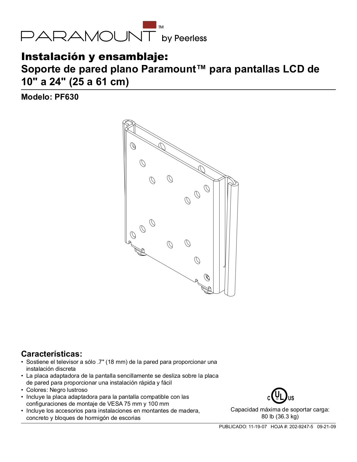
PF630
3
PF632
PF640
4
PF650
4
PF660
4
PF-80
PFL635
PFT640
3
PFT660
2
Pico Broadcaster HDS-PB100
Pinnacle
3
Pinnacle PI-140
2
Pinnacle PI-199
2
Pinnacle PI-399
Pinnacle PI-80
2
Pinnacle PI-T50
Pinnacle PI-T80
Pinnacle PO-70
Pinnacle PO-70A
Pinnacle PO-84
Pinnacle PO-84A
PJF2
PJF2-1
PJF2-1-S
2
PJF2-UNV
3
PJF2-UNV-S
5
PJF3-EXA
2
PJF3-EXA-W
PJF3-EXB
2
PJF3-EXC
2
PJF3-UNV
2
PJR125-EUK
PJR125-POR
PJR250
2
PJRL411
PLA50
2
PLA50-UNL
2
PLA50-UNLP
3
PLA50-UNLP-GB
3
PLA 50-UNLP-S
PLA 50-UNL-S
PLA60
2
PLA 60-S
2
PLA60-UNL
PLA60-UNLP
3
PLA60-UNLP-GB
PLA60-UNLP-GS
PLA60-UNLP-S
PLA60-UNL-S
PLAV 60
3
PLAV 60-S
2
Loading...
Loading...
Nothing found
PF630
Datasheet
2 pgs
245.12 Kb
0
User Manual
24 pgs
3.55 Mb
0
User Manual
2 pgs
167.75 Kb
0
Table of contents
Loading...
Peerless Industries PF630 User Manual
...
Peerless Industries User Manual
Download
Specifications and Main Features
Frequently Asked Questions
User Manual
Download
Loading...
+
hidden pages
Unhide
You need points to download manuals.
1 point = 1 manual.
You can buy points or you can get point for every manual you upload.
Buy points
Upload your manuals