

PEERLESS PF-50, PF-80, PF-110, PF-140, PF-210 Installation, Operation & Maintenance Manual
...Page 1
PUREFIRE
®
REV
2
Boilers
PF-50 PF-80 PF-110 PF-140 PF-210 PF-399
Gas
Installation,
Operation &
Maintenance
Manual
As an ENERGY STAR®Partner, PB Heat, LLC has determined that
this product meets the ENERGY STAR guidelines for energy efficiency.
®
Page 2

USING THIS MANUAL 1
A. INSTALLATION SEQUENCE . . . . . . . . . . . . . .1
B. SPECIAL ATTENTION BOXES . . . . . . . . . . . . .1
1. PREINSTALLATION 2
A. GENERAL . . . . . . . . . . . . . . . . . . . . . . . . . . . . .2
B. CODES & REGULATIONS . . . . . . . . . . . . . . . .2
C. ACCESSIBILITY CLEARANCES . . . . . . . . . . . .3
D. COMBUSTION & VENTILATION AIR . . . . . . . .4
E. PLANNING THE LAYOUT . . . . . . . . . . . . . . . .6
2. BOILER SET-UP 8
A. GENERAL . . . . . . . . . . . . . . . . . . . . . . . . . . . . .8
B. WALL MOUNTING . . . . . . . . . . . . . . . . . . . . . .8
C. FLOOR STANDING INSTALLATION . . . . . . . . .8
3. VENTING & AIR INLET PIPING 9
A. GENERAL . . . . . . . . . . . . . . . . . . . . . . . . . . . . .9
B. APPROVED MATERIALS . . . . . . . . . . . . . . . . .9
C. EXHAUST VENT/AIR INTAKE
PIPE LOCATION . . . . . . . . . . . . . . . . . . . . . . . .9
D. EXHAUST VENT/AIR INTAKE PIPE SIZING . .13
E. EXHAUST VENT/AIR INTAKE PIPE
INSTALLATION . . . . . . . . . . . . . . . . . . . . . . . .13
F. EXHAUST TAPPING FOR VENT SAMPLE . .14
G. BOILER REMOVAL FROM COMMON
VENTING SYSTEM . . . . . . . . . . . . . . . . . . . .14
4. WATER PIPING AND CONTROLS 15
A. GENERAL . . . . . . . . . . . . . . . . . . . . . . . . . . . .15
B. OPERATING PARAMETERS . . . . . . . . . . . . . .15
C. SYSTEM COMPONENTS . . . . . . . . . . . . . . . .15
D. SYSTEM PIPING . . . . . . . . . . . . . . . . . . . . . .19
E. FREEZE PROTECTION . . . . . . . . . . . . . . . . . .19
F. SPECIAL APPLICATIONS . . . . . . . . . . . . . . . .25
5. FUEL PIPING 26
A. GENERAL . . . . . . . . . . . . . . . . . . . . . . . . . . . .26
B. FUEL LINE SIZING . . . . . . . . . . . . . . . . . . . . .26
C. GAS SUPPLY PIPING – INSTALLATION . . . .26
D. GAS SUPPLY PIPING – OPERATION . . . . . . .27
E. MAIN GAS VALVE – OPERATION . . . . . . . . .28
6. CONDENSATE DRAIN PIPING 29
A. GENERAL . . . . . . . . . . . . . . . . . . . . . . . . . . . .29
B. CONDENSATE SYSTEM . . . . . . . . . . . . . . . .29
C. CONDENSATE DRAIN PIPE MATERIAL . . . .30
D. CONDENSATE DRAIN PIPE SIZING . . . . . . .30
E. CONDENSATE DRAIN PIPE
INSTALLATION . . . . . . . . . . . . . . . . . . . . . . . .30
7. ELECTRICAL CONNECTIONS 31
A. GENERAL . . . . . . . . . . . . . . . . . . . . . . . . . . .31
B. CUSTOMER CONNECTIONS . . . . . . . . . . . . .31
C. ZONE CIRCULATOR WIRING . . . . . . . . . . . . .32
D. INTERNAL WIRING . . . . . . . . . . . . . . . . . . . .32
8. BOILER CONTROL: INTERNAL
WIRING & OPERATION 36
A. CONTROL OVERVIEW . . . . . . . . . . . . . . . . . .36
B. IGNITION SEQUENCE . . . . . . . . . . . . . . . . . .38
C. BOILER CONTROL . . . . . . . . . . . . . . . . . . . . .40
D. CENTRAL HEATING . . . . . . . . . . . . . . . . . . . .42
E. DOMESTIC HOT WATER (DHW) . . . . . . . . . .45
F. SERVICE NOTIFICATION . . . . . . . . . . . . . . . .46
G. SYSTEM TEST . . . . . . . . . . . . . . . . . . . . . . . .47
H. STATUS & FAULT HISTORY . . . . . . . . . . . . . .47
I. SENSOR RESISTANCE . . . . . . . . . . . . . . . . .48
J. MULTIPLE BOILERS . . . . . . . . . . . . . . . . . . . .48
K. DEFAULTS . . . . . . . . . . . . . . . . . . . . . . . . . . .53
9. START-UP PROCEDURE 54
A. GENERAL . . . . . . . . . . . . . . . . . . . . . . . . . . . .54
B. CHECK WATER PIPING . . . . . . . . . . . . . . . . .54
C. CHECK GAS PIPING . . . . . . . . . . . . . . . . . . . .54
D. CHECK OPERATION . . . . . . . . . . . . . . . . . . . .54
E. LIGHTING & OPERATING PROCEDURES . . .56
10. TROUBLESHOOTING 57
A. BLOCKING ERRORS . . . . . . . . . . . . . . . . . . . .57
B. LOCKING ERRORS . . . . . . . . . . . . . . . . . . . . .57
C. ERROR MESSAGES IN A CASCADE
SYSTEM . . . . . . . . . . . . . . . . . . . . . . . . . . . . .57
D. WARNING ERRORS . . . . . . . . . . . . . . . . . . . .61
11. MAINTENANCE 63
A. GENERAL (WITH BOILER IN USE) . . . . . . . .64
B. WEEKLY (WITH BOILER IN USE) . . . . . . . . .64
C. ANNUALLY (BEFORE START OF HEATING
SEASON) . . . . . . . . . . . . . . . . . . . . . . . . . . . .64
D. CONDENSATE CLEANING
INSTRUCTIONS . . . . . . . . . . . . . . . . . . . . . . .64
E. COMBUSTION CHAMBER COIL CLEANING
INSTRUCTIONS . . . . . . . . . . . . . . . . . . . . . . .65
12. BOILER DIMENSIONS & RATINGS 66
13. REPAIR PARTS 70
APPENDIX A. STATUS SCREENS 78
APPENDIX B. USER MENU 82
APPENDIX C. INSTALLER MENU 83
APPENDIX D. COMBUSTION TEST
RECORD 88
TABLE OF CONTENTS
TABLE OF CONTENTS
Page 3
A. INSTALLATION SEQUENCE
Follow the installation instructions provided in this manual
in the order shown. The order of these instructions has
been set in order to provide the installer with a logical
sequence of steps that will minimize potential
interferences and maximize safety during boiler
installation.
B. SPECIAL ATTENTION BOXES
Throughout this manual special attention boxes are
provided to supplement the instructions and make special
notice of potential hazards. The definition of each of
these categories, in the judgement of PB Heat, LLC
are as follows:
USING THIS MANUAL
Indicates special attention is needed, but not directly
related to potential personal injury or property
damage.
NOTICE
Indicates a condition or hazard which will or can
cause minor personal injury or property damage.
CAUTION
DANGER
Indicates a condition or hazard which will cause
severe personal injury, death or major property
damage.
Indicates a condition or hazard which may cause
severe personal injury, death or major property
damage.
WARNING
1
USING THIS MANUAL
Page 4

A. GENERAL
1. PUREFIRE®boilers are supplied completely assembled
as packaged boilers. The package should be inspected
for damage upon receipt and any damage to the unit
should be reported to the shipping company and
wholesaler. This boiler should be stored in a clean, dry
area.
2. Carefully read these instructions and be sure to
understand the function of all connections prior to
beginning installation. Contact your PB Heat, LLC
Representative for help in answering questions.
3. This boiler must be installed by a qualified contractor.
The boiler warranty may be voided if the boiler is not
installed correctly.
4. A hot water boiler installed above radiation or as
required by the Authority having jurisdiction, must be
provided with a low water fuel cut-off device either as
part of the boiler or at the time of installation.
B. CODES & REGULATIONS
1. Installation and repairs are to be performed in strict
accordance with the requirements of state and local
regulating agencies and codes dealing with boiler and
gas appliance installation.
2. In the absence of local requirements the following
should be followed:
a. ASME Boiler and Pressure Vessel Code, Section
IV - “Heating Boilers”
b. ASME Boiler and Pressure Vessel Code, Section
VI - “Recommended Rules for the Care and
Operation of Heating Boilers”
c. ANSI Z223.1/NFPA 54 - “National Fuel Gas Code”
d. ANSI/NFPA 70 - “National Electrical Code”
e. ANSI/NFPA 211 - “Chimneys, Fireplaces, Vents
and Solid Fuel Burning Appliances”
3. Where required by the authority having jurisdiction,
the installation must conform to the Standard for
Controls and Safety Devices for Automatically Fired
Boilers, ANSI/ASME CSD-1.
**Please read if installing in Massachusetts**
Massachusetts requires manufacturers of Side Wall
Vented boilers to provide the following information
from the Massachusetts code:
·
A hard wired carbon monoxide detector with an
alarm and battery back-up must be installed on
the floor level where the gas equipment is to be
installed AND on each additional level of the
dwelling, building or structure served by the side
wall horizontal vented gas fueled equipment.
·
In the event that the side wall horizontally vented
gas fueled equipment is installed in a crawl space
or an attic, the hard wired carbon monoxide
detector with alarm and battery back-up may be
installed on the next adjacent floor level.
·
Detector(s) must be installed by qualified licensed
professionals.
·
APPROVED CARBON MONOXIDE
DETECTORS: Each carbon monoxide detector
shall comply with NFPA 720 and be ANSI/UL
2034 listed and IAS certified.
·
SIGNAGE: A metal or plastic identification plate
shall be permanently mounted to the exterior of
the building at a minimum height of eight (8) feet
above grade directly in line with the exhaust vent
terminal for the horizontally vented gas fueled
heating appliance or equipment. The sign shall
read, in print size no less than one-half (1/2) inch
in size, “GAS VENT DIRECTLY BELOW.
KEEP CLEAR OF ALL OBSTRUCTIONS”.
·
EXEMPTIONS to the requirements listed above:
°
The above requirements do not apply if the
exhaust vent termination is seven (7) feet or
more above finished grade in the area of the
venting, including but not limited to decks and
porches.
°
The above requirements do not apply to a
boiler installed in a room or structure separate
from the dwelling, building or structure used in
whole or in part for residential purposes.
·
This boiler installation manual shall remain with
the boiler at the completion of the installation.
See the latest edition of Massachusetts Code 248 CMR
for complete verbage and also for additional (non-vent
related) requirements (248 CMR is available online).
If your installation is NOT in Massachusetts, please
see your authority of jurisdiction for requirements that
may be in effect in your area. In the absence of such
requirements, follow the National Fuel Gas Code,
ANSI Z223.1/NFPA 54 and/or CAN/CSA B149.1,
Natural Gas and Propane Installation Code.
2
PREINSTALLATION
1. PREINSTALLATION
Liquefied Petroleum (LP) Gas or Propane is heavier
than air and, in the event of a leak, may collect in low
areas such as basements or floor drains. The gas
may then ignite resulting in a fire or explosion.
WARNING
Page 5
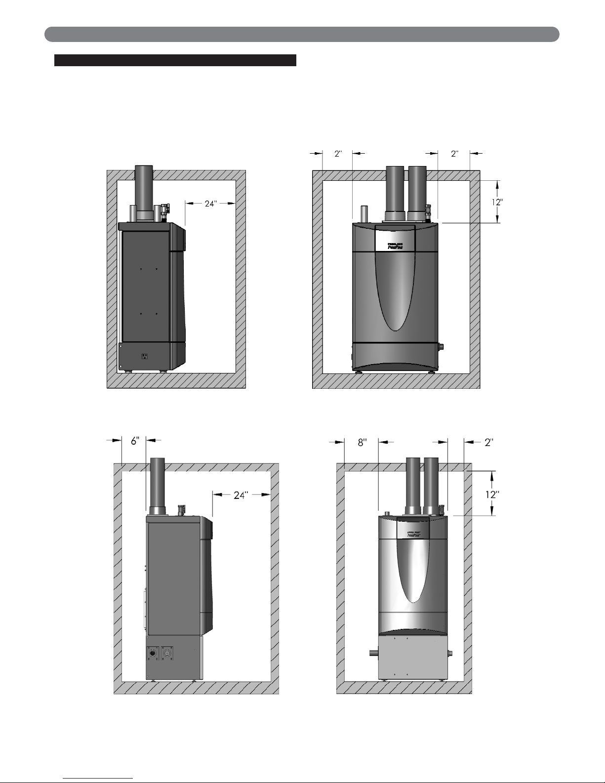
C. ACCESSIBILITY CLEARANCES
1. The PUREFIRE®boiler is certified for closet installations
with zero clearance to combustible construction. In
addition, it is design certified for use on combustible
floors.
2. Figure 1.1 shows the minimum recommended
clearances to allow reasonable access to the boiler for
Models PF-50, PF-80, PF-110 and PF-140. For
Models PF-210 & PF-399, Figure 1.2 shows the
minimum recommended accessibility clearances.
However, Local codes or special conditions may
require greater clearances.
E. D.
COMBUSTION AND VENTILATION AIR
3
PREINSTALLATION
Figure 1.1: Minimum Accessibility Clearances – PF-50, PF-80, PF-110 & PF-140
Figure 1.2: Minimum Accessibility Clearances – PF-210 & PF-399
Page 6
D. COMBUSTION AND VENTILATION AIR
1. The PUREFIRE®boiler is designed for operation with
combustion air piped directly to the boiler from
outside the building (sealed combustion). If the boiler
is vented vertically, the combustion air can be
supplied from within the building only if adequate
combustion air and ventilation air is provided in
accordance with the section of the National Fuel Gas
Code entitled, "Air for Combustion and Ventilation" or
applicable provisions of the local building code.
Subsections 3 through 10 as follows are based on the
National Fuel Gas Code requirements.
2. If the combustion air is piped directly to the boiler
from outside the building, no additional combustion
or ventilation air is required. Otherwise, follow the
National Fuel Gas Code recommendations
summarized in subsections 3 through 10.
3. Required Combustion Air Volume: The total required
volume of indoor air is to be the sum of the required
volumes for all appliances located within the space.
Rooms communicating directly with the space in
which the appliances are installed and through
combustion air openings sized as indicated in
Subsection 3 are considered part of the required
volume. The required volume of indoor air is to be
determined by one of two methods.
a. Standard Method
: The minimum required volume
of indoor air (room volume) shall be 50 cubic feet
per 1000 BTU/Hr (4.8 m3/kW). This method is to
be used if the air infiltration rate is unknown or if
the rate of air infiltration is known to be greater
than 0.6 air changes per hour. As an option, this
method may be used if the air infiltration rate is
known to be between 0.6 and 0.4 air changes per
hour. If the air infiltration rate is known to be
below 0.4 then the Known Air Infiltration Rate
Method must be used. If the building in which this
appliance is to be installed is unusually tight, PB
Heat recommends that the air infiltration rate be
determined.
b. Known Air Infiltration Rate Method
:
where:
I
fan
= Input of the fan assisted appliances
assisted in Btu/hr
ACH = air change per hour (percent of the
volume of the space exchanged per
hour, expressed as a decimal)
Note: These calculations are not to be used for
infiltration rates greater than 0.60 ACH.
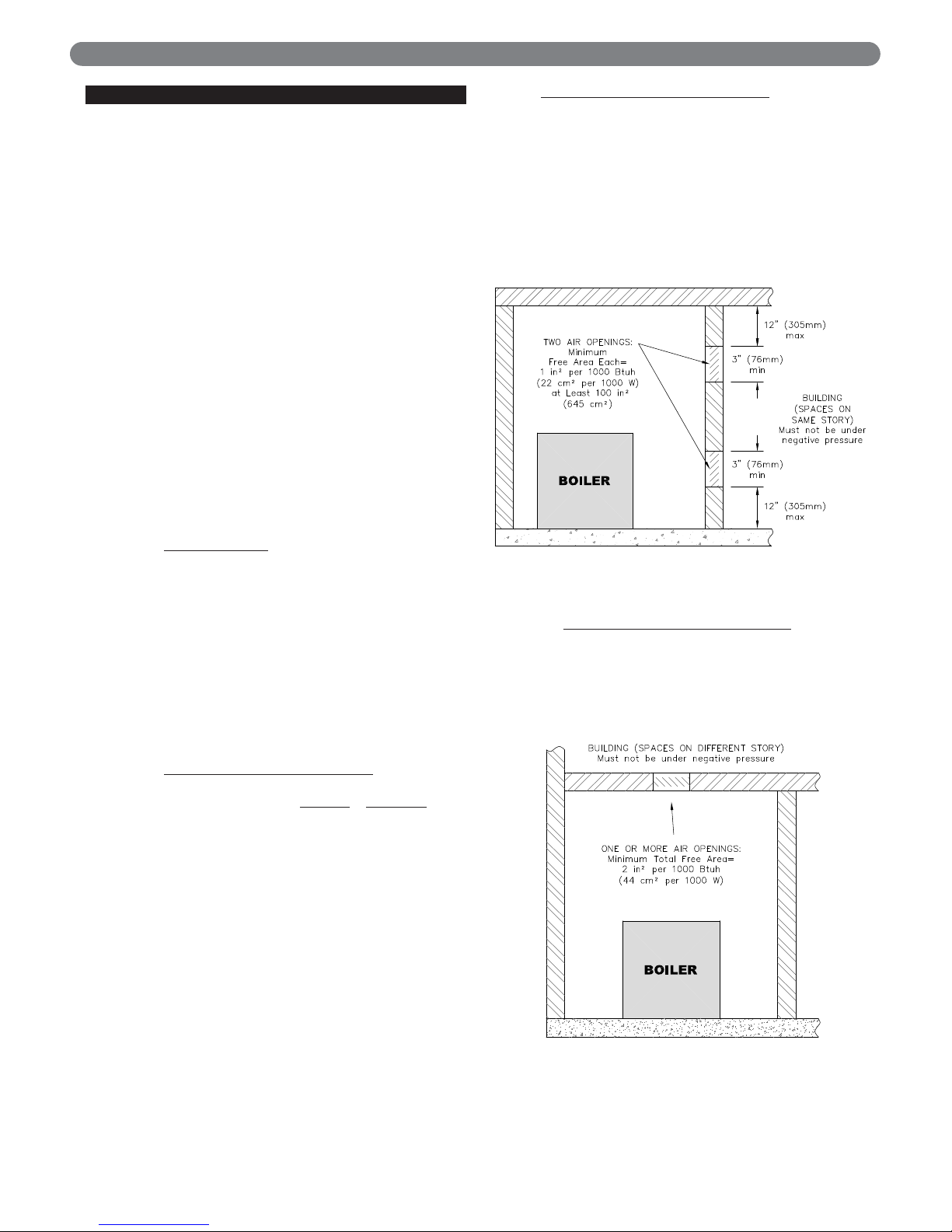
4. Indoor Air Opening Size and Location: Openings
connecting indoor spaces shall be sized and located as
follows:
a. Combining Spaces on the Same Floor
: Provide two
permanent openings communicating with additional
spaces that have a minimum free area of 1 in
2
per
1000 Btu/hr (22 cm2per 1000 W) of the total input
rating of all gas fired equipment but not less than 100
in
2
(645 cm2). One opening is to begin within 12
inches (305 mm) from the top of the space and the
other is to begin within 12 inches (305 mm) from the
floor. The minimum dimension of either of these
openings shall be 3 inches (76 mm). See Figure 1.3
for an illustration of this arrangement.
b. Combining Spaces on Different Floors
: Provide
one or more permanent openings communicating
with additional spaces that have a total minimum
free area of 2 in
2
per 1000 Btu/hr (44 cm2per
1000 W) of total input rating of all equipment. See
Figure 1.4 for an illustration of this arrangement.
4
15 ft
3
I
fan
ACH 1000
Btu
/
hr
Required Volume
fan
=
⎛
⎜
⎝
⎛
⎜
⎝
Figure 1.3: Air Openings – All Air from Indoors
on the Same Floor
Figure 1.4: Air Openings – All Air from Indoors
on Different Floors
PREINSTALLATION
Page 7
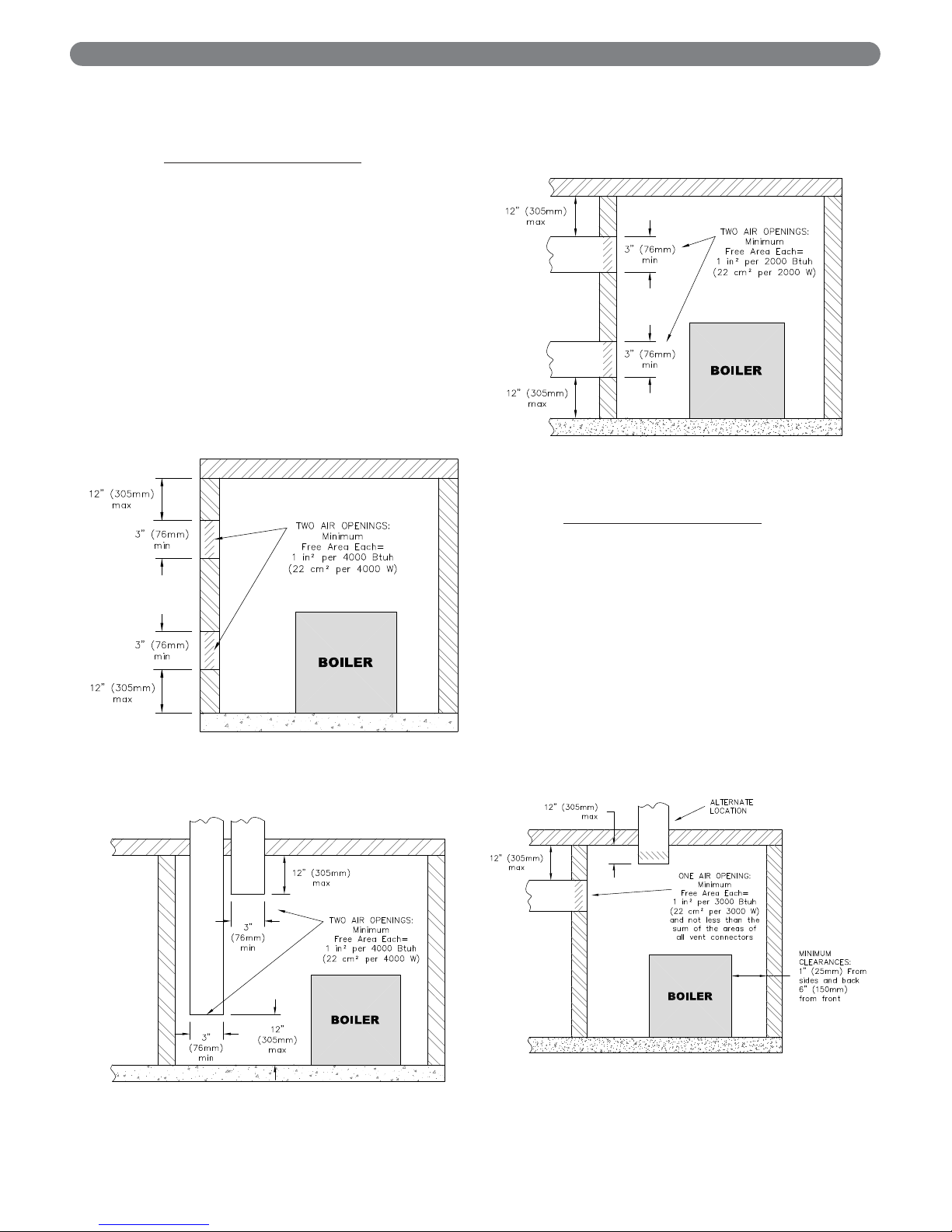
5. Outdoor Combustion Air: Outdoor combustion air is
to be provided through one or two permanent
openings. The minimum dimension of these air
openings is 3 inches (76 mm).
a. Two Permanent Opening Method
: Provide two
permanent openings. One opening is to begin
within 12 inches (305 mm) of the top of the space
and the other is to begin within 12 inches (305
mm) of the floor. The openings are to
communicate directly or by ducts with the
outdoors or with spaces that freely communicate
with the outdoors. The size of the openings shall
be determined as follows:
i. Where communicating directly or through
vertical ducts with the outdoors each opening
shall have a minimum free area of 1 in2 per
4000 Btu/hr (22 cm
2
per 4000 W) of total
input rating for all equipment in the space. See
Figure 1.5 for openings directly
communicating with the outdoors or Figure
1.6 for openings connected by ducts to the
outdoors.
ii. Where communicating with the outdoors through
horizontal ducts, each opening shall have a
minimum free area of 1 in
2
per 2000 Btu/hr (22
cm2per 2000 W) of total rated input for all
appliances in the space. See Figure 1.7.
b. One Permanent Opening Method
: Provide one
permanent opening beginning within 12 inches
(305 mm) of the top of the space. The opening
shall communicate directly with the outdoors,
communicate through a vertical or horizontal duct,
or communicate with a space that freely
communicates with the outdoors. The opening
shall have a minimum free area of 1 in
2
per 3000
Btu/hr of total rated input for all appliances in the
space and not less than the sum of the crosssectional areas of all vent connectors in the space.
The gas-fired equipment shall have clearances of
at least 1 inch (25 mm) from the sides and back
and 6 inches (150 mm) from the front of the
appliance. See Figure 1.8 for this arrangement.
5
Figure 1.5: Air Openings – All Air Directly from
Outdoors
Figure 1.6: Air Openings – All Air from Outdoors
through Vertical Ducts
Figure 1.7: Air Openings – All Air from Outdoors
through Horizontal Ducts
Figure 1.8: Air Openings – All Air from Outdoors
through One Opening
PREINSTALLATION
Page 8

6. Combination Indoor and Outdoor Combustion Air: If
the required volume of indoor air exceeds the
available indoor air volume, outdoor air openings or
ducts may be used to supplement the available indoor
air provided:
a. The size and location of the indoor openings
comply with Subsection 3.
b. The outdoor openings are to be located in
accordance with Subsection 4.
c. The size of the outdoor openings are to be sized
as follows:
where:
A
req
= minimum area of outdoor openings.
A
full
= full size of outdoor openings calculated
in accordance with Subsection 4.
V
avail
= available indoor air volume
V
req
= required indoor air volume
7. Engineered Installations: Engineered combustion air
installations shall provide an adequate supply of
combustion, ventilation, and dilution air and shall be
approved by the authority having jurisdiction.
8. Mechanical Combustion Air Supply:
a. In installations where all combustion air is
provided by a mechanical air supply system, the
combustion air shall be supplied from the
outdoors at the minimum rate of 0.35 ft
3
/min per
1000 Btu/hr (0.034 m
3
/min per 1000 W) of the
total rated input of all appliances in the space.
b. In installations where exhaust fans are installed,
additional air shall be provided to replace the
exhaust air.
c. Each of the appliances served shall be interlocked
to the mechanical air supply to prevent main
burner operation when the mechanical air supply
system is not in operation.
d. In buildings where the combustion air is provided
by the mechanical ventilation system, the system
shall provide the specified combustion air rate in
addition to the required ventilation air.
9. Louvers & Grills:
a. The required size of openings for combustion,
ventilation, and dilution air shall be based on the
net free area of each opening.
i. Where the free area through a louver or grille
is known, it shall be used in calculating the
opening size required to provide the free area
specified.
ii. Where the free area through a louver or grille
is not known, it shall be assumed that wooden
louvers will have 25% free area and metal
louvers and grilles will have 75% free area.
iii. Non-motorized dampers shall be fixed in the
open position.
b. Motorized dampers shall be interlocked with the
equipment so that they are proven in the full open
position prior to ignition and during operation of
the main burner.
i. The interlock shall prevent the main burner
from igniting if the damper fails to open during
burner startup.
ii. The interlock shall shut down the burner if the
damper closes during burner operation.
10. Combustion Air Ducts:
a. Ducts shall be constructed of galvanized steel or
an equivalent corrosion- resistant material.
b. Ducts shall terminate in an unobstructed space,
allowing free movement of combustion air to the
appliances.
c. Ducts shall serve a single space.
d. Ducts shall not serve both upper and lower
combustion air openings where both such
openings are used. The separation between ducts
serving upper and lower combustion air openings
shall be maintained to the source of combustion
air.
e. Ducts shall not be screened where terminating in
an attic space.
f. Horizontal upper combustion air ducts shall not
slope downward toward the source of the
combustion air.
g. The remaining space surrounding a chimney liner,
gas vent, special gas vent, or plastic piping
installed within a masonry, metal, or factory built
chimney shall not be used to supply combustion
air unless it is directly piped to the air inlet as
shown in Figure 3.9.
h. Combustion air intake openings located on the
exterior of buildings shall have the lowest side of
the combustion air intake opening at least 12
inches (305 mm) above grade.
11. Refer to Section 3 of this manual, Venting & Air Inlet
Piping, for specific instructions for piping the exhaust
and combustion air.
E. PLANNING THE LAYOUT
1. Prepare sketches and notes showing the layout of the
boiler installation to minimize the possibility of
interferences with new or existing equipment, piping,
venting and wiring.
2. The following sections of this manual should be
reviewed for consideration of limitations with
respect to:
a. Venting and Air Inlet Piping: Section 3
b. Water Piping: Section 4
c. Fuel Piping: Section 5
d. Condensate Removal: Section 6
e. Electrical Connections: Section 7
f. Boiler Control: Section 8
g. Boiler Dimensions and Ratings: Section 12
6
PREINSTALLATION
Page 9
7
Do not install this boiler where gasoline or other
flammable liquids or vapors are stored or are in use.
WARNING
This boiler is certified as an indoor appliance. Do not
install this boiler outdoors or locate where it will be
exposed to freezing temperatures.
WARNING
Do not install this boiler in the attic.
WARNING
PREINSTALLATION
Page 10
8
A. GENERAL
1. PUREFIRE®boilers are intended for installation in an
area with a floor drain or in a suitable drain pan. Do
not install any boiler where leaks or relief valve
discharge will cause property damage.
2. The P
UREFIRE
®
boiler is not intended to support
external piping. All venting and other piping should
be supported independently of the boiler.
3. Install the boiler level to prevent condensate from
backing up inside the boiler.
4. P
UREFIRE
®
boilers can be wall mounted or floor
standing. The following instructions provide guidance
for both configurations.
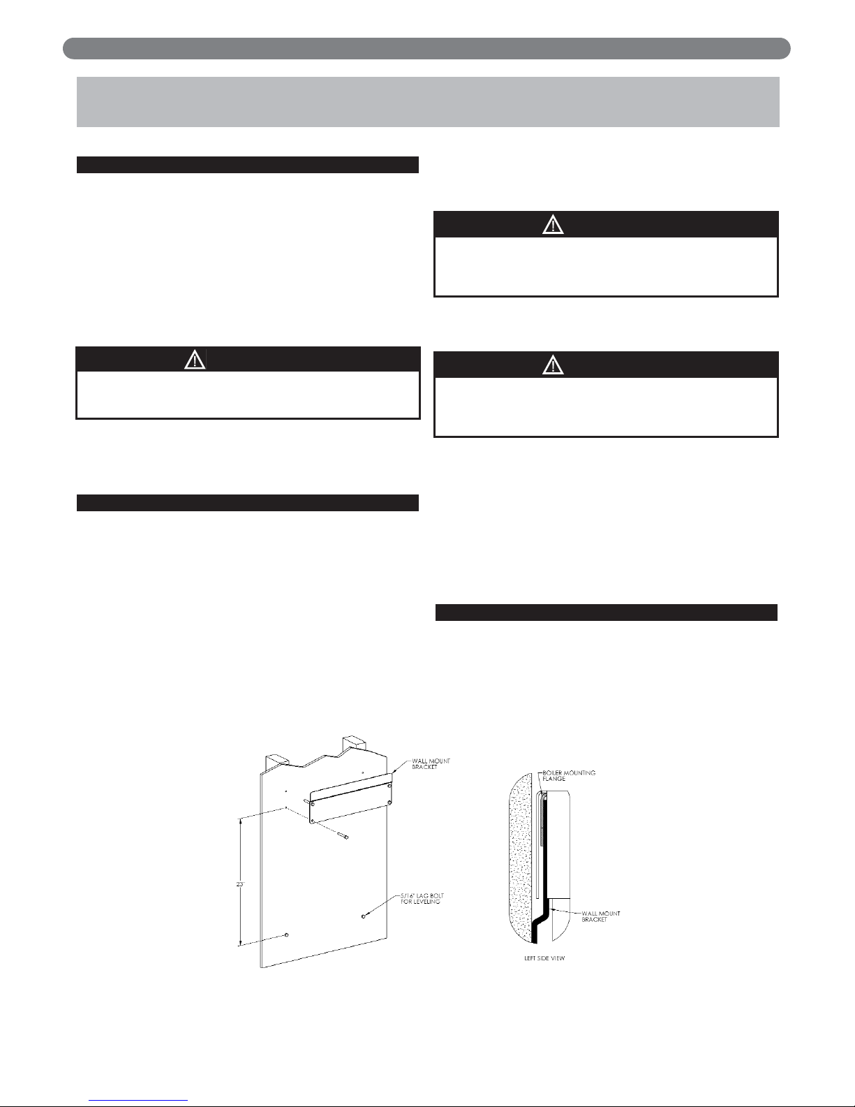
B. WALL MOUNTING
1. Models PF-50, PF-80, PF-110 and PF-140:
a. An optional wall mounting bracket kit (54171) is
available for wall mounting these sizes.
b. Mount the bracket level on the wall using 5/16" lag
bolts. Be sure the lag bolts are fully supported by
wall studs or adequate wall structure.
c. The mounting bracket has (4) holes on 16" centers
as shown in Figure 2.1. This is intended to give
installers the ability to mount the bracket on two
wall studs spaced at this interval. If existing wall
studs are spaced differently or if the desired
location is not in line with the wall studs,
additional support is required.
d. If the boiler is wall mounted using the optional
wall bracket, be sure that the wall provides
adequate support for the boiler.
e. Be sure to adequately support the boiler while
installing external piping or other connections.
f. Be sure that condensate piping is routed to a
suitable drain or condensate pump.
2. All Models can be wall mounted by using the optional
stand (91400).
a. Use the leveling feet provided with the boiler to
assure proper level.
b. Be sure to leave adequate provisions for
condensate piping and/or a pump (if required).
C. FLOOR STANDING INSTALLATION
1. For floor standing installations, use the leveling feet to
assure that the boiler is completely level. This will
prevent condensate from backing up in the boiler.
2. Be sure to leave adequate space for condensate
piping or a pump if required.
BOILER SET-UP
2. BOILER SET-UP
The wall mounting bracket is designed to support the
boiler. External piping for water, venting, air intake
and fuel supply is to be supported separately
WARNING
Figure 2.1: Optional Wall Mounting Bracket for PF-50, PF-80, PF-110 and PF-140 Boilers
This boiler must be installed level to prevent
condensate from backing up inside the boiler.
CAUTION
Make sure the boiler wall bracket is adequately
supported. Do not install this bracket on dry wall
unless adequately supported by wall studs.
WARNING
Page 11
9
A. GENERAL
1. Install the PUREFIRE®boiler venting system in accordance
with these instructions and with the National Fuel Gas
Code, ANSI Z223.1/NFPA 54, CAN/CGA B149, and/or
applicable provisions of local building codes.
2. The P
UREFIRE
®
boiler is a direct vent appliance and is
ETL Listed as a Category IV appliance with Intertek
Testing Laboratories, Inc.
B. APPROVED MATERIALS
1. Table 3.1 lists approved materials for vent pipe (and
adhesives where applicable). Use only these materials
for exhaust vent piping.
2. PVC pipe and fittings are not to be used for venting in
confined spaces such as closet installations. Use only
CPVC or Mugro™ vent pipe under these conditions.
3. Cellular core piping is approved for inlet air piping only.
* PVC pipe/fittings are not to be used for venting within
confined spaces.
Notice: Installations in Canada require compliance with
ULC S636 Standard for Type BH Gas Venting Systems.
C. EXHAUST VENT/AIR INTAKE PIPE
LOCATION
1. Install vent piping before installing water, fuel, or
condensate piping. Working from largest to smallest
diameter reduces the complexity of piping
interferences.
2. Vent and air intake piping is to be installed so that
there is sufficient access for routine inspection as
required in Section 11, of this manual.
3. The vent piping for this boiler is approved for zero
clearance to combustible construction. However, a fire
stop must be used where the vent pipe penetrates
walls or ceilings.
4. The Peerless
®
PUREFIRE®boiler, like all high efficiency,
gas-fired appliances, is likely to produce a vapor
plume due to condensation. Surfaces near the vent
termination will likely become coated with
condensation.
5. The maximum combined vent and air inlet vent
length for the Peerless
®
PUREFIRE®boiler is about 200
equivalent feet (60 m).Be sure that the boiler is
located such that the maximum vent length is not
exceeded.
6. Air Intake Pipe Location – Sidewall Venting:
a. Provide 1 foot (30 cm) clearance from the bottom
of the air intake pipe to the level of maximum
snow accumulation. Snow removal may be
necessary to maintain clearances.
b. Do not locate air intake pipe in a parking area
where machinery may damage the pipe.
c. The maximum distance between the air intake
and exhaust is 6 feet (1.8 m).
VENTING & AIR INLET PIPING
3. VENTING & AIR INLET PIPING
The venting system for this product is to be installed in
strict accordance with these venting instructions.
Failure to install the vent system properly may result in
severe personal injury, death or major property damage.
WARNING
This vent system operates under positive pressure.
Vent connectors serving appliances vented by
natural draft shall not be connected into any portion
of this venting system. Failure to comply may result
in serious injury, death or major property damage.
WARNING
Only the materials listed below are approved for use
with the
P
UREFIRE
®
boiler. Use only these components
in accordance with these instructions. Failure to use
the correct material may result in serious injury,
death, or major property damage.
WARNING
Table 3.1: Approved Materials for Exhaust Vent Pipe
Use of cellular core pipe for any exhaust vent
component is prohibited. Use of cellular core pipe
may result in severe personal injury, death, or major
property damage.
WARNING
If the maximum equivalent vent length is exceeded,
the maximum burner input rate may be reduced.
NOTICE
Locating air intake and exhaust pipes on different
sides of a building can cause erratic operation due to
wind gusts. When using the sidewall venting
configuration always locate both terminations on the
same outside wall.
NOTICE
Description Material
Conforming to
Standard
Vent Piping & Fittings
PVC (Sch 40 or 80)*
ANSI/ASTM D1785
CPVC (Sch 40 or 80) ANSI/ASTM D1785
PVC-DWV*
ANSI/ASTM D2665
MUGRO™ PP(s) ULC S636
Pipe Cement
(PVC & CPVC Only)
PVC/CPVC Cement ANSI/ASTM D2564
Page 12
d. If the vent pipe and air inlet pipe terminations
penetrate the wall at the same level the minimum
distance between them is 8" center-to-center.
e. For multiple boiler installations, the minimum
horizontal distance between the inlet of one boiler
to the exhaust of an adjacent boiler is 8" center-tocenter. In addition, the minimum vertical distance
between the exhaust and air inlet is 6". See Figure
3.1 for an illustration.
f. The exhaust outlet of the vent pipe should not be
angled any more than 5º from horizontal.
g. Precautions should be taken to prevent
recirculation of flue gases to the air inlet pipe of
the boiler or other adjacent appliances.
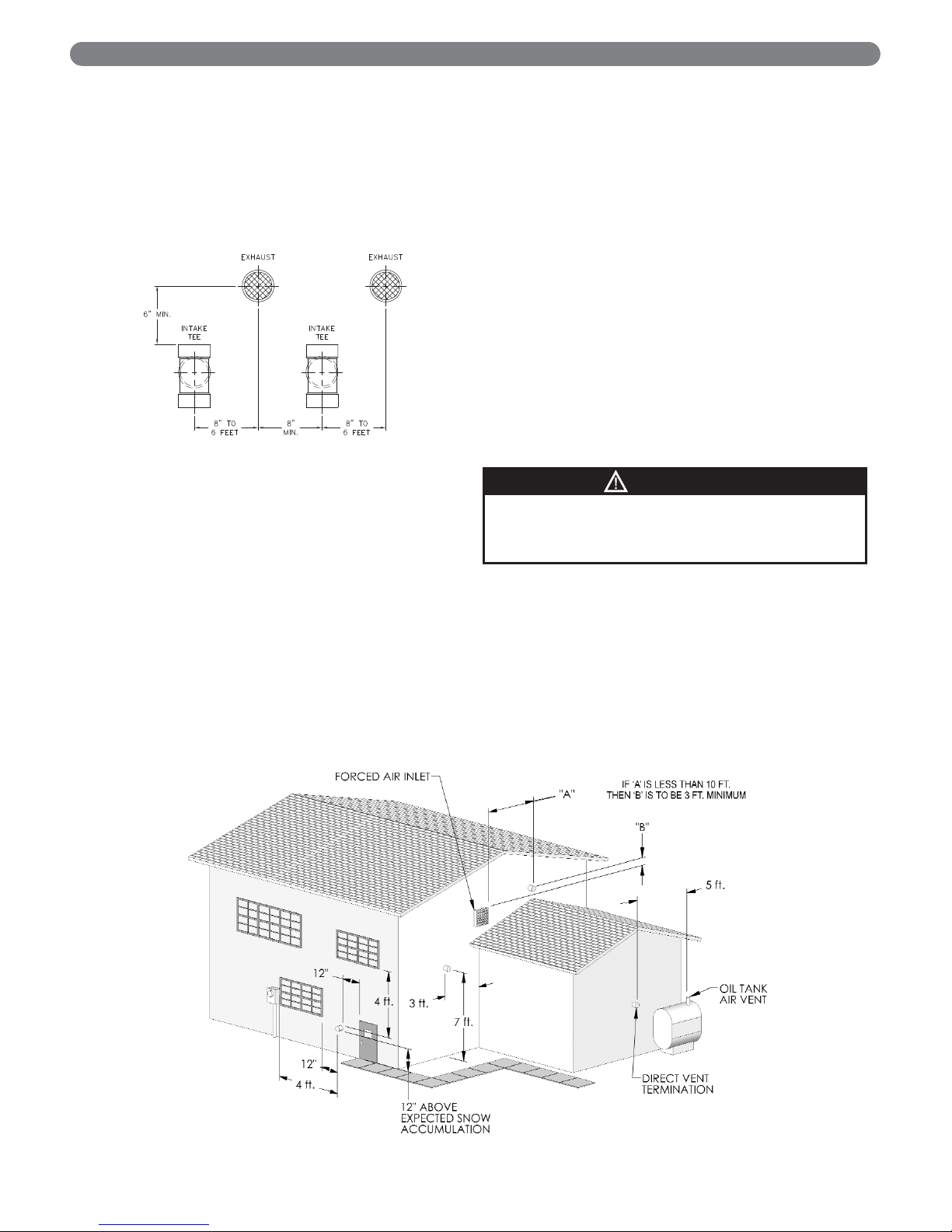
7. Sidewall Venting Configuration:
a. See Figure 3.2 for an illustration of clearances for
location of exit terminals of direct-vent venting
systems.
• This boiler vent system shall terminate at least
3 feet (0.9 m) above any forced air inlet
located within 10 ft (3 m). Note: This does not
apply to the combustion air intake of a directvent appliance.
• Provide a minimum of 1 foot (30 cm) distance
from any door, operable window, or gravity
intake into any building.
• Provide a minimum of 1 foot (30 cm) clearance
from the bottom of the exit terminal above the
expected snow accumulation level. Snow
removal may be required to maintain clearance.
• Provide a minimum of 4 feet (1.22 m)
horizontal clearance from electrical meters, gas
meters, gas regulators, and relief equipment. In
no case shall the exit terminal be above or
below the aforementioned equipment unless
the 4 foot horizontal distance is maintained.
• Do not locate the exhaust exit terminal over
public walkways where condensate could drip
and create a hazard or nuisance.
• When adjacent to public walkways, locate the
exit terminal at least 7 feet above grade.
• Do not locate the exhaust termination directly
under roof overhangs to prevent icicles from
forming or recirculation of exhaust gases from
occurring.
• Provide 3 feet clearance from the inside corner
of adjacent walls.
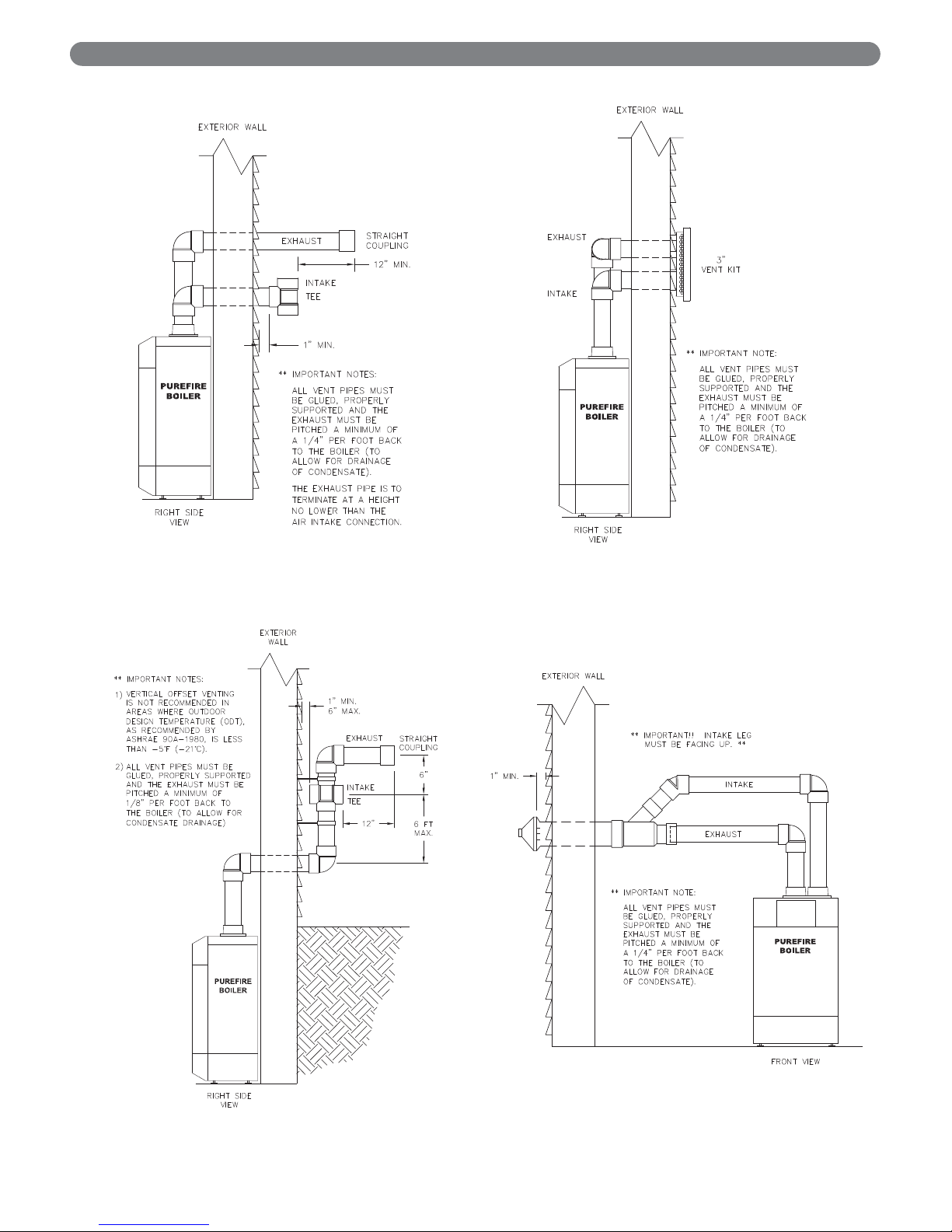
b. Figure 3.3 and 3.4 show approved sidewall venting
configurations using the standard fittings supplied.
c. Figure 3.4 is only approved for locations in which
the outdoor temperature is above -5°F (-21°C) in
accordance with ASHRAE 90A-1980
recommendations.
d. Figures 3.5 and 3.6 show approved sidewall vent
configurations using optional vent termination kits.
10
VENTING & AIR INLET PIPING
Figure 3.1: Vent Pipe Spacing for Multiple
P
UREFIRE
®
Boilers
Figure 3.2: Exit Terminal Location for Mechanical Draft and Direct-Vent Venting Systems
Condensing flue gases can freeze on exterior
building surfaces which may cause discoloration and
degradation of the surfaces.
CAUTION
Page 13
11
VENTING & AIR INLET PIPING
Figure 3.3: Standard Exhaust and Air Inlet Pipe
Penetrations
Figure 3.4: Offset Exhaust and Air Inlet
Terminations
Figure 3.5: Optional Stainless Steel Vent Kit
Installation
Figure 3.6: Optional Concentric PVC Vent Kit
Installation
Page 14
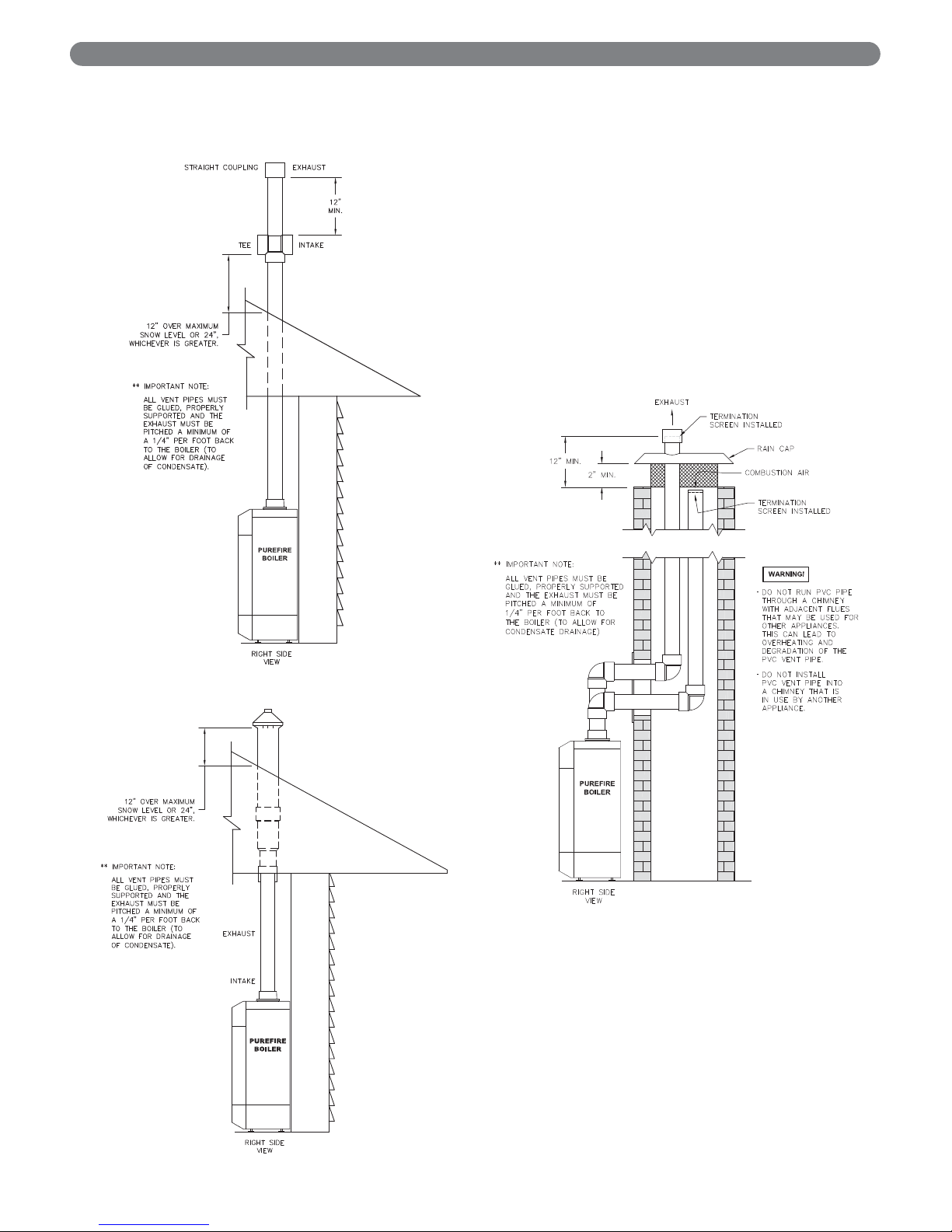
8. Vertical Venting Configuration:
a. Figure 3.7 shows the approved venting
configuration for vertical venting using the
standard fittings supplied.
b. Locate the air intake pipe inlet 12" above the
expected snow accumulation on the roof surface
or 24" above the roof surface, whichever is greater.
c. Locate the end of the exhaust vent pipe a minimum
of 12" above the inlet to the air intake pipe.
d. Figure 3.8 shows an approved vertical vent
configuration using the optional concentric vent
termination kit.
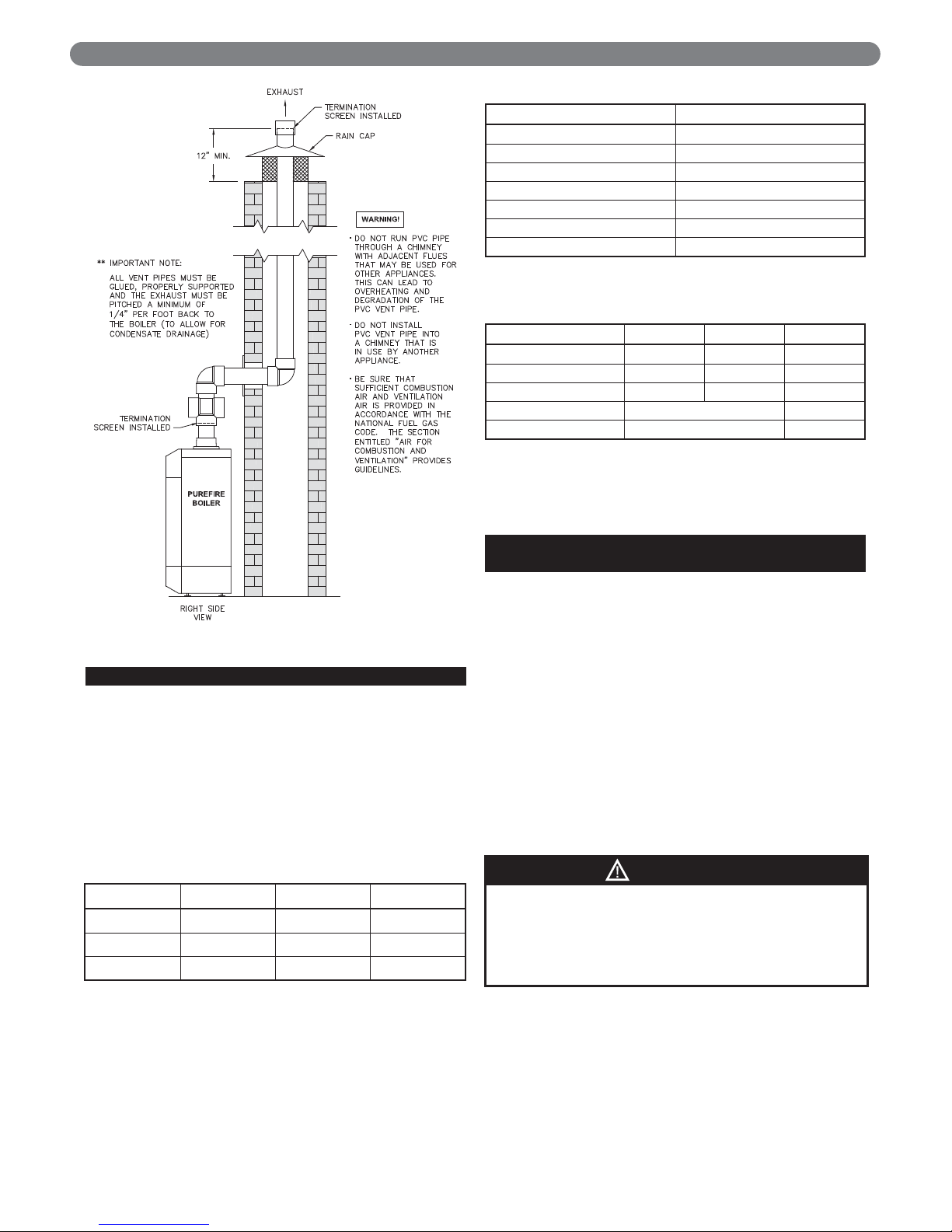
e. Figure 3.9 shows an option for routing the exhaust
and air inlet piping through an unused chimney.
f. Figure 3.10 shows an option for routing the
exhaust through an unused chimney with the
combustion air supplied from inside the building.
Be sure to note the requirements for combustion
air as listed under Section 1.D. "Combustion and
Ventilation Air". These requirements are in
accordance with the National Fuel Gas Code.
12
VENTING & AIR INLET PIPING
Figure 3.7: Standard Vertical Vent Installation
Figure 3.8: Concentric PVC Vertical Vent Installation
Figure 3.9
Page 15
13
D. EXHAUST VENT/AIR INTAKE PIPE SIZING
1. PUREFIRE®boiler models PF-50, PF-80, PF-110, PF-
140 and PF-210 are to be installed using 3" Schedule
40 or 80 PVC or CPVC piping using the provided
vent adapter. P
UREFIRE
®
model PF-399 boilers are to
be installed using 4" Schedule 40 or 80 PVC or CPVC
piping using the vent adapter provided.
2. Concentric polypropylene venting systems can be
installed using optional MUGRO™ vent adapters.
Table 3.2 shows the appropriate Stock Codes.
Contact your PB Heat, LLC Representative for more
information on this option.
3. The total combined length of exhaust vent and air
intake piping is 200 equivalent feet (60 m).
a. The equivalent length of elbows, tees and other
fittings are listed in Table 3.3.
b. The equivalent length can be calculated as follows.
This is well below the 200 feet maximum
equivalent length. If the total is above 200
equivalent feet, alternate boiler locations or
exhaust penetration location should be considered.
E. EXHAUST VENT/AIR INTAKE
INSTALLATION
1. Figures 12.1 & 12.2 show the exhaust connection on
top of the boiler, near the rear in the center.
a. The exhaust connection for PF-50, PF-80, PF- 110
and PF-140 boilers is a 3" CPVC Female Pipe
Adapter.
b. The exhaust connections for the PF-210 (3") and
PF-399 (4") are male CPVC pipe.
c. These connections are to be joined with suitable
PVC/CPVC adhesives in accordance with
manufacturers’ instructions.
2. The Air Intake connection is to the right of the exhaust.
3. Both connections are clearly marked.
4. Remove all burrs and debris from the joints and fittings.
5. Horizontal lengths of exhaust vent must be installed with
a slope of not less than 1/4" per foot (21mm per meter)
toward the boiler to allow condensate to drain from the
vent pipe. If the vent pipe must be piped around an
obstacle that causes a low point in the piping, a drain
with an appropriate trap must be installed.
VENTING & AIR INLET PIPING
This appliance uses a positive pressure venting
system. All joints must be sealed completely to
prevent leakage of flue products into living spaces.
Failure to do this may result in severe personal injury,
death or major property damage.
WARNING
Exhaust Air Inlet Total
Straight Length of Pipe 50' 50' 100'
90° Elbows, SR 2 x 5'= 10' 1 x 5' = 5' 15'
45° Elbows, SR 2 x 3' = 6' 6'
Conc. Vent Termination 1 x 3' = 3' 3'
Total 124'
Table 3.4: Sample Equivalent Length Calculation
Figure 3.10
Boiler Model Stock Code Boiler Model Stock Code
PF-50 54155 PF-140 54155
PF-80 54155 PF-210 54236
PF-110 54155 PF-399 54237
Table 3.2: Stock Codes
Fitting Description Equivalent Length
Elbow, 90° Short Radius 5 feet
Elbow, 90° Long Radius 4 feet
Elbow, 45° Short Radius 3 feet
Coupling 0 feet
Air Intake Tee 0 feet
Stainless Steel Vent Kit 1 foot
Concentric Vent Kit 3 feet
Table 3.3: Equivalent Length of Fittings
Page 16

6. All piping must be fully supported. Use pipe hangers
at a minimum of 4 foot (1.22 meter) intervals to
prevent sagging of the pipe.
7. Exhaust and air inlet piping is to be supported
separately and should not apply force to the boiler.
8. Penetration openings around the vent pipe and air
intake piping are to be fully sealed to prevent exhaust
gases from entering building structures.
9. PVC & CPVC Piping:
a. Use only solid PVC or CPVC Schedule 40 or 80
pipe for exhaust venting. Cellular core PVC or
CPVC is not approved for exhaust vent.
b. All joints in vent pipe, fittings, attachment to the
boiler stub, and all vent termination joints must be
properly cleaned, primed and cemented. Use only
cement and primer approved for use with PVC or
CPVC pipe that conforms to ANSI/ASTM D2564.
c. A straight coupling is provided with the boiler to
be used as an outside vent termination. One of
the two screens is to be installed to prevent birds
or rodents from entering.
d. An air intake tee is provided with the boiler to be
used as an outside air intake termination. A screen
is to be installed to prevent birds or rodents from
entering.
e. The following are optional combination air
intake/exhaust terminations that are available
separately from your PB Heat, LLC distributor for
use with P
UREFIRE
®
boilers.
f. Refer to Figures 3.3 to 3.6 for sidewall venting
options using PVC or CPVC pipe.
g. Refer to Figures 3.7 & 3.8 for vertical venting
options using PVC or CPVC pipe.
F. EXHAUST TAPPING FOR VENT SAMPLE
To properly install the boiler, carbon dioxide (CO2) and
carbon monoxide (CO) readings are to be determined
from a sample of combustion gases from the vent pipe.
To do this, a hole must be drilled in the vent pipe.
a. Drill a 21/64" diameter hole in the exhaust vent
pipe at a point between 6" and 12" from the
boiler connection.
b. Tap the hole with a 1/8" NPT pipe tap.
c. Use a 1/8" NPT, PVC or Teflon Pipe Plug to seal
the hole.
See Section 9.D.7 for instructions on taking combustion
readings.
G. BOILER REMOVAL FROM COMMON
VENTING SYSTEM
If removing an existing boiler from a common vent
system the following steps must be carried out for each
appliance that remains connected. These steps are to be
completed for each appliance while the other appliances
that remain connected are not in operation.
a. Seal any unused openings in the common venting
system.
b. Visually inspect the venting system for proper size
and horizontal pitch. Verify that there is no
blockage or restriction, leakage, corrosion, and
other deficiencies which could cause an unsafe
condition.
c. Where practical, close all building doors and
windows. This includes interior doors between the
space in which the appliances remaining
connected to the common venting system are
located and other interior spaces in the building.
d. Turn on clothes dryers and any other appliance
not connected to the common venting system.
Exhaust fans such as range hoods or bathroom
exhaust fans are to be operated at their maximum
speed (Do not operate a summer exhaust fan).
e. Close fireplace dampers.
f. Place the appliance that is being inspected in
operation. Follow the lighting instructions and
adjust the thermostat so that the appliance will
operate continuously.
g. Test for spillage at the draft hood relief opening
after 5 minutes of main burner operation. Use the
flame from a match or candle, or smoke from a
cigarette, cigar, or pipe.
h. After each appliance remaining connected to the
common vent system has been determined to vent
properly as outlined above, doors, windows,
exhaust fans, fireplace dampers and any other gas
burning appliance are to be returned to their
previous condition of use.
i. Any improper operation of the common venting
system should be corrected at once so that the
installation conforms with the National Fuel Gas
Code, ANSI Z223.1/NFPA 54 and/or CAN/CGA
B149 Natural Gas and Propane Installation Code.
j. When resizing any portion of the common venting
system, it the system should be resized to
approach the minimum size as determined using
the appropriate tables in Part 11 of the National
Fuel Gas Code, ANSI Z223.1/NFPA 54 and or
CAN/CSA B149.1, Natural Gas and Propane
Installation Code.
14
VENTING & AIR INLET PIPING
Description Stock Code
3" PVC Concentric Vent Termination Kit 91403
3" Stainless Steel Vent Termination Kit 54161
Table 3.5: Vent Termination Kits
Page 17
15
A. GENERAL
1. Size water supply and return piping in accordance
with system requirements. Do not use smaller
diameter piping than the boiler connections.
2. If the P
UREFIRE
®
boiler is used to replace an existing
boiler, make sure that the system piping is thoroughly
cleaned and free from debris before installing this boiler.
3. In hydronic systems where sediment may exist, install
a strainer in the boiler return piping to prevent large
particles and pipe scale from entering the boiler heat
exchanger. Use a large mesh screen in the strainer.
4. Install this boiler so that the gas ignition system
components are protected from water (dripping, spraying,
etc.) during operation and service (circulator replacement,
condensate trap cleaning, sensor replacement, etc.).
B. OPERATING PARAMETERS
1. The PUREFIRE®boiler is designed to operate in a
closed loop hydronic system under forced circulation.
This requires the system to be completely filled with
water and requires a minimum water flow through the
boiler to operate effectively.
2. The minimum system pressure is 14.5 PSI (69 kPa).
3. Table 4.1 lists the minimum flow rates for each
P
UREFIRE
®
model. If a glycol solution is to be used,
contact your PB Heat, LLC representative for
minimum flow rates.
Section 4.E provides detailed information about using
glycol for freeze protection.
Table 4.2 provides the water volume of the heat
exchanger including the supply and return pipes that
are attached at the factory.
C. SYSTEM COMPONENTS
Figure 4.1 shows the symbol key for piping diagrams in
this section. The following are brief descriptions of system
components.
1. Pressure/Temperature Gauge: A combination
pressure/temperature gauge is provided with each
P
UREFIRE
®
boiler to be mounted in the piping from the
boiler supply to the system as shown in Figure 4.2.
Most local codes require this gauge.
2. Air Elimination: Closed loop hydronic systems require
air elimination devices. As the system water is heated,
dissolved oxygen and other gases will separate from
the liquid. An air elimination device (such as a TACO
Vortech
®
Air Separator) is required to remove the
dissolved gases preventing corrosion in the piping
system and eliminating noise.
3. Expansion Tank: An expansion tank (such as a Bell &
Gossett Series HFT) is required to provide room for
expansion of the heating medium (water or glycol
solution). Consult the expansion tank manufacturer's
instructions for specific information regarding
installation. The expansion tank is to be sized for the
required system volume and capacity. In addition, be
sure that the expansion tank is sized based on the
proper heating medium. Glycol solutions may expand
more than water for a similar temperature rise.
4. Y-Type Strainer or Filter Ball
®
Valve: PB Heat
recommends the use of a strainer device in the system to
prevent dirt or sediment from clogging the heat
exchanger. A 20 mesh stainless steel screen is adequate to
protect the heat exchanger. The strainer should be
cleaned often in the first several months of operation. The
Filter Ball
®
Valve from Jomar International incorporates a
strainer into a ball valve which allows the technician to
isolate the water circuit while cleaning the strainer.
5. Flow Control Valve: Flow control valves such as the
TACO Flo-Chek or Bell & Gossett Flo-Control™ are
used to prevent gravity circulation by incorporating a
check valve with a weighted disc.
WATER PIPING AND CONTROLS
4. WATER PIPING & CONTROLS
Use only inhibited propylene glycol solutions which
are specifically formulated for hydronic systems.
Unlike automotive antifreeze, solutions for hydronic
applications contain corrosion inhibitors that will
protect system components from premature failure
due to corrosion.
CAUTION
Use only inhibited propylene glycol solutions which
are specifically formulated for hydronic systems.
Ethylene glycol is toxic and may cause any
environmental hazard if a leak or spill occurs.
WARNING
PUREFIRE
®
Model
Minimum Flow Rate
Water
GPM (LPM)
50% Glycol Solution
GPM (LPM)
PF-50 2.2 (8.3) 2.8 (10.6)
PF-80 3.3 (12.5) 4.1 (15.5)
PF-110 4.4 (16.7) 5.5 (20.8)
PF-140 5.5 (20.8) 6.8 (25.7)
PF-210 5.5 (20.8) 6.8 (25.7)
PF-399 13.2 (50.0) 16.5 (62.5)
Table 4.1: Minimum Flow Rate
PUREFIRE
®
Model
Total Water Capacity
Gallons (Liters)
PF-50 0.62 (2.35)
PF-80 0.72 (2.73)
PF-110 0.89 (3.37)
PF-140 1.25 (4.73)
PF-210 1.19 (4.50)
PF-399 2.60 (9.84)
Table 4.2: Heat Exchanger Water Capacity
Page 18

16
6. Pressure Reducing Valve: A pressure reducing valve,
such as the Bell & Gossett B-38 or a TACO #329, is
used in a hydronic system to automatically feed water
to the system whenever pressure in the system drops
below the pressure setting of the valve. These valves
should not be used on glycol systems unless close
supervision of the glycol solution is practiced.
7. Back Flow Preventer: A back flow preventer (check
valve) is required by some jurisdictions to prevent water
in the hydronic system from backing up into the city
water supply. This is especially important on systems in
which glycol solution is used as the heating medium.
8. Pressure Relief Valve: The boiler pressure relief valve
is shipped separately for field installation. It is
extremely important that this is installed on the boiler
return pipe (at the rear of the boiler).
The valve is to be installed as shown in Figures 4.2 or
4.3. Pipe the discharge of the relief valve to within 12"
of the floor and close to a floor drain.
Provide piping that is the same size or larger than the
relief valve outlet.
9. Circulator: The boiler circulator is to be sized to
overcome the pressure drop of the system while
providing the flow required by the boiler.
a. If the boiler is piped in a secondary loop of a
primary/secondary heating system, the circulator
will need only to overcome the resistance of the
boiler and any fittings in that loop.
WATER PIPING AND CONTROLS
Figure 4.1: Piping Symbol Key
Do not operate this appliance without installing the
pressure relief valve supplied with the boiler or one
with sufficient relieving capacity in accordance with
the ASME Rating Plate on the boiler heat exchanger.
WARNING
Pipe the discharge of the relief valve as close as
possible to the floor and away from high traffic areas.
Pipe the discharge to a floor drain. Failure to do so
may result in personal injury and/or property
damage.
CAUTION
Page 19
b. The circulator should be sized based on gross
output of the boiler. Table 4.3 shows the Boiler
Output as reported to the Hydronics Institute
Section of AHRI. c. The required flow is calculated based on the design
temperature difference from the return to the supply
of the boiler. For a PF-110 with a design temperature
difference of 20°F the calculation is as follows.
Output 101,000
Required Flow =
________=_________
= 10.1 GPM
D
T x 500 20 x 500
d. The boiler pressure drop for various flow rates can
be determined using Figure 4.4, the P
UREFIRE
®
Boiler Circulator Sizing Graph.
17
WATER PIPING AND CONTROLS
PUREFIRE
®
Model
Boiler Input
Btu/hr (kW)
Gross Output
Btu/hr (kW)
PF-50 50,000 (14.7) 46,000 (13.5)
PF-80 80,000 (23.4) 73,000 (21.4)
PF-110 110,000 (34.2) 101,000 (29.6)
PF-140 140,000 (41.0) 130,000 (38.1)
PF-210 210,000 (61.5) 192,000 (56.3)
PF-399 399,000 (116.9) 373,000 (109.3)
Table 4.3: Boiler Inputs and Outputs
Figure 4.4: PUREFIRE®Circulator Sizing Graph (General Pump – Primary/Secondary)
Figure 4.2: Relief Valve Installation – PF-50, PF-80,
PF-110 & PF-140
Figure 4.3: Relief Valve Installation – PF-210 & PF-399
Page 20
18
e. Table 4.4 provides the flow rate and pressure drop
information that corresponds to various system
temperature rise values (DT). The pressure drop
shown is for the boiler only. If there is significant
system pressure drop in the system, this should be
included when specifying circulators.
f. Table 4.5 provides a list of recommended
circulators for boilers on a secondary loop of a
primary/secondary system which uses water as a
heating medium.
Table 4.4: Flow Rate and Pressure Drop for Various System Temperature Rise Values
DT
(°F)
Flow Rate & Pressure Drop
PF-50 PF-80 PF-110 PF-140 PF-210 PF-399
GPM FT GPM FT GPM FT GPM FT GPM FT GPM FT
40 2.3 2.17 3.7 3.92 5.1 3.74 6.5 2.70 9.6 6.23 18.7 4.97
35 2.6 2.72 4.2 4.95 5.8 4.75 7.4 3.51 11.0 7.69 21.3 6.38
30 3.1 3.54 4.9 6.49 6.7 6.27 8.7 4.75 12.8 9.81 24.9 8.50
25 3.7 4.83 5.8 8.95 8.1 8.70 10.4 6.80 15.4 13.09 29.8 11.93
20 4.6 7.06 7.3 13.25 10.1 12.99 13.0 10.55 19.2 18.63 37.3 18.08
15 6.1 11.52 9.7 21.97 13.5 21.78 17.3 18.58 25.6 29.35 49.7 30.90
10 9.2 22.97 14.6 44.81 20.2 45.11 26.0 41.26 38.4 55.71 74.6 65.74
Table 4.5: Circulator Selection Chart (General Pump – Primary Secondary)
* A model 007 circulator can be substituted for those marked with an asterisk based on availability.
Circulator
Manufacturer
Temperature
Difference
PF-50 PF-80 PF-110 PF-140 PF-210 PF-399
Taco
10
0011 1400-50 1400-50 1400-50
1619/7.5"
1.5 HP
1911/4.5"
3 HP
Grundfos
UPS26-99FC
Hi Speed
N/A N/A
UPS40-160F
Hi Speed
N/A N/A
Bell & Gossett NRF-45 90-36 90-36 90-2 90-3 90-5
Wilo
Top S 1.25 x 25
Max
N/A
Top S 1.5.x 60
Min 230/1 only
Top S 1.5 x 50
Max
Top S 1.5.x 60
Min 230/1 only
IL 1.5 70/130-4
Taco
15
008 0011 0013 0013 1400-50 1615/6.3" 1 HP
Grundfos
UPS15-58FC
Hi Speed
UPS26-99FC
Hi Speed
UPS32-80F
Hi Speed
UPS32-80F
Med Speed
UPS32-160F
Med Speed
UPS40-160F
Hi Speed
Bell & Gossett NRF-22 NRF-45 NRF-36 NRF-36 PL-55 90-2
Wilo
Star S 21 FX
Hi Speed
Star 30 F
Top S 1.25 x 25
Max
Top S 1.25 x 25
Max
Top S 1.5 x 40
Min
Top s 1.5 x 40
Max
Taco
20
005* 009 0014 0014 1400-20 1400-50
Grundfos
UPS15-58FC
Med Speed
UPS15-58FC
Hi Speed
UPS26-99FC
Med Speed
UPS26-99FC
Med Speed
UPS32-80F
Med Speed
UPS32-160F
Med Speed
Bell & Gossett NRF-22 NRF-22 NRF-36 NRF-25 NRF-36 PL-55
Wilo
Star S 21 FX
Med Speed
Star S 21 FX
Hi Speed
Star S 21 FX
Hi Speed
Star 30 F
Top S 1.25 x 25
Max
Top S 1.25 x 35
Max
Taco
25
006F* 007 008 007 0014 1400-20
Grundfos
UPS15-58FC
Lo Speed
UPS15-58FC
Med Speed
UPS15-58FC
Hi Speed
UPS15-58FC
Hi Speed
UPS26-99FC
Med Speed
UPS32-80F
Med Speed
Bell & Gossett NRF-9F/LW NRF-22 NRF-22 NRF-22 NRF-45 PL-50
Wilo
Star S 21 FX
Low Speed
Star S 21 FX
Med Speed
Star S 21 FX
Hi Speed
Star S 21 FX
Hi Speed
Star 30 F
Top S 1.25 x 35
Max
Taco
30
006F* 005* 005* 005* 0014 0013
Grundfos UP15-10F
UPS15-58FC
Med Speed
UPS15-58FC
Med Speed
UPS15-58FC
Med Speed
UPS26-99FC
Med Speed
UPS26-99FC
Hi Speed
Bell & Gossett NRF-9F/LW NRF-22 NRF-22 NRF-22 NRF-25 NRF-36
Wilo
Star S 21 FX
Min Speed
Star S 21 FX
Med Speed
Star S 21 FX
Med Speed
Star S 21 FX
Hi Speed
Star 30 F Star 17 FX
Taco
35
006F* 006F* 006F* 006F* 0010 0014
Grundfos UP15-10F
UPS15-58FC
Lo Speed
UPS15-58FC
Med Speed
UPS15-58FC
Med Speed
UPS15-58FC
Hi Speed
UPS26-99FC
Hi Speed
Bell & Gossett N/A NRF-9F/LW NRF-9F/LW NRF-9F/LW NRF-22 NRF-45
Wilo
Star S 21 FX
Min Speed
Star S 21 FX
Min Speed
Star S 21 FX
Med Speed
Star S 21 FX
Med Speed
Star S 21 FX
Hi Speed
Star 30 F
Taco
40
006F* 006F* 006F* 006F* 007 0010
Grundfos UP15-10F
UPS15-58FC
Lo Speed
UPS15-58FC
Lo Speed
UPS15-58FC
Lo Speed
UPS15-58FC
Hi Speed
UPS26-99FC
Med Speed
Bell & Gossett N/A NRF-9F/LW NRF-9F/LW NRF-9F/LW NRF-22 NRF-33
Wilo
Star S 21 FX
Min Speed
Star S 21 FX
Min Speed
Star S 21 FX
Min Speed
Star S 21 FX
Min Speed
Star S 21 FX
Hi Speed
Star 30 F
WATER PIPING AND CONTROLS
Page 21

19
WATER PIPING AND CONTROLS
g. Special consideration must be given if a glycol
based anti-freeze solution is used as a heating
medium. Propylene glycol has a higher viscosity
than water, therefore the system pressure drop will
be higher.
10. Indirect Water Heater: An indirect water heater should
be piped to a dedicated zone. The P
UREFIRE
®
boiler
provides electrical terminals for connecting a domestic
hot water (DHW) circulator. Examples of piping for
the indirect water heater are shown under subsection
“D”, System Piping of this section.
D. SYSTEM PIPING
1. Figure 4.5 shows a single boiler with multiple heating
zones. In this case, the DHW zone is piped in parallel
to the heating zones on the primary loop.
2. For a single boiler with one heating zone and one
DHW zone which utilizes an indirect water heater like
the Peerless
®
Partner®, pipe the boiler as shown in
Figure 4.6. In systems like this, the DHW circulator
must be sized to provide the minimum flow rate
through the boiler.
3. In Figure 4.7 an additional boiler is added and more
heating zones are shown. Notice that the two boilers
are piped in parallel on the secondary loop. This
maximizes the efficiency of the boilers since the lowest
temperature system water is returning to both boilers.
4. Figure 4.8 shows a multiple boiler system with several
different types of heat distribution units. This system
illustrates how different temperature zones can be
supplied from the same source by blending supply
and return water to the zone.
5. In Figure 4.9 zone valves are used instead of zone
circulators. Notice that the system is piped using
reverse return piping to help balance the flow through
the zones. If the zone lengths vary balancing valves
are required on each loop.
E. FREEZE PROTECTION
1. Glycol for hydronic applications is specially formulated
for heating systems. It includes inhibitors which prevent
the glycol from attacking metallic system components.
Make sure that the system fluid is checked for correct
glycol concentration and inhibitor level.
2. Use only inhibited polypropylene glycol solutions of
up to 50% by volume. Ethylene glycol is toxic and
can chemically attack gaskets and seals used in
hydronic system.
3. The anti-freeze solution should be tested at least once
per year and as recommended by the manufacturer of
the product.
4. Anti-freeze solutions expand more than water. For
example, a 50% by volume solution expands 4.8%
with a 148°F temperature rise while water expands
about 3% for the same temperature increase.
Allowance for this expansion must be considered in
sizing expansion tanks and related components.
5. The flow rate in systems utilizing glycol solutions
should be higher than in a water system to
compensate for decreased heating capacity of the fluid.
6. Due to increased flow rate and fluid viscosity, the
circulator head requirement will increase. Contact the
pump manufacturer to correctly size the circulator for
a particular application based on the glycol
concentration and heating requirements.
7. A strainer, sediment trap, or some other means for
cleaning the piping system must be provided. It
should be located in the return line upstream of the
boiler and must be cleaned frequently during the
initial operation of the system. Glycol is likely to
remove mill scale from new pipe in new installations.
8. Glycol solution is expensive and leaks should be
avoided. Weld or solder joints should be used where
possible and threaded joints should be avoided.
Make-up water should not be added to the system
automatically when glycol solution is used. Adding
make-up water will dilute the system and reduce the
ability of the solution to protect from freezing.
9. Check local regulations to see if systems containing
glycol solutions must include a back-flow preventer or
require that the glycol system be isolated from the
water supply.
10. Do not use galvanized pipe in glycol systems.
11. Use water that is low in mineral content and make
sure that there are no petroleum products in the
solution.
a. Less than 50 ppm of calcium
b. Less than 50 ppm of magnesium
c. Less than 100 ppm (5 grains/gallon) of total
hardness
d. Less than 25 ppm of chloride
e. Less than 25 ppm of sulfate
12. Check with the local water supplier for chemical
properties of the water.
13. The following test will determine if the water is of the
appropriate hardness. Collect a sample of 50% water
to 50% propylene glycol. Let the solution stand for 812 hours shaking it occasionally. If white sediment
forms, the water is too hard and should not be used
to dilute the glycol.
14. Mix the solution at room temperature.
15. Do not use a chromate treatment.
16. Refer to Technical Topics #2a published by the
Hydronics Institute for further glycol system
considerations.
The circulator sizing given is for primary/secondary
installations only. The system circulators must be
sized based on the flow and pressure drop
requirements of the system.
NOTICE
Page 22
20
WATER PIPING AND CONTROLS
Figure 4.5: Recommended Piping – One Boiler, Primary/Secondary with Two Zones (Zone Circulator)
Page 23
21
WATER PIPING AND CONTROLS
Figure 4.6: Alternate Piping – One Boiler, Primary/Secondary with a Peerless
®
Partner
®
(Zone Circulators).
Note: The DHW Circulator must be sized to provide minimum flow through the boiler
Page 24
22
WATER PIPING AND CONTROLS
Figure 4.7: Two Boilers, Primary/Secondary with Four Zones (Zone Circulator)
Page 25
23
Figure 4.8: Three Boilers, Primary/Secondary with Five Zones (Zone Circulator)
WATER PIPING AND CONTROLS
Page 26
24
WATER PIPING AND CONTROLS
Figure 4.9: Three Boilers, Primary/Secondary with Four Zones (Zone Valves)
Page 27
25
F. SPECIAL APPLICATIONS
1. If the PUREFIRE®boiler is used in conjunction with a
chilled medium system, pipe the chiller in a separate
secondary loop.
a. Assure that the boiler circulator is disabled during
chiller operation so that chilled water does not
enter the boiler.
b. Install a flow control valve (spring check valve) to
prevent gravity flow through the boiler.
c. See Figure 4.10 for recommended system piping
for chiller operation.
2. For boilers connected to heating coils in a forced air
system where they may be exposed to chilled air
circulation, install flow control valves or other
automatic means to prevent gravity circulation of the
boiler water during cooling cycles. See Figure 4.11 for
an illustration.
WATER PIPING AND CONTROLS
Figure 4.10: Boiler in conjunction with a Chilled Water System
Figure 4.11: Boiler Connected to a Heating Coil in a Forced Air System
Page 28
26
A. GENERAL
1. All fuel piping to the PUREFIRE®boiler is to be in
accordance with local codes. In the absence of local
regulations refer to the National Fuel Gas Code, ANSI
Z223.1/NFPA 54.
2. Size and install fuel piping to provide a supply of gas
sufficient to meet the maximum demand of all
appliances supplied by the piping.
B. FUEL LINE SIZING
1. The required flow rate of gas fuel to the boiler can be
determined by the following.
The gas heating value can be supplied by the gas
supplier.
2. As an alternative, use Table 5.1 to determine the
required gas flow rate which uses typical heating
values for natural gas and liquefied petroleum (LP)
gas.
3. Table 5.2 shows the maximum flow capacity of
several pipe sizes based on 0.3" of pressure drop.
a. The values shown are based on a gas specific
gravity of 0.60 (Typical for natural gas).
b. Multiply the capacities listed by the correction
factors listed for gas with a specific gravity other
than 0.60 to obtain the corrected capacity.
4. Size and install the fuel gas supply piping for no more
than 0.5 inches of water pressure drop between the
gas regulator and the boiler.
C. GAS SUPPLY PIPING - INSTALLATION
1. Do not install any piping directly in front of the boiler
or along either side. Always provide access to the
front cover and side panel openings.
2. Install a sediment trap as shown in Figure 5.1. Be sure
to allow clearance from the floor or other horizontal
surface for removal of the pipe cap.
* Natural gas input rates are based on 1,000 Btu/ft
3
, LP input
rates are based on 2,500 Btu/ft
3
.
FUEL PIPING
5. FUEL PIPING
Use a pipe joint sealing compound that is resistant to
liquefied petroleum gas. A non-resistant compound
may lose sealing ability in the presence of this gas,
resulting in a gas leak. Gas leaks may potentially
cause an explosion or fire.
WARNING
PUREFIRE
®
Model
Required Input Rate*
Natural Gas ft3/hr
(m3/hr)
LP Gas ft3/hr
(m3/hr)
PF-50 50 (1.4) 20 (0.6)
PF-80 80 (2.3) 32 (0.9)
PF-110 110 (3.1) 44 (1.2)
PF-140 140 (4.0) 56 (1.6)
PF-210 210 (5.9) 84 (2.4)
PF-399 399 (11.3) 166 (4.7)
Table 5.1: Required Fuel Input
Pipe
Length
ft (m)
1/2" NPT
Pipe
3/4" NPT
Pipe
1" NPT
Pipe
1-1/4"
NPT
Pipe
1-1/2"
NPT
Pipe
10
(3.0)
132
(3.7)
278
(7.9)
520
(14.7)
1,050
(29.7)
1,600
(45.3)
20
(6.1)
92
(2.6)
190
(5.4)
350
(9.9)
730
(20.7)
1,100
(31.1)
30
(9.1)
73
(2.1)
152
(4.3)
285
(8.1)
590
(16.7)
890
(25.2)
40
(12.2)
63
(1.8)
130
(3.7)
245
(6.9)
500
(14.2)
760
(21.5)
50
(15.2)
56
(1.6)
115
(3.3)
215
(6.1)
440
(12.5)
670
(19.0)
60
(18.3)
50
(1.4)
105
(3.0)
195
(5.5)
400
(11.3)
610
(17.3)
70
(21.3)
46
(1.3)
96
(2.7)
180
(5.1)
370
(10.5)
560
(15.9)
80
(24.4)
43
(1.2)
90
(2.5)
170
(4.8)
350
(9.9)
530
(15.0)
90
(27.4)
40
(1.1)
84
(2.4)
160
(4.5)
320
(9.1)
490
(13.9)
100
(30.5)
38
(1.1)
79
(2.2)
150
(4.2)
305
(8.6)
460
(13.0)
The values are based on a specific gravity of 0.60 (typical for
natural gas). See Table 4.3 for capacity correction factors for
gases with other specific gravities.
Specific
Gravity
0.50 0.55 0.60 0.65 0.70 0.75
Correction
Factor
1.10 1.04 1.00 0.96 0.93 0.90
Specific
Gravity
0.80 0.85 0.90 1.00 1.10 1.20
Correction
Factor
0.87 0.84 0.82 0.78 0.74 0.71
Specific
Gravity
1.30 1.40 1.50 1.60 1.70 1.80
Correction
Factor
0.68 0.66 0.63 0.61 0.59 0.58
Table 5.2: Pipe Capacity:
Maximum Capacity of pipe in cubic feet per hour (cubic meters
per hour) with a pressure drop of 0.3" of water (75 Pa).
Boiler Input Rate
Gas Heating Value
Input Rate
(
ft
³
/
hr
)
=
(
Btu
/
hr
)
(
Btu
/
ft
³
)
Page 29

27
3. Install a ground joint union between the sediment trap
and the boiler to allow service to the appliance.
4. Install a service valve as shown in Figure 5.1 to allow
the gas supply to be interrupted for service.
5. Maintain a minimum distance of 10 feet between the
gas pressure regulator and the boiler.
6. Check all gas piping for leaks prior to placing the
boiler in operation. Use an approved gas detector,
non-corrosive lead detection fluid, or other leak
detection method. If leaks are found, turn off gas flow
and repair as necessary.
7. Figure 5.1 shows the gas shutoff valve for the
P
UREFIRE
®
boiler. This valve is to be used in addition
to the gas service valve shown upstream of the
sediment trap.
D. GAS SUPPLY PIPING - OPERATION
1. The gas line must be properly purged of air to allow
the boiler to operate properly. Failure to do so may
result in burner ignition problems.
2. Table 5.3 shows the maximum and minimum fuel gas
supply pressure to the boiler.
a. Gas pressure below 3.5 inches of water may result
in burner ignition problems.
b. Gas pressure above 13.5 inches of water may
result in damage to the automatic gas valve.
3. To check the gas supply pressure to on the gas valve:
a. Turn off the power at the service switch.
b. Close the gas shutoff valve.
c. Using a flat screwdriver, turn the screw inside the
inlet tap fitting (see Figure 5.2) one turn counter
clockwise.
d. Attach the tube from the manometer to the
pressure tap fitting.
e. Open the gas valve and start the boiler.
f. Read and record the gas pressure while the boiler
is firing.
g. Turn off the boiler and close the gas shutoff valve.
h. Remove the manometer tube from the pressure
tap fitting.
i. Turn the internal screw clockwise to close the
valve.
j. Turn on the gas shutoff valve and boiler service
switch.
k. Fire the boiler and check for fuel gas odor around
the gas valve. If an odor is evident check to make
sure that the pressure tap fitting is closed.
4. All gas piping must be leak tested prior to placing the
boiler in operation.
a. If the leak test pressure requirement is higher than
13.5 inches of water column, the boiler must be
isolated from the gas supply piping system.
b. If the gas valve is exposed to pressure exceeding
13.5 inches of water column, the gas valve must
be replaced.
5. Install the boiler such that the gas ignition system
components are protected from water (dripping,
spraying, rain, etc.) during operation and service
(circulator replacement, condensate collector and
neutralizer cleanout, control replacement etc.)
FUEL PIPING
When checking for leaks, do not use matches,
candles, open flames or other methods that provide
an ignition source. This may ignite a gas leak
resulting in a fire or explosion.
WARNING
Do not subject the gas valve to more that 1/2 psi
(13.5" W.C.) of pressure. Doing so may damage the
gas valve.
CAUTION
Fuel Type
Pressure Inches W.C. (Pa)
Minimum Maximum
Natural Gas 3.5 13.5
LP Gas 3.5 13.5
Table 5.3: Maximum and Minimum Fuel Pressure
Figure 5.1: Gas Supply Pipe and Shut-off
Page 30

E. MAIN GAS VALVE - OPERATION
1. Figure 5.2 is an illustration of the gas valve/venturi
assembly for the P
UREFIRE
®
boiler.
a. Adjustments should not be made to the gas valve
without instrumentation to measure carbon
dioxide (CO
2
) and carbon monoxide (CO)
emissions in the vent pipe.
b. Turning the throttle screw clockwise will decrease
the gas flow (decreasing CO
2
) and turning it
counterclockwise will increase the gas flow rate
(increasing CO
2
). Markings adjacent to the throttle
screw show + and – indicating this operation.
c. The recommended CO
2
settings are given in Table
5.4. In no case should the boiler be allowed to
operate with CO emissions above 150 ppm.
2. Refer to Section 3, Venting and Air Intake for
information on obtaining vent samples from this
boiler.
28
FUEL PIPING
Figure 5.2: Gas Valve/Venturi
Gas Type
Firing
Rate
Ven t CO
2
Ven t CO
Natural
Low 8-1/2% to 9-1/2% < 50 ppm
High 8-1/2% to 9-1/2% < 100 ppm
LP
Low 9-1/2% to 10-1/2% < 50 ppm
High 9-1/2% to 10-1/2% < 100 ppm
Table 5.4: Recommended CO2Settings
Page 31

29
A. GENERAL
1. The disposal of all condensate into public sewage
systems is to be in accordance with local codes and
regulations. In the absence of such codes, follow these
instructions.
2. Proper piping and removal of condensation from
combustion is critical to the operation of a condensing
appliance. Follow these instructions carefully to assure
that your P
UREFIRE
®
boiler operates correctly.
3. Depending on several factors, the condensate from
gas fired condensing appliances may have a pH value
as low as 2.5 (similar to cola soft drinks). Some local
codes require the use of neutralization equipment to
treat acidic condensate.
B. CONDENSATE SYSTEM
The PUREFIRE®condensate system is designed to prevent
condensate from backing up into the heat exchanger, trap
the condensate to prevent combustion gases from
escaping and neutralize acidic condensate. Refer to Figure
6.1 for an illustration of the system components.
1. Condensate Drain Hoses: The PF-50, PF-80, PF-110,
and PF-140 boilers have two drain hoses attached to
the heat exchanger. The first hose drains condensate
from the combustion chamber of the boiler. The
second hose drains condensate from the vent system.
This prevents dirt and debris from the venting system
from entering the heat exchanger and fouling the
heating surface.
PF-210 and PF-399 boilers have only one drain
attached directly to the combustion chamber. To
prevent debris from entering the heat exchanger, a
separate drain can be added to the vent system as
shown in Figure 6.2. However, be sure to adequately
trap any vent system drains.
2. Condensate Collector Container: The condensate
collector container is a transparent container in the
base of the boiler near the back. This container
collects the condensate and acts as a part of a trap to
prevent combustion gases from escaping. The
container is fitted with a level switch that will prevent
the boiler from operating if the condensate line is
clogged.
3. Condensate Float Switch: This switch will prevent the
boiler from operating if the condensate outlet is
clogged before the level of condensate reaches the
heat exchanger.
CONDENSATE DRAIN PIPING
6. CONDENSATE DRAIN PIPING
Figure 6.1: Condensate Trap System
Figure 6.2: Separate Vent Condensate Drain
Installation
Page 32

30
4. Condensate Neutralizer Container: The condensate
neutralizer container is an additional transparent
container near the front of the boiler. Fill this
container with the condensate neutralizer provided.
The neutralizer will be consumed during normal
operation and should be checked occasionally to
determine if additional neutralizer is necessary.
Neutralizer is available in 1 lb bags (#54159) from
your PB Heat Distributor.
5. Bulkhead fitting: The bulkhead fitting allows the
condensate tubing to pass through the jacket without
providing a path for leakage from the jacket. A PVC
TEE is to be attached to the outlet of this fitting to
prevent siphoning of the trap.
6. Neutralizer: Condensate neutralizer is provided in a
package with the boiler to fill the condensate
neutralizer container (Item 4).
7. Neutralizer Cap: This cap provides access for adding
and inspecting the condensate neutralizer.
8. Condensate Drain Tube: This pre-formed tube
connects the condensate system to the bulkhead
fitting for attachment to an external drain.
C. CONDENSATE DRAIN PIPE MATERIAL
The condensate drain is to be piped using PVC,
polypropylene, or other material resistant to acidic
condensate. Do not use steel, brass or galvanized pipe for
this purpose. The acidic condensate will attack most
metals and corrode.
D. CONDENSATE DRAIN PIPE SIZING
The bulkhead fitting for condensate connection is for 3/4"
schedule 40 PVC Pipe. Be sure to use 3/4" or larger
tubing from the boiler to the drain.
E. CONDENSATE DRAIN PIPE INSTALLATION
1. Connect a 3/4" schedule 40 PVC Tee to the outlet of
the bulkhead fitting as shown in Figure 6.3. Pipe from
the bottom of the tee to a suitable drain.
2. Be sure that the piping slopes away from the boiler
with a pitch of 1/4" per foot of pipe.
3. If the boiler condensate drain is above the level of a
gravity drain, a condensate pump should be used.
Table 6.1 lists several available brands. Contact your
PB Heat, LLC Distributor for availability.
CONDENSATE DRAIN PIPING
Brand Name Model Number
Little Giant VCMA-15UL
Beckett CB151LSUL
Hartell KT-15-1UL
Table 6.1: Recommended Condensate Pumps
Figure 6.3: Condensate Drain Piping
Page 33

31
A. GENERAL
This appliance is to be wired in accordance with local
codes and regulations as defined by the Authority having
jurisdiction. In the absence of such local codes, the
P
UREFIRE
®
boiler is to be wired in accordance with the latest
edition of the National Electrical Code, ANSI/NFPA 70.
B. CUSTOMER CONNECTIONS
1. Electrical knockouts are provided on the top panel of
the boiler to connect supply wiring, circulator wiring
and wiring to various instruments.
2. Electrical terminals are located behind the User
Interface and can be accessed by loosening the two
nuts shown in Figure 7.1.
a. Remove one of the nuts and leave the other fully
loosened in order to leave the display interface
panel connected to the appliance.
b. The terminals can be removed by gently pulling
them away from their wired blocks. This allows
the installer to easily attach wires to the connector
before plugging it into the block.
3. Figure 7.2 shows customer connections for the PF-50,
PF-80, PF-110 and PF-140 boilers.
a. Terminals 1-10 on the left side are for low voltage
customer connections to the CH thermostat,
outdoor sensor, DHW sensor or thermostat,
system sensor and low water cutoff contacts. The
outdoor sensor is included. The DHW sensor
(54157) and the system sensor (54156) are
optional components and the low water cutoff, if
used, is to be supplied by others.
b. Terminals 11-20 on the right side are for line
voltage customer connections to DHW, CH, and
General Circulators; voltage supply, and low water
cutoff (LWCO) power output.
4. Figure 7.3 shows customer connections for the PF-210
and PF-399 boilers.
a. Terminals 1-10 on the left side are for low voltage
customer connections to the CH thermostat,
outdoor sensor, DHW sensor or thermostat,
system sensor and low water cutoff contacts. The
outdoor sensor is included. The DHW sensor
(54157) and the system sensor (54156) are
optional components and the low water cutoff, if
used, is to be supplied by others.
b. Terminals 11 & 12 on the left side are for
connecting multiple boilers together using a
cascade link which is described in Section 8.
c. Terminals 13 & 14 on the left side are dry contacts
that will close when there is a DHW call for heat.
These provide a signal to a zone controller to
prevent the CH circulators from operating during a
DHW call-for-heat.
d. Terminals 15 & 16 are not yet active.
e. Terminals 17 through 26 on the right side are for
line voltage customer connections to DHW, CH,
and General Circulators; voltage supply, and low
water cutoff (LWCO) power output.
ELECTRICAL CONNECTIONS
7. ELECTRICAL CONNECTIONS
Figure 7.1: Electrical Terminal Access
Figure 7.2: Customer Connections – PF-50, PF-80, PF-100 & PF-140
Page 34

32
f. Terminals 27 through 30 are a ground bus for any
line voltage ground connections.
g. Terminals 31 & 32 are not yet active.
5. Note that the service switch does not disconnect
power to the convenience outlet.
C. ZONE CIRCULATOR WIRING
Wiring for a typical circulator zone relay is shown in
Figure 7.4.
D. INTERNAL WIRING
Figure 7.5 shows the complete boiler wiring schematic for
PF-50, PF-80, PF-110 and PF-140 boilers. Figure 7.6
shows the schematic for the PF-210 and PF-399 boilers.
The following is a list of internal wiring components.
1. User Interface: The user interface is attached to the
front of the electrical junction box and is accessible by
removing the tinted lens on the front of the boiler.
This interface allows users and installers to
communicate with the control.
2. Supply Sensor/Limit Switch: This component, located
on the left header is a thermistor that provides
temperature information to the control. Also
incorporated into this component is a high
temperature limit switch that will prevent the boiler
from operating if the supply water temperature is
above 195°F (91°C). Be sure to use only a P
UREFIRE
®
supply thermister for this boiler.
3. Return Sensor: This thermistor is also located on the
left header toward the rear of the boiler. It provides
return temperature information to the control. Be sure
to use only a P
UREFIRE
®
return thermistor for this
boiler.
4. Flue Sensor: This thermistor provides flue
temperature information to the control. It is located in
the back of the electrical junction box behind the user
interface.
5. Condensate Drain Float Switch: This switch is
mounted in the condensate collector below the heat
exchanger in the rear of the cabinet.
6. Service Switch: The service switch interrupts the
power to the P
UREFIRE
®
boiler to allow service to be
performed.
ELECTRICAL CONNECTIONS
Figure 7.3: Customer Connections – PF-210 & PF-399
Figure 7.4: Typical Zone Circulator Relay Wiring
Page 35

33
ELECTRICAL CONNECTIONS
Figure 7.5: Internal Wiring Schematic for PF-50, PF-80, PF-110 & PF-140 boilers.
Page 36

34
Figure 7.6: Internal Wiring Schematic for PF-210 & PF-399 boilers.
ELECTRICAL CONNECTIONS
Page 37

35
ELECTRICAL CONNECTIONS
7. Convenience Outlet: The convenience outlet is
provided for a condensate pump during operation. It
is not switched with the service switch to allow its use
for lighting during maintenance.
8. Flame Sensor: The flame sensor uses the principal of
flame rectification to sense the burner flame. This is
located on the right side of the heat exchanger front
plate. After ignition, the control also senses flame
through the ignition electrode.
9. Gas Valve: The gas valve is connected through a
special cord and connector. The connector is attached
to the valve with a screw.
10. Ignition Electrode: This electrode is located on the left
side of the heat exchanger front plate. A 10,000 volt
charge is initiated by the control to provide a spark for
lighting the burner. After the burner lights, and no
spark is present, the control uses this electrode as a
second source of flame detection.
11. Combustion Air Fan: The combustion air fan has two
connections. There is a 120 volt power connection (3wire) and a low voltage control connection (4-wire).
12. Relay: A relay is provided in the PF-210 & PF-399 to
allow the installer to provide a signal to the priority
zone of a zone controller to prevent CH zones from
being activated when a call for DHW is present.
Page 38

36
Table 8.3: Pump Modes
Pump
Mode
Display Text Brief Description
Detail
Section
Page
0 DHW or CH & DHW pump
The General pump is on when the CH pump runs on CH demand.
The DHW pump runs on DHW demand. Either the CH or DHW pump
runs; they never run at the same time.
8.C.1 40
1 General pump with 3-way valve
The General pump is always on when burner is on. A line voltage
(120 VAC) 3-way valve is operated to supply water to the DHW tank.
8.C.1 41
2 Manifold with pump for DHW
The General pump is always on when the burner is on. The CH
pump runs on CH demand. The DHW pump runs on DHW Demand.
Either the CH or DHW pump runs; they never run at the same time.
8.C.1 41
A. CONTROL OVERVIEW
The PUREFIRE®boiler control is one of the primary safety
devices for the boiler. It controls the ignition sequence,
temperature limits, circulators and gas flow to the boiler. It
also provides many unique features.
The control provides 7 central heating modes and 3
domestic hot water modes. In addition, the boiler can be
adapted to several different piping schemes using the 4
different pump modes.
To provide maximum flexibility, several special features
are also included.
1. Central Heating (CH) Modes:
The P
UREFIRE
®
boiler control allows the installer to
choose from several different central heating modes.
The following table shows the central heating modes. In
addition, the table shows the display text associated with
each CH mode and a brief description of the operation.
2. Domestic Hot Water (DHW) Modes:
The P
UREFIRE
®
boiler control also allows the installer
to choose from three different DHW modes.
3. Pump Modes:
The P
UREFIRE
®
boiler allows three different pump
modes to give the installer flexibility in piping
arrangements.
BOILER CONTROL: INTERNAL WIRING & OPERATION
Table 8.1: Central Heating Modes
8. BOILER CONTROL: INTERNAL
WIRING & OPERATION
CH
Mode
Display Text Brief Description
Detail
Section
Page
0 Indoor Thermostat
Call-for-Heat signal from thermostat with user selected boiler supply target setpoint temperature.
8.D.1 42
1 Thermostat and Outdoor Reset
Call-for-Heat signal from thermostat with boiler supply target temperature calculated using outdoor temperature.
8.D.1 42
2
Permanent Demand and
Outdoor Reset
Continuous heat demand with boiler supply target temperature calculated
using outdoor temperature. Thermostat input used for setback.
8.D.1 42
3 Permanent Demand
Continuous heat demand with user selected boiler supply target temperature.
Thermostat input used for setback.
8.D.1 42
4
0-10 V Input to modulate
Setpoint
Requires PFA-1 Interface Adapter. Allows 0-10 volt input from an external
source (ie. building management system) to change setpoint temperature.
8.D.1 42
5 0-10 V Input to modulate Rate
Requires PFA-1 interface Adapter. Allows 0-10 volt input from an external
source (ie. boiler sequencing control) to change input firing rate.
8.D.1 42
6 Hydro-Air Unit
Call-for-Heat signal from a thermostat with user selected supply target setpoint
temperature optimized for hydro-air heating system.
8.D.1 42
Table 8.2: Domestic Hot Water (DHW) Modes
DHW
Mode
Display Text Brief Description
Detail
Section
Page
0 No DHW No domestic hot water tank is used. 8.E.1 38
1 DHW store with sensor
The domestic hot water tank is equipped with a temperature sensor. The
PUREFIRE®control modulates the boiler firing rate based on tank temperature.
8.E.1 38
2 DHW store with thermostat
The domestic hot water tank is equipped with a thermostat. The PUREFIRE
®
control responds to the demand from the thermostat and modulates the boiler
firing rate targeting the DHW boiler setpoint.
8.E.1 38
Page 39

4. Special Features:
The P
UREFIRE
®
control offers several special features to
give the installer options in setting up the boiler. These
options are shown in the following table.
37
BOILER CONTROL: INTERNAL WIRING & OPERATION
Table 8.4: Control Features
Feature Brief Description
Detail
Section
Page
Cascade* Multiple boilers operate together in order to satisfy the heating or DHW demand.
8.I 44
One Hour Retry*
One hour after a lockout on ignition or flame failure, the PUREFIRE®control will reinitiate boiler
operation.
10.B.4 53
Restore System
Defaults*
Allows the installer to reset all parameters to the factory defaults if desired. The installer can also
save and restore site defaults.
8.J 49
Adjustable Blower
Postpurge*
This feature allows the installer to increase the blower postpurge to counteract the effects of high
winds or unusual wind currents.
8.C.4 38
Flame Signal Log*
This troubleshooting tool captures the flame signal at four increments during the two second flame
proving period. This can help installers/service personnel to quickly diagnose problems with flame
rectifications.
10.B.5 53
Freeze Protection
Activates pumps if temperatures fall below the specified value. If the temperatures continue to fall,
the boiler is activated.
8.C.3 38
DHW Tank Warm
Hold
Prevents boiler from ramping up to high power if the DHW demand is only to keep the tank
warm.
8.E.3 42
Ramp Delay Step
Modulation
This feature is used to prevent short cycling in systems using very small zones. The input rate is
gradually increased from 20% to 100% over 2 minutes. When used, this only effects central
heating operation.
8.D.4 41
Add’l Safety
Functions
Allows the installer to choose between a low water cutoff and a flow switch for water level safety
shutdown.
8.C.5 38
Vent Temperature
Safety Limit
Reduces the firing rate if the vent temperature approaches the maximum limit of the vent material.
If the vent temperature continues to climb, the PUREFIRE®control will shut down the boiler.
8.C.2 38
Outdoor Reset
The PUREFIRE®control changes the boiler supply target temperature to compensate for changes in
load due to milder outdoor temperatures. This increases the efficiency of the boiler and is more
comfortable.
8.D.3 39
System Type
Presets*
By choosing the heat distribution type (finned tube baseboard, hydro air, cast iron radiators, cast
iron baseboard, low mass radiant or high mass radiant) the installer can automatically select
practical boiler design and mild weather temperatures.
8.D.3 40
Temperature Boost
The temperature boost function increases the boiler supply target to recover more quickly from
setback conditions.
8.D.3 40
Warm Weather
Shutdown
The PUREFIRE®control will shut down the boilers CH functions if the outdoor temperature is above
an installer defined maximum. This prevents the boiler from running during warm weather.
8.D.3 40
Anti-Cycling
The anti-cycling function prevents rapid on/off cycling of the boiler. This includes an override
function to be sure that all loads are satisfied.
8.D.4 41
Limited DHW
Priority
The PUREFIRE®control provides DHW priority for boiler operation. However, the control will
automatically switch between CH and DHW loads after an installer determined switch time.
8.E.2 42
DHW Heat Dump
If enabled, the DHW heat dump function serves to dump heat from the boiler system to the DHW
tank after a CH demand has ended.
8.E.4 42
Service Notification
If enabled, the PUREFIRE®control will display a service notification after an installer defined number
of hours or cycles. It can also display a notification based on a date of the installers choosing.
8.F 42
System Test
The PUREFIRE®boiler will allow the installer to operate the boiler at low power, high power and
ignition input for troubleshooting purposes.
8.G 43
Fault History
The PUREFIRE®control allows service personnel to access the last 15 Blocking Errors and the last
15 Lockout Errors in addition to records of the interval between Errors.
8.H.3 43
*New features
Page 40

B. IGNITION SEQUENCE
Figure 8.1 shows the ignition sequence for the PUREFIRE
®
boiler control. Table 8.4 describes each step in the
sequence in detail. The P
UREFIRE
®
boiler control provides
dual sensing of the flame to maximize the reliability. The
control senses the burner flame with both the flame
sensor and the ignition electrode.
38
BOILER CONTROL: INTERNAL WIRING & OPERATION
Figure 8.1: Ignition Cycle – Graphical Representation
Table 8.5: Ignition Sequence
Period Demand Status User Interface Display
Standby
No demand is present
If the power is on to the PUREFIRE®boiler and there is no heat demand, the user interface will display “Standby” and show the
boiler supply temperature in the lower right corner. The time, in 24 hour format, is shown in the upper right. When a heat demand
(either CH or DHW) is present, the boiler begins the ignition cycle.
Pre Purge
A CH or DWH demand must be present to initiate ignition.
Once initiated the boiler will light.
When a demand is present, the PUREFIRE®control starts the combustion air fan. The fan speed then increases to ignition speed
and the user interface displays the Source of the call for heat along with “Trial for ignition.” This screen is displayed until the
burner is lit and stable or until a fault occurs. Once the ignition sequence begins it will continue through ignition even if the
demand has ended.
Igntion Cycle
Safety On/Off
Standby
Pre-Purge
Pre-Ignition
Ignition
Burner On
Demand
Fan
Pump
Gas Valve
Ignitor
Flame Signal
Maximum 24 hours
2 seconds
4 seconds
5 seconds
2 seconds
320 milliseconds
Purge
Post Purge 1
maximum
10 seconds
Post Purge 2
minimum
30 seconds
Circulator Post
Depends on
boiler settings
State
On
Off
High
Ignition
Low
Off
On
Off
On
Off
On
Off
On
Off
Page 41

39
BOILER CONTROL: INTERNAL WIRING & OPERATION
Period Demand Status User Interface Display
Safety
On/Off
A heat demand has no influence in the Safety On/Off period.
The Safety On/Off step will continue even if the demand
has ended.
This step very quickly opens and closes the gas valve relays and determines if the control is operating correctly. The CH pump is
turned off during this test.
Pre-Ignition
A heat demand has no influence in the Pre-Ignition period.
Once the internal check is complete, the control begins a Pre-Ignition sequence. The igniter is energized while the gas valve
remains off. If a flame is detected at the end of the pre-ignition period a lockout will occur.
Ignition
A heat demand has no influence in the Ignition period.
The following displays occur on ignition failure only.
The igniter remains energized for the first 4 seconds of the Ignition period. For the final 2 seconds of the Ignition period, the igniter is
turned off and the control checks for a flame signal through both the ignition electrode and the flame sensor. If no flame signal is present
at the end of the Ignition period, the control initiates a post-purge and then begins the ignition cycle again. If there are three consecutive
ignition failures, the control will post purge and lockout. The control records 4 flame signal values during the final 2 seconds of this
period that can be accessed from the installer status menu. The control will retry ignition one hour after an ignition failure lockout.
Burner On
A heat demand must be present for the control to stay in
this period.
Once the flame signal is established, the burner will run until the demand is satisfied, the setpoint is exceeded, or a blocking error
occurs. The maximum run period for the burner is 24 hours. If the boiler runs continuously for 24 hours, the control will override
the demand and turn off the burner. After this a restart will occur and the burner will continue to run.
Post Purge 1
After the Post Purge period begins, a heat demand will be
ignored until after this period.
The following screen is displayed when the demand has ended.
During post purge 1, the control monitors the flame signal to be sure that the flame has extinguished. If a flame is detected after
the maximum 10 second time period, a control lockout will occur.
Post Purge 2
During this period a heat demand has no effect on operation.
The following screen will be displayed if the supply temperature
exceeds the target setpoint.
During this period, the combustion air fan runs at high speed to purge combustion gases from the heat exchanger. The default fan
post purge period is 30 seconds. It is adjustable up to 120 seconds.
Pump Purge
No heat demand is present.
The operation of the circulators and the boiler depend on the pump mode and the heat demand status.
Page 42

40
C. BOILER CONTROL
1. Pump Modes:
The P
UREFIRE
®
control enables the installer to choose
from 3 different pump modes depending on the
installation. Table 8.3 provides a brief overview of the
3 available pump modes. The following are detailed
explanations of the pump modes.
Pump Mode 0 – CH or CH&DHW Pump
:
This mode is intended for a single heating zone with,
or without, a DHW tank. Figure 8.2 shows typical
piping for a single zone without DHW. Figure 8.3
shows typical piping for a single zone with DHW.
In this case, circulation through the boiler is to be
provided by the CH pump when in a central heating
mode. When satisfying a DHW demand, the
circulation through the boiler is provided by the
DHW pump.
Figures 8.2 & 8.3 both show the electrical connections
from the boiler to the circulators. Either the CH pump
or the DHW pump can be energized but they can
never run simultaneously.
BOILER CONTROL: INTERNAL WIRING & OPERATION
The CH and DHW circulator must be sized correctly
to provide the minimum flow required through the
boiler. If the boiler is not piped primary/secondary do
not rely on the pump recommendations in Section 4,
Water Piping.
NOTICE
Figure 8.2: Pump Mode = 0, 1, or 2, DHW Mode 0
Figure 8.3: Pump Mode = 0, DHW Mode = 1 or 2
Page 43

41
Pump Mode 1 – General Pump with 3-Way Valve:
Mode 1 allows the boiler to be installed with a three
way valve which diverts water from the boiler supply
connection to either central heating or domestic hot
water. Figure 8.2 shows typical piping for Pump
Mode 1 without a DHW tank and Figure 8.4
* shows
typical piping with a DHW tank.
*as revised.
In this mode, the general pump always runs when the
boiler is operating. The three-way valve always direct
the water toward the DHW tank when no heat
demand is present.
Pump Mode 2 – Manifold with Pump for DHW
:
Mode 2 is intended for use with primary/secondary
piping or other hydraulic separation. Figure 8.2 shows
typical piping for Pump Mode 2 for central heating
only and Figure 8.5 shows typical piping for central
heating with a DHW tank.
This mode is preferred if multiple heating zones are
used. The general pump operates to assure proper
flow through the boiler at all times.
Like mode 1, the general pump always runs when the
boiler is operating. The Ch pump provides circulation
to CH zones and the DHW pump provides circulation
to the DHW tank.
The figures also show the electrical connections from
the pumps to the boiler terminals.
In this mode, the general pump always runs when the
boiler is operating. The three way valve always directs
the water toward the DHW tank when a heat demand
has ended.
BOILER CONTROL: INTERNAL WIRING & OPERATION
Figure 8.4: Pump Mode = 1, DHW Mode = 1 or 2
Figure 8.5: Pump Mode = 2, DHW Mode = 1 or 2
Page 44

42
2. Installation Location & Vent Material:
The P
UREFIRE
®
boiler allows the installer to input the
installation location and the vent material used. This
information is used to determine the suitable vent
temperature limit based on National Codes. Table 8.6
shows the vent temperature limit based on the
location and vent material.
The P
UREFIRE
®
control will reduce the boiler firing rate
if the vent temperature approaches the vent
temperature limit. If the vent temperature continues to
rise, the control will shut down the boiler.
3. Freeze Protection:
The P
UREFIRE
®
boiler control is intended to prevent
the central heating system from freezing. The default
temperature to activate this function is 50°F (10°C).
If the supply temperature drops to below the freeze
protection setpoint, the general pump and/or the CH
pump (depending on pump mode) will be activated. If
the supply or return temperature drops more than 9°F
(5°C) below the setpoint, the control lights the boiler
using the ignition sequence described in section 8.B.
The control will operate the burner at minimum
power until the both the supply and return boiler
temperature are more than 9°F (5°C) above the freeze
protection setpoint.
While this function is active the interface panel will
display the following:
4. Blower Postpurge Time:
The P
UREFIRE
®
boiler control allows the installer to
change the burner postpurge timing. This is useful
under extreme conditions where high winds and
unusual wind currents prevent proper purging of the
combustion chamber.
This parameter is adjustable from 30 seconds to 120
seconds with the 30 second minimum as its default. It
is important to note that increased purge times may
slightly reduce the boiler efficiency.
5. Additional Safety Functions:
The P
UREFIRE
®
boiler control is equipped with
terminals for either a low water cutoff or a flow switch.
The low water cutoff option is the factory default and
a factory supplied jumper is installed. This jumper is
to be removed if a low water cutoff or flow switch is
installed.
Low Water Cutoff
: The installer can connect the
power supply wires for a probe-type low water cutoff
to terminal #19 (Hot) and #20 (Neutral) in the main
terminal box. The contacts should be wired to
terminals #9 and #10.
Flow Switch
: If a flow switch is used, simply wire the
contacts to terminals #9 and #10 in the main
terminal box.
D. CENTRAL HEATING
1. Heating Modes:
Table 8.1 provides an overview of the central heating
(CH) modes. The following are detailed descriptions
of the operation of these modes:
Mode 0 – Indoor Thermostat
: This is the default mode
for the control. When this mode is selected, the
control starts the boiler in response to a demand from
the indoor thermostat. The boiler will target the User
selected setpoint each time there is a heat demand. In
this case, the outdoor thermostat is not required.
Mode 1 – Thermostat and Outdoor Reset
: In this
mode, the control uses the outdoor temperature to
calculate a target for the boiler setpoint.
The installer selects design temperatures and mild
weather temperatures on the installer menu. The
control then calculates a target supply temperature
based on the current outdoor temperature.
A detailed explanation of Outdoor Reset is provided
in section 8.D.3.
Mode 2 – Permanent Demand and Outdoor Reset
:
In this mode, the boiler control operates on a
permanent demand independent of room thermostats.
The boiler is held at a target supply temperature
calculated using the current outdoor temperature. In
this mode, a contact closure across terminals #1 and
#2 (CH T’Stat) will result in an 18°F temperature
setback. This can be used in conjunction with a timer
or switch for night or unoccupied setback periods. A
detailed explanation of Outdoor Reset is provided in
section 8.D.3.
Mode 3 – Permanent Demand
: Mode 3 is similar to
Mode 2 except that the boiler target is a constant user
defined setpoint. Again, a contact closure across
terminals #1 and #2 (CH T’Stat) will result in an
18°F temperature setback.
Mode 4 – 0-10 V Input to Modulate Setpoint
:
This feature requires the use of an optional PFA-1
Interface Adapter kit (54271). With this adapter, this
mode allows the boiler setpoint to be controlled by an
external source using a 0-10 VDC analog signal. An
input of 0 volts corresponds to a setpoint of 50°F and
an input of 10 volts corresponds to a setpoint of
195°F. The setpoint is proportional for all points in
between these. This mode is commonly used in
conjunction with a Building Management System
(BMS) to control the boiler setpoint temperature
based on the building requirements.
BOILER CONTROL: INTERNAL WIRING & OPERATION
Table 8.6: Vent Temperature Limits
Vent Limit Temperature
Ven t
Material
Location
U.S.A. Canada
PVC
190°F
(80°C)
149°F
(65°C)
CPVC
230°F
(110°C)
190°F
(80°C)
PP(s)
230°F
(110°C)
230°F
(110°C)
Page 45

43
Mode 5 – 0-10 V Input to Modulate Firing Rate:
This feature also requires the use of an optional PFA-1
Interface Adapter kit (54271). With this adapter, this
mode allows the boiler input firing rate to be controlled
by an external source using a 0-10 VDC analog signal.
In this case, voltages below 2.0 volts DC prevent the
boiler from operating. An input voltage of 2 volts will
cause the boiler to operate at it minimum input (1%
modulation) and 10 volts will cause the boiler to
operate at maximum (100% modulation). Between
these points, the input rate will be proportional. Note
that the boiler high limit is set at 210°F and will cause a
lockout if this temperature is reached.
Mode 6 – Hydro-Air Unit
: This mode is specifically for
boilers supplying hot water to a hot water coil in a
forced air heating system using a User defined boiler
target setpoint temperature.
This mode is nearly identical to Mode 1 except that
the response parameters are adjusted differently. The
boiler control targets the setpoint temperature and
modulates based on this temperature.
2. Setpoint operation:
When operating in CH mode 0, 3 or 6 the user can
select a target temperature for the boiler supply. The
control modulates the boiler based on three conditions:
1) The difference between the current supply
temperature and the target; 2) The speed with which
the supply temperature increases; and 3) The speed at
which the system reacts to the temperature increase.
When the boiler supply temperature approaches the
target setpoint, the burner will modulate down to
decrease the input. If the temperature begins to
decrease, the control will increase the input rate.
3. Outdoor Reset Operation:
To maximize fuel savings, P
UREFIRE
®
boilers are factory
equipped for outdoor reset operation. The following
describes the operating principal of this feature.
Operating Principle:
• Heat Loss decreases as Outdoor Temperatures
increases.
• Heat distribution system is sized for Design
Conditions (Coldest Outdoor Temperature).
• Boilers operate more efficiently at lower water
temperatures.
• Condensing boilers have no minimum return
water temperature.
The integrated control system on the P
UREFIRE
®
boiler
adjusts the boiler supply setpoint based on outdoor
temperature. In the installer menu, under “CH
Settings” there are two parameters that define the
design point of the boiler. The design point represents
the conditions for which the boiler was sized.
Boiler Design Temperature
: The boiler supply
temperature required to heat the building under its
design load is called Boiler Design Temperature. For
example, if the building was designed with copper
finned tube baseboard with 180°F water, this is the
design temperature that should be entered. The
factory default for the Boiler Design Temperature is
180°F (82°C).
Outdoor Design Temperature
: The outdoor design
temperature is the outdoor temperature used to
calculate the heat loss of the building to determine the
maximum heat load.
Commonly used values for this can be found in Table
8.7 for many North American Cities. The factory
default for this setting is 0°F (-18 °C).
Mild Weather Boiler Temperature
: This is the
temperature required to heat the building under a
minimum load. Table 8.8 shows recommended values
for this temperature setting.
The default for this is 70°F (21°C). However,
depending on the type of heat distribution used, this
value should be increased.
For example, if the boiler targets 70°F when a kick
space heater or unit heater is used, the heating unit is
likely to supply cold air if there is no thermostat to
prevent it from running.
Mild Weather Outdoor Temperature
: This is the
outdoor temperature at which the boiler should
operate at its minimum heat load. The default value
for this is 70°F (21°C).
Example:
Figure 8.9 shows how the Design Point and the
Mild Weather Point define a line used to calculate
boiler supply temperature based on outdoor
temperature.
The design point is shown for an outdoor design
temperature of 0°F and a boiler design supply
temperature of 160°F. The mild weather point is
shown for an outdoor temperature of 70°F and a
boiler supply temperature of 95°F.
From this, the P
UREFIRE
®
control calculates a boiler
supply temperature of 130°F when the outdoor
temperature is 32°F.
System Type Presets
: The PUREFIRE®Control
allows the installer to select preset values for Boiler
Design Temperature and Mild Weather Boiler
Temperature based on the type of heat distribution
used. Table 8.7 shows the system types and the
corresponding boiler temperatures.
Type #7 is designated user defined and shows the
default boiler temperatures. Once this choice is
selected, the installer can change the numbers as
desired.
BOILER CONTROL: INTERNAL WIRING & OPERATION
System Type
Temperatures
Boiler
Design
Mild Weather
Boiler
1. Finned Tube Baseboard 180 140
2. Hydro Air Unit 190 140
3. Cast Iron Radiator 160 120
4. Cast Iron Baseboard 150 110
5. Low Mass Radiant 140 70
6. High Mass Radiant 120 70
7. User Defined (Default) 180 70
Table 8.7: System Type Presets
Page 46

Boiler Minimum: The boiler minimum is a value
that is used to limit the minimum temperature that
the boiler can target as a supply setpoint.
This is useful if the boiler is used in conjunction
with fan coil units, kick space heaters, unit heaters
or other instances where a low boiler supply
temperature can cause uncomfortable conditions.
Boiler Maximum
: If the boiler is connected in a
situation where a temperature that is too high can
cause damage to tubing or floors, this will limit the
maximum temperature that can be achieved.
Unlike the boiler design temperature, the control
will not let the boiler run if the supply is at this
temperature.
The default for this temperature is 180°F (82°C).
Boost Function
: The boost function increases the
boiler supply target temperature by the value,
“Temp”, if the demand is not satisfied in the
value, “Time.” Both of these values are selected
by the installer.
The default for these values are as follows:
Temp = 18°F and Time = 20 minutes.
This function is designed to help the boiler recover
from a setback condition. It will also help if too
low of a value is chosen for the boiler design
and/or mild weather temperature.
This value will continue to increase by the Temp
value if the demand continues through
consecutive Time periods.
The value is allowed to exceed the design
temperature but can never exceed the boiler
maximum temperature.
Warm Weather Shutdown
: In any CH mode
utilizing outdoor reset, the warm weather
shutdown feature prevents the boiler from
operating if the outdoor temperature exceeds the
selected temperature. The default value for this
function is 70°F (21°C).
4. Other Features:
Pump Post Purge
: The PUREFIRE®control allows the
installer to set post purge times for the CH and/or
General Pumps. The circulator will continue to run for
the time selected after the call for heat has ended.
These values are settable from 0 to 900 seconds and
the factory default is 60 seconds.
Ramp Delay Step Modulation
: This feature is useful
for systems with very small zones which can cause a
boiler to short cycle. The Ramp Delay Step
Modulation function only applies to Central Heating
and is not applied to DHW demands.
After the ignition sequence, the control modulates
down to 20% of input. Then the input rate is
gradually increased until the supply temperature
approaches its target. At this time, the control
modulates normally.
Anti-Cycling
: The PUREFIRE®boiler control allows the
installer to set a minimum off time to prevent short
cycling of the boiler. This only affects short cycling
due to reaching the temperature limit setpoint. If the
CH or DHW demand cycles, the control will cycle to
match the demand.
“The minimum off time can be set from 0 to 15
minutes in 1 minute increments. It has a default of 3
minutes.
44
BOILER CONTROL: INTERNAL WIRING & OPERATION
Figure 8.6: Outdoor Reset Operation
Page 47

45
The value for “TDiff” is the difference in temperature
between the supply temperature and the target
temperature that will override the minimum off time.
This temperature difference indicates the presence of
a substantial heat load.”
The default value for TDiff is 30°F and can be set to
values between 20°F and 40°F. TDiff can also be
disabled by choosing “Off”. To do this push the down
arrow until “Off” is displayed.
Warm Weather Shut Down
: The PUREFIRE®control
will prevent the boiler from operating if the outdoor
temperature is above the temperature chosen by the
installer. This helps to prevent wasting fuel if windows
are open and the indoor temperature drops below the
thermostat value. This function can be activated in
either setpoint or outdoor reset CH modes as long as
the outdoor sensor is attached. This only affects CH
demands. The boiler will continue to operate for
DHW loads regardless of outdoor temperatures.
Maximum CH Input Limit
: The PUREFIRE®control
allows the installer to limit the maximum input of the
boiler under a CH load if desired. This can be used
when the boiler is sized primarily for a DHW load and
is oversized for the CH load. This can be set between
50% and 100% and the default is 100%.
E. DOMESTIC HOT WATER (DHW)
1. DHW Modes:
Table 8.2 provides an overview of the domestic hot
water modes. The following are detailed descriptions
of the operation of these modes:
Mode 0 – No DHW
: This is the default mode for the
control. When this mode is selected, the control will
not respond to either a thermistor signal or a contact
closure at the DHW terminals (#5 & #6). There is
also no output to DHW Pump Terminals.
Mode 1 – DHW Store with Sensor
: In this mode, the
P
UREFIRE
®
control accepts a temperature input from an
optional domestic tank sensor (54157). This sensor
provides the DHW water temperature value to the
control. The control targets the user selected DHW
setpoint and modulates the boiler firing rate accordingly.
BOILER CONTROL: INTERNAL WIRING & OPERATION
Table 8.8: Outdoor Design Temperature (ODT) – U.S. Cities
City State ODT City State ODT City State ODT
Mobile AL 29°F -2°C Springfield IL 2°F -17°C Albuquerque NM 16°F -9°C
Anchorage AK -18°F -28°C Indianapolis IN 2°F -17°C New York City NY 15°F -9°C
Juneau AK 1°F -17°C Des Moines IA -5°F -21°C Rochester NY 5°F -15°C
Flagstaff AZ 4°F -16°C Wichita KS 7°F -14°C Greensboro NC 18°F -8°C
Tucson AZ 32°F 0°C Bowling Green KY 10°F -12°C Farg o ND -18°F -28°C
Little Rock AR 20°F -7°C New Orleans LA 33°F 1°C Columbus OH 5°F -15°C
Fayetteville AR 12°F -11°C Bangor ME -6°F -21°C Tu l sa OK 13°F -11°C
Sacramento CA 32°F 0°C Portland ME -1°F -18°C Portland OR 24°F -4°C
San Diego CA 44°F 7°C Baltimore MD 13°F -11°C Philadelphia PA 14°F -10°C
San Francisco CA 38°F 3°C Boston MA 9°F -13°C Pittsburgh PA 5°F -15°C
Boulder CO 8°F -13°C Springfield MA 0°F -18°C Charleston SC 28°F -2°C
Denver CO 1°F -17°C Detroit MI 6°F -14°C Sioux Falls SD -11°F -24°C
Hartford CT 7°F -14°C Marquette MI -8°F -22°C Dallas TX 22°F -6°C
Waterbury CT 2°F -17°C Minneapolis MN -12°F -24°C Salt Lake City UT 8°F -13°C
Wilmington DE 14°F -10°C Jackson MS 25°F -4°C Burlington VT -7°F -22°C
Orlando FL 38°F 3°C St. Louis MO 6°F -14°C Richmond VA 17°F -8°C
Tallahassee FL 30°F -1°C Billings MT -10°F -23°C Seattle WA 27°F -3°C
Atlanta GA 22°F -6°C Omaha NE -4°F -20°C Spokane WA 2°F -17°C
Boise ID 10°F -12°C Carson City NV 9°F -13°C Morgantown WV 8°F -13°C
Idaho Falls ID -6°F -21°C Manchester NH -3°F -19°C Green Bay WI -9°F -23°C
Chicago IL -4°F -20°C Atlantic City NJ 13°F -11°C Cheyene WY -1°F -18°C
DANGER
Water temperatures over 125°F can instantly cause
severe burns or death from scalding. Children, elderly
and disabled individuals are at the highest risk of
scalding. See instruction manual for the indirect tank
before setting the water heater temperature. Instruct
users to feel the water temperature before bathing or
showering. Anti-scald valves are recommended.
Be sure to use only the tank sensor indicated. Other
sensors will not provide accurate tank temperatures
and may cause severe personal injury due to scalding.
WARNING
Page 48

46
Mode 2 – DHW Store with Thermostat: In this mode,
the P
UREFIRE
®
control is connected to the DHW tank
temperature limit. When the limit closes, the control
modulates the boiler firing rate to target a boiler
supply setpoint. This setpoint is a user selected value
with a factory default of 180 °F. The allowable range
for this value is 134°F to 195°F.
2. DHW Priority:
The P
UREFIRE
®
boiler control provides limited
domestic hot water priority with an installer selectable
maximum time limit.
The CH/DHW Switch Time indicates the maximum
amount of time that the boiler should operate to
satisfy a CH demand or a DHW demand.
If there is a domestic hot water demand during a call
for central heating, the control will immediately shut
down the CH pump, start the DHW pump and target
the DHW setpoint.
The control will continue to target the DHW setpoint
until the time limit is reached or the demand is
satisfied. Then, if there is still a CH demand, it will
shut down the DHW pump, start the CH pump and
target the required CH temperature.
If there is a central heating demand during a DHW
call, the boiler will continue targeting the DHW
setpoint with the DHW pump operating and the CH
pump idle until the time limit is reached.
For example, if the CH/DHW Switch Time is set for
30 minutes, and a CH demand is activated after 6
minutes of a DHW call the following will occur. The
boiler will continue to target the DHW setpoint and
the DHW pump will continue to run for the remaining
24 minutes. After which time, the control will shut
down the DHW pump, start the CH pump and target
the required CH temperature.
3. Store Warm Hold:
When using a DHW tank sensor, the P
UREFIRE
®
boiler
control can detect if the DHW heat demand is required
only to overcome standby heat loss in the tank and is
not a result of a hot water draw. In this instance, the
burner will fire at low power (1% on the display) and
continue until the tank setpoint is satisfied.
4. Heat Dump Function:
Brookhaven National Laboratories have performed
studies that show diverting excess boiler heat to the
DHW tank after a CH demand will greatly improve the
system efficiency of the boiler installation. The Heat
Dump Function is designed to take advantage of this.
Essentially the boiler will operate normally on a call
for heat. Once the call for heat ends, the pumps will
operate to dump heat to the indirect tank. Which
pumps operate depends on the pump mode and
DHW mode selected.
• Pump Mode 0 – DHW Mode 1 & 2
: The DHW
pump will operate to divert excess boiler heat to
the indirect tank. The CH pump shuts down until
this is accomplished.
• Pump Mode 1 – DHW Mode 1 & 2
: The General
pump will operate and the 3-way valve will direct
excess boiler heat to the indirect tank.
• Pump Mode 2 – DHW Mode 1 & 2
: The General
pump will operate with the DHW pump to direct
excess boiler heat to the DHW Tank. The CH
pump is deactivated.
The pumps/3-way valves operate to dump heat to the
DHW tank until the return temperature is less than the
installer selected “Min Diff” temperature or until the
“Max Time” limit is reached. This function can be
disabled by choosing “Off” on the menu under
“DHW Heat Dump.”
5. Maximum DHW Input Limit:
The P
UREFIRE
®
control allows the installer to limit the
maximum input of the boiler under a DHW load if
desired. This can be used when the boiler is sized
primarily for a CH load and is oversized for the DHW
load. This can be set between 50% and 100% and
the default is 100%.
F. SERVICE NOTIFICATION
The PUREFIRE®boiler control allows the installer to enable
Service Notification through the installer menu. After
enabling this feature, the installer selects the number of
hours, the number of cycles, or the date when the
“SERVICE” text appears on the display screen. This will
prompt the user to call for service on the appliance.
The following chart shows the range and default values
for the Service Notification feature.
If desired, the installer can set a specific date for the
Service Notification.
To access the Notification menu operate the boiler under
System Test, enter the installer menu by holding down the
“Menu” and “Select” keys simultaneously for 10 seconds.
Then press the “
M” key until the “” indicates “Service
Notif.” Press the “Select” key to choose the menu.
The first option is to reset the Notification Timer /
Counter. Pressing the “Select” key will reset the timers
and counters and “Done” will be shown in place of
“Reset” on the lower right of the screen.
BOILER CONTROL: INTERNAL WIRING & OPERATION
Table 8.9: Service Notification Value Ranges
Notification
Min. Max. Default
On Off Off
Hours 0 8,000 4,000
Cycles 0 50,000 10,000
The “Store Warm Hold” function will not be functional
if the DHW tank mode is set to 2. This requires a
DHW tank sensor.
NOTICE
Page 49

47
Pressing the “M” key displays the “SERVICE Notification
on” screen. The default setting for “Notification on:” is
“Off” indicating that no notification will occur. The
installer can choose from the number of hours (HRS), the
number of cycles (CYCLES) or the Date at which the
“SERVICE” indication will appear on the display screen.
The menus that follow allow the installer to choose the
actual values for the Service Notification.
G. SYSTEM TEST
The System Test feature allows the installer or service
person to make the control operate at Low Power,
Ignition Power, or Maximum Power. This is a setup and
troubleshooting tool that allows the installer or service
person to obtain combustion readings or observe
operation.
To operate the boiler under System Test, enter the
installer menu by holding down the “Menu” and “Select”
keys simultaneously for 10 seconds. Then press the “
M”
key until the “” indicates System Test. Press the
“Select” key to choose the menu. The default setting for
System Test is “Off”. Choose the desired setting and press
“Select” again to initiate the test.
Once the System Test is initiated, the service person may
exit the menu screen by pressing the “Menu” key until the
status screen is displayed. “System Test” will be displayed
at the top of the display screen until the operator exits the
system test mode.
H. STATUS & FAULT HISTORY
1. General:
The P
UREFIRE
®
boiler control allows the installer to
view the status of several key parameters. In addition,
it provides details in English about the last 15
Blocking Errors and the last 15 Lockout Faults.
The Status and Fault History can be viewed from the
Installer Menu. The Installer Menu Structure is shown
in Appendix C of this manual.
This menu can be accessed by pressing and holding
the “Menu” and “Select” keys simultaneously for 10
seconds. The “” indicator will be indicating
“Status”. Press the “Select” Key to access this feature.
2. Status:
Current Supply Setpoint
: The first screen indicates the
current supply setpoint. In CH Mode 0, 3, and 6 this
will be the setpoint selected from the User Menu. If
the boiler is operating an outdoor reset mode (CH
Mode 1 or 2) this value will be the target setpoint
temperature calculated based on the outdoor
temperature. In CH Mode 4, this value will
correspond to the 0-10 V signal input.
Fan Speeds
: By pressing the “M” key the operator can
view the current fan speed and the low power fan
speed. The current fan speed will be directly
comparable to the current input rate. The low power
fan speed is a factory preset software parameter that
indicates the minimum input to the boiler.
Pressing the “
M” key again displays the ignition and high
power fan speed. Both of these are factory preset software
parameters that cannot be changed by the installer. The
ignition speed is the speed at which the blower runs
during the ignition period. The high power fan speed
corresponds to the maximum input to the boiler.
Flame Signal/Failures
: Pressing the “M” key again will
display the Flame Signal/Failures Screen. The flame
signal is an indication of combustion stability of the
burner. If this value is below 1.7 µA (microampere)
the control will close the gas valve and the burner will
recycle through the ignition cycle. The flame signal
should be above 5.0 µA in normal operation.
If the control loses its flame signal 3 times during one
call for heat, it will lock out the control indicating,
“Flame Failure”. The number of flame failures in the
history of the control is displayed below the flame
signal on the menu screen.
The P
UREFIRE
®
boiler control uses dual flame sensing
to minimize nuisance lockouts. See Section 10,
Troubleshooting, to address flame failure issues.
Ignition Attempts
: Once again, press the “M” key to
advance to the Ignition attempts status screen. This
screen displays the number of successful and failed
ignition attempts that have been made by the control.
If excessive ignition attempts are shown on this screen,
reference Section 10, Troubleshooting.
Boiler Run Time
: Pressing the “M” key again
advances the menu to show Boiler Run Time. This
indicates the number of hours that the boiler has
operated under CH or DHW demand. The values are
rounded to the nearest hour.
3. Fault History:
The following sections provide instructions on how to
access the fault history that is stored on the control. The
P
UREFIRE
®
control stores the last 15 blocking errors and
the last 15 lockout errors and allows the installer or
service person to review the fault history of the control.
Section 10, Troubleshooting, provides detailed
descriptions and troubleshooting approaches to the
errors reported by the control.
Last Block
: By continuing to press the “M” key, the
status menu displays the following screen. The last
block indicates the last blocking error (error that does
not cause a lockout). The first number indicates the
time interval in minutes since the previous error. The
#EXX represents the Error Code which can be
referenced in Section 10, Troubleshooting. The last
two lines provide an English description of the error.
BOILER CONTROL: INTERNAL WIRING & OPERATION
Be sure to set the System Test parameter back to
“Off” before leaving the installation. Otherwise,
problems with cycling or insufficient heat may occur.
NOTICE
Page 50

Last Lock: The next screen accessed by pressing the “M”
key provides information about the last lockout error.
Again the first number represents the interval since the last
lockout error. #AXX represents the Fault Code which can
be referenced in Section 10, Troubleshooting. Again the
last two lines provide an English description of the fault.
I. SENSOR RESISTANCE
See Figure 8.7 for typical resistance of the boiler sensors.
J. MULTIPLE BOILERS
1. To cascade PF-50 and PF-80 models, check that the
display sub base has the cascade link as illustrated in
Figure 8.10 Cascade Link connection & Switch
Setting.
2. P
UREFIRE
®
boiler controls can operate together to
control up to 16 boilers for one central heat or
domestic hot water demand. Only the addition of a
system sensor (54156) is required to provide this
operation.
3. Overview:
a. Master Boiler
: In a multiple boiler system, a boiler
designated as the “Master” boiler controls the
function of the boiler system.
• Attached to a system sensor which monitors
the system water temperature.
• Can also be connected to an outdoor sensor
(54112), included with each boiler, as well as
an optional DHW sensor (54157) or a
standard DHW thermostat.
• Determines which boiler operates first (lead)
and when to bring on additional boilers.
• Determines the input rate to operate individual
boilers.
• Shuts down all boilers in the system if the
LWCO contacts are opened.
b. Dependent Boilers
: The “dependent” boilers
operate at the input rate and/or temperature that
the Master boiler specifies.
• Maintain all of their own safety parameters
such as safety limit, vent temperature limit,
and freeze protection.
• Control their own general circulator that is
energized whenever there is a call for either
Central Heat or Domestic Hot Water.
• Shuts down the individual boiler if the
dependent boiler LWCO contacts are opened.
4. System Piping & Wiring:
a. Multiple boilers with multiple zones with zone valves.
• Figure 8.8 shows a typical system which uses a
CH circulator, a DHW circulator and zone valves
to distribute the heating load to the building.
• A three zone valve control panel (not included)
controls circulation to individual zones.
• A call from any of the heating zones initiates a
contact closure from the zone relay across the
CH thermostat connections (terminals #1 &2)
on the master boiler. This initiates ignition of
the “lead” boiler and its general pump. In
addition, the CH circulator is energized.
• A call for domestic hot water can either be
initiated internally by the control when it sees
a drop in indirect tank temperature or by a
tank thermostat. In either case, the lead boiler
is ignited and its general pump operates. The
DHW circulator is also energized.
b. Multiple boilers with multiple zones with zone
circulators.
• Figure 8.9 shows a typical system which uses a
circulator zone control panel to control the
central heating zones.
• The DHW circulator can be operated by the
priority zone or can be connected directly to
the boiler (as shown). In either case, the
priority zone cannot be used for heating.
• Again, a call for heat from any of the heating
zones causes the master boiler to initiate
operation of the lead boiler and its general
circulator. The CH circulators are controlled by
the zone control relay panel.
• A DHW call results in operation of the lead
boiler and its general pump. The DHW pump is
also energized. On the PF-210 & PF-399 a builtin relay provides a signal to the zone controller
that the priority zone is operating. This prevents
any of the CH zone circulators from operating.
• Wiring for a typical circulator zone relay is
shown in Figure 7.4.
BOILER CONTROL: INTERNAL WIRING & OPERATION
The central heating (CH) circulator and the domestic
hot water (DHW) circulator must be sized in
accordance with good Engineering practices based
on the required flow and pressure drop of the
system. Failure to do so may result in system
performance problems.
NOTICE
Figure 8.7: Sensor Resistance
48
Page 51

49
BOILER CONTROL: INTERNAL WIRING & OPERATION
Figure 8.8: Multiple Boiler (Cascade) Piping / Electrical Connections for Systems with Zone Valves
Page 52

50
BOILER CONTROL: INTERNAL WIRING & OPERATION
Figure 8.9: Multiple Boiler (Cascade) Piping / Electrical Connections for Systems with Zone Circulators
Page 53

51
BOILER CONTROL: INTERNAL WIRING & OPERATION
5. Setting up Multiple Boiler Operation:
a. Setting the Boiler Address
:
• Press the “Menu” and “Select” keys
simultaneously for 5 seconds to enter the
Installer Menu.
• Use the “
M” key to scroll down to “Cascade
Settings” on the menu.
• Pressing “Select” will cause the Boiler Address
value to blink. Use the “
M” or “L” key to
change the value.
• The master boiler will be designated as Boiler
Address: 1.
• All dependent boilers must have sequential boiler
address settings as shown on the following table.
• Once a boiler is designated as a dependent
boiler, the display will show the individual
boiler supply temperature and its status.
• The master boiler will display the system
temperature and the overall status of the
cascade system.
• By pressing the “
M” or “L” key the operator
can view the master boiler status.
b. Connecting the Cascade Links – PF-50 through
PF-140.
• Remove the User Interface Display from the
boiler by pressing the tab on bottom edge and
rotating it outward and upward as shown in
Figure 8.10.
• There will be two sets of terminals on the subbase still attached to the boiler. The first set
will have wires attaching the display to the
Main Control board.
• Attach 2 wires to the second set of terminals
on each boiler to be connected.
• For the Master Boiler only, slide the
switch lever toward the center of the
panel to the “ON” position.
• For all dependent boilers, the switch should
remain in the “OFF” position toward the side
of the printed circuit board.
• Re-assemble the User Interface Display and
connect wires to each boiler in the system.
• All of these wires are to be connected to the
Master Boiler as shown in Figure 8.11.
c. Connecting the Cascade Links – PF-210 & PF-399.
• Remove the User Interface Display from the
Master boiler only.
• Slide the Master Switch Lever toward the center
of the printed circuit board. The Master Switch
Lever is not marked with “ON” or “OFF” but
the switch is in the “ON” position when it is
moved to the left as viewed from the back of the
display. This position is shown in Figure 8.10.
• Re-attach the User Interface Display.
• Connect wires from terminals #11 & #12
between all boilers in the system.
6. Cascade Operation:
a. When a call for Central Heat (CH) or Domestic
Hot Water (DHW) is present, the Master boiler
chooses which boiler will lead based on the
Cascade Rotation Interval
.
b. Before starting the Lead boiler, the Master control
will first check to be sure that the System
temperature is lower than the System Setpoint +
Stop Boiler Differential
.
c. After a Trial For Ignition (TFI), the lead boiler will
modulate its input rate to meet the heat demand.
d. Any time that a boiler is started the Cascade Start
Delay Time will be initiated and no boiler will be
allowed to start before this time elapses. This is to
allow time for the system to stabilize before
bringing on an additional boiler.
e. After the delay time has elapsed, one of the
following conditions must be met before starting
the next boiler:
• The System Temperature must be lower than
the Set Point minus the Cascade Start Boiler
Differential temperature, or
• The input rate of all boilers operating must be
higher than the Next Boiler Start Rate
.
Boiler
Operation
Cascade
Address
System
Sensor
Outdoor
Sensor
DHW
Sensor
Stand-alone
Boiler
0
Not
Active
Active Active
Boiler #1
Master
1 Active Active Active
Boiler #2
Dependent
2
Not
Active
Not
Active
Not
Active
Boiler #3
Dependent
3
Not
Active
Not
Active
Not
Active
➞
➞
➞
➞
➞
Boiler #16
Dependent
16
Not
Active
Not
Active
Not
Active
Table 8.10: Cascade Addresses and Sensor Functions
Figure 8.10: Cascade Link Connection & Switch Setting
To cascade PF-50 and PF-80
models, display must include
On/Off switch and sub-base must
include dual terminal blocks.
Page 54

52
BOILER CONTROL: INTERNAL WIRING & OPERATION
f. After operation of the second boiler is initiated,
the Cascade Start Delay Time
must elapse before
bringing on additional boilers. Again, in order to
initiate operation of additional boilers one of the
same conditions must be met.
g. When the boiler system approaches its Setpoint,
the boilers will reduce input rates at approximately
equal values. When the input rates of all of the
operating boilers fall below the Next Boiler Stop
Rate, the master control will shut down the last
boiler that started after the Cascade Stop Delay
Time has elapsed.
h. The Calculated Setpoint Max Offset Up
and
Calculated Setpoint Max Offset Down
are applied
to individual boilers in multiple boiler cascade
operation.
• These temperature offset values are used to
change the response of individual boilers to
the system setpoint.
• Increasing these values will cause the system
to react more quickly, but may result in
frequent cycling.
• Decreasing these values will cause the system
to react more slowly to achieve the setpoint.
• By increasing the Calculated Setpoint Max
Offset Up value, the Master boiler will offset
individual boiler setpoints temperature by a
larger amount in order to achieve the system
setpoint.
• By increasing the Calculated Setpoint Max
Offset Down value, the boilers will decrease
the boiler setpoints by a larger amount to
achieve the system setpoint.
i. The Rotation Interval
is the frequency at which the
Master Boiler will change the Lead boiler in the
sequence.
• For example, if the Rotation Interval
is set
to 4 days and there are 4 boilers operating
together, the following chart shows the
operating sequence over the next 25 days.
7. Multiple Boilers – Boost & Warm Weather
Shutdown (WWSD):
a. To use the Boost function with multiple boilers, the
parameters on the master boiler are used. Boost
parameters set on dependent boilers have no
effect on the system operation.
Table 8.11: Rotation Interval Sequence
Days of Operation Start/Stop Sequence
1-5 1-2-3-4
6-10 2-3-4-1
11-15 3-4-1-2
16-20 4-1-2-3
21-25 1-2-3-4
Figure 8.11: Interconnection of Cascade Link Wires
To cascade PF-50 and PF-80 models, check that the display sub-base has the cascade link as illustrated in Figure 8.10.
Page 55

53
b. Similarly, the WWSD Temperature set on the
master boiler will prevent any boilers from
operating for a CH demand when the outdoor
temperature is above this value.
8. Multiple Boilers – Ramp Delay:
a. The ramp delay feature can be set on each
individual boiler.
b. However, it is important to note that since the
dependent boilers treat DHW demands as a CH
call, the ramp delay will take effect even when the
DHW tank calls.
9. Multiple Boilers – Anti-Cycling:
a. The Anti-Cycling feature is active on all boilers
unless it is disabled.
b. This will prevent dependent boilers from operating
within the prescribed time limit. However, it will
only prevent the boiler from cycling on its own
limit. Repetitive calls from the master boiler will
result in cycling.
10. Multiple Boilers – DHW Operation:
a. Since the DHW tank sensor or thermostat is
connected only to the Master boiler, this is the
only boiler that will receive the DHW demand.
b. The master control will start boilers as necessary
to meet the demand.
c. Boilers with a boiler address of 2 or higher will
automatically be switched to DHW Mode 0 (No
DHW).
K. DEFAULTS
1. Factory Defaults – Restore: By pressing the
“Select” key while in the “Factory Defaults” screen.
All factory settings will be restored on the control.
2. Site Defaults – Save: To save the current settings as
“Site Defaults,” press the “Select” key while in the
following menu.
3. Site Defaults – Reset: To restore the “Site
Defaults,” press the “Select” key while in the following
menu.
BOILER CONTROL: INTERNAL WIRING & OPERATION
Page 56

54
A. GENERAL
1. Confirm that all water, gas and electricity are turned off.
2. Verify that the water piping, venting & air intake
piping, gas piping, electrical wiring and electrical
components are installed in accordance with the
manufacturer’s instructions. Be sure that the boiler is
installed in accordance with this manual and good
engineering practice.
3. Turn on electricity and gas to the boiler
B. CHECK WATER PIPING
1. Fill the boiler and system with water, making certain
to purge all air from the system. Open each vent in
the system until all air is released and water begins to
be discharged. Then close the vent.
2. The pressure reducing valve on the fill line will
typically allow the system to be pressurized to 12 PSI.
Consult manufacturers instructions for operation of
the valve and expansion tank.
3. Check joints and fittings throughout the system and
repair as required.
C. CHECK GAS PIPING
1. Turn on gas to the boiler using the shut-off valve
upstream of the sediment trap. Be sure that the gas
shut-off valve supplied with the boiler is in the closed
position.
2. Connect a manometer to the gas supply upstream of
the supplied manual gas valve.
3. Confirm that the gas supply pressure to the boiler is
between the minimum and maximum values as
indicated in Section 5.
4. If a supply pressure check is required, isolate the
boiler and gas valve before performing the pressure
test. If the supply pressure is too high or too low,
contact the fuel gas supplier.
5. Double check the fuel gas supply pressure after the
boiler is running to be sure that the pressure doesn’t
drop off significantly under operation.
D. CHECK OPERATION
1. Either disconnect or set CH thermostat and DHW
tank thermostat to assure that no call for heat.
2. Turn on electricity and all manual gas valves to the
boiler. Check to see if the LCD display is lit. The
control will display, “Standby”.
3. Refer to Section 8, Boiler Control, to set up the
control for the desired operation.
4. Use the ignition sequence, Figure 8.1 to follow the
light off and shutdown sequences and to assist in
troubleshooting operation problems. If the boiler does
not function properly, consult Section 10,
Troubleshooting.
5. After starting the boiler, be certain that all controls are
working properly and that the combustion is properly
set up. Paragraphs 6 and 7 below provide instructions
on how to do this.
6. Check that the boiler will shut down when the supply
water temperature reaches the control setpoint.
a. Note the boiler setpoint by accessing the User
Menu, Status Display. Press the “Menu” key on
the keypad. Choose Status by pressing the “Select
Key”. Use the “
M” and “L” key to scroll through
the CH and DHW setpoints. Refer to Appendix B
for the User Menu.
b. Use the System Test Mode in the Installer Menu to
choose High Input Power.
c. Monitor the boiler temperature on the temperature
gauge (supplied for field mounting) and on the
Status display.
d. The boiler should shut down at the boiler setpoint
plus 10°F (5.6°C). If it does not shut down turn off
the boiler and contact your PB Heat representative.
7. Check combustion readings in the boiler vent pipe.
a. Drill and tap a 1/8" NPT threaded hole in the
boiler vent pipe within 12" (305 mm) of the boiler
vent connection. (21/64" Drill and 1/8" NPT Pipe
Tap recommended) This is to be used as the
combustion test port for the combustion analyzer.
See Figure 9.1.
b. Using a combustion analyzer with the capability to
read carbon dioxide (CO
2
) and carbon monoxide
(CO), place the probe into the combustion test
port. See Figure 9.2.
c. Manually set the boiler to Maximum power by
entering the System Test Mode. See Appendix C,
Installer Menu.
9. START-UP PROCEDURE
Figure 9.1: Drill and Tap Combustion Test Port
START-UP PROCEDURE
Page 57

55
• Verify that the fan speed indicated is within 30
rpm of the maximum power fan speed in
Table 12.2.
• Verify that the CO and CO
2
emissions are
within the parameters specified in Table 5.4.
d. Manually set the boiler to Low Power by entering
the System Test Mode. See Appendix C, Installer
Menu.
• Verify that the fan speed indicated is within
100 rpm of the Low Power fan speed listed in
Table 12.2.
• Verify that the CO and CO
2
emissions are
within the parameters specified in Table 5.4.
e. If the values in either of these instances falls outside
the parameters listed in Table 5.4, turn off the
boiler and contact your PB Heat representative. For
best results, the value should be set for the middle
of the range (9% for Natural Gas and 10% for
LP Gas).
f. Be sure to set the System Test mode to Off so that
the boiler will modulate correctly in accordance
with the load.
g. After removing the analysis probe from the vent
pipe, insert a PVC or Stainless Steel pipe plug into
the test port. See Figure 9.3.
h. Record the combustion readings on the “Start-up
Combustion Record” in Appendix D. It is very
important to record all of the information
requested on the sheet for follow up and
troubleshooting.
START-UP PROCEDURE
Figure 9.2: Insert Analyzer Test Probe into Test Port
Figure 9.3: Insert Pipe Plug into Test Port
Page 58

E. LIGHTING & OPERATING PROCEDURES
56
START-UP PROCEDURE
Figure 9.1: Lighting & Operating Instructions
FOR YOUR SAFETY
READ BEFORE OPERATING
WARNING: If you do not follow these instructions exactly, a fire or explosion
may result causing property damage, personal injury, or loss of life.
A. This appliance does not have a pilot. It is
equipped with an ignition device which
automatically lights the burner. Do not
light the burner by hand.
B. BEFORE OPERATING smell all around the
appliance area for gas. Be sure to smell next
to the floor because some gas is heavier than
air and will settle on the floor.
WHAT TO DO IF YOU DO SMELL GAS
Do not try to light any appliance.
•
Do not touch any electric switch;
•
do not use any phone in your building.
Immediately call your gas supplier from a
neighbor’s phone. Follow the gas supplier’s
instructions.
try to
OPERATING INSTRUCTIONS
1. STOP! Read the safety information above.
2. Set the thermostat to lowest setting.
3. Turn off all electric power to the appliance.
4. This appliance is equipped with an ignition
device which automatically lights the burner.
Do not try to light the burner by hand.
Gas Control Knob
(show in the “OFF”
position)
If you cannot reach your gas supplier,
call the fire department.
C. Use only your hand to turn the gas control
valve. Never use tools. If the handle will not
turn by hand, don’t try to repair it, call a
qualified service technician. Force or
attempted repair may result in a fire or
explosion.
D. Do not use this appliance if any part has
been under water. Immediately call a
qualified service technician to inspect the
appliance and to replace any part of the
control system and any gas control which
has been under water.
5. Turn gas shutoff valve clockwise
Handle will be perpendicular to pipe, do not force.
6. Wait five (5) minutes to clear out any gas.
Then smell for gas, including near the floor.
If you smell gas, STOP! Follow "B" in the safety
information above on this label. If you don’t smell
gas, go to the next step.
7. Turn gas shutoff valve counterclockwise
to "ON". Handle will be in line with the pipe.
8. Turn on all electric power to appliance.
9. Set thermostat to desired setting.
10. If the appliance will not operate, follow the
instructions "To Turn Off Gas To Appliance"
and call your service technician or gas supplier.
to "OFF".
TO TURN OFF GA S TO APPLIANCE
1. Set the thermostat to lowest setting.
2. Turn off all electric power to the appliance
if service is to be performed.
(PF)
3. Turn the gas shutoff valve clockwise
Handle will be perpendicular to pipe, do not
force.
"OFF".
9474 REV 0
Page 59

57
TROUBLESHOOTING
A. BLOCKING ERRORS
1. When a Blocking Error occurs the controller will display
a message and an “E” error code on the display module.
2. These error messages and several suggested corrective
actions are included in Table 10.1.
3. Certain Blocking Errors will, if uncorrected, become
Locking Errors as described is Paragraph B.
B. LOCKING ERRORS
1. When a Locking Error occurs the controller will
display a message and an “A” error code on the
display module.
2. These error messages and several suggested corrective
actions are included in Table 10.2.
3. Press the reset key to clear the Locking Error and
resume operation. Be sure to observe the operation of
the unit to prevent a recurrence of the fault.
4. The P
UREFIRE
®
control will retry for ignition after one
hour of being in a lockout condition. This will prevent
lockout errors from resulting in “No Heat” calls if
there is an intermittent problem.
5. The P
UREFIRE
®
control logs the flame signal four times
during the last 2 seconds of the ignition period. This is
to aid in troubleshooting ignition errors. A flame signal
below 2 micro-amps at the end of this period will result
in a lockout. If the flame signal is low, remove the
flame sensor and igniter for inspection. Also, be sure
that the lead to the flame sensor is not grounded.
C. ERROR MESSAGES IN A CASCADE
SYSTEM
See paragraph D and the Cascade section of Appendix A
for further information on how errors are displayed when
using a Cascade System.
10. TROUBLESHOOTING
If overheating occurs or the gas supply fails to shut
off, do not turn off electrical power to the circulating
pump. This may aggravate the problem and increase
the likelihood of boiler damage. Instead, shut off the
gas supply to the boiler at the gas service valve.
CAUTION
DANGER
When servicing or replacing components that are in
direct contact with the boiler water, be certain that:
• There is no pressure in the boiler. (Pull the release
on the relief valve. Do not depend on the pressure
gauge reading).
• The boiler water is not hot.
• The electrical power is off.
When servicing or replacing any components of this
boiler be certain that:
• The gas is off.
• All electrical power is disconnected.
WARNING
Do not use this appliance if any part has been under
water. Improper or dangerous operation may result.
Contact a qualified service technician immediately to
inspect the boiler and to repair or replace any part of
the boiler which has been under water.
WARNING
Label all wires prior to disconnection when servicing
controls. Wiring errors may cause improper and
dangerous operation. Verify proper operation after
servicing.
CAUTION
The convenience outlet is powered even when the
service switch is off.
CAUTION
Figure 10.1
Page 60

58
TROUBLESHOOTING
Table 10.1: Control Board Blocking Error Codes (automatic reset):
“E”
CODE
Error Display
Internal
No.
Error Description Corrective Action
E01
SUPPLY SENSOR
NOT CONNECTED
51 Supply sensor not connected. Check harness and sensor.
E02
RETURN SENSOR
NOT CONNECTED
52 Return sensor not connected. Check harness and sensor.
E04
DHW SENSOR
NOT CONNECTED
55 DHW sensor not connected.
If DHW Mode is not intended to be set to Mode 1,
DHW Store with Sensor, then change it to the
appropriate Mode.
Check harness and sensor.
E05 STACK SENSOR OPEN 57 Flue gas sensor open. Check vent temperature, harness, sensor.
E11 SUPPLY SENSOR SHORT 59 Supply sensor shorted. Check harness and sensor.
E12 RETURN SENSOR SHORT 60 Return sensor shorted. Check harness and sensor.
E13 STACK SENSOR SHORT 65 Flue gas sensor shorted. Check harness and sensor.
E14 DHW SENSOR SHORT 63 DHW sensor shorted. Check harness and sensor.
E19
COMMUNICATION ERROR
E2PROM ERROR
0
Problems reading from or writing
to e2prom.
Contact PB Heat Representative.
E20 FALSE FLAME DETECTED 35 False Flame detected. Verify no flame in observation port. Check Sensor.
E21 HOT/NEUTRAL REVERSED 44
Phase and neutral of mains
supply are reversed.
Verify polarity of incoming wiring. Check boiler
ground and harness.
E22 POOR GROUND 43
No earth connected or internal
hardware error.
Check boiler ground and harness.
E23 NET FREQUENCY ERROR 45
Mains frequency differs more
than 2% from 60Hz.
Contact electrical provider and/or an electrician.
E24 POOR GROUND 46 Earth connection is not ok. Check boiler ground and harness.
E25 BLOCKED VENT 38 Blocked Vent Switch is Open
This error applies to PF-210 and PF-399 models.
Check for blocked vent pipe or blocked heat
exchanger. Check switch and tubing to switch.
E26
BLOCKED CONDENSATE
DRAIN
41 Condensate drain blocked.
Check condensate tanks, hoses, condensate switch,
and harness.
E30 HIGH STACK TEMPERATURE 39
Flue gas sensor above max flue
setpoint + diff.
If flue pipe is hot, check flue temperature and
compare to values shown Table 8.6. Check for
proper gas input and combustion readings, check
for dirty heat exchanger.
If flue pipe is not hot, check flue sensor and
harness.
E31 LOW WATER 36 Water level is too low.
Check boiler water level, low water cut-off, harness.
If a LWCO is not used, a jumper should be placed
between terminals #9 and #10, LWCO Contact.
E32 HIGH RETURN TEMP 40
Return temperature is above
194°F (90°C).
Check for reversed supply and return piping or
pump installed backwards.
E42 INTERNAL HDWRE ERROR 47 Internal hardware error. Replace control.
E45 INTERNAL HDWRE ERROR 31 Internal hardware error. Replace control.
E46 INTERNAL HDWRE ERROR 32 Internal hardware error. Replace control.
E47 INTERNAL HDWRE ERROR 33 Internal hardware error. Replace control.
E48 INTERNAL HDWRE ERROR 34 Internal hardware error. Replace control.
E51
RESET BUTTON ERROR
PLEASE WAIT.
66
Reset button pressed more than
7 times within one minute.
Wait five minutes. If error does not clear, replace
control.
Page 61

59
TROUBLESHOOTING
Table 10.2: Control Board Locking Error Codes (manual reset):
“A”
CODE
Error Display
Internal
No.
Error Description Corrective Action
A01 IGNITION ERROR 1
Three consecutive unsuccessful
ignition attempts.
1. Watch the igniter through the observation
window.
2. If no spark is present, check the spark electrode
for the proper 3/16" gap.
3. Remove any corrosion from the spark electrode
with abrasive.
4. If spark is present but no flame, check the gas
supply to the boiler. Check for high or low
pressure.
5. If there is a flame, check the flame signal ignition
log in the Installer Menu. If values for flame signal
are less than 3.1 µA, check wiring connections
and clean the harness connector at the control.
6. Determine if gas valve is opening by monitoring
gas pressure.
7. Check gas presure.
A02 FLAME FAILURE 24
Three consecutive flame failures
during one demand.
1. If boiler sparks, lights briefly and then goes out:
a. Disconnect the flame sensor cable and then
retry ignition.*
b. If the flame stays lit, allow the boiler to run for
several minutes and then reattach the cable.*
c. If the problem persists, remove the flame
sensor and inspect the burner through the
sensor opening. If metal fibers are protruding
from the burner, use a blunt probe to move the
fibers away from the sensor.
d. If the problem is still present, replace the flame
sensor.
2. If the unit locks out on flame failure during
normal operation:
a. Check gas pressure at the inlet to the gas valve
(See figure 5.2) while the boiler is operating.
b. Check the flame signal in the Installer Menu
under Status. This will also show the total
number of flame failures. If the flame signal
reads less than 2.8 µA, clean the sensor and
igniter. Be sure that the wiring harness is fully
seated at the control.
c. If the flame signal is consistently low, check the
signal with the sensor disconnected. If the
flame signal improves, replace the flame sensor.
A03 OVERHEAT LIMIT OPEN 18
High Temperature Limit Open
(Set Temperature: 195°F)
1. Check CH, DHW, General Pump Operation
2. Assure that there is adequate flow through the
boiler by checking the status menu and assuring
less than 40°F temperature rise across the boiler.
3. Check thermistor reading on the supply
thermistor. Replace it if necessary.
A04
INTERNAL ERROR GAS VALVE
RELAY
5 Gas Valve Relay Problems. Replace control
A05
INTERNAL ERROR SAFETY
RELAY
6 Safety Relay Problems. Replace Control
A09
INTERNAL SOFTWARE ERR
RAM ERROR
9 Internal Software Error. Replace Control
A09 INTERNAL SOFTWARE ERR 27 Internal Software Error. Replace Control
A09 INTERNAL SOFTWARE ERR 28 Internal Software Error. Replace Control
A09 INTERNAL SOFTWARE ERR 29 Internal Software Error. Replace Control
A09 INTERNAL SOFTWARE ERR 30 Internal Software Error. Replace Control
A10
COMMUNICATION ERROR
E2PROM ERROR
12
No Communication with
E2prom.
Replace Control
* The flame is sensed through both the sensor and the igniter.
Page 62

60
TROUBLESHOOTING
“A”
CODE
Error Display
Internal
No.
Error Description Corrective Action
A12
SOFTWARE OUT OF DATE
E2PROM OUT OF DATE
10
Contents of e2prom is not
up-to-date.
Replace Control
A13 INTERNAL ERROR 13 Internal Software Error Replace Control
A14 INTERNAL ERROR 14 Internal Software Error Replace Control
A15 INTERNAL ERROR 16 Internal Software Error Replace Control
A16 INTERNAL ERROR 22 Internal Software Error Replace Control
A18 INTERNAL ERROR 19 Internal Software Error Replace Control
A19
FALSE FLAME DETECTED
AFTER SHUTDOWN
20
Flame signal detected 10 sec.
after closing the gas valve.
1. Check flame sensor to be sure there is no short to
ground.
2. Check igniter to be sure there is not short to
ground.
3. This could also indicate that the gas valve doesn’t
close completely.
A20
FALSE FLAME DETECTED
BEFORE IGNITION
21
Flame signal detected before gas
valve opened.
4. Check flame sensor to be sure there is no short to
ground.
Check igniter to be sure there is not short to
ground.
A23 FLOW_SW_NOT_OPEN 25 CH flow switch not working.
1. Check for electrical continuity between wires
connected to terminals 9 & 10 from field supplied
flow switch.
2. If there is continuity when the circulator is off,
there is a system piping or circulator control
problem.
A24 FLOW_SW_NOT_CLOSED 26 CH flow switch not working.
1. Check for electrical continuity between wires
connected to terminals 9 & 10 from the field
supplied flow switch.
2. If there is no continuity, check to be sure the
circulator is working.
3. If the circulator is working correctly, check the
flow switch.
A32 FAN NOT RUNNING 23 Internal Software Error.
A33 FAN SPEED ERROR 8
Fan speed detected is more than
300 rpm different from targeted
value for more than 60 seconds.
1. Is the fan running at full speed?
• Check 4 wire control connection to blower
and control.
• Replace harness.
2. Is the fan running at a modulated speed?
• Check 4 wire control connection to blower
and control.
• Replace harness.
3. Is the fan not running?
• Check the 3 wire power connection to the
blower and control.
• Replace harness.
• Replace Blower.
A50
RETURN HIGHER THAN
SUPPLY
11
Boiler return water temperature
higher than supply for more than
5 ignition attempts.
1. Check system piping. Assure that the water is
entering the return connection and exiting the
supply connection.
2. Compare the supply thermistor reading to the
temperature gauge, if they don’t agree, replace the
supply thermistor.
Table 10.2 (cont’d): Control Board Locking Error Codes (manual reset):
Page 63

D. WARNING ERRORS
The PUREFIRE®boiler control will display a blinking
screen under several conditions. Several of these
conditions provide the error information directly on
the screen. Table 10.3 shows sensor errors and
corresponding corrective actions.
1. Outdoor Sensor Error:
a. If the boiler control is set to a CH mode in which
an outdoor sensor is required and the sensor is
shorted, the screen will blink. Pressing the “Reset”
key will display the following error screen.
b. The boiler will not operate until this problem is
corrected.
c. If the Outdoor Sensor is open, the status screen
will read -40°F and the boiler will run at the boiler
design temperature as set up in the installer menu.
2. DHW Sensor Error:
a. If the boiler control is set to operate on DHW
Mode 1 (DHW Sensor), and there is no sensor
connected the boiler will not satisfy a DHW call
for heat.
b. The display will blink and the DHW temperature
will read 14°F if there is an open circuit at the
sensor terminals. Pressing the “Reset” key will
display the following error screen.
c. This will also occur if the wires are not properly
connected.
d. If there is a short at the DHW sensor terminals
and the DHW mode is set to Mode 1, the DHW
system will not operate. The display will blink to
indicate a warning error. Pressing the “Reset” key
will display the following error screen.
3. Flue Sensor Error:
a. If the control senses that the flue temperature does
not rise to above 50°F after ignition, and either the
supply water temperature rises above 120°F or the
return water temperature rises above 80°F, the control
will display “Flue Sensor Hold” and run at 1% Input.
b. If “Flue Sensor Hold” continues for an extended
period of time, the display will blink. Pressing the
“Reset” key will display the following error screen.
4. Cascade – System Sensor Error:
a. In a multiple boiler cascade installation a system
sensor must be connected to the system. If no
system sensor is connected or if there is an open
circuit the display will blink and the display screen
will read as follows:
b. If there is a short circuit in the system sensor
wiring, the display screen will read similarly.
Notice that a short circuit results in a high system
temperature reading (244°F).
c. Under either of these conditions, the Master boiler
will set the supply setpoints of all of the boilers to
match the system setpoint. It will continue to bring
on and shut off boilers based on the thermostat
demand (terminals #1 and #2) and the Boiler
Start/Stop Delay Time.
5. Cascade – Loss of Communication with Master
Boiler:
a. If a dependent boiler is not communicating with the
Master boiler, and it is set as address 2-16, the screen
will blink with the following information displayed.
b. The boiler that is not communicating with the Master
boiler will not run until the problem is corrected.
Other boilers connected to the Master boiler and the
Master boiler itself will operate normally.
TROUBLESHOOTING
61
Page 64

62
TROUBLESHOOTING
Table 10.3: Control Board Warning Error Codes
“W”
CODE
Error Display
Error
Description
Corrective Action
#W01
Blinking Screen – Press “Reset” key to view this message
Outdoor Sensor
Shorted
1) Check wiring connection to Outdoor Sensor.
2) Remove the wires from terminals #3 and
#4 on the boiler and check the resistance
between them.
• If this reading is below 3000 W check the
reading at the sensor.
• If the reading is the same at the sensor,
replace the sensor.
• If the reading is higher at the sensor, replace
the wiring.
#W02
Blinking Screen – Press “Reset” key to view this message
DHW Sensor
Open
1) Be sure the optional DHW Sensor (54157)
is connected.
2) Remove the wires from terminals #5 and
#6 on the boiler and check the resistance
between them.
a. If the resistance is above 10 k W, check the
resistance at the sensor.
b. If the reading at the sensor is the same,
replace the sensor.
c. If the reading at the sensor is lower, replace
the wiring.
#W03
Blinking Screen – Press “Reset” key to view this message
DHW Sensor
Shorted
1) Check wiring connection to DHW Sensor.
2) Remove the wires from terminals #5 and
#6 on the boiler and check the resistance
between them.
a. If this reading is below 1000 W, check the
reading at the sensor
b. If the reading is the same at the sensor,
replace the sensor.
c. If the reading is higher at the sensor, replace
the wiring.
#W04
Flue Sensor
Open
1) Check wiring connection to flue sensor.
2) Compare sensor resistance to Figure 8.7.
If resistance value is incorrect, replace sensor.
Page 65

63
MAINTENANCE
11. MAINTENANCE
WARNING
Product Safety Information
Refractory Ceramic Fiber Product
This appliance contains materials made from refractory ceramic fibers (RCF). Airborne RCF
fibers, when inhaled, have been classified by the International Agency for Research on
Cancer (IARC), as a possible carcinogen to humans. After the RCF materials have been
exposed to temperatures above 1800°F, they can change into crystalline silica, which has
been classified by the IARC as carcinogenic to humans. If particles become airborne during
service or repair, inhalation of these particles may be hazardous to your health.
Avoid Breathing Fiber Particulates and Dust
Suppliers of RCF recommend the following precautions be taken when handling these materials:
Precautionary Measures:
Provide adequate ventilation.
Wear a NIOSH/MSHA approved respirator.
Wear long sleeved, loose fitting clothing and gloves to prevent skin contact.
Wear eye goggles.
Minimize airborne dust prior to handling and removal by water misting the material and
avoiding unnecessary disturbance of materials.
Wash work clothes separately from others. Rinse washer thoroughly after use.
Discard RCF materials by sealing in an airtight plastic bag.
First Aid Procedures:
Inhalation: If breathing difficulty or irritation occurs, move to a location with fresh clean air.
Seek immediate medical attention if symptoms persist.
Skin Contact: Wash affected area gently with a mild soap and warm water. Seek immediate
medical attention if irritation persists.
Eye Contact: Flush eyes with water for 15 minutes while holding eyelids apart. Do not rub
eyes. Seek immediate medical attention if irritation persists.
Ingestion: Drink 1 to 2 glasses of water. Do not induce vomiting. Seek immediate medical
attention.
Page 66

64
MAINTENANCE
A. GENERAL (WITH BOILER IN USE)
General boiler observation can be performed by the
owner. If any potential problems are found, a qualified
installer or service technician/agency must be notified.
1. Remove any combustible materials, gasoline and
other flammable liquids and substances that generate
flammable vapors from the area where the boiler is
contained.
2. Observe general boiler conditions (unusual noises,
vibrations, etc.)
3. Observe operating temperature and pressure on the
combination gauge located in the supply piping on the
left side of the boiler. Boiler pressure should never be
higher than 5 psi below the rating shown on the safety
relief valve (25 psig maximum for a 30 psig rating).
Boiler temperature should never be higher than 240° F.
4. Check for water leaks in boiler and system piping.
5. Smell around the appliance area for gas. If you smell
gas, follow the procedure listed in the Lighting
Operating Instructions to shut down appliance in
Section 9, Start-Up Procedure Part B.
B. WEEKLY (WITH BOILER IN USE)
Flush float-type low-water cut-off (if used) to remove
sediment from the float bowl as stated in the
manufacturer’s instructions.
C. ANNUALLY (BEFORE START OF
HEATING SEASON)
1. Check boiler room floor drains for proper functioning.
2. Check function of the safety relief valve by
performing the following test:
a. Check valve piping to determine that it is
properly installed and supported.
b. Check boiler operating temperature and pressure.
c. Lift the try lever on the safety relief valve to the
full open position and hold it for at least five
seconds or until clean water is discharged.
d. Release the try lever and allow the valve to close.
If the valve leaks, operate the lever two or three
times to clear the valve seat of foreign matter. It
may take some time to determine if the valve has
shut completely.
e. If the valve continues to leak, it must be replaced
before the boiler is returned to operation.
f. Check that operating pressure and temperature
have returned to normal.
g. Check again to confirm that valve has closed
completely and is not leaking.
3. Test low-water cut-off (if used) as described by the
manufacturer.
4. Test limit as described in Section 9, Part D,
“Check Operation”.
5. Test function of ignition system safety shut-off
features as described in Section 9, Part D,
“Check Operation”.
6. Remove the top/front jacket panel and inspect for
any foreign debris that may have entered through air
intake vent.
7. Inspect burner for deterioration. Replace if necessary.
8. With boiler in operation check that condensate is
dripping from condensate tubing. Check for any
restriction in condensate drain line.
D. CONDENSATE CLEANING
INSTRUCTIONS
1. Removal of Condensate Tanks.
a. Close manual gas shutoff valve on top of boiler
and turn off power to the boiler by placing the
boiler service switch to the off position.
b. Remove the front jacket panel.
c. Remove the wing nut securing the front tank and
disconnect the tank from the upper right drain
hose. (Some condensate may spill out of this port).
d. Remove the cap from the tank and position a
container in front of the boiler and tilt the tank to
drain condensate into the container.
e. Tank and lower hose may be by removed by
disconnecting the lower hose from the rear tank.
f. Clean tank and hose with water and inspect the rear
tank for sediment in the lower connection port. The
rear tank can be removed for cleaning if required by
removing the wing nut and disconnecting the two
float switch wire leads. NOTE: Special care must be
taken when removing the hoses from the top of the
rear tank. They must be held secure and do not pull
hoses downward and away from their upper
connections to the heat exchanger and vent adapter.
g. After cleaning, replace tanks and reconnect hoses
and wire leads to float switch. Fill the front tank
with water and check for any leaks at connections.
h. Replace the front jacket panel, open the manual
gas valve and place the boiler service switch to
the on position.
The following annual inspection must be performed
by a qualified service technician.
CAUTION
When servicing or replacing components, be absolutely
certain that the following conditions are met:
• Water, gas and electricity are off.
• The boiler is at room temperature.
• There is no pressure in the boiler.
DANGER
The convenience outlet is powered even when the
service switch is off.
CAUTION
Page 67

65
MAINTENANCE
2. Before re-starting the PUREFIRE®boiler follow the
steps below:
a. Reconnect the thermostat wires.
b. Open the manual gas shutoff valve and reset the
thermostats.
c. Observe the boiler function to make sure you see
a condensate flow.
d. If you do not observe a condensate flow, repeat
the above procedure.
3. If the problem is not corrected at this point, it is possible
that there is a material deposit problem. Follow the Coil
Cleaning Instructions (Subsection 9E) below to dissolve
deposits and clean the heat exchanger.
E. COMBUSTION CHAMBER COIL
CLEANING INSTRUCTIONS
Before beginning this procedure, you must have on
hand the following items:
– a nylon or brass brush (not steel)
– “Rydlyme” (recommended for best results)
(available online www.rydlyme.com) or “CLR”
(available at most hardware stores)
1. Shut the boiler down and access the heat exchanger
using the following steps:
a. Close the manual gas shutoff valve and wait for
the unit to be cool to the touch.
b. Disconnect the condensate piping from the outside
connections (not from the P
UREFIRE
®
side) so the
flow can be observed.
c. Disconnect compression nut on gas valve inlet
and disconnect the gas valve electrical connector.
d. Remove the six 10 mm nuts from the burner
plate assembly. Disconnect wire leads to the
spark igniter and flame sensor. Disconnect two
Molex plugs from blower motor.
e. Pull the entire burner plate towards you to access
the heat exchanger coils.
2. Using a spray bottle filled with the recommended
product “Rydlyme” or “CLR”, spray liberally on the
coils, making sure the solution penetrates and
funnels down through the condensate hose. If the
condensate hose is blocked, let the chemical
penetrate for at least 15 minutes or until it drains.
3. Use the nylon or brass brush (do not use steel) and
scrub coils to remove any buildup, then vacuum the
debris from the coils.
4. Spray coils with clear water, making sure to confine
the spray to the area being cleaned (try to avoid
wetting the back ceramic wall of the unit). Flush the
combustion chamber with fresh water. At this point,
the P
UREFIRE
®
should be ready to power back up.
5. Reinstall the burner plate assembly using the
following steps:
a. Inspect the inside of the heat exchanger for dirt
and debris.
b. Install the burner plate assembly and replace the
six 10 mm nuts.
c. Reconnect the wire leads to the spark igniter,
flame sensor and gas valve. (Be sure that the
spark igniter is connected to the lead with the
large insulated connection boot.) Reconnect two
Molex plugs on blower motor.
d. Connect the compression nut on the gas valve
inlet and reattach the gas valve electrical
connector.
e. Reset thermostats. (IMPORTANT: BE SURE
THAT THE VENT CONNECTION IS NOT
BLOCKED.)
f. Turn the power to the P
UREFIRE
®
on. Observe the
display module to assure proper operation.
g. Initiate a call for heat** and observe the
condensate flow.
h. Reconnect the condensate piping to the drain
connection.
**NOTE: When firing the boiler the first
few times you may experience some
fluttering of the gas burner that may result
in a flame lockout. This is normal and will
require you to recycle the unit until this
clears up. This is caused by water still
present in the combustion chamber.
6. Inspect exhaust vent and air intake vents for proper
support and joint integrity. Repair as necessary. Refer
to Section 5, VENTING.
7. Inspect exhaust vent and air intake vent terminations
for obstructions or corrosion. Corrosion is an
indication of exhaust gas recirculation.
It is extremely important to make sure there is no
blockage in the exhaust vent. Failure to do so may
result in serious personal injury or death.
WARNING
It is extremely important to check for leaks when
reconnecting the gas valve. Failure to do so may
result in severe personal injury, death or major
property damage.
WARNING
Leaks in the vent system will cause products of
combustion to enter structure (vent system operates
under positive pressure).
WARNING
Page 68

66
BOILER DIMENSIONS & RATINGS
12. BOILER DIMENSIONS & RATINGS
Table 12.1: Boiler Dimensions
SERIES PEERLESS®PUREFIRE®DIMENSIONS (INCHES)
Boiler
Model
“A” “B” “C” “D” “E” “F” “G” “H” “J ” “K” “L”
PF-50 13-1/2 – 3-3/4 – – – – – – – –
PF-80 13-1/2 – 4-3/4 – – – – – – – –
PF-110 19 – 7-1/2 – – – – – – – –
PF-140 19 – 10-1/2 – – – – – – – –
PF-210 16-1/2 1-3/4 3-1/2 2-1/4 8-1/2 8-1/2 4-1/2 3 6-1/2 3 1
PF-399 28 2-3/4 7 2 19-3/4 8-1/2 5-1/4 3-1/2 5-3/4 4 1-1/2
Figure 12.1: Dimensional Drawing – PF-50, PF-80, PF-110 & PF-140
Table 12.2: Boiler Ratings
SERIES PEERLESS®PUREFIRE®BOILER RATINGS
Boiler
Model
Input
(MBH)
Heating
Capacity
(MBH)
Net I=B=R
Rating
(MBH)
AFUE
(%)
Min. Max.
PF-50 16 50 46 40 95.09
PF-80 26 80 73 63 95.22
PF-110 36 110 101 88 95.84
PF-140 46 140 130 113 95.38
PF-210 42 210 192 167 97.30
Gross
Output
(MBH)
Net I=B=R
Rating
(MBH)
Thermal
Efficiency
(%)
Combustion
Efficiency
(%)
PF-399 80 399 373 324 93.4 95.5
Page 69

67
BOILER DIMENSIONS & RATINGS
Table 12.3: Combustion Air Fan Speeds
SERIES PEERLESS®PUREFIRE®COMBUSTION AIR FAN SPEEDS
Boiler
Model
Input
Rate
Fan Speed
Low Power Ignition High Power
PF-50 50 MBH 1410 2800 3360
PF-80 80 MBH 1890 3250 4800
PF-110 110 MBH 1980 3250 5280
PF-140 140 MBH 1770 3250 4800
PF-210 210 MBH 1350 3250 6150
PF-399 399 MBH 1710 3250 7740
Figure 12.2: Dimensional Drawing – PF-210 & PF-399
Table 12.4: PUREFIRE®Main Control Specifications
SERIES PEERLESS®PUREFIRE®MAIN CONTROL SPECIFICATIONS
Power Supply 120 VAC Nominal (102-132 VAC) 60 Hz
Fuse (5650) 3.15 Amp, 250 VAC
Blower Voltage 120 VAC
Gas Valve Voltage 120 VAC
Thermostat Contacts 24 VAC
DHW Contacts 24 VAC
Flame Current Limits
Minimum (running): 2.8 µA
Minimum (ignition): 3.1 µA
Maximum: 10 µA
Temperature Sensors
All PUREFIRE®NTC thermistors are 12k W @ 77°F (25°C).
They operate on 5 VDC.
Supply Sensor: 14°F (-10°C) to 244°F (118°C)
Return Sensor : 14°F (-10°C) to 244°F (118°C)
Flue Sensor: 50°F (10°C) to 280°F (138°C)
Outdoor Sensor: -40°F (-40°C) to 185°F (85°C)
Optional Sensors
DHW Sensor: 14°F (-10°C) to 244°F (118°C)
System Sensor : 14°F (-10°C) to 244°F (118°C)
Standards
Europe: CE EN298
North America: ANSI Z21.20 / CSA C22.2
Page 70

68
Table 12.5: Electrical Ratings
SERIES PEERLESS®PUREFIRE®ELECTRICAL RATINGS
Boiler
Model
Supply
Voltage
(-15%, +10%)
Frequency
(±1.2 hz)
Blower Gas Valve Pumps
Max Total
Service
Current to
Boiler
Voltage
(VAC)
Current
(Amps)
Voltage
(VAC)
Current
(Amps)
Voltage
(VAC)
Max.
Current
(Amps)
PF-50 120 VAC 60 hz 120 0.53 120 0.09 120 4.38 5.00
PF-80 120 VAC 60 hz 120 0.53 120 0.09 120 4.38 5.00
PF-110 120 VAC 60 hz 120 0.78 120 0.09 120 4.13 5.00
PF-140 120 VAC 60 hz 120 0.71 120 0.09 120 4.20 5.00
PF-210 120 VAC 60 hz 120 2.58 120 0.09 120 4.50 7.17
PF-399 120 VAC 60 hz 120 2.58 120 0.21 120 4.50 7.29
BOILER DIMENSIONS & RATINGS
Page 71

69
This page intentionally left blank.
Page 72

70
REPA IR PART S
Repair parts are available from your local PB Heat, LLC distributor or from Parts To Your
Door at 1 (610) 916-5380 (www.partstoyourdoor.com).
Note: Remember to include the boiler model number and serial number when ordering parts.
13. REPAIR PARTS
Figure 13.1: General Repair Parts – PF-50, PF-80, PF-110 & PF-140
Page 73

71
REPA IR PART S
Table 13.1: General Repair Parts
Description
Quantity
Required
Stock
Code
1 Front Door Panel with Ball Studs 1 54168
2 Control Lens 1 54167
3 Display Module Revision 2 852RC-3R 1 54423
4 Display Bracket Gasket 1 54153
5 Bracket for Display Module 1 PF2007-1
6 Hex Nut, #6-32 with Lockwasher 2 51553
7 Screw, #6-32 x 1/2" LG Phillips Head 2 5449
8 Flexible Gas Line – 1/2" (includes gasket and hardware) 1 54203
9 Gasket for Gas Line 1 54142
10 Nipple, 1" NPT x Close 1 99211
11 Manual Shut-off Valve, 1/2" NPT 1 54130
12 Screw, #10 x 1/2" Long Hex. Hd. 2 99992
13 Coupling, 1" NPT Brass 2 5534
14 Nipple, 1" NPT x 6" Long Brass 2 5533
15
Jacket Side Panels – PF-50, PF-80 1 54173
Jacket Side Panels – PF-110, PF-140 1 54192
17 Bulk Head Fitting for Condensate Connection 1 54140
18 Gasket for Bulk Head Fitting 1 54134
19 Leg Leveler 4 5429
20 Hook Bolt 2 5451
21 Convenience Outlet 1 54136
22 Hex. Nut, #8-32 with Lockwasher 4 51573
23
Control Module, 852MN Kit – PF-50 Revision 0 1 54265
Control Module, 852MN Kit – PF-80 Revision 0 1 54266
Control Module, 852MN Kit – PF-110 Revision 0 1 54267
Control Module, 852MN Kit – PF-140 Revision 0 1 54268
Control Module, 852MN Kit – PF-50 Revision 1 & 2 1 54282
Control Module, 852MN Kit – PF-80 Revision 1 & 2 1 54283
Control Module, 852MN Kit – PF-110 Revision 1 & 2 1 54284
Control Module, 852MN Kit – PF-140 Revision ! & 2 1 54285
24 Switch, Round Toggle, 120 VAC 1 6049
25 Vent / Air Inlet Adapter, 3" 1 54135
26 Gasket, Vent Adapter, 3" 1 54133
27 Screw, #10 x 5/8" Long Phil. Pan Head Type A Zinc 6 5507
28 Condensate Receiver Kit 1 54205
29 Condensate Neutralizer Kit 1 54204
– Wiring Harness, Power (Right Terminal Block) 1 PF7002
– Wiring Harness, Control (Left Terminal Block) 1 PF7003
– Wiring Harness, Blower 1 PF7005
– Wiring Harness, Ground Wire 1 PF7009
– Push-on Terminal Block (for Field Wiring Connections) 2 5450
– Ignition Cable 1 54115
– Relief Valve 1 50664
– Flue Sensor, 12kOhm Tasseron TSDZ0B1 1 54111
– Supply Sensor/Switch, 12kOhm Tasseron Kit 1 54299
– Return Sensor, 12kOhm Tasseron TSD00BS 1 54418
– Outdoor Sensor, 12kOhm Tasseron TSA00B4 1 54112
– DHW Sensor, 12kOhm Tasseron TSK10BH 1 54157
– System Sensor, 12kOhm Tasseron TSA00BC 1 54156
Page 74

72
REPA IR PART S
Figure 13.2: Heat Exchanger/Burner Assembly Repair Parts – PF-50, PF-80, PF-110 & PF-140
Page 75

73
REPA IR PART S
Table 13.2: Heat Exchanger/Burner Assembly Repair Parts – PF-50, PF-80, PF-110 & PF-140
Description
Quantity
Required
Stock
Code
42
Burner – PF-50 1 54174
Burner – PF-80 1 54175
Burner – PF-110 1 54176
Burner – PF-140 1 54177
44 Combustion Chamber Cover Plate, includes items #45-#47 1 54183
45 Gasket, Glass Rope 1 54188
46 Gasket, Rubber 1 54187
47 Insulation, Combustion Chamber Cover Plate 1 54184
50 Insulation, Target Wall 1 54185
51
Heat Exchanger – PF-50 1 5410
Heat Exchanger – PF-80 1 5411
Heat Exchanger – PF-110 1 5412
Heat Exchanger – PF-140 1 5413
52 Gasket, Blower to Channel 1 54122
53
Blower – PF-50, PF-80 1 54189
Blower – PF-110 1 54190
Blower – PF-140 1 54191
55 Blower Adapter Plate 1 5421
57
Swirl Plate – PF-50, Blue 1 54144
Swirl Plate – PF-80, Black 1 54143
Swirl Plate – PF-110, White 1 54145
Swirl Plate – PF-140, Red 1 54146
58
Gas Valve – PF-50, w/ Mtg. Flange, Swirl Plate & Screws 1 54178
Gas Valve – PF-80, w/ Mtg. Flange, Swirl Plate & Screws 1 54179
Gas Valve – PF-110, w/ Mtg. Flange, Swirl Plate & Screws 1 54180
Gas Valve – PF-140, w/ Mtg. Flange, Swirl Plate & Screws 1 54181
Vent Termination Kits
– 3"SS Vent Termination Kit 1 54161
– 4"SS Vent Termination Kit 1 91401
– CPVC Vent/Inlet Adapter 1 54135
– Poly-Propylene Vent/Inlet Adapter 1 54155
– 3" Vent Perf Stainless Steel Screen 1 54150
– PVC 3" DWV P400-030 Tee 1 54151
– PVC 3" DWV P100-030 Coupling 1 54152
– PVC 3" Concentric Termination 1 91403
Poly-Propylene Venting
–
80/125mm White Concentric Sidewall Vent kit – Includes Concentric Vent Termination,
Outer Wall Bracket, Inner Wall Bracket with Securing Tab and Screws
– 54396
–
100/150mm White Concentric Sidewall Vent kit – Includes Concentric Vent Termination, Outer Wall Bracket,
Inner Wall Bracket with Securing Tab and Screws
– 54397
– 80/125mm White, Black Concentric Vertical Termination – 54398
– 100/150mm White, Black Concentric Vertical Termination – 54399
– 80/100 White Concentric 90 Degree Elbow with Locking Band – 54085
– 100/150 White Concentric 90 Degree Elbow with Locking Band – 54435
–
Concentric Adapter Kit – 3" PVC to 80/125mm – Kit Includes 2 PVC to PP Adapters,
1 Two-pipe Adapter and (1) 80 x 500mm PP Pipe Length
– 54296
–
Concentric Adapter Kit – 4" PVC to 100/150mm – Kit Includes 2 PVC to PP Adapters,
1 Two-pipe Adapter and (1) 100 x 500mm PP Pipe Length
– 54297
Miscellaneous
– Large Clamp Hose 1 54138
– Small Clamp Hose 1 54139
– Condensate Neutralizer 1 54121
– Electric Panel MNT Receptacle 1 54136
– Burner Mounting Plate Kit PUREFIRE 1 54128
– Switch Condensate Float w/ Cap Switch 1 54137
– Condensate Collector 1 54120
– Wall Mounting Kit 1 5636
– Gas Line Flex Kit w/ 1-1/2" NPT 1 54203
Page 76

74
REPA IR PART S
Figure 13.3: General Repair Parts – PF-210 & PF-399
Page 77

75
REPA IR PART S
Table 13.3: General Repair Parts – PF-210 & PF-399
Description
Quantity
Required
Stock
Code
1 Panel, Jacket Front Door, with Ball Studs 1 54256
2 Lens for Jacket Front Door 1 54167
3 Display Module, Argus 852RC 1 54281
4 Gasket for Display Bracket 1 54153
5 Bracket for Display Module 1 PF2007-1
6 Hex Nut, #6-32 with Lockwasher 2 51553
7 Screw, #6-32 x 1/2" LG Phillips Head 2 5449
8
Flexible Gas Line – 1/2" – PF-210 1 54261
Flexible Gas Line – 3/4" – PF-399 1 54262
9 Gasket for Gas Line 1 54142
10 Manual Shut-off Valve, 3/4" NPT 1 54210
11 Screw, #10 x 1/2" LG Hex. Hd. 2 99992
12 Jacket, Lower Front Panel 1 PF6051
13
Jacket Side Panel – PF-210 1 54244
Jacket Side Panel – PF-399 1 54245
14 Bulk Head Fitting for Condensate Hose 1 54140
15 Gasket for Bulk Head Fitting 1 54134
16 Leg Leveler 4 5429
17
Coupling, 1" NPT Brass – PF-210 2 5534
Coupling, 1-1/2" NPT Brass – PF-399 2 5551
18
Nipple, 1" NPT x 14" LG Brass – PF-210 2 5557
Nipple, 1-1/2" NPT x 14" LG Brass – PF-399 2 5550
19
Elbow, 1" NPT Brass – PF-210 1 5558
Elbow, 1-1/2" NPT Brass – PF-399 1 5553
20
Tee, 1" NPT Brass – PF-210 1 5537
Tee, 1-1/2" NPT Brass – PF-399 1 5554
21
Nipple, 1" NPT x 3" Brass – PF-210 2 5559
Nipple, 1-1/2" NPT x 3" Brass – PF-399 2 5552
22
Reducing Bushing, 1" x 3/4" NPT Brass – PF-210 1 5539
Reducing Bushing, 1-1/2" x 3/4" NPT Brass – PF-399 1 5556
23 Shut-off Valve, 3/4" NPT Brass 1 50764
24 Nipple, 3/4" NPT x 16" LG Brass 1 5560
25 Convenience Outlet 1 54136
26 Hex. Nut, #8-32 with Lockwasher 4 51573
27
Control Module, 852MN – PF-210 1 54286
Control Module, 852MN – PF-399 1 54287
28 Switch, Round Toggle, 120 VAC 1 6049
29
Vent / Air Inlet Adapter, 3" – PF-210 1 54200
Vent / Air Inlet Adapter, 4" – PF-399 1 54201
30
Gasket, Vent Adapter, 3" – PF-210 1 54216
Gasket, Vent Adapter, 4" – PF-399 1 54217
31 Screw, #10 x 3/4" LG Phillips Pan Hd. Type A Zinc 6 5611
32
Vent Stub, 3" – PF-210 1 54221
Vent Stub, 4" – PF-399 1 54220
33
Heat Exchanger Outlet Collar, 3" – PF-210 1 5531
Heat Exchanger Outlet Collar, 4" – PF-399 1 5532
34 Condensate Neutralizer Assembly 1 54204
35 Condensate Receiver Assembly 1 54259
36 Blocked Vent Switch includes items 37 & 38 1 54260
37 3/16" ID Tubing x 12" Long 1 5563
38 90° Barbed Elbow Adapter Fitting 1 5564
– Wiring Harness, Power (Right Terminal Block) 1 PF7022
– Wiring Harness, Control (Left Terminal Block) 1 PF7021
– Wiring Harness, Gas Valve & Flame Sensor 1 PF7023
– Wiring Harness, Ground Wire 1 PF7024
– Push-on Terminal Block (Field Wiring) 10-pole 2 5450
– Push-on Terminal Block (Field Wiring) 6-pole 2 5547
– Ignition Cable 1 54115
– Relief Valve 1 50664
– Flue Sensor, 12kOhm Tasseron TSDZ0B0 1 54209
– Flue Sensor Grommet 1 54291
– Supply Sensor/Switch, 12kOhm Tasseron Kit 1 54299
– Return Sensor, 12kOhm Tasseron TSD00BS 1 54418
– Outdoor Sensor, 12kOhm Tasseron TSA00B4 1 54112
Page 78

76
Figure 13.4: Heat Exchanger/Burner Assembly Repair Parts – PF-210 & PF-399
REPA IR PART S
Page 79

77
REPA IR PART S
Table 13.4: Heat Exchanger/Burner Assembly Repair Parts – PF-210 & PF-399
Description
Quantity
Required
Stock
Code
1 Ignitor, with Gasket 1 54246
2 Sensor, with Gasket 1 54247
5
Premix Channel – PF-210 1 54249
Premix Channel – PF-399 1 54250
6 Gasket, Channel to Burner 1 54186
7
Burner – PF-210 1 54263
Burner – PF-399 1 54264
9 Combustion Chamber Cover Plate, includes items #10-#12 1 54248
10 Gasket, Glass Rope 1 54188
11 Gasket, Rubber 1 54187
12 Insulation, Combustion Chamber Cover Plate 1 54255
15 Insulation, Target Wall 1 54185
16
Heat Exchanger – PF-210 1 5529
Heat Exchanger – PF-399 1 5530
17 Gasket, Blower to Channel 1 54122
18
Blower – PF-210 1 54258
Blower – PF-399 1 54257
20
Blower Adapter Plate – PF-210 1 5421
Blower Adapter Plate – PF-399 1 5610
22
Swirl Plate – PF-210, Grey 1 54251
Swirl Plate – PF-399, Black 1 54252
23
Gas Valve – PF-210, includes item #22 1 54253
Gas Valve – PF-399, includes item #22 1 54254
Page 80

78
APPENDIX A. STATUS SCREENS
APPENDIX A. STATUS SCREENS
Page 81

79
APPENDIX A. STATUS SCREENS
Page 82

80
APPENDIX A. STATUS SCREENS
Page 83

81
APPENDIX A. STATUS SCREENS
Page 84

82
APPENDIX B. USER MENU
APPENDIX B. USER MENU
Page 85

83
APPENDIX C. INSTALLER MENU
APPENDIX C. INSTALLER MENU
Page 86

84
APPENDIX C. INSTALLER MENU
Page 87

85
APPENDIX C. INSTALLER MENU
Page 88

86
APPENDIX C. INSTALLER MENU
Page 89

87
APPENDIX C. INSTALLER MENU
Page 90

88
APPENDIX D. COMBUSTION TEST RECORD
Contact:
Company Name:
Address:
Phone Number:
Fax Number:
Email Address:
Jobsite Data
Job Name:
Jobsite Address:
Boiler Data
Boiler Model: Boiler Serial No.:
Manufacture Date: Startup Date:
Gas Pressure
Static Inlet Gas Pressure
(in. w.c.) [With Boiler Off]:
Inlet Gas Pressure
Drop After Boiler Startup
(in. w.c.):
High Fire Outlet Gas
Pressure (in. w.c.):
Low Fire Outlet Gas
Pressure (in. w.c.):
Combustion Readings
Flame Signal
High Fire (µA):
Flame Signal
Low Fire (µA):
CO²High Fire (%): CO²Low Fire (%):
CO High Fire (ppm): CO Low Fire (ppm):
Fan Speed High Fire: Fan Speed Low Fire:
Excess Air
High Fire (%):
Excess Air
Low Fire (%):
Exhaust Temperature
High Fire (°F):
Exhaust Temperature
Low Fire (°F):
System Information
Water Pressure: Condensate Line Size:
Vent Length
(Total Equivalent Feet):
Vent Diameter:
Peerless®PUREFIRE®Combustion Test Record
APPENDIX D. COMBUSTION TEST RECORD
Page 91

Page 92

®
BoilersGas
Installation,
Operation &
Maintenance
Manual
TO THE INSTALLER:
This manual is the property of the owner and must
be affixed near the boiler for future reference.
TO THE OWNER:
This boiler should be inspected annually by a
Qualified Service Agency.
PF8080 R8 (6/11-2M)
Printed in U.S.A.
©2011 PB Heat, LLC. All rights reserved.
PB HEAT, LLC
131 S. CHURCH STREET • BALLY, PA 19503
CONTROLS
ASME
PF-50 PF-80 PF-110
PF-140 PF-210 PF-399
PUREFIRE
®
REV
2
 Loading...