

Page 1
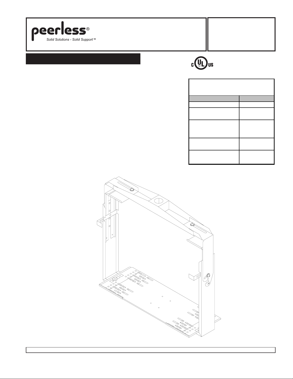
Installation and Assembly
- Jumbo 2000
®
Models: JM 2630, JM 2640,
JM 2640D, JM 2650,
JM 2650D, JM 2655,
JM 2660, JM 2665,
JM 2670, JM 2675
Please read this information first
Read entire instruction sheet before beginning assembly
and installation.
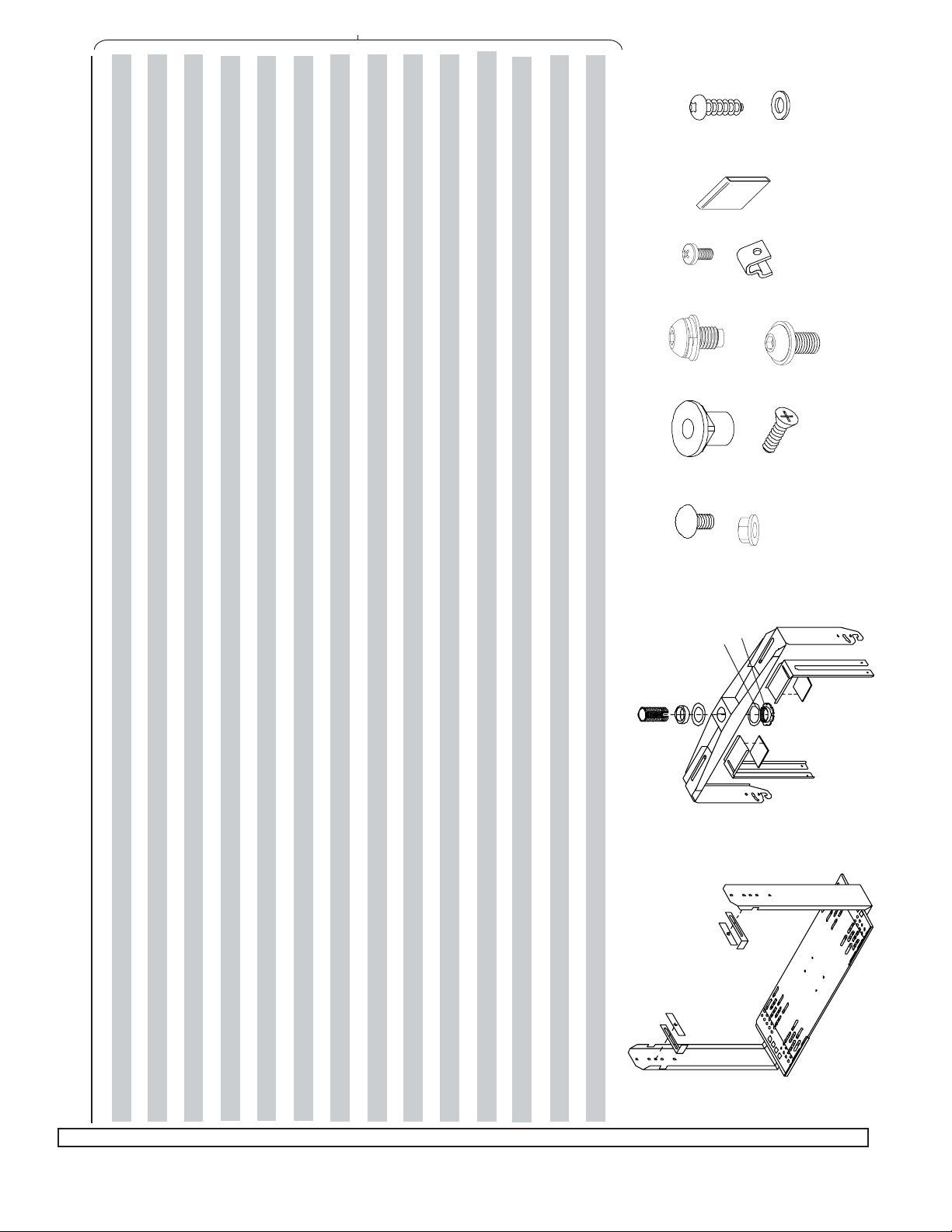
Check parts on parts listing before beginning assembly.
Many accessories are available for this product. Please
contact customer service or visit website for more
information.
This product is intended for indoor use only. Use of this
product outdoors could lead to product failure and
personal injury.
The retainer bar (D) in step 4 must be placed with extruded side towards the anti rollout hook (C).
Pay close attention to the assembly of the threaded flush
mount tube (N) in step 6. The retaining collar (K) threads
up into the horizontal support (G). The set screw (W) is
then installed from the inside of that collar into the notch
in the tube. Refer to drawings for correct placement.
The placement of set screw (W) in detail 3 of step 6 is
essential to the safety of the installation.
This product is intended for use with UL
R
Listed products and must be installed by a
qualified professional installer.
Product is UL rated up to ___ TV
si z es, per att ached chart
Model #
JM 2630
JM 2640,
JM 2640D
TV size
17"
21"
JM 2650,
JM 2650D,
27"
JM 2655
JM 2660,
JM 2665
JM 2670,
JM 2675
35"
40"
1 1
99
1 of
9
1 1
99
Visit the Peerless Web Site at www.peerlessmounts.com For customer care call 1-800-729-0307 or 708-865-8870.
ISSUED: 06-02-98 SHEET #: 128-9100-11 08-04-09
Page 2
JM 2675
128-1026
128-1027
JM 2670
128-1026
128-1027
JM 2665
128-1026
128-1027
128-1137
128-1113
128-1116
128-1137
128-1115
128-1116
128-1136
128-1111
128-1116
128-1117
128-1105
570-0024
128-1117
128-1105
570-0024
128-1117
128-1105
570-0024
128-1020
128-1335
128-1334
128-1020
128-1335
128-1334
128-1019
128-1335
128-1334
540-9432
1800-375
540-9431-1446-014
540-9432
1800-375
540-9431-1446-014
540-9432
1800-375
540-9431-1446-014
520-9207
530-1016
520-9207
530-1016
520-9207
530-1016
520-9261
520-1166
520-1041
520-9261
520-1166
520-1041
520-9261
520-1166
520-1041
520-1105
520-9250
520-1105
520-9250
520-1105
520-9250
2245-081
590-1055
500-9006
2245-081
590-1055
500-9006
2245-081
590-1055
500-9006
540-9400
540-9400
540-9400
Z
AA
Y
JM 2660
128-1026
128-1027
128-1136
128-1113
128-1116
JM 2655
128-1026
128-1027
128-1135
128-1109
128-1116
JM 2650D
128-1026
128-1027
128-1135
128-1111
128-1116
M O D E L N U M B E R
JM 2650
128-1023
128-1024
128-1130
128-1111
128-1116
JM 2640D
128-1026
128-1027
128-1134
128-1109
128-1116
JM 2640
128-1023
128-1024
128-1129
128-1109
128-1116
JM 2630
128-1023
128-1024
128-1128
128-1107
128-1116
128-1117
128-1105
570-0024
128-1117
128-1105
570-0024
128-1117
128-1105
570-0024
128-1117
128-1105
570-0024
128-1117
128-1105
570-0024
128-1117
128-1105
570-0024
128-1117
128-1105
570-0024
128-1019
128-1335
128-1334
128-1018
128-1335
128-1334
128-1018
128-1335
128-1334
128-1018
128-1335
128-1334
128-1017
128-1335
128-1334
128-1017
128-1335
128-1334
128-1016
128-1340
128-1339
540-9432
1800-375
540-9431-1446-014
540-9432
1800-375
540-9431-1446-014
540-9432
1800-375
540-9431-1446-014
540-9432
1800-375
540-9431-1446-014
540-9432
1800-375
540-9431
540-9432
1800-375
540-9431
540-9432
1800-375
540-9431
520-9207
520-9207
520-9207
520-9207
128-0067
1446-014
520-9207
128-0067
1446-014
520-9207
128-0067
1446-014
520-9207
530-1016
520-9261
530-1016
520-9261
530-1016
520-9261
530-1016
520-9261
530-1016
520-9261
530-1016
520-9261
530-1016
520-9261
520-1166
520-1041
520-1105
520-1166
520-1041
520-1105
520-1166
520-1041
520-1105
520-1166
520-1041
520-1105
520-1166
520-1041
520-1105
520-1166
520-1041
520-1105
520-1166
520-1041
520-1105
520-9250
2245-081
590-1055
520-9250
2245-081
590-1055
520-9250
2245-081
590-1055
520-9250
2245-081
590-1055
520-9250
2245-081
590-1055
520-9250
2245-081
590-1055
520-9250
2245-081
590-1055
500-9006
540-9400
500-9006
540-9400
500-9006
540-9400
500-9006
540-9400
500-9006
540-9400
500-9006
540-9400
500-9006
540-9400
W
X
U
T
R
O
P
K
J
G
L
N
S
H
E
F
M
F
11122222111111114
QTY.
4
228
2
64244
I
E
B
D
D
C
support tray left
support tray right
support tray center
vertical support arm
anti-rollout hook
retainer bar
top clamp
adhesive pad
horizontal support
tilt bracket right
tilt bracket left
fiber washer - large inside dia.
retaining collar
fiber washer - small inside dia.
spacer (only 2630-2640D models)
flush mount tube
5/16 - 18 x 1/2" carriage bolt
5/16 washer/nut combo
M10-1.5 x .7 flange nut
M6 x 18 mm flat phillips screw
M10-1.5 x 16 mm socket screw/washer combo
M10 serrated flange head screw
M5 x .8 x 10 mm screw
uni-clip
plastic cover for anti-rollout hook
#10 x 3/4 particle board screw
DESCRIPTION
A1A2A3BCDEFGHI
Visit the Peerless Web Site at www.peerlessmounts.com For customer care call 1-800-729-0307 or 708-865-8870.
JKLMNOP
RST
2 2
2 of
2 2
U
WXYZAA
99
9
99
#10 flat washer
ISSUED: 06-02-98 SHEET #: 128-9100-11 08-04-09
B
C
A3
A1
A2
Page 3
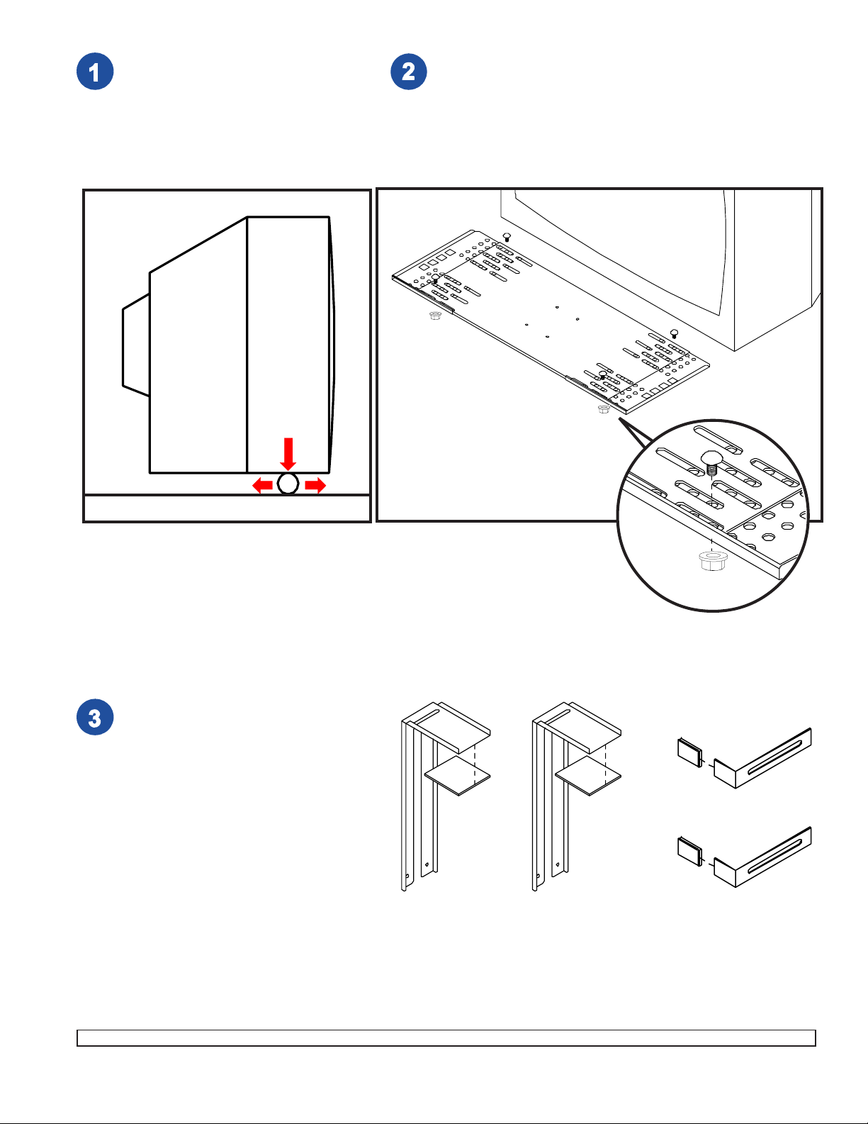
Place TV onto a piece of pipe as
shown. (Pipe should be a few inches
wider than the TV.) Roll TV back and
forth to find the balance point. This is
the center of gravity. Mark the center
of gravity on the side of the TV.
SIDE VIEW
TV
Adjust support tray (A1, A2, & A3, three pieces)
to match width of TV.
Lock support tray using four carriage bolts (O),
and washer/nut combos (P). Tighten securely.
TV
A1
A3
CENTER
OF
GRA VITY
FLOOR
Attach adhesive pads (F) to
top clamps (E).
Insert plastic covers (Y) onto
ends of anti-rollout hooks (C).
E
E
A2
O
P
Y
C
F
F
Y
C
3 3
99
3 of
9
3 3
99
Visit the Peerless Web Site at www.peerlessmounts.com For customer care call 1-800-729-0307 or 708-865-8870.
ISSUED: 06-02-98 SHEET #: 128-9100-11 08-04-09
Page 4

Attach support tray (A) to vertical support arms (B) as shown. Choose the square hole which aligns closest
with the center of gravity mark on the TV (as determined in step 1). Attach anti-rollout hooks (C) as shown
using M6 screws (S) and retainer bars (D).
Note: Extruded side of retainer bar (D) goes towards
anti-rollout hook (C). Hand tighten only.
D
C
D
C
B
R
D
C
T
A
Required for OSHPD approved installation - optional otherwise
S
B
Although top clamps (E) and anti-rollout
TV BOTTOM
A
TV (UPSIDE DOWN)
Visit the Peerless Web Site at www.peerlessmounts.com For customer care call 1-800-729-0307 or 708-865-8870.
hooks (C) [see step 5] will provide more than
adequate support for the TV, some installers
may wish to also attach the support tray to
the TV bottom.
Using uni-clips (X) and M5 screws (W) (see
instruction card in fastener pack), or #10 x
3/4" particle board screws (Z) and washers
(AA) (for attachment to mounting bosses if
present), or a combination of both, attach
support tray (A) to TV bottom. [To do this
place TV upside down on a flat stable
surface and position support tray upside
down on TV bottom.] Attach at four places
as close to the four corners of the TV bottom
as possible.
4 4
4 of
4 4
99
9
99
ISSUED: 06-02-98 SHEET #: 128-9100-11 08-04-09
W
X
Z
AA
Page 5

Safety belt, ACC 666 (Sold Sep arately), required for OSHPD approved inst allation.
Use of this belt is optional for all other installations.
belt
C
belt
B
B
C
A
belt
Optional safety belt ACC 666 (required for OSHPD approved
installation) sold separately.
Thread belt between support arms (B) and anti-rollout hooks (C),
and between support arms (B) and support tray (A).
belt
detail 1
ratchet reel
belt
Insert belt under,
behind, then through
ratchet reel.
Wrap belt around TV or monitor and mounting
surface. Insert end of belt through ratchet reel
and pull until ALL slack is out of belt.
detail 2
ratchet
handle
E
belt
belt
E
B
A
Position TV on support tray (A), thread belt through slots in top
clamps (E). Secure TV with belt as directed in detail 1, 2 & 3.
Pump ratchet handle to tighten belt. For secure
hold, ratchet reel must have at least two layers of
belt around it.
Note: Too many layers of belt around ratchet reel
will cause it to jam. To avoid this problem be sure to
remove ALL slack from belt before pumping ratchet
handle.
After belt is tight, close ratchet handle.
detail 3
release bar
To release, compress release bar and open ratchet
handle 180°.
5 5
99
5 of
9
5 5
99
Visit the Peerless Web Site at www.peerlessmounts.com For customer care call 1-800-729-0307 or 708-865-8870.
ISSUED: 06-02-98 SHEET #: 128-9100-11 08-04-09
Page 6

Note: Slots in corners of top clamps (E) and corners of vertical support arms (B) allow for the installation of
safety belt (model ACC 666, sold separately). If using this belt, install it now as shown on page five.
Position TV onto support tray (A). Position anti-rollout hooks (C) against front edge of TV.
WARNING
• Each anti-rollout hook (C) should have at least 1/4" of surface contact and fit snugly against the front edge of the
TV cabinet. If this is not the case, the support tray (A) must be adjusted smaller [see step 2], or the vertical
support arms (B) adjusted inward [see step 4].
Insert and press down on top clamps (E) with sufficient force to assure that the top clamps are fitted snugly to
the TV cabinet. Note: Top clamps (E) fit between rollout protectors (C) and vertical support arms (B) [DETAIL 1].
Press down on each top clamp (E) while securely tightening each M6 screw (S).
Press inwards on the left and right vertical support arms (B) with sufficient force to assure that the arms are fitted
snugly to the TV cabinet. By hand, thread one M10 serrated flange head screw (U) into each vertical support arm
(B) through one of three threaded holes [1, 2, or 3; DETAIL 2]. Choose the threaded holes that will allow just
enough clearance (approximately 1 1/2") between the horizontal support arm and top clamps [see step 7]. Leave
about 1/4" of exposed thread.
C
A
E
C
E
B
C
E
DET AIL 1
B
S
C
E
B
U
DET AIL 2
6 6
99
6 of
9
6 6
99
Visit the Peerless Web Site at www.peerlessmounts.com For customer care call 1-800-729-0307 or 708-865-8870.
ISSUED: 06-02-98 SHEET #: 128-9100-11 08-04-09
Page 7

Jumbo mount shown with optional ceiling plate/wall arm accessories.
FIRST: From the top fully thread flush mount tube (N) into threaded fitting in wall arm or ceiling plate. Install the
wall arm or ceiling plate according to instructions included with it.
NEXT: Attach right and left tilt brackets (H & I) to horizontal support (G) using four screw/washer combos (T).
Before tightening screws make sure tilt brackets are adjusted horizontally to align precisely with screws in the
side of vertical support arms (B). Attach horizontal support (G) to wall arm or ceiling plate using fiber washers (J
& L), spacer (M, only included with smaller models) and retaining collar (K). IMPORTANT: Retaining collar (K)
requires a safety screw (W) [refer to DETAIL 3, page 8].
FINALLY: Be sure that hooks in right and left tilt brackets (H & I) are open end forward. Hang the TV / bracket
assembly.
Insert one screw/washer combo (T) through slot in each tilt bracket (H & I). Hand tighten.
N
N
W
M
N
L
I
G
J
K
H
T
B
7 7
99
7 of
9
7 7
99
Visit the Peerless Web Site at www.peerlessmounts.com For customer care call 1-800-729-0307 or 708-865-8870.
ISSUED: 06-02-98 SHEET #: 128-9100-11 08-04-09
Page 8

When attaching the horizontal support (G) to wall arm or
ceiling plate, carefully thread retaining collar (K) onto end
of flush mount (N) tube (or extension column). Tighten at
least four complete turns ending with one of the small
threaded holes aligned with slot in the end of flush mount
tube (N) (or extension column). Insert and tighten one M5
screw (W).
WARNING
• Screw (W) is self tapping and may be hard to get
started but is essential to this installation. Failure to
install this screw can cause the mount to fall.
G
N
W
G
K
DET AIL 3
(BOTTOM VIEW)
Adjust TV to desired tilt, then TIGHTEN ALL SCREWS SECURELY. Maximum tilt is 30°. If tilt clearance is a
problem revisit step 5, DETAIL 2.
TIL T CLEARANCE
8 8
99
8 of
9
8 8
99
Visit the Peerless Web Site at www.peerlessmounts.com For customer care call 1-800-729-0307 or 708-865-8870.
ISSUED: 06-02-98 SHEET #: 128-9100-11 08-04-09
Page 9

APPLICATION: ATTACHMENT TO WOOD / CONCRETE MOUNTING SURFACE
®
SPECIFICATIONS
Product Peerless rated when attached to...
Wall Arm
WMJ 018
150 lb
(65 kg)
150 lb
(65 kg)
150 lb
(65 kg)
*
*
*
*
*
*
*
Wall Arm
WMJ 022
150 lb
(65 kg)
150 lb
(65 kg)
150 lb
(65 kg)
150 lb
(65 kg)
150 lb
(65 kg)
150 lb
(65 kg)
*
*
*
*
Double
Wall Arm
WMJ 025H
150 lb
(65 kg)
150 lb
(65 kg)
150 lb
(65 kg)
150 lb
(65 kg)
150 lb
(65 kg)
150 lb
(65 kg)
300 lb
(137 kg)
300 lb
(137 kg)
300 lb
(137 kg)
300 lb
(137 kg)
Suspended
Ceiling Plate
CMJ 450
150 lb
(65 kg)
150 lb
(65 kg)
150 lb
(65 kg)
150 lb
(65 kg)
150 lb
(65 kg)
150 lb
(65 kg)
250 lb
(113 kg)
250 lb
(113 kg)
250 lb
(113 kg)
250 lb
(113 kg)
*not compatible
Jumbo 2000 mount
Support
Model
Number
JM 2630
JM 2640
JM 2640D
JM 2650
JM 2650D
JM 2655
JM 2660
JM 2665
JM 2670
JM 2675
Tray
Depth
10"
(254 mm)
10"
(254 mm)
14"
(356 mm)
10"
(254 mm)
14"
(356 mm)
14"
(356 mm)
14"
(356 mm)
14"
(356 mm)
14"
(356 mm)
14"
(356 mm)
TV/Monitor
Screen Size
13" - 17"
(330 mm) (432 mm)
19" - 21"
(482 mm) (533 mm)
19" - 21"
(482 mm) (533 mm)
25" - 27"
(635 mm) (711 mm)
25" - 27"
(635 mm) (711 mm)
25" - 27"
(635 mm) (711 mm)
30" - 35"
(762 mm) (889 mm)
27" - 35"
(686 mm) (889 mm)
37" - 42"
(940 mm) (1067 mm)
35" - 42"
(889 mm) (1067 mm)
JUMBO 2000
Screen
Aspect
Ratio
standard
standard
standard
standard
standard
wide
standard
wide
standard
wide
Ceiling Plate
CMJ 470,
CMJ 480,
CMJ 490
150 lb
(65 kg)
150 lb
(65 kg)
150 lb
(65 kg)
150 lb
(65 kg)
150 lb
(65 kg)
150 lb
(65 kg)
300 lb
(137 kg)
300 lb
(137 kg)
300 lb
(137 kg)
300 lb
(137 kg)
WARNING
• Weight of TV or monitor not to exceed maximum load capacity (Peerless rated)!
9 9
9 of
9 9
99
9
99
ISSUED: 06-02-98 SHEET #: 128-9100-11 08-04-09
Visit the Peerless Web Site at www.peerlessmounts.com For customer care call 1-800-729-0307 or 708-865-8870.
© 2005 Peerless Industries, Inc. All rights reserved.
Peerless and Jumbo 2000 are registered trademarks of Peerless Industries, Inc.
All other brand and product names are trademarks or registered trademarks of their respective owners.
 Loading...