

Page 1
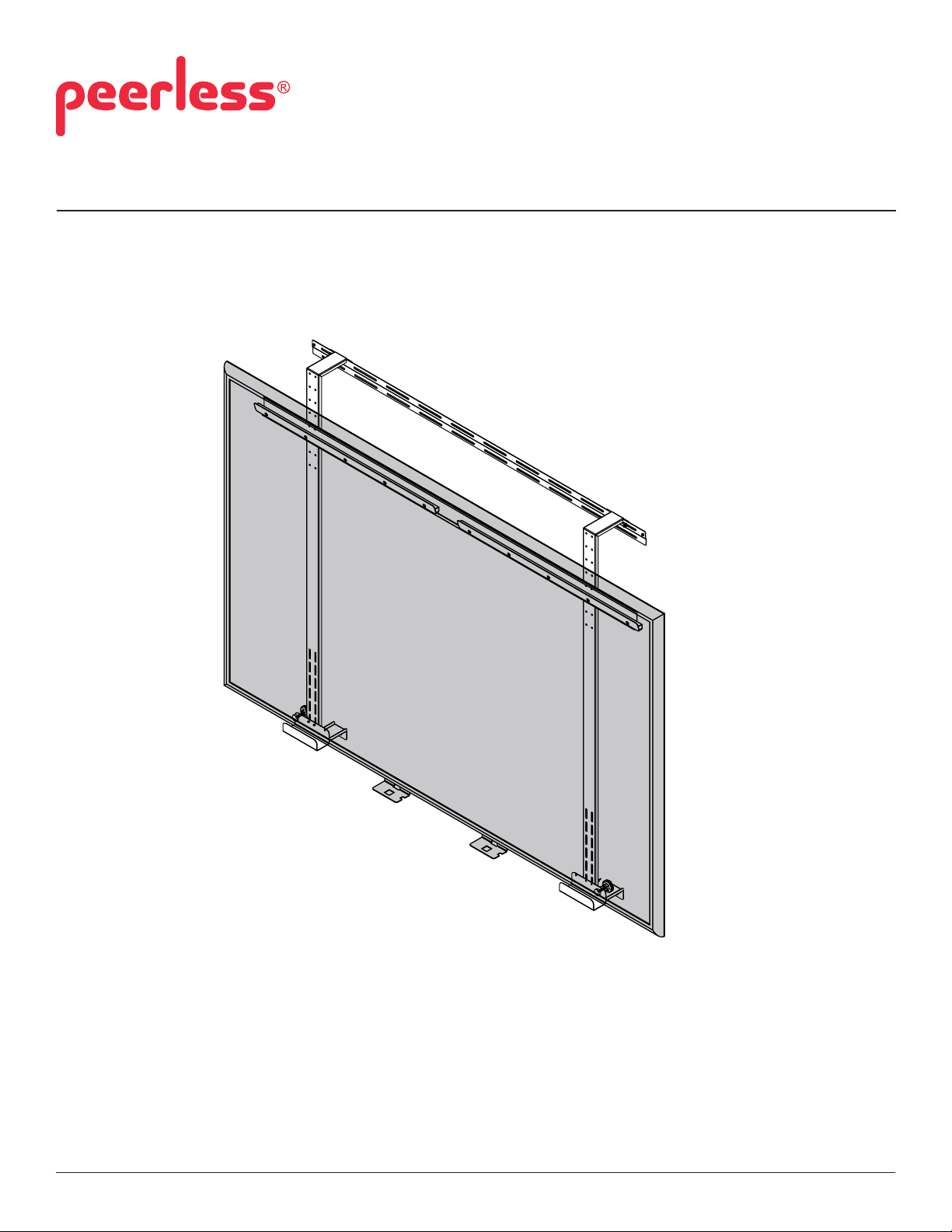
Installation and Assembly:
Wall Mount for SMARTboard SB685/SB690
Model: IWB600-WB
1 of 7
Max Load Capacity: 50 lb (22.6 kg)
ISSUED: 02-03-10 SHEET #: 125-9095-5 06-02-10
Page 2

PARTS LIST
A
Description Qty. Part #
wall plate 1 095-4652
B upper cross support 1 095-4962
C support bracket 2 095-4667
D vertical support 2 095-4666
E rubber bumper 2 590-1159
F #10 washer 2 540-9442
G M4 x 6 mm phillips screw 2 520-2032
H #10-32 x 3/8 thumb screw 6 560-2107
I knob 2 560-0223
J 1/4 washer 6 540-9444
K M4 nylock nut 4 530-1055
L M5 nylock nut 8 530-1019
M M4 x 8 mm phillips screw 4 520-2237
N M5 x 20 mm phillips screw 8 510-1208
A
B
C
D E
J
K
F
G I
H
L M N
2 of 7
ISSUED: 02-03-10 SHEET #: 125-9095-5 06-02-10
Page 3

WARNING
• Installer must verify that the supporting surface will safely support the combined load of the equipment and all
attached hardware and components.
NOTE: Make sure ange of wall bracket is located on top as shown in detail 1
1
Be sure wall bracket (A) is level and in desired position. Then use wall bracket (A) as a template to mark center
of four mounting holes. Drill four mounting holes. Attach wall bracket (A) to mounting surface using four screws
provided by installer and four 1/4 washers (J) if required. Once secure, wall bracket (A) will be ush with the top of
the vertical bracket (D).
Fasten two M4 x 6 mm phillips screws (G) into ends of wall bracket (A) as shown in Detail 1.
NOTE: Vertical brackets (D) may be used to determine location of wall bracket (A).
A
TOP
A
Screws provided by installer
Flange
G
Detail 1
J
3 of 7
ISSUED: 02-03-10 SHEET #: 125-9095-5 06-02-10
Page 4

Secure Vertical brackets (D) to wall bracket (A) using two #10-32 x 3/8 thumb screws (H) and #10 at washers
2
(F).
F
H
Detail 2
D
Secure SMARTboard channel to upper cross support (B) using eight M5 x 20 mm phillips screws (N) and eight
3
M5 nylock nuts (L).
NOTE: Make sure to skip attachment point as shown below.
Skip attachment point
B
L
SMARTboard
channel
Skip attachment point
4 of 7
N
ISSUED: 02-03-10 SHEET #: 125-9095-5 06-02-10
Page 5

Secure upper cross support (B) to vertical supports (D) using four M4 x 8 mm phillips screws (M), and
4
M4 nylock nuts (K).
D
K
B
M
B
M
Hook SMARTboard into SMARTboard channel on upper cross support (B).
5
SMARTboard
channel
SMARTboard
Detail 3
B
5 of 7
Detail 4
ISSUED: 02-03-10 SHEET #: 125-9095-5 06-02-10
SMARTboard
channel
Page 6

Fasten two support brackets (C) to vertical supports (D) using four #10-32 x 3/8 thumb screws (H).
6
Slide support brackets (C) up until bottom of SMARTboard rests on support as shown in detail 5.
Tighten four #10-32 x 3/8 thumb screws (H).
H
H
C
Fasten knob (I) through outside hole in support bracket (C) to determine rubber bumper (E) placement.
7
Secure rubber bumper (E) to board.
Repeat on opposite side of board.
C D
Detail 5
E
C
6 of 7
I
ISSUED: 02-03-10 SHEET #: 125-9095-5 06-02-10
Page 7

Secure bottom of vertical supports (D) to mounting surface using two screws provided by installer,
8
and 1/4 washers (J) if required.
NOTE: Make sure mounting surface is suitable to hold the weight of the mount and smart board.
Screws provided by
installer
J
D
7 of 7
All other brand and product names are trademarks or registered trademarks of their respective owners.
ISSUED: 02-03-10 SHEET #: 125-9095-5 06-02-10
© 2010, Peerless Industries, Inc. All rights reserved.
 Loading...