

Page 1
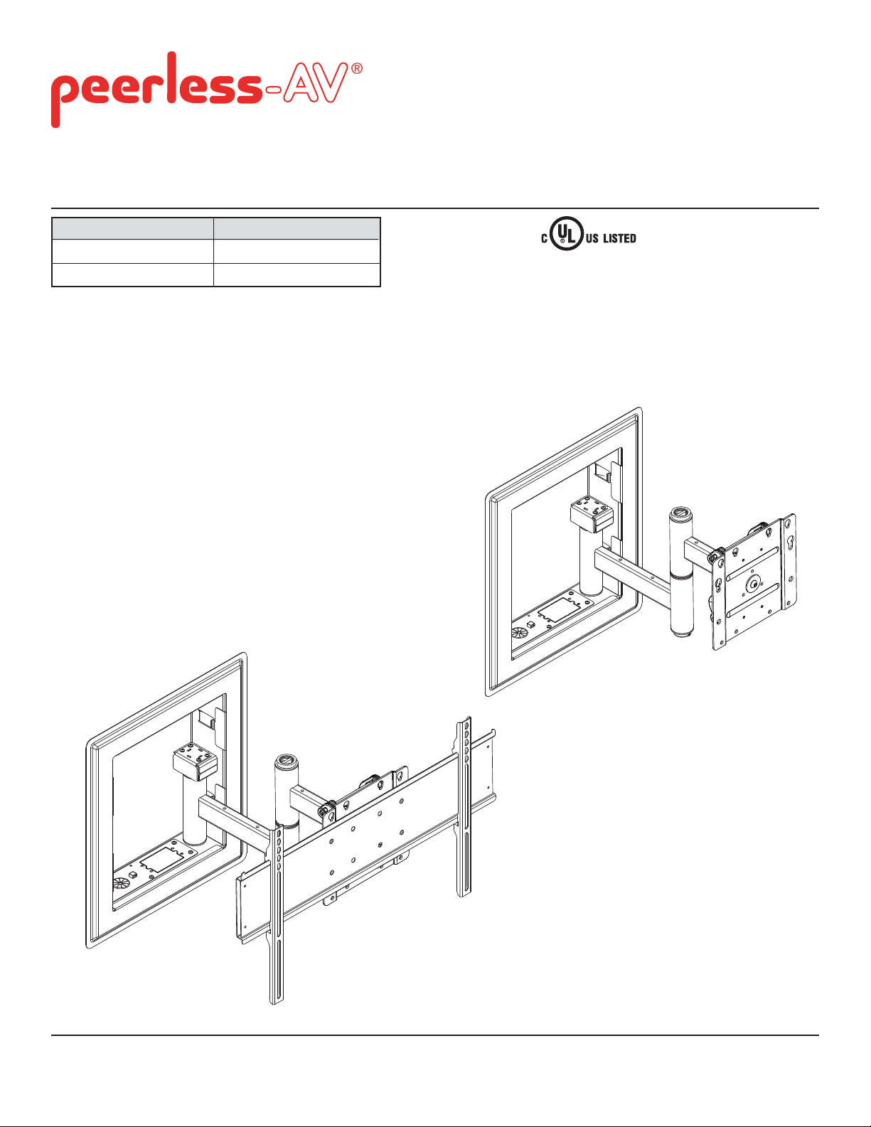
Installation and Assembly:
In-wall Mount for 32" to 71" Flat Panel Displays
Model# Display size range
IM760P, IM760P-S 32" to 71" (81 to 180 cm)
IM760PU, IM760PU-S 32" to 65" (81 to 165 cm)
This product is intended for use with UL
Listed products and must be installed by a
qualifi ed professional installer.
Maximum UL Load Capacity: 200 lb (91 kg)
IM760P
IM760P-S
IM760PU
IM760PU-S
2300 White Oak Circle • Aurora, Il 60502 • (800) 865-2112 • Fax: (800) 359-6500 • www.peerless-av.com
ISSUED: 12-04-07 SHEET #: 095-9279-8 (2013-10-01)
Page 2
NOTE: Read entire instruction sheet before you start installation and assembly.
WARNING
• Do not begin to install your Peerless product until you have read and understood the instructions and warnings
contained in this Installation Sheet. If you have any questions regarding any of the instructions or warnings, please
call Peerless customer care at 1-800-865-2112.
• This product should only be installed by someone of good mechanical aptitude, has experience with basic building
construction, and fully understands these instructions.
• Make sure that the supporting surface will safely support the combined load of the equipment and all attached hardware and components.
• Never exceed the Maximum UL Load Capacity.
• If mounting to wood wall studs, make sure that mounting screws are anchored into the center of the studs. Use of
an "edge to edge" stud fi nder is highly recommended.
• Always use an assistant or mechanical lifting equipment to safely lift and position equipment.
• Tighten screws fi rmly, but do not overtighten. Overtightening can damage the items, greatly reducing their holding
power.
• This product was designed and intended to be mounted to the following supporting surfaces checked below with
the hardware included in this product as specifi ed in the installation sheet.
• This product is intended for indoor use only. Use of this product outdoors could lead to product failure and personal
injury.
• This product was designed to be installed on the following wall construction only;
WALL CONSTRUCTION ADDITIONAL HARDWARE REQUIRED
x Wood Stud None
Tools Needed for Assembly
• stud fi nder ("edge to edge" stud fi nder is recommended)
• phillips screwdriver
• drill
• 5/32" bit for wood stud wall
• level
Table of Contents
Parts List............................................................................................................................................................................ 3, 4
Installation to Wood Stud Wall ........................................................................................................................................... 5, 6
Installing Arm to In-wall Box ...................................................................................................................................................7
Disassemble Mounting Plate ..................................................................................................................................................8
Attaching Mounting Plate to Display with VESA Mounting Pattern ........................................................................................8
Attaching Adapter Plate to Display .................................................................................................................................. 9, 10
Installing and Removing Flat Panel Display .........................................................................................................................11
Adjusting Flat Panel Display .................................................................................................................................................11
Cable Management ............................................................................................................................................................. 12
2 of 12
ISSUED: 12-04-07 SHEET #: 095-9279-8 (2013-10-01)
Page 3
Before you begin, make sure all parts shown are included with your product.
Parts List
IM760P IM760P-S IM760PU IM760PU-S
Description Qty. Part # Part # Part # Part #
arm assembly 1 095-P1145 095-C4145 095-P1145 095-C4145
A
in-wall box 1 095-P1989 095-C4989 095-P1989 095-C4989
B
arm axle 1 095-P1519 095-C4519 095-P1519 095-C4519
C
outer trim 1 095-P1517 095-C4517 095-P1517 095-C4517
D
#14 x 2.5" wood screw 6 5S1-015-C03 5S1-015-C03 5S1-015-C03 5S1-015-C03
E
cable bushing 2 590-1295 590-1295 590-1295 590-1295
F
cable tie 8 590-1168 590-1168 590-1168 590-1168
G
plastic finishing cap 2 590-1123 590-1123 590-1123 590-1123
H
cable management clips 8 590-1166 590-1166 590-1166 590-1166
J
4 mm allen wrench 1 560-0072 560-0072 560-0072 560-0072
K
M5 x 12 mm phillips screw 4 520-1027 520-2008 520-1027 520-2008
L
M4 x 20 mm phillips screw 4 504-9020 504-2014 N/A N/A
M
M4 x 30 mm phillips screw 4 520-1133 520-1133 N/A N/A
N
M6 x 20 mm phillips screw 4 520-9402 520-9402 N/A N/A
O
M6 x 30 mm phillips screw 4 510-9109 510-9109 N/A N/A
P
M6 x 40 mm phillips screw 4 520-1584 520-1207 N/A N/A
Q
retaining spacer 4 590-5005 590-5005 N/A N/A
R
universal adapter plate 1 N/A N/A 201-P1110 201-C4110
T
shallow adapter bracket 2 N/A N/A 201-P1514 201-C4514
V
M5 x 10 mm phillips screw 4 N/A N/A 520-9250 520-9250
W
X M10 x 17 mm serrated washer head 4 N/A N/A 520-1105 520-7105
6 mm allen wrench 1 N/A N/A 560-9716 560-9716
Y
adapter bracket fastener pack 1 N/A N/A 200-8651-1 200-8651-1
Z
Parts may appear slightly different than illustrated.
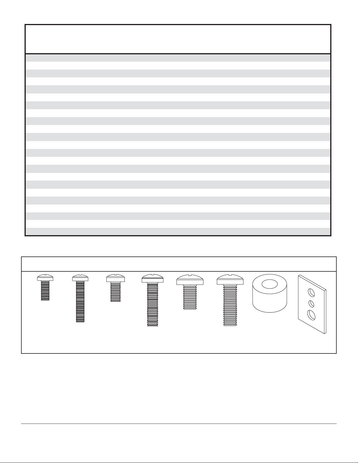
Adapter Bracket Fastener Pack (Z)
M5 x 12 mm (4)
(520-1027)
M5 x 25 mm (4)
(520-9543)
M6 x 12 mm (4)
(520-1128)
M6 x 25 mm (4)
(520-1208)
M8 x 12 mm (4)
(520-9571)
M8 x 25 mm (4)
(520-1031)
.75" spacer (4)
(540-1059)
Multi-washer (4)
(580-1398)
3 of 12
ISSUED: 12-04-07 SHEET #: 095-9279-8 (2013-10-01)
Page 4
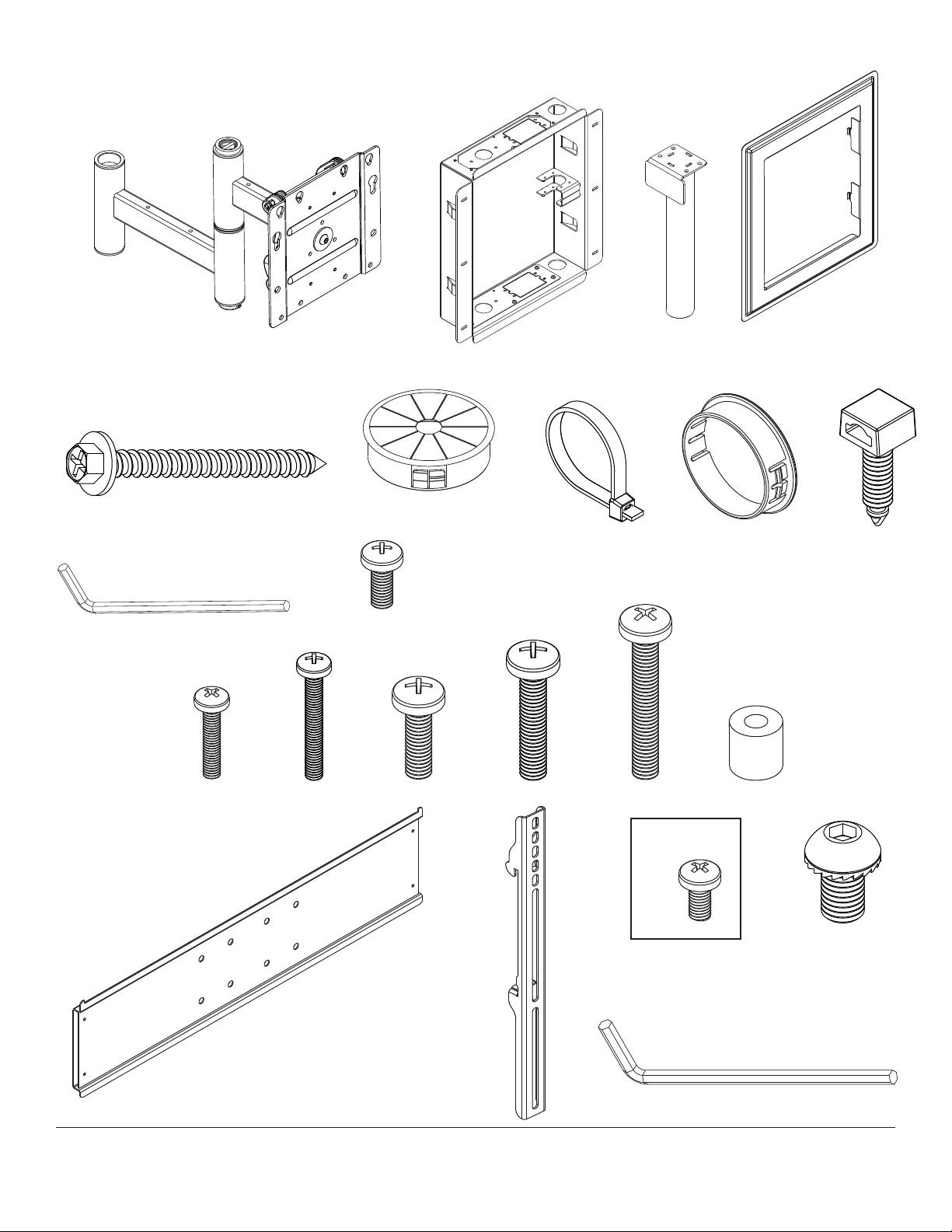
Part List Continued
Parts may appear slightly different than illustrated.
A
ARM
ASSEMBLY
ADAPTER
PLATE
K
E
MN
BC
F
G
H
L
OPQR
D
J
T
V
4 of 12
Used with specifi c
mounts only
W
X
Y
ISSUED: 12-04-07 SHEET #: 095-9279-8 (2013-10-01)
Page 5

Installation to Wood Stud Wall
In-wall box (B) can be installed between two 2" x 4"studs 16" off center. Use a stud fi nder to locate the edges of the
1
stud. Use of an edge-to-edge stud fi nder is highly recommended. Based on its edges, draw vertical lines down the
inside edges of stud’s. Mark desired center of display between studs. Draw a horizontal line above desired center
of display as indicated in fi gure 1.1 or 1.2. Draw a second horizontal line 16-5/8" (422mm) below this line to outline
wall opening between inside edges of studs. Remove drywall inside cut outline.
Display center with models
IM760P and IM760P-S:
Center of adapter plate will be located 6"
(152mm) below the top cut line.
NOTE: Center of adapter plate may not
represent display center.
Placement of in-wall box will depend on
the display center and location of display
mounting holes in relation to adapter
plate.
NOTE: Depending on right or left side
mount orientation shown in fi gure 1.3
in step 1-1, display center will be 6.39"
(162mm) from the inside edge of stud.
6"
(152mm)
CENTER OF
ADAPTER PLATE
8.11"
(206mm)
fi g. 1.1
14.5"
(368mm)
(162mm)
TOP CUT LINE
16-5/8"
(422mm)
6.39"
Display center with models
IM760PU and IM760PU-S:
Center of display will be located
7-7/8" (200mm) below the top
cut line.
NOTE: Depending on mount
orientation shown in fi gure 1.3
in step 1-1, display center will
be 6.39" (162mm) from the
inside edge of stud.
NOTE: Depending on right
or left side mount orientation
shown in fi gure 1.3 in step 1-1,
display center will be 6.39"
(162mm) from the inside edge
of stud.
7-7/8"
(200mm)
fi g. 1.2
14.5"
(368mm)
CENTER OF DISPLAY
8.11"
(206mm)
6.39"
(162mm)
TOP CUT LINE
16-5/8"
(422mm)
5 of 12
ISSUED: 12-04-07 SHEET #: 095-9279-8 (2013-10-01)
Page 6

Installation to Wood Stud Wall (continued)
WARNING
• Installer must verify that the supporting surface will safely support the combined load of the equipment and all
attached hardware and components.
• Tighten wood screws so that wall plate is fi rmly attached, but do not overtighten. Overtightening can damage the
screws, greatly reducing their holding power.
• Never tighten in excess of 80 in. • lb (9 N.M.).
• Make sure that mounting screws are anchored into the center of the stud. The use of an "edge to edge" stud fi nder
is highly recommended.
• Hardware provided is for attachment of mount through max 5/8" thick drywall or plaster into 2" x 4" wood studs.
Installers are responsible to provide hardware for other types of mounting situations.
• Do not install this unit in a fi re rated wall. If you are unsure, contact your building architect or local building
department.
In-wall box can be fl ipped for left of right side mount orientation as shown in fi gure 1.3. Insert in-wall box (B) into
1-1
cut-out. Level in-wall box, and mark the center of the six mounting holes. Drill six 5/32" (4mm) dia. holes 2-1/2"
(64mm) deep. Make sure in-wall box is level, secure it using six #14 x 2-1/2" wood screws (E) as shown in fi gure
1.4.
fi g. 1.3
RIGHT
ORIENTATION
8.11"
(206mm)
6.39"
(162mm)
LEFT
ORIENTATION
fi g. 1.4
B
E
6.39"
(162mm)
8.11"
(206mm)
6 of 12
ISSUED: 12-04-07 SHEET #: 095-9279-8 (2013-10-01)
Page 7

Installing Arm to In-wall Box
Insert arm axle (C) through arm assembly (A) as shown
2
in fi gure 2.1.
Position arm axle (C) and arm assembly (A) into axle
support bracket of in-wall box (B) then seat arm axle
through bottom hole of in-wall box as shown in fi gure 2.2.
Secure arm axle to in-wall box using four M5 x 12mm
phillips screws (L) as shown in fi gure 2.3.
C
B
AXLE
SUPPORT
BRACKET
C
A
fi g. 2.1
L
C
fi g. 2.2
Installing Outer Trim
Insert tabs of outer trim (D) into notches of
3
in-wall box (B) as shown in fi gure 3.1.
A
fi g. 2.3
B
NOTCHES
TABS
D
fi g. 3.1
7 of 12
ISSUED: 12-04-07 SHEET #: 095-9279-8 (2013-10-01)
Page 8

Attaching Adapter Plate to Display with
VESA® Mounting Pattern
NOTE: For installing display using universal adapter plate, skip to step 5.
4
Identify VESA mounting pattern on back of your display and choose hole pattern on adapter plate and required
fasteners as shown in fi gure 4.2.
Secure adapter plate to back of display as shown in fi gure 4.1 using fasteners indicated in fi gure 4.2.
NOTE: If hole pattern is in a pocket and requires M4 screws, attach adapter plate to back of display using four
M4 x 30mm screws (N) and four retaining spacers (R) as indicated in fi gure 4.1.
NOTE: Spacers may not be used, depending upon the type of display.
Skip to step 7
fi g.4.1
WARNING
• If screws don't get three complete turns in the
display inserts or if screws bottom out and adapter
plate is still not tightly secured, damage may occur
to display or product may fail.
• Do not tighten screws with excessive force.
Overtightening can cause damage to mount.
• Do not lift more weight than you can handle. Use additional man power or mechanical lifting equipment
to safely handle placement of the display.
Mounting Patterns
®
VESA
100 x 200
ADAPTER
PLATE
VESA
DISPLAY
NOTE: For displays with a hole
pattern in a pocket,
spacers go between
adapter plate and display
when using M4 x 30mm
screws.
®
200 x 200
M4 x 20mm screws (M) or
M4 x 30mm screws (N) with spacer (R)
8 of 12
M6 x 20mm (O), M6 x 30mm (P)
or M6 x 40mm screws (Q)
fi g. 4.2
ISSUED: 12-04-07 SHEET #: 095-9279-8 (2013-10-01)
Page 9

Installing Universal Adapter Plate to Display
Using the hole pattern shown in detail 1, attach the adapter plate to universal adapter
5
plate (T) with four M10 x 17mm screws (X) as shown. Tighten screws using 6mm allen wrench (Y).
T
LARGE
HOLES
HOLE PATTERN
FOR USE WITH
UNIVERSAL
ADAPTER
X
ADAPTER PLATE
DETAIL 1
WARNING
• Tighten screws so display brackets are fi rmly attached to display. Do not tighten with excessive force.
Overtightening can cause stress damage to screws, greatly reducing their holding power and possibly causing
screw heads to become detached. Tighten to 40 in. • lb (4.5 N.M.) maximum torque.
• If screws don't get three complete turns in the display inserts or if screws bottom out and bracket is still not tightly
secured, damage may occur to display or product may fail.
PLATE
To prevent scratching the display, set a cloth on a fl at, level surface that will support the weight of the display.
6-1
Place display face side down. If display has knobs on the back, remove them to allow the adapter brackets to be
attached. Place adapter brackets (V) on back of display, align to holes, and center on back of display as shown in
fi gure 6.1. Attach the adapter brackets to the back of the display using the appropriate combination of screws,
multi-washers, and spacers as shown in fi gure 6.2 or fi gure 6.3.
NOTE: Top and bottom holes must always be used.
Verify that all holes are properly aligned, and then tighten screws using a phillips screwdriver.
X
MULTI-WASHER
MEDIUM HOLE FOR M5 SCREWS
SMALL HOLE FOR M4 SCREWS
LARGE HOLE FOR M6 SCREWS
fi g 6.1
CENTER BRACKETS
VERTICALLY ON BACK OF
DISPLAY
V
Note: "X" dimensions should be equal.
X
Notes:
• The number of fasteners used will vary,
depending upon the type of display.
• Multi-washers and spacers may not be
used, depending upon the type of display.
• Use the corresponding hole in the multiwasher that matches your screw size.
NOTE: For fl at back displays proceed to step 6-2. For bump-out or recessed back display skip to step 6-3
9 of 12
ISSUED: 12-04-07 SHEET #: 095-9279-8 (2013-10-01)
Page 10

For Flat Back Display
Begin with the shortest length screw, hand thread through multi-washer and adapter bracket into display as
6-2
shown below. Screw must make at least three full turns into the mounting hole and fi t snug into place. Do not
over tighten. If screw cannot make three full turns into the display, select a longer length screw from the baffl ed
fastener pack. Repeat for remaining mounting holes, level brackets and tighten screws.
NOTE: Spacers may not be used, depending upon the type of display.
If you have any questions, please call Peerless customer care at 1-800-865-2112.
fi g. 6.2
DISPLAY
MULTI-WASHER
SCREW
ADAPTER BRACKET
(V)
For Bump-out or Recessed Back Display
Begin with longer length screw, hand thread through multi-washer, adapter bracket and spacer in that order into
6-3
display as shown below. Screw must make at least three full turns into the mounting hole and fi t snug into place.
Do not over tighten. If screw cannot make three full turns into the display, select a longer length screw from the
baffl ed fastener pack. Repeat for remaining mounting holes, level brackets and tighten screws.
DISPLAY
SPACER
If you have any questions, please call Peerless customer care at 1-800-865-2112.
fi g. 6.2
MULTI-WASHER
SCREW
ADAPTER BRACKET
(V)
10 of 12
ISSUED: 12-04-07 SHEET #: 095-9279-8 (2013-10-01)
Page 11

Adjustment of Flat Panel Display
TIL T Adjustment: Adjust tension knob on side of
7
mount to desired tension to enable tilt adjustment
and balance your display size and weight as
shown in fi gure 7.1. Push or pull from top or
bottom of display to adjust tilt as shown. The tilt
can be adjusted to a maximum of 10° forward or 5°
backward. Retighten tension knob.
ROLL Adjustment: Loosen M5 x 25mm screws
using 4mm allen wrench (K). Rotate display either
5° clockwise or counter-clockwise, level display
then tighten M5 x 25mm screws using 4mm allen
wrench (K) as shown in fi gure 7.2.
FOR VERTICAL HEIGHT ADJUSTMENT: Tighten
or loosen two M8 x 40mm screws an equal
number of turns to achieve ± 1" of vertical height
adjustment as shown in detail 1.
CAUTION
• Do not tighten screws with excessive force.
• Be careful not to pinch fi ngers when opening and
closing mount from the wall.
Adjustment of Flat Panel Display
FOR PORTRAIT OR LANDSCAPE Display
8
ORIENTATION: Remove two M5 x 12mm screws,
one M5 x 6mm screw and rotation block from top of
tilt head as shown in top view and rear view. Gently
grasp sides of display and rotate display into portrait
or landscape position as shown and reinstall rotation
block with two M5 x 12mm screws and one M5 x
6mm screw. NOTE: M5 x 6mm screw required in
landscape orientation only.
WARNING
• M10 x 15mm screws (E) must be securly tightened
before changing orientation of wall arm assembly
(A). Failure to lock adapter bracket can cause
display to come off of mount.
Fig. 7.1
TENSION
KNOB
Fig. 7.2
M5 X 10MM
M8 X 40MM
ROTATION BLOCK
M5 X 12MM SCREWS
TOP VIEW
M5 X 6MM
SCREWS
M5 X 6MM SCREWS
M5 X 12MM
SCREWS
11 of 12
ROTATION BLOCK
REAR VIEW
ISSUED: 12-04-07 SHEET #: 095-9279-8 (2013-10-01)
Page 12

Cable Management
For optional installation of UL listed single receptacle electrical box, access plates located on the bottom or top of
9
in-wall box can be temporarily removed to install electrical box as shown in fi gure 9.1.
ACCESS
PLATE
9-1
fi g. 9.1
Insert up to eight cable management clips (J) into the desired positions in the arm assembly and in-wall box as
shown in fi gure 9.2 for routing cables.
Insert cable bushing (F) into top or bottom hole of in-wall box for routing cables through in-wall box. Plastic
fi nishing caps (H) can be used in holes where cables are not being routed.
NOTE: Make sure cables have enough slack to allow full movement of the arm.
Use cable ties (G) to secure cables to cable management clips as shown in fi gure 9.3.
DISPLAY NOT SHOWN FOR CLARITY
J
CABLES
J
G
J
F or H
Patented. Utilty Patent No. 8,348,212; 8,517,322; 8,028,964; 1110143B; ZL2007100841191.
fi g. 9.2
DISPLAY NOT SHOWN FOR CLARITY
12 of 12
All other brand and product names are trademarks or registered trademarks of their respective owners.
fi g. 9.3
ISSUED: 12-04-07 SHEET #: 095-9279-8 (2013-10-01)
© 2013, Peerless Industries, Inc. All rights reserved.
 Loading...