

Page 1
owner’s manual
X-VCA mixing consoles
(PRELIMINARY COPY)
Page 2
X-VCA owner’s manual
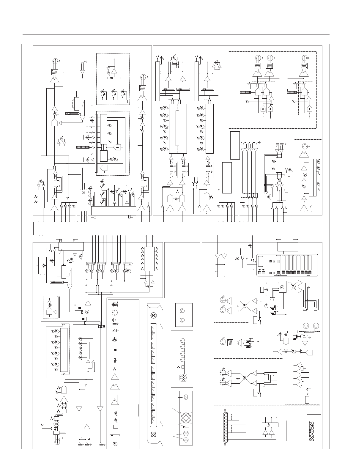
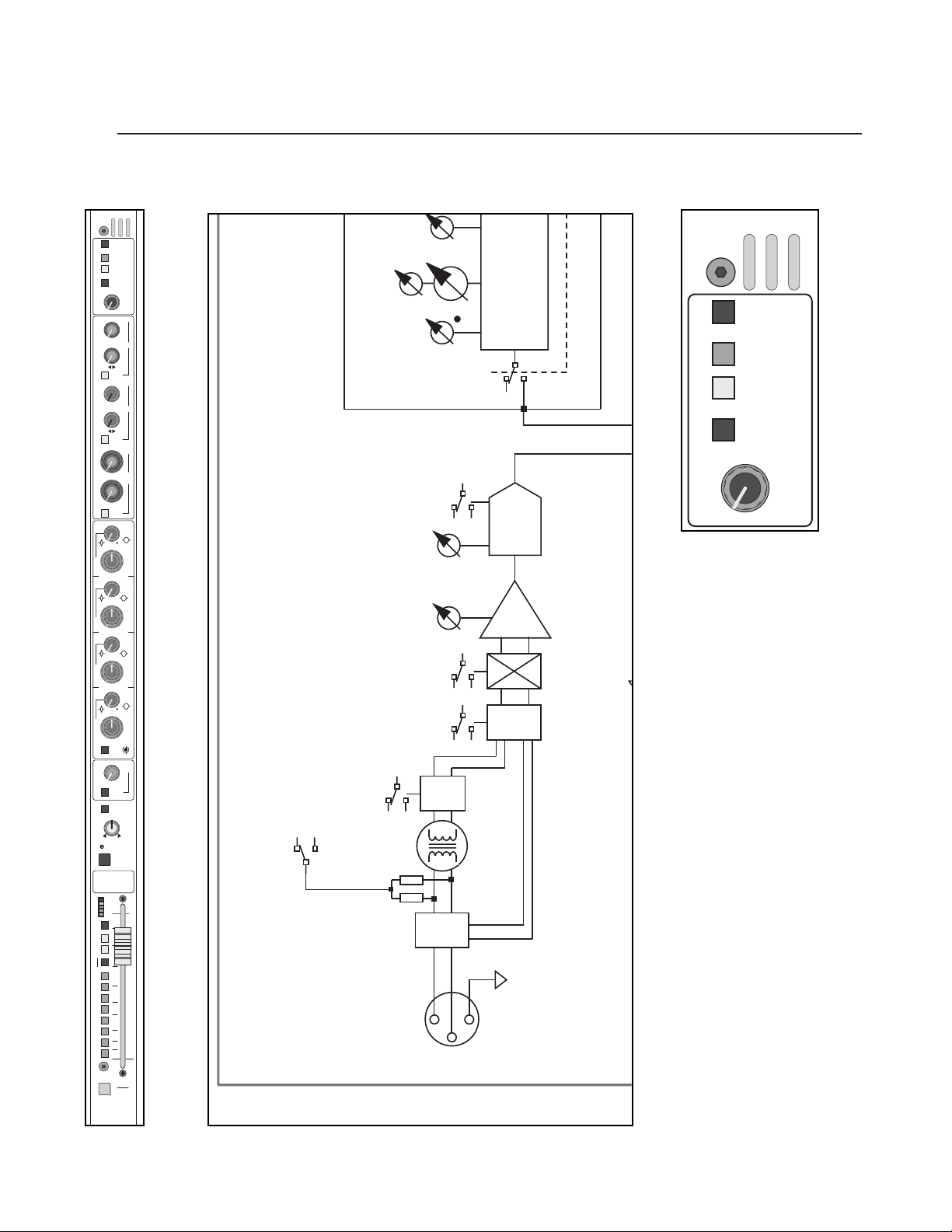
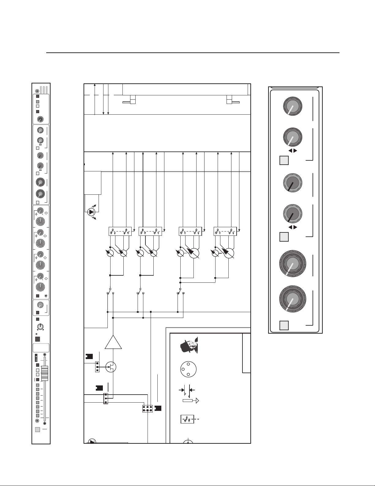
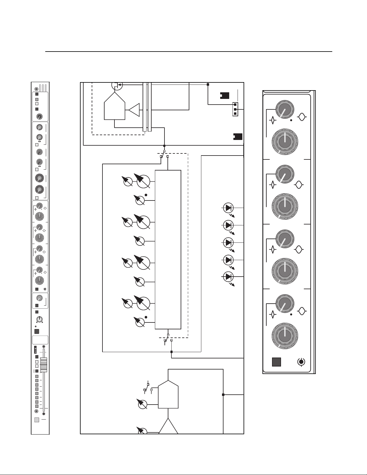
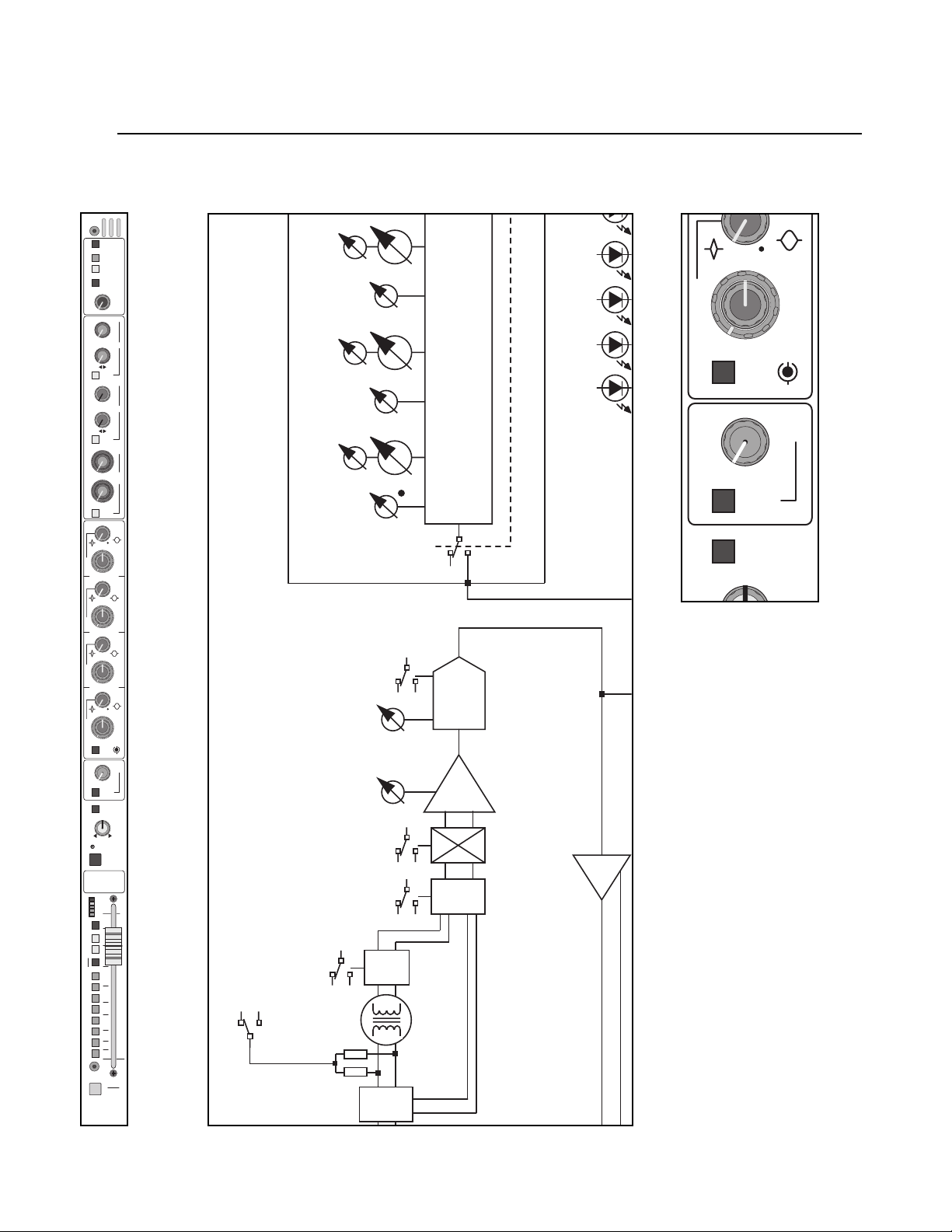
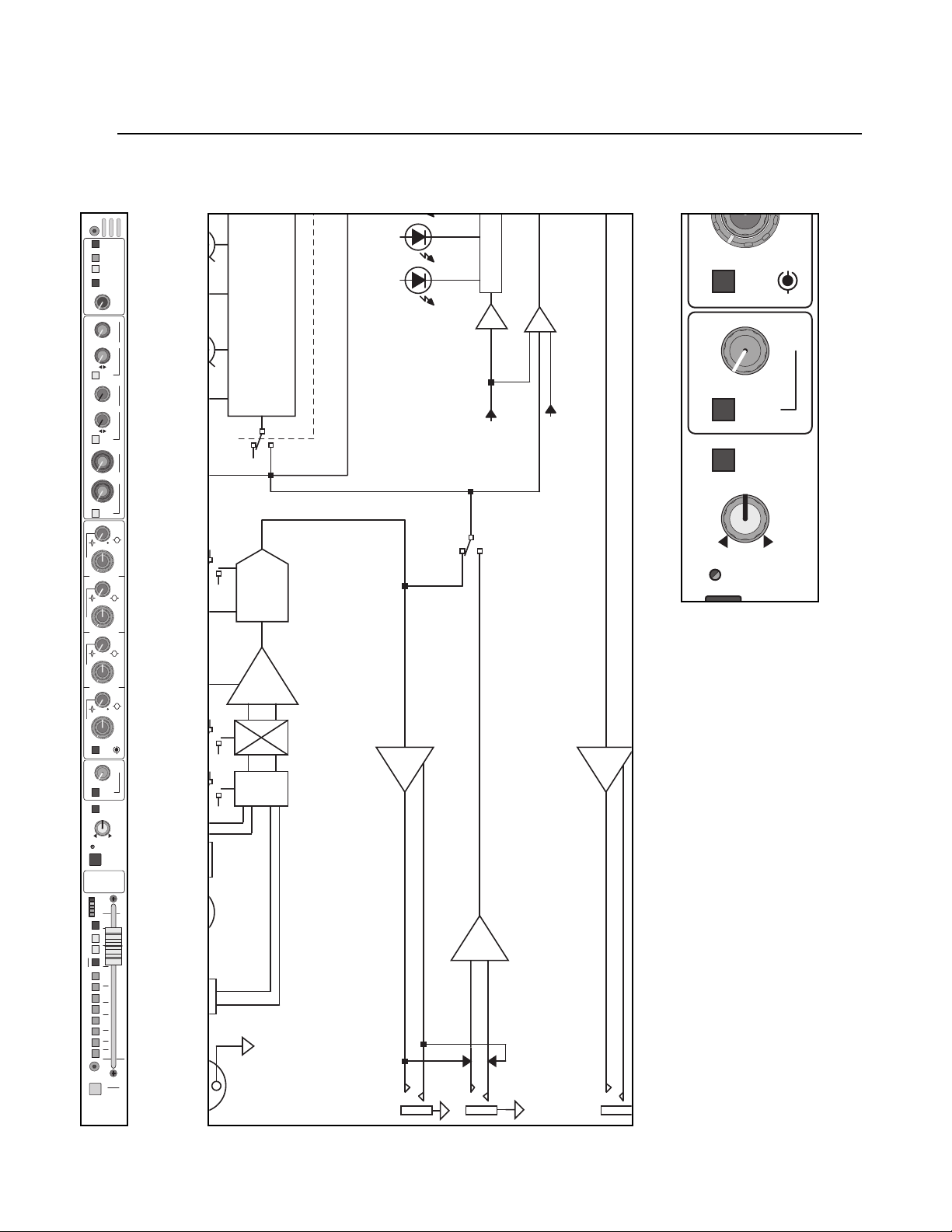
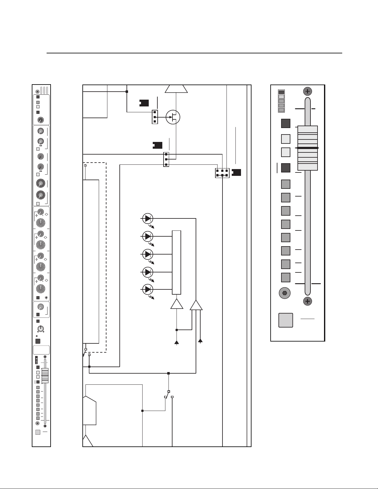
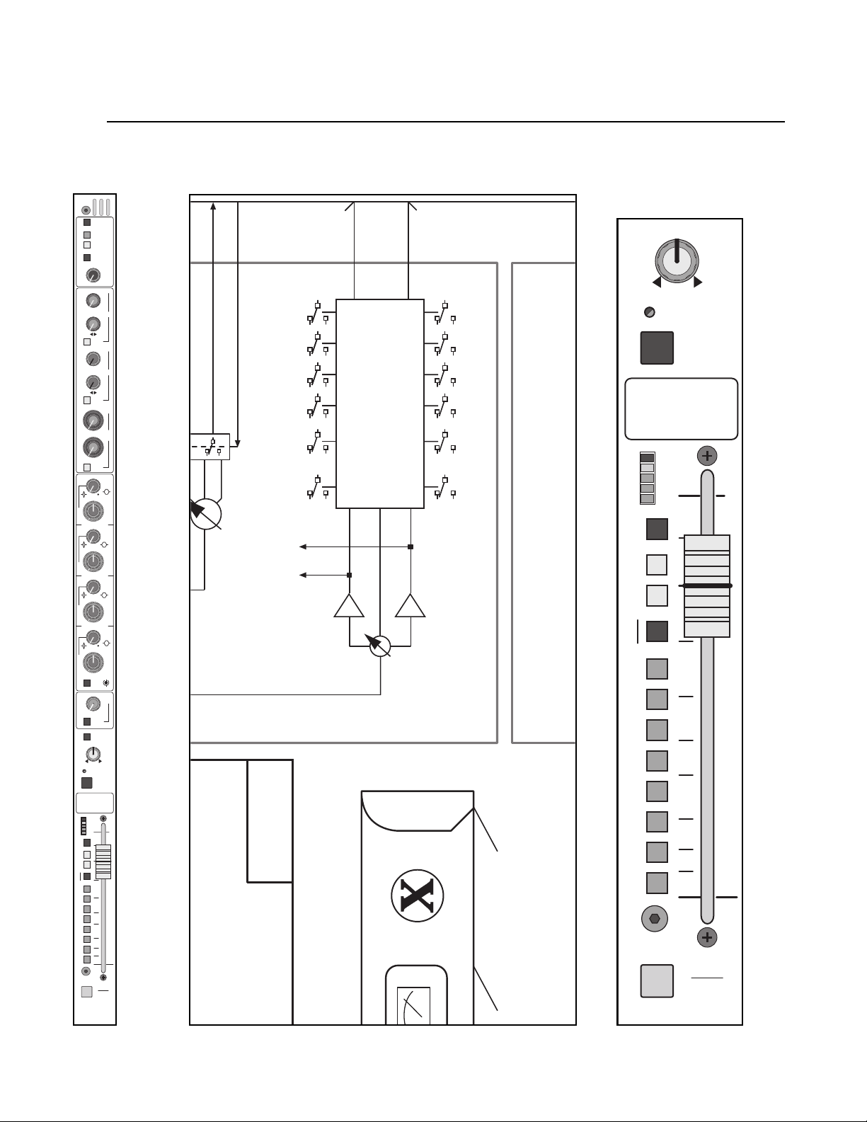
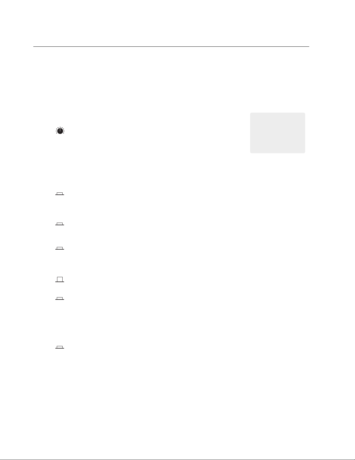
X-VCA block diagram
2
4
4
1
3
5
6
7
(1 OF 8 SHOWN)
X-VCA GROUP OUTPUT
PAN
GROUP
L-R
GROUP
SWITCHES
BUS ASSIGN
MONO
GRP
BAL OUT
OPTION
XFORMER
ON
INSERT
GROUP
GROUP INSERT
MIX AMP
POST
GROUP
GROUP PRE
SEND RTN
MIX
GRP
+10
VCA
GC
∑
GRP
PK
MATRIX
M1M2M3
MUTE
SENDS
GROUP
METER SEND
VCA MASTER
SIG
GROUP PRE
POST
GROUP
BUSES 1-8
GROUP
GROUP
FADER
POST
GROUP
ATTENUATION
M4
MICRO
CONTROL
LATCHES
VCA ASSIGN
12357
METER
TO EXT MTX
BUS IN
AFL MODE
TO GROUP
CV
ON
AUTO
COMP
ON
THRESH
9
121518
ON
THRESH
AUX POST
AUX PRE
& SWITCHING
SOLO CONTROL
SOLO LEFT
MIX BUS
ODD/EVEN PAIRS
TO ADJACENT CHANNEL
LINK
VOX PERC
SOFT
KNEE
21
ON
GATE
SOLO RIGHT
VCA MASTERS
MUTE
STEREO PAIR
AUX ODD/EVEN
AUX
SOLO
SOLO
GROUP
ASSIGN
TO
INPUT
L / R
SOLO
PK
SIG
TO RIBBON
CV
UNITY
(1 OF 8 SHOWN)
EDIT
ASSIGN
THRESH
-45 +15
RATIO
1:1 20:1
COMPRESSOR CONTROL
GAIN
0 DB +20
RATIO
1:5 1:1
-60 -20
THRESH
CONTROL
EXPANDER
PFL
VCA
SLAVE
LATCHES
VCA ASSIGN
MUTE
TO GROUP FADER
GROUP
FACE
CARD
MICRO
INTER-
GROUP
MICRO
CARDS
VCA
SOLO
TIMING CONTROL
RMS
DETECTOR
SAFE
PREVIEW
FROM
FADER
MASTER
PART OF GROUP MICRO INTERFACE CARD
GROUP DYNAMICS SUB-CARD
AUX
1 OF 4
CIRCUITS
CARD
MICRO
MASTER
AUX
BAL OUT
OPTION
XFORMER
AUX POST
TO SOLO
SWITCHING
+10
AUX
MUTE
AUX
LEVEL
TO SOLO
AUX PRE
SWITCHING
AUX
INSERT RTN
AUX
INSERT
MUTE
SEND RTN
GC
SAFE
PREVIEW
MIX AMP
∑
TALK TO AU X
TB
MIX
AUX
FEED
LEFT POST
+10
LEFT
FADER
TO SOLO BUS & MICRO INTERFACE
L / R
EQ ON
LF
FREQ
LEVEL
40 - 800HZ
FREQ
LEVEL
LO MID
Q
60 - 1.2KHZ
3 - 0.7
FREQ
LEVEL
MID
Q
200 - 4 KHZ
3 - 0.7
FREQ
LEVEL
Q
FREQ
LEVEL
X-VCA MASTER MODULE
STEREO 5-BAND SEMI-PARAMETRIC EQ
HI MID
400 - 8 KHZ
3 - 0.7
HF
1K - 20 KHZ
LEFT
INSERT
SEND RTN
L / R
SUM
HPF
ON
HPF
∑GC∑
TALK TO L / R
MIX AMPS
TB
MIX
LEFT
FEED
L / R
RIGHT
PRE-FADER
RIGHT
MIX
L / R
HPF
+10
PRE-FADER
RIGHT SIDE FOLLOWS LEFT
GC
RIGHT POST
RIGHT
FADER
L / R TO
HI-PASS FILTERS
40HZ@24DB/OCT
MONO
MONO
FREQ
LEVEL
FREQ
LEVEL
FREQ
LEVEL
FREQ
LEVEL
FREQ
LEVEL
LEFT POST
SOLO
TO SOLO BUS & MICRO INTERFACE
Q
3 - 0.7
Q
3 - 0.7
Q
3 - 0.7
RIGHT POST
TALK TO MONO
TB
FEED
MONO POST
+10
MONO
EQ ON
LF
LO MID
MID
HI MID
HF
MONO
INSERT
SEND RTN
GC
HPF
HI-PASS FILTER
40HZ@24DB/OCT
∑
MIX
MONO
MONO
40 - 800HZ
60 - 1.2KHZ
200 - 4 KHZ
5-BAND SEMI-PARAMETRIC EQ
400 - 8 KHZ
1K - 20 KHZ
HPF
MIX AMP
PK
ON
FADER
MONO
POST
MONO
SIG
PRE-FADER
M1M2M3
MAIN OUTPUT LIMITERS
BALANCED INPUTS TO FEED
MONO TO MATRIX SENDS SHOWN.
LEFT AND RIGHT BOTH HAVE
IDENTICAL SETS OF MATRIX SENDS
AND SWITCHES
MONO
SENDS
MATRIX
M4
TO EXT MTX
L / R
LIMITER ON
METER
136
9
OUTPUT
121824
ON
ATTENUATION
LEVEL
OUTPUT
-6 DBU +20
123
INTERNAL MATRIX 1-4
EXT INPUT 1 ALSO FEEDS
MATRIX EXPANSION CONNECTOR
TO ALL
EXT IN 1
M1M2M3
TO EXT MTX
LEFT
BAL OUT
LIMITER
L / R STEREO
4
M4
VCA
EXT MATRIX IN
XFORMER
LEFT
POST
EXT MATRIX IN
MATRIX SENDS
RIGHT
OPTION
VCA
PK
L / R
20 : 1
RATIO
POST
RIGHT
PROGRAM IN
EXTERNAL STEREO
HFLF
LEVEL
STR PGM
SIG
L / R
SENDS
METER
OUTPUT
ATTENUATION
L
R
SHELVING EQ
STEREO 2-BAND
MONO
METER
ON
OUTPUT
EXT STR PGM
TO SOLO BUS
SEND
MONO
METER
MONO
LIMITER ON
136
9
121824
LEVEL
-6 DBU +20
SOLO
ASSIGN
EXT STR PGM
MATRIX CIRCUITRY 1 OF 4 SHOWN
MONO
MATRIX
MATRIX
MATRIX
MIX AMP
BAL OUT
MONO
MATRIX
LEVEL
BAL OUT
MATRIX
LIMITER
POST
MUTE
PRE
MIX
MATRIX
VCA
+10
∑
OPTION
XFORMER
20 : 1
RATIO
POST
MONO
SAFE
PRVW
(MICRO CONTROLLED)
MUTE AND SOLO SWITCHING
TO SOLO BUS & MICRO INTERFACE
SOLO MUTE
MATRIX
TALK TO
TB
FEED
CABLE
INTER-
RIBBON
CONNECT
VCA
SOLO
ASSIGN
AFL MODE
SOLO LEFT
SOLO RIGHT
& SWITCHING
SOLO CONTROL
PRE-FADER
L - R
POST-PAN
VCA SUB-CARD
VCA
FREQ
LEVEL
Q
FREQ
LEVEL
Q
FREQ
LEVEL
Q
(24 TO 48 FITTED)
FREQ
LEVEL
X-VCA MONO INPUT
Q
HPF
GAIN
PAD
26dB
+48V
BALANCED
TO
NEXT
MODULE
INPUT CHAN
BUSES 1-8
VCA MASTER
CHANNEL
3 - 0.7 3 - 0.7
3 - 0.7
3 - 0.7
20 - 400HZ
15 - 70 DB
Ø
LINE
P
SW
LINE
IN
FACE
INTER-
HOLD FOR
MOMENTARY
LOGIC
SWITCH
TALKBACK
M
L R
AUDIO
-
CARD
ANU
HP
LEVEL
POST MON
L R
PRE MON
L R
POST MON
MONITOR FEEDS
INPUT &
312
L
A
SOURCE
+48V
SOURCE
SOURCE
TO OUTPUTS
MATRIX EXPANSION CONNECTOR ALLOWS
ADDITIONAL MATRIX MIXES TO BE CREATED
GROUP
TALK BACK
TB
CONTROL
U
M
+48 VOLT
LEVEL
EXTERNALLY USING X-MATRIX BOXES OR
-
TO
SIDE
INPUT
RIGHT
MICRO
CARDS
645
7
T
E
SCENE
S
AND UNDER ARMREST
JACKS LOCATED ON MASTER MODULE
OFF / ON
PINK
NOISE
PINK
LCR TO
OUTPUTS
OTHER LINE-LEVEL MIXERS.
FUNCTIONS WITH X-VCA CONSOLE.
X-MATRIX BOXES LINK SOLO AND TALKBACK
8
MICRO MUTE CONTROL
OUT
HEADPHONE
IN
TALK BACK
GEN
NOISE
PRE FADER
LEFT RIGHT
POST FADER
LEFT RIGHT
SIGNAL SOURCES
FROM L / R / MONO
MONO
POST PRE
X-VCA Block Diagram
X-VCA BLK DIA-REV1.1 9/8/00
-
TO
SIDE
POST
FADER
SOLO
FROM -
CTRL
TALK TO
MONITOR
SOURCE
L R
PRE MON
TALK TO
ALT OUT
GROUPS
L / R / MONO
EXT MATRIX IN 1
TALKBACK
L R
TALKBACK
128
OFF
SOLO
AUDIO
SOURCE
POST MON
AUDIO
SEQUENCED
SCENE
PRE FDR
LEFT
MICRO
CARDS
GROUP
MICRO
MASTER
EDIT
GO
SAFE
MICRO
UTILITY
EDIT
SCENE
SINGLE
PREVIEW
SCENE ON
SEQUENCE
SOLO
AUDIO
LEFT - RIGHT
SOURCE
L R
PRE MON
-
LATCH
TAP TO
TALK ON
TB
TB
TB AUDIO
(TO RIBBON)
L R
SOURCE
PRE MON
L R
SOURCE
POST MON
SOLO AUDIO
AND CONTROL
PREV
FROM
MODULE
AND
1 OF 4
VCA,
CTRL
SOLO
MUTE
CIRCUITS
MUTE
CARD
MICRO
INTERFACE
SAFE
PREVIEW
LATCHES
VCA ASSIGN
FADER
EQ
ON
LF
SH
40 - 800 HZ
LOW MIDHI MIDHF
400 - 8 KHZ 100 - 2 KHZ
SH
1K - 20 KHZ
HPF
SW
LINE
OPTION
XFORMER
CV
FOUR-BAND FULLY PARAMETRIC EQ
INPUT
PREAMP
PRE
INPUT METER
MUTE ?
SOURCE
PEAK+80-6SIG
GC
INSERT SEND
1 THRU 4
AUX SENDS
1-2
PRE
YES
NO
ON
INSERT
1 - LEV
EQ FDR
PRE
AUX 1
2 - PAN
PRE
SOURCE
FADER
AUX 2
1-2 LEV/PAN CTRL
3-4
PRE
AMP
PRE-SOURCE
SELECT
PRE-EQ
POST
BAL INSERT RTN
3- LEV
FADER
DIRECT OUT
AUX 3
PRE-FADER
AUX 4
4 - PAN
POST-FADER
DIRECT OUT
GC
3-4 LEV/PAN CTRL
SOURCE
5- LEV
5-8
PRE
AUX 5
6 - PAN
GAIN
GC
P
AUX 6
5-6 LEV/PAN CTRL
7- LEV
OBE
FRANK
XLR
JACK
JACK
1/4” TRS
ELECT
SWITCH
FET
SWITCH
SHUNT
REMOVABLE
USER
OPTION
PANEL
SWITCH
AMP
DRIVER
BALANCED
DRIVER
GROUND COMP
LED
BICOLOR
FADER
100MM
POT PAD LED
ROTARY
AUX 8
AUX 7
7-8 LEV/PAN CTRL
BUS ASSIGN
MONOL-R1357
8 - PAN
L- AFL -R
TO SOLO
SWITCHING
PAN
LEGENDS
STANDARD OUTPUT LEVEL IS +4 dBu AT 0 VU
PIN 2 HOT ON ALL BALANCED OUTPUTS (XLR JACKS)
FOR UNBALANCED OPERATION:
TIE PIN 3 TO PIN 1, USE PIN 2 FOR OUTPUT, PIN 1 FOR GND
“Ø” SYMBOL INDICATES POLARITY REVERSE
ALL SWITCHES SHOWN IN THE UP (DESELECTED) POSITION
AMP(LIFIER) GAIN SHOWN IN DB WHEN NEEDED
WHEN SHOWN: 1/4” TRS SWITCHING JACKS HAVE NORMALLY CLOSED CONTACTS
USER OPTIONS IMPLEMENTED WITH REMOVABLE SHUNTS
DEFAULT SHUNT POSITION SHOWN UNDERLINED
SWITCHES
& CONTROL
1 2 3 4 5 6 7 8 LEFT RIGHT MONO SOLO L SOLO R
2468
LCR PAN
X-VCA STEREO INPUT
(4 NORMALLY FITTED)
STEREO INPUTS HAVE SAME FEATURES AS
MONO INPUT EXCEPT AS NOTED BELOW:
LAMP DIM
( ON REAR )
STANDARD IEC
METERBRIDGE - 13 MECHANICAL VU METERS WITH LED ILLUMINATION
8 METERS FOR GROUP OUT , 3 FOR MAIN OUTS, 2 FOR SOLO LEFT & RIGHT
FOR COOLING
LOW-NOISE FAN
ISOLATING CONSOLE
REMOVABLE LINK FOR
LINKING BACK-UP SUPPLY
DUAL DC CONNECTORS FOR
- SWITCHABLE BETWEEN XLR OR TRS / RCA
- L & R SOURCE SELECT SWITCHES
• DUAL SETS OF LINE INPUTS (NO MIC LEVEL)-
• 4-BAND SEMI-PARAMETRIC EQ (NO Q CONTROL)
• DUAL-LED SIGNAL PRESENT / PEAK INDICATORS
• NO LCR ASSIGNMENT
• NO INSERT SEND / RETURN JACKS
• NO DIRECT-OUT JACK
IN • MIDI • OUT
( ON REAR PANEL )
X-VCA MASTER MODULE (LOWER AREA)
12V LAMP SOCKETS - 2 OR 4
( ON REAR OF METER BRIDGE )
+/- 18V, +12V, +48V
DC INPUT ( ON REAR )
50/60 HZ
90-250VAC
POWER INLET
GROUND
MODEL 5A
CREST X-SERIES POWER SUPPLY ( REAR VIEW )
SOLO LEFT
SOLO RIGHT
∑
∑
MIX
SOLO
AMPS
L SOLO R
TO METER BRIDGE
SOLO
AUDIO
MONITOR OUT
LEFT RIGHT
M3 M4
ASSISTED OUT
M2M1
LEFT RIGHT
ALTERNATE OUT
37-WAY FEMALE D-SUB
(ON REAR OF MASTER MODULE)
MATRIX EXPANSION CONNECTOR
LAST
SOLO
ACTIVE
CLEAR
PRESSED
SOLO CONTROL & STATUS
LEVEL
MONITOR
SUM
MONO
LEVEL
ALT OUT
SUM
MONO
POWER FEED TO
X-MATRIX BOXES
AUDIO FEEDS
Page 3

1
2
3
4
5
group module p. 43
VCA groups, audio groups, dynamics, matrix and
Aux masters
left, right & mono p. 59
masters
master control section p. 71
6
microprocessor control p.89
9
stereo input module p. 27
Line inputs and stereo returns
mono input module p. 7
Mic and line inputs
table of contents
7
8
solo/vca edit switch p. 129
0
dynamics control p. 131
vca facilities p. 107
power supply p. 139
Page 4

Page 5
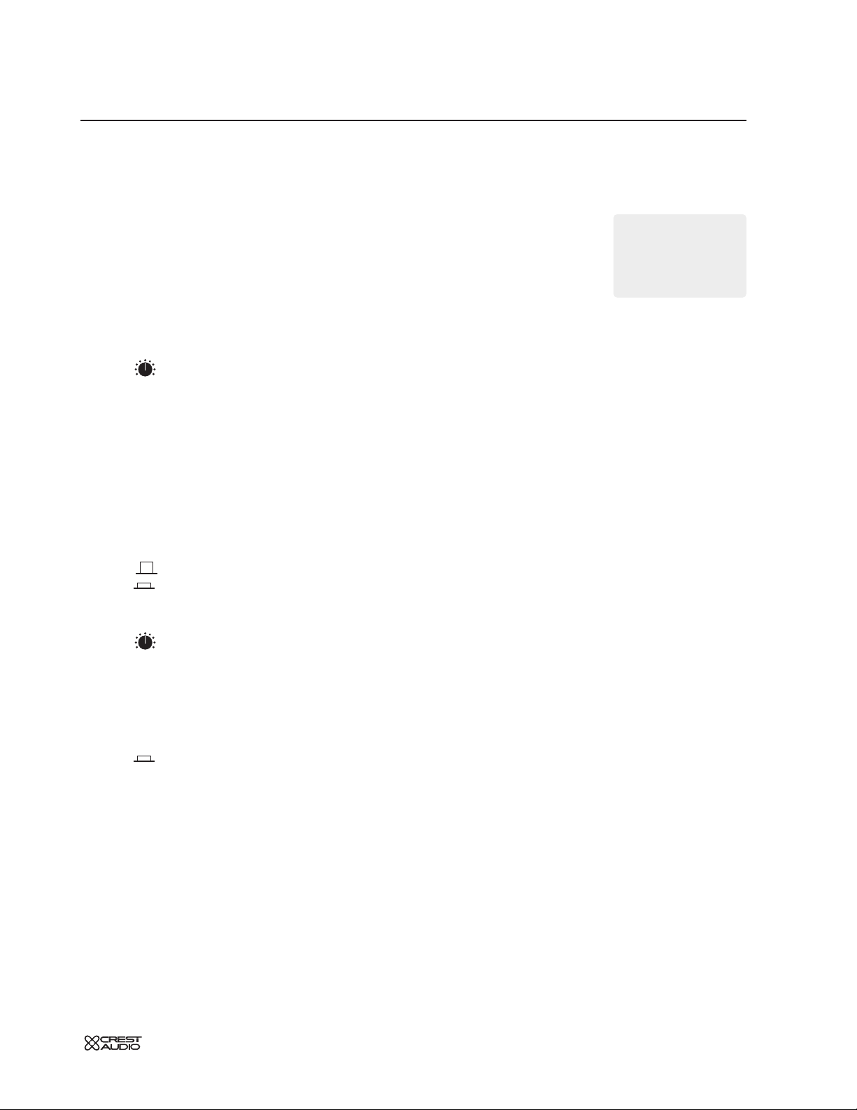
how to use this manual
format
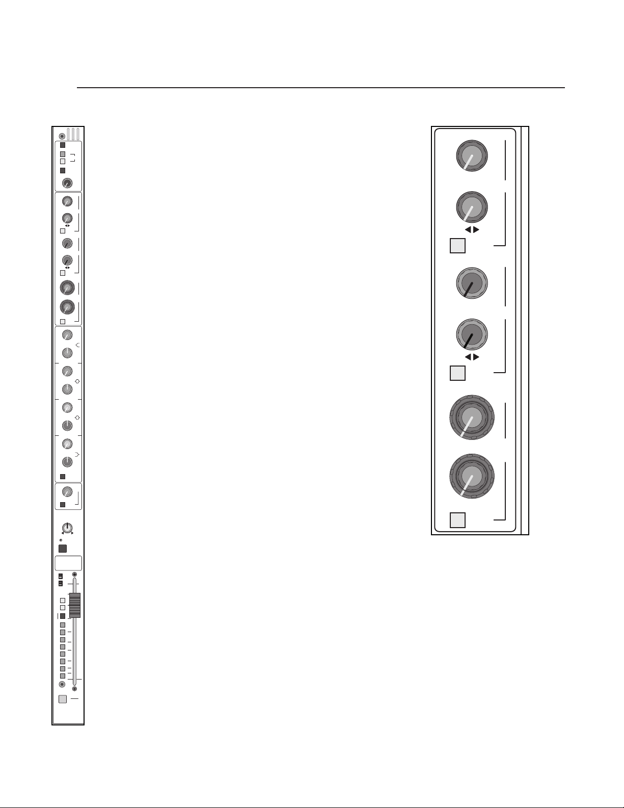
This manual uses a format that is intended to be easy to read, yet technical for those
who need to know all the details. For feature descriptions, this is done by devoting the
left side of each page to 1) an overall module picture, 2) a block diagram, and 3) a control closeup.These images all per tain to the features and control descriptions on the
right side of the page. Also, for cer tain features like the micro processor system and the
solo system that appear over and over again, references are made to sections devoted
to these features.
The intention is to make the manual easy to read while including all the technical details
needed for getting the most out of the X-VCA console, a flexible and feature-rich addition to Crest Audio's growing line of audio mixing console products.
conventions
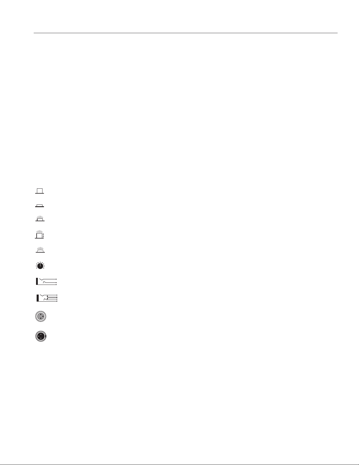
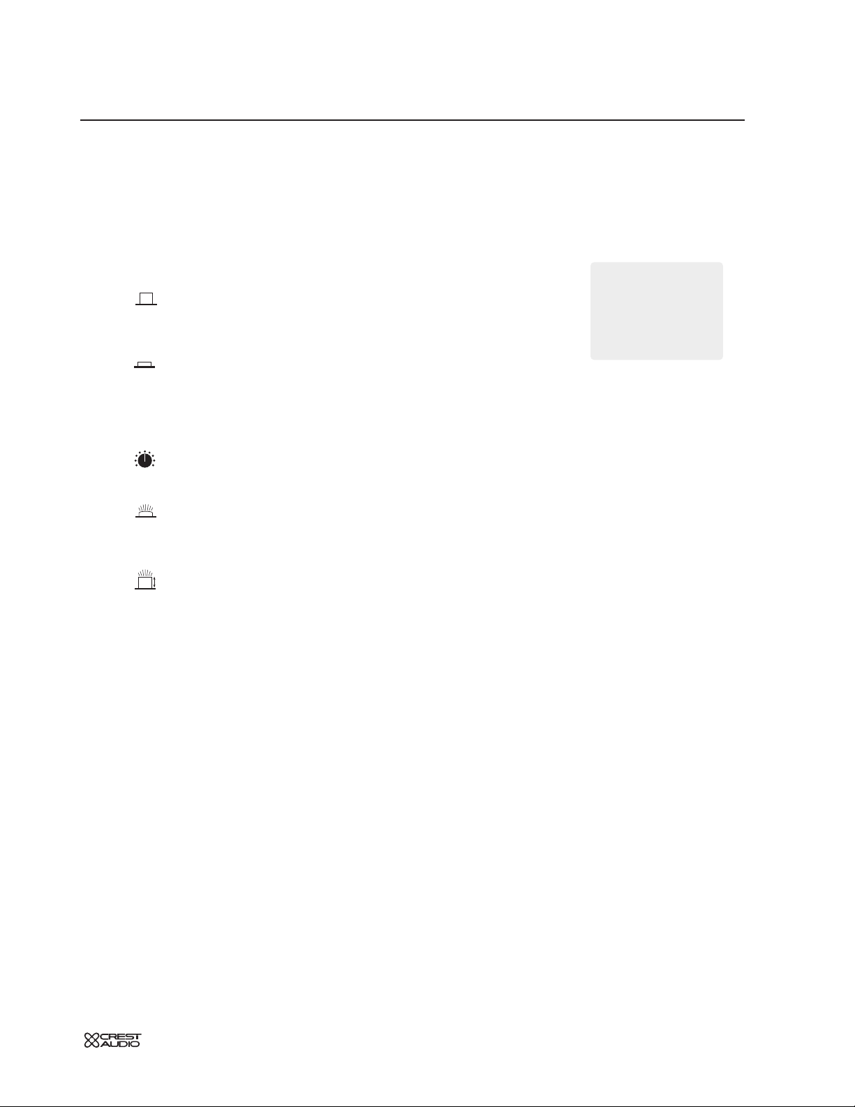
Control Icons
This manual uses little pictures, or icons to illustrate what the control descriptions are
referring to.This makes it possible to avoid redundant wording and makes the control
descriptions clear.
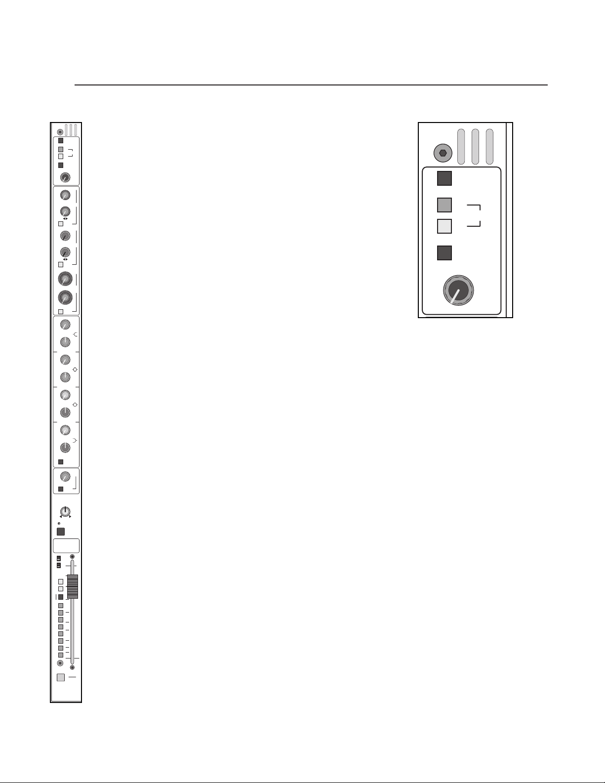
Switch in the UP, non-activated position
Switch in DOWN, activated position
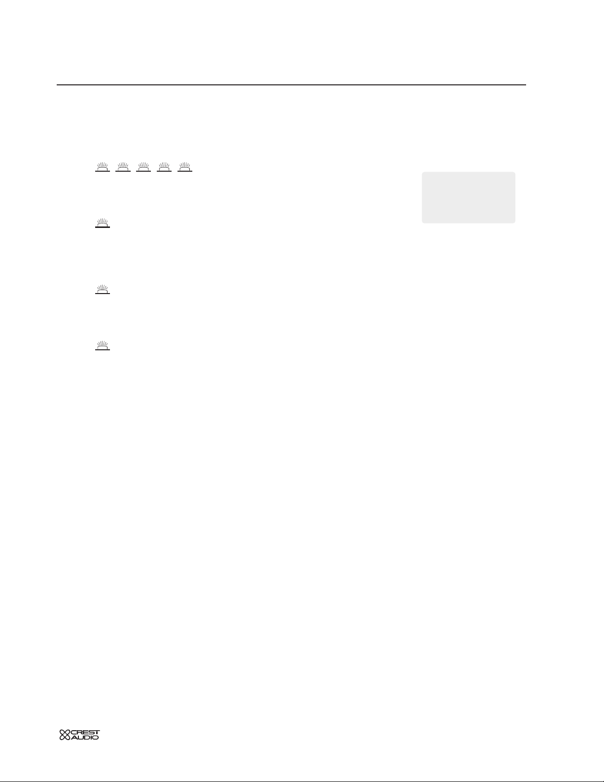
Switch that illuminates when in the DOWN position
Momentary switch that illuminates when activated
LED that is on, indicating that it's associated feature is activated
Potentiometer
Standard 1/4" TRS jack (used for line level inputs and insert sends)
1/4" TRS jack with normal switching (used on inser t returns)
Female XLR input jack
Male XLR output jack
LED
Page 6
p. 6
X-VCA owner’s manual
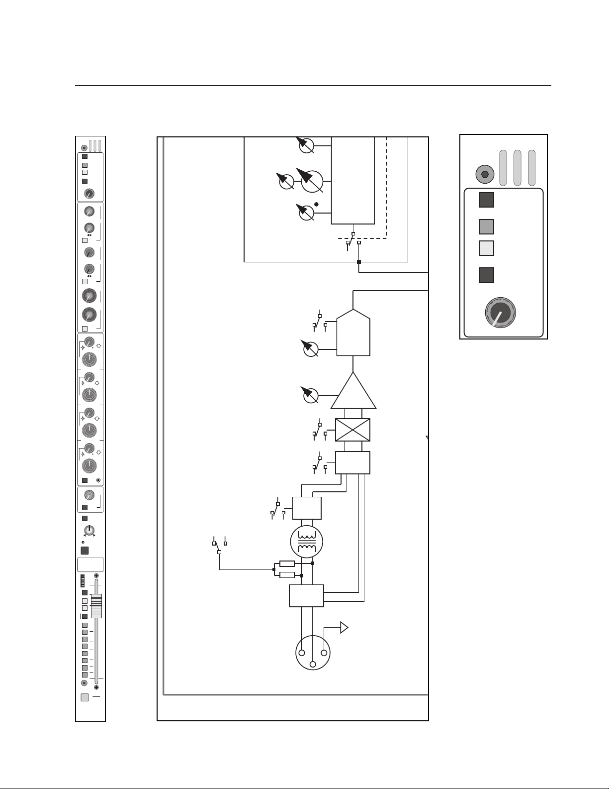
mono input module
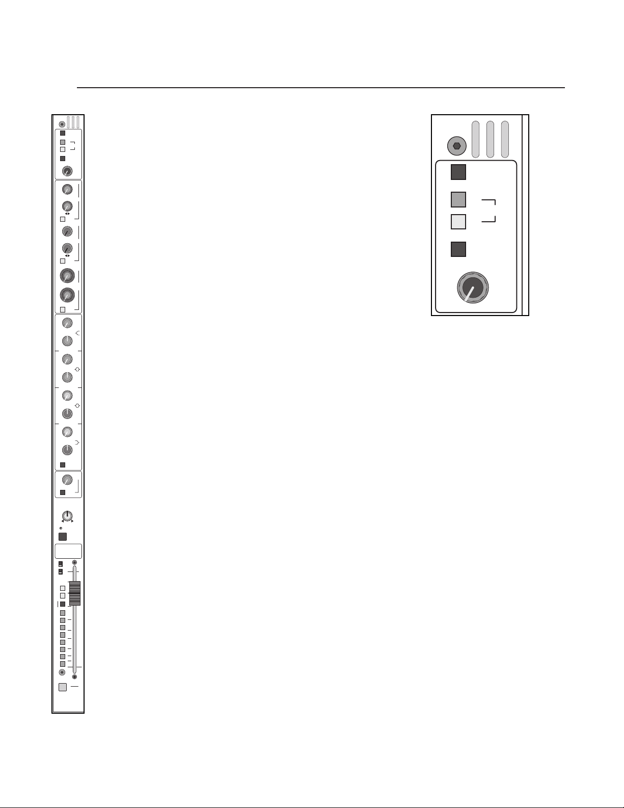
module
panel
GAIN
+
48V
PAD
LINE
Ø
30
12
20
40
50
72
block diagram
A
7
M
4
1
+
48V
PAD
LINE
Ø
GAIN
30
40
20
50
12
72
AUX
10
–
1
0
20
+
3
30
40
6
•
10
–
2
0
20
+
3
30
40
6
•
PRE
10
–
3
0
20
+
3
30
40
6
•
10
–
4
0
20
+
3
30
40
6
•
PRE
5
6
-
–
12
6
0
+
20
3
40
6
•
7
6
-
–
12
8
0
+
20
3
40
6
•
PRE
1.5
HF
Q
.7
3
SHELF
6K
3K
12K
1.5
18K
20K
1K
1.5
HM
Q
.73
2K
4K
1K
6K
8K400
1.5
LM
Q
.73
500
1K
200
1.5
2K100
1.5
LF
Q
.7
3
SHELF
200
400
100
600
80040
– +
EQ
ON
FREQ
80
200
40
20 400
HPF
INSERT
ON
C
PAN
ODD - LR - EVEN
SAFE
PREVIEW
MUTE
PK
+
8
0
–
6
10
SIG
LCR
5
M
0
L-R
PAN ON
5
GROUPS
1
10
2
3
15
4
20
5
30
6
40
7
50
8
SOLO
VCA
ASSIGN
(24 TO
X-VCA
+48V
HHF
3 - 0.
FREQ
LEVEL
QQ
3 - 0.7
HPF
400
SH
1K - 20 KHZ
HPF
20 - 400HZ
GAIN
15 - 70 DB
Ø
SW
LINE
OPTION
XFORMER
PAD
26dB
LINE
P
SW
LINE
IN
BALANCED
FOUR-B
INPUT
PREAMP
Page 7
p. 7
mono input module
features
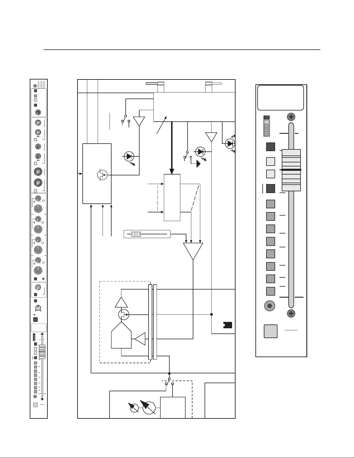
phantom power +48V
48 volts DC is applied to pins 2 and 3 on the mic-input XLR connector. This
option is used with condenser microphones and active direct boxes that require
an external DC voltage (phantom power) in order to operate.
pad
The mic-input signal is attenuated by 20dB to prevent some signals (e.g. kick
drum or lead vocal) from overloading the preamp stage.The pad is used to bring
a hot mic-input signal down to a controllable level.The 20dB pad is not functional
when the
LINE
switch is depressed.
line
The input preamp circuit is set up to accept a mic-level signal. This signal is
brought in via the XLR mic-input connector located on the rear panel.The 1/4"
TRS input jack is disabled.
The input preamp circuit is set up to accept a line-level signal from either
the XLR mic-input connector or the 1/4" TRS input jack, both located on the rear
panel.When a plug is inserted into the 1/4" TRS input jack, the XLR mic-input
connector is disabled.
polarity reverse—ø
This feature is used for correcting or minimizing polarity and phase related errors.
For example, occasionally a balanced input connection is reverse-wired before it
gets to the mixing console.This can happen in microphones, or in snake line interfaces. By using the polarity reverse feature, this type of error can be corrected.
polarity inverted
polarity not inverted
If the 48V phantom
power switch is
engaged, depressing this
switch disconnects phantom
power from the mic input
XLR.
+
1
When similar signals
from different channels are combined, phase
cancellations can occur.
Reversing the polarity of an
input signal often corrects
such phasing errors.
+
The 48V switch should
not be engaged when
using standard (dynamic)
microphones, or other
sources that do not use
phantom power.
a
Page 8
p. 8
X-VCA owner’s manual
mono input module
1
module
panel
GAIN
+
48V
PAD
LINE
Ø
30
12
20
40
50
72
block diagram
A
7
M
4
+
30
20
12
AUX
10
20
30
40
•
10
20
30
40
•
PRE
10
20
30
40
•
10
20
30
40
•
PRE
12
20
40
•
12
20
40
•
1.5
HF
3
6K
3K
1.5
1K
1.5
HM
2K
1K
1.5
LM
500
200
1.5
LF
3
200
100
80
40
20 400
C
ODD - LR - EVEN
SAFE
PREVIEW
PK
+
8
0
–
6
SIG
LCR
M
L-R
PAN ON
GROUPS
1
2
3
4
5
6
7
8
48V
PAD
LINE
Ø
72
–
6
–
6
–
6
–
6
6
6
PRE
SHELF
.73
.73
SHELF
EQ
ON
HPF
INSERT
MUTE
HHF
3 - 0.
400
FOUR-B
GAIN
40
50
1
0
+
3
2
0
+
3
3
0
+
3
4
0
+
3
5
-
–
6
0
+
3
6
7
-
–
8
0
+
3
6
Q
.7
12K
18K
20K
Q
4K
6K
8K400
Q
1K
1.5
2K100
Q
.7
400
600
80040
– +
FREQ
200
ON
PAN
10
5
0
5
10
15
20
30
40
50
(24 TO
X-VCA
+48V
FREQ
LEVEL
QQ
3 - 0.7
HPF
SH
1K - 20 KHZ
HPF
20 - 400HZ
GAIN
15 - 70 DB
Ø
LINE
OPTION
XFORMER
PAD
26dB
LINE
P
SW
LINE
IN
BALANCED
SW
INPUT
PREAMP
SOLO
ASSIGN
VCA
Page 9
p. 9
mono input module
features
gain
The Input gain control range is closely related to the status of the
PAD
switch and
the
LINE switch. In order to establish proper gain structure in the console, input
gain settings must be set correctly.
LINE—switch-up
PAD—switch-up
15 to 75dB of gain can be added the mic-input signal.
The impedance at the input XLR is 4kΩ.
LINE—switch-up PAD—switch-down
-5 to 55dB of gain can be added to the mic-input signal.
The impedance at the input XLR is 4kΩ.
LINE—switch-down PAD—switch-up or -down
-10 to 45dB of gain can be added the line-input signal.
The impedance at the input XLR and input 1/4" TRS is 20kΩ.
1
If the channel peak
LED is illuminated,
first try lowering
the input gain control.
Only when this method is
unsuccessful should the pad
switch be engaged.
+
Page 10
1
p. 10
X-VCA owner’s manual
mono input module
module
panel
PRE
PRE
AUX
PRE
5
-
6
3
4
7
-
8
1
2
40
12
6
0
6
•
3
20
+
–
40
12
6
0
6
•
3
20
+
–
40
20
10
0
6
•
3
30
+
–
40
20
10
0
6
•
3
30
+
–
40
20
10
0
6
•
3
30
+
–
40
20
10
0
6
•
3
30
+
–
block diagram
SAFE
LEGENDS
C
T
A
A
O
C
20
AUX
30
30
30
30
20
40
20
40
HF
3K
1.5
HM
1K
LM
200
LF
100
40
ODD - LR - EVEN
LCR
M
L-R
PAN ON
GROUPS
1
2
3
4
5
6
7
8
30
12
20
40
•
20
40
•
20
40
•
20
40
•
12
•
12
•
3
1K
500
3
200
80
20 400
SIG
10
10
10
10
2K
PREVIEW
PK
+
–
1.5
6K
1.5
1.5
1.5
8
0
6
+
48V
PAD
LINE
Ø
PRE
PRE
6
6
PRE
SHELF
SHELF
EQ
ON
HPF
INSERT
C
SAFE
72
–
–
–
–
.73
.73
MUTE
6
6
6
6
ON
SOLO
ASSIGN
F
C
MI
IN
GR
TO
INPUT
1-2 LEV/PAN CTRL
3- LEV
PRE
AMP
MICRO
AUX 3
4 - PAN
PRE-FADER
CARDS
AUX 4
3-4 LEV/PAN CTRL
POST-FADER
AUX 6
AUX 5
5- LEV
6 - PAN
5-8
PRE
AFL MODE
SOLO LEFT
MODULE
CIRCUITS
1 THRU 4
1 - LEV
1-2
PRE
YES
NO
EQ FDR
SOLO RIGHT
AUX 2
AUX 1
2 - PAN
3-4
PRE-SOURCE
PRE
SELECT
SOURCE
GAIN
40
50
1
0
+
3
2
0
+
3
3
0
+
3
4
0
+
3
5
-
–
6
0
+
3
6
7
-
–
8
0
+
3
6
Q
.7
12K
18K
20K
Q
4K
6K
8K400
Q
1K
1.5
2K100
Q
.7
400
600
80040
– +
FREQ
200
PAN
10
5
0
5
10
15
20
30
40
50
PREV
FROM
1 OF 4
PREVIEW
AUX SENDS
MUTE ?
FROM
5-6 LEV/PAN CTRL
7- LEV
OBE
XLR
1/4” TRS
1
CIR
CARD
MICRO
MASTER
AUX 7
8 - PAN
FRANK
JACK
JACK
AUX 8
7-8 LEV/PAN CTRL
TO SOLO
PRE-EQ
ELECT
VCA
SOURCE
DIRECT OUT
SWITCH
AT 0 VU
CH
TPUT, PIN 1 FOR GND
TS (XLR JACKS)
Page 11
p. 11
mono input module
1
aux send features
Eight auxiliary sends are available for creating individual output mixes. These can
be used to drive effects processors, provide monitor mixes, create broadcast or
alternate sound reinforcement mixes, or for other special requirements. Each pair
of odd/even Aux buses (1&2, 3&4, etc.) can be treated as individual discrete mono
sends, or as stereo pairs. Discrete mono or stereo pair mods are selected globally for each aux pair via mode switched in the Aux master section, located at the
top of the Group modules.
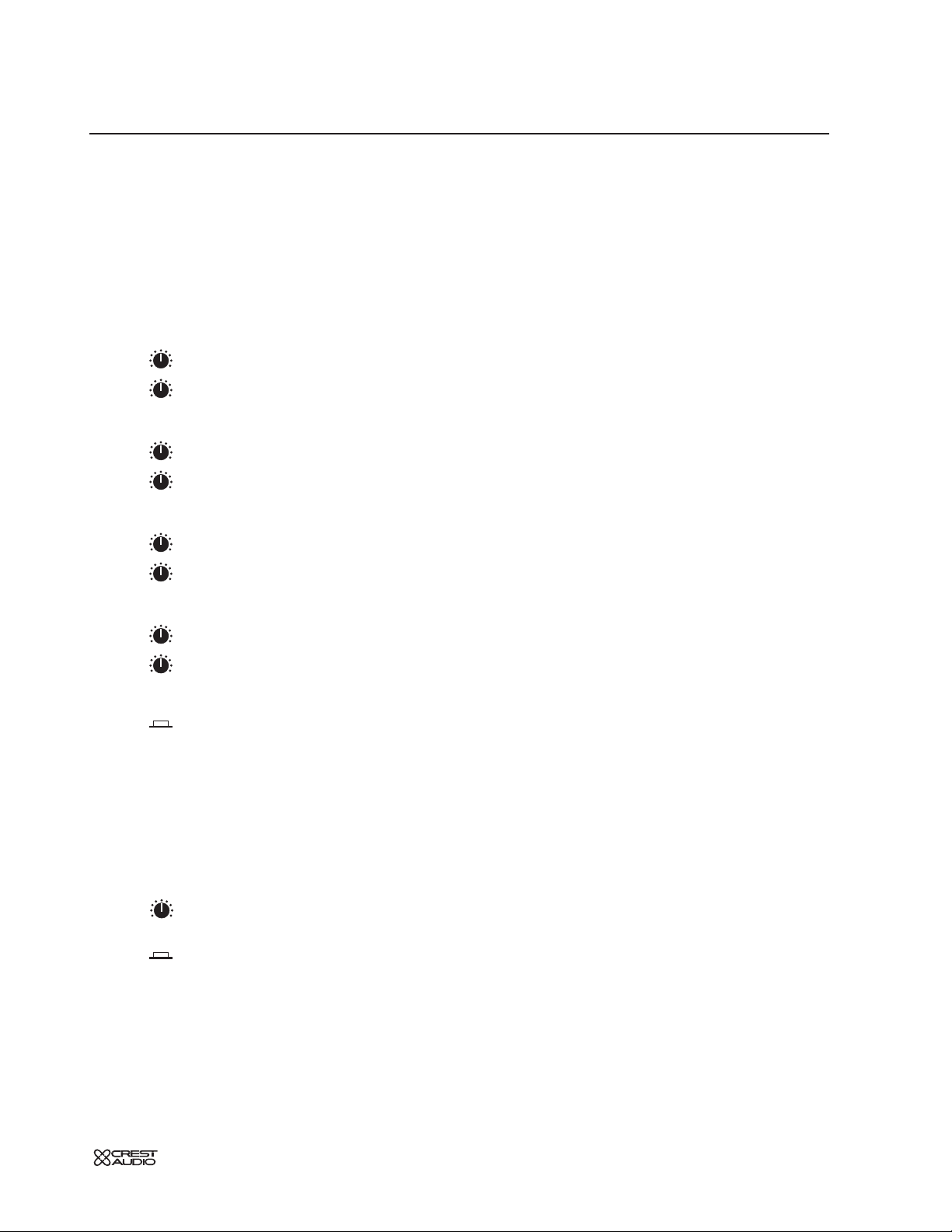
Aux sends 1-2,3-4
These knobs adjust the amount of signal sent to the first four AUX buses.
Unity gain occurs at the he zero setting.
In mono mode, each control independently determines the send level for the
respective aux mix. When stereo mode is selected, the top (odd numbered) control sets signal level while the bottom (even numbered) control pans the signal
between odd and even auxiliary mix buses (odd = left, even = right).
Aux PRE switches 1-2, 3-4,
The Aux PRE switches determine the source for each pair of AUX sends.The signal that these switches use for the PRE setting can be further defined by changing
the position of a couple of internal jumpers. See INTERNAL JUMPER
OPTIONS.
AUX SENDS are post-insert, post-eq, post-mute, post-fader
AUX SENDS are post-insert, post-eq, post-mute, pre-fader
Aux sends 5-6,7-8 (Dual Concentric)
In mono mode, the inner knobs control levels for aux 5 and 7, respectively.
The outer knobs control levels for aux 6 and 8, respectively. When stereo mode
is selected for either of the odd/even aux pairs, the center knobs become the
level controls and the outer knobs become the pan controls.
Aux 5-6 & 7-8 PRE switch
See "Aux PRE switches 1-2, 3-4" above.This button functions the same
way, however it selects the signal source for Aux's 5,6, 7 & 8.
It's typical to
make Aux sends
Post fader when driving
effects, and Pre fader when
mixing for monitors.
+
Page 12
1
p. 12
X-VCA owner’s manual
mono input module
module
panel
EQ
ON
FREQ
1.5
1.5
SHELF
SHELF
LF
LM
HM
HF
– +
.7
3
Q
3K
6K
12K
20K
1K
18K
1.5
1K
2K
4K
8K400
6K
1.5
.73
Q
1K
2K100
1.5
200
500
400
80040
600
10 0
200
1.5
.73
Q
.7
3
Q
block diagram
C
30
20
AUX
20
30
40
20
30
40
20
30
40
20
30
40
12
20
40
12
20
40
HF
3K
1.5
1K
HM
1K
LM
500
200
LF
200
100
80
40
20 400
ODD - LR - EVEN
12
•
•
•
•
•
•
3
3
10
10
10
10
1.5
6K
1.5
2K
1.5
1.5
PREVIEW
+
48V
PAD
LINE
Ø
PRE
PRE
6
6
PRE
SHELF
SHELF
EQ
ON
HPF
INSERT
C
SAFE
72
–
–
–
–
.73
.73
MUTE
YES
GAIN
40
50
1
0
+
3
6
2
0
+
3
6
3
0
+
3
6
4
0
+
3
6
5
-
–
6
0
+
3
6
7
-
–
8
0
+
3
6
Q
.7
12K
18K
20K
Q
4K
6K
8K400
Q
1K
1.5
2K100
Q
.7
400
600
80040
– +
FREQ
200
VCA SUB-
VCA
FREQ
LEVEL
Q
FREQ
LEVEL
Q
FREQ
LEVEL
Q
3 - 0.7 3 - 0.7
3 - 0.7
EQ
ON
SH
LF
40 - 800 HZ
LOW MIDHI MIDHF
400 - 8 KHZ 100 - 2 KHZ
PRE
MUTE ?
SOURCE
PEAK+80-6SIG
INPUT METER
NO
FOUR-BAND FULLY PARAMETRIC EQ
FREQ
ON
PAN
LEVEL
Q
3 - 0.7
SH
1K - 20 KHZ
PK
+
8
0
–
6
LCR
M
L-R
PAN ON
GROUPS
1
2
3
4
5
6
7
8
SIG
SOLO
ASSIGN
10
5
0
5
10
15
20
30
40
50
VCA
HPF
20 - 400HZ
70 DB
AIN
HPF
AMP
PUT
ON
INSERT
Page 13
p. 13
mono input module
1
EQ features
Many audio signals coming into the console require some degree of corrective eq
in order to be part of a good sounding mix.The X-VCA offers an uncompromised, full parametric EQ on each channel.
The input EQ consists of four full parametric bands: high, high-mid, low-mid, and
low. The high and low bands are independently switchable for either adjustable
bandwidth or shelving mode. All bands offer a generous overlap of adjacent operating frequencies. An independent, variable high pass filter provides additional
problem-solving flexibility.
high frequency—HF
Bandwidth A Q range of 3.0 to 0.7 (0.5 octave to 2.0 octave) is available.
Turning the control full clockwise switches operation to a plus/minus shelving
mode.
Boost / Cut (inner knob)15dB boost and cut.
Frequency (outer knob) Continuously sweepable between 1kHz and
20kHz
high mid—HM
Bandwidth A Q range of 3.0 to 0.7 (0.5 octave to 2.0 octave) is available.
Boost / Cut (inner knob)15dB boost and cut.
Frequency (outer knob) Continuously sweepable between 400 Hz and 8
kHz.
Low mid—LM
Bandwidth A Q range of 3.0 to 0.7 (0.5 octave to 2.0 octave) is available.
Boost / Cut (inner knob)15dB boost and cut.
Frequency (outer knob) Continuously sweepable between 100 Hz and 2
kHz.
Low frequency—LF
Bandwidth A Q range of 3.0 to 0.7 (0.5 octave to 2.0 octave) is available.
Turning the control full clockwise switches operation to a plus/minus shelving
mode.
Boost / Cut (inner knob)15dB boost and cut.
Frequency (outer knob) Continuously sweepable between 40 Hz and 800
kHz.
eq on
Equalizer is on. This switch is used to activate the EQ section and can be
used to make A/B comparisons between "flat" and eq'd signals.
When boosting or cutting EQ, it is often
necessary to compensate
for cumulative level
changes. This is best done
with the Input Gain control
+
Page 14
1
p. 14
X-VCA owner’s manual
mono input module
module
panel
20 400
40
80
200
EQ
ON
FREQ
SHELF
HPF
PAN
INSERT
ON
C
– +
400
80040
600
10 0
200
.7
3
block diagram
E
(24
TO
48
FITTED)
+
48V
PAD
LINE
Ø
GAIN
30
40
20
50
12
72
AUX
10
–
1
0
20
+
3
30
40
6
•
10
–
2
0
20
+
3
30
40
6
•
PRE
10
–
3
0
20
+
3
30
40
6
•
10
–
4
0
20
+
3
30
40
6
•
PRE
5
6
-
–
12
6
0
+
20
3
40
6
•
7
6
-
–
12
8
0
+
20
3
40
6
•
PRE
1.5
HF
Q
.7
3
SHELF
6K
3K
12K
1.5
18K
20K
1K
1.5
HM
Q
.73
2K
4K
1K
6K
8K400
1.5
LM
Q
.73
500
1K
200
1.5
2K100
1.5
LF
Q
.7
3
SHELF
200
400
100
600
80040
– +
EQ
ON
FREQ
80
200
40
20 400
HPF
INSERT
ON
C
PAN
ODD - LR - EVEN
SAFE
PREVIEW
MUTE
PK
+
8
0
–
6
10
SIG
LCR
5
M
0
L-R
PAN ON
5
GROUPS
1
10
2
3
15
4
20
5
30
6
40
7
50
8
SOLO
VCA
ASSIGN
+48V
FREQ
LEVEL
FREQ
LEVEL
FREQ
LEVEL
PAD
26dB
Q
3 - 0.7
Q
3 - 0.7
Q
3 - 0.7
HPF
20 - 400HZ
GAIN
15 - 70 DB
Ø
LINE
P
SW
LINE
LOW MIDHI MIDHF
400 - 8 KHZ 100 - 2 KHZ
SH
1K - 20 KHZ
LINE
OPTION
XFORMER
FOUR-BAND FULLY PARAMETRIC
HPF
INPUT
SW
P
+80-6SIG
INPUT METER
INSERT
PREAMP
GC
Page 15

p. 15
1
high-pass filter—HPF
Proper use of the high-pass filter reduces or eliminates unwanted low frequencies
without substantially affecting the program material. Quite often such unwanted
low frequencies are included with in-coming mic- or line-input signals. For example, stage rumble or wind can be picked up through vocal mics.The slope of the
high-pass filter is 12dB per octave.
HPF
High-pass filter is on.
HPF—variable control
When the high-pass filter is on, this control selects a frequency between
20Hz and 400Hz as the point where attenuation begins.
mono input module
Many microphones
have a built-in switchable high-pass filter.
+
Page 16
1
p. 16
X-VCA owner’s manual
mono input module
module
panel
20 400
40
80
200
EQ
ON
FREQ
HPF
ODD - LR - EVEN
PAN
INSERT
ON
SAFE
PREVIEW
C
– +
80040
600
block diagram
Y
U
20
AUX
30
30
30
30
20
40
20
40
HF
3K
1.5
HM
1K
LM
200
LF
100
40
ODD - LR - EVEN
LCR
M
L-R
PAN ON
GROUPS
1
2
3
4
5
6
7
8
30
12
10
20
40
•
10
20
40
•
10
20
40
•
10
20
40
•
12
•
12
•
3
1K
2K
500
3
200
80
20 400
PREVIEW
PK
+
–
SIG
+
48V
PAD
LINE
Ø
GAIN
40
50
72
–
0
+
3
6
–
0
+
3
6
PRE
–
0
+
3
6
–
0
+
3
6
PRE
6
–
6
6
–
6
PRE
1.5
.7
SHELF
6K
12K
20K
1.5
.73
4K
8K400
1.5
.73
1K
2K100
1.5
.7
SHELF
400
80040
EQ
ON
200
HPF
INSERT
ON
C
SAFE
MUTE
8
0
6
INP
-6SIG
HI MIDHF
400 - 8 KHZ1K - 20 KHZ
1
2
3
4
5
-
6
0
+
3
7
-
8
0
+
3
Q
18K
Q
SH
FOUR-BAND FULL
PRE
FADER
POST
FADER
ON
INSERT
HPF
6K
Q
1.5
Q
600
– +
FREQ
LINE
PAN
10
5
0
5
10
15
20
30
40
50
OPTION
XFORMER
SW
INPUT
PREAMP
GC
GC
SOLO
ASSIGN
VCA
INSERT SEND
BAL INSERT RTN
DIRECT OUT
Page 17
p. 17
mono input module
1
Insert features
Insert ON switch
The Insert point is located after the EQ and before the Low Pass Filter.
External signal processors can be inserted into the channel via 1/4" TRS
connectors (send and return) on the rear panel.The SEND signal is unbalanced and the RETURN can accept both unbalanced and balanced signals.
Insert is switched OUT. Any signal coming into the Insert RETURN
jack is left unused.The Insert SEND jack can be used to derive a post-EQ,
pre-LPF output from the channel without interrupting the channel's normal
signal flow.
Insert is switched IN.The Insert RETURN jack is activated.The
RETURN jack can also be used as an input for situations where the mic
preamp and it's associated features are not required, such as when using an
external mic preamp.
pan control
See description of Bus Assignment features later in this section
safe preview
Safe Preview LED
See LOCAL MICROPROCESSOR CONTROL section
mute
Mute switch
See LOCAL MICROPROCESSOR CONTROL section
write-in label
This label may be written on with a grease-marker, or dry-erase pen and later
wiped clean. Masking tape may also be placed on this surface, if desired. If you
write on it with a "Sharpie", you may have trouble getting the writing off. If this is
the case, your best bet is to wipe the label off with isopropyl (rubbing) alcohol.
If you are using a
something like an
external tube mic preamp,
you can bypass the channel's input preamp by coming into the insert return
jack.
+
LED
Page 18
1
p. 18
X-VCA owner’s manual
mono input module
module
panel
LCR
1
2
3
4
5
6
7
8
M
L-R
PAN ON
GROUPS
PK
–
6
0
SIG
+
8
5
10
0
5
10
20
30
15
50
40
SOLO
VCA
ASSIGN
block diagram
C
+
48V
PAD
LINE
Ø
GAIN
30
40
20
50
12
72
AUX
10
–
1
0
20
+
3
30
40
6
•
10
–
2
0
20
+
3
30
40
6
•
PRE
10
–
3
0
20
+
3
30
40
6
•
10
–
4
0
20
+
3
30
40
6
•
PRE
5
6
-
–
12
6
0
+
20
3
40
6
•
7
6
-
–
12
8
0
+
20
3
40
6
•
PRE
1.5
HF
Q
.7
3
SHELF
6K
3K
12K
1.5
18K
20K
1K
1.5
HM
Q
.73
2K
4K
1K
6K
8K400
1.5
LM
Q
.73
500
1K
200
1.5
2K100
1.5
LF
Q
.7
3
SHELF
200
400
100
600
80040
– +
EQ
ON
FREQ
80
200
40
20 400
HPF
INSERT
ON
C
PAN
ODD - LR - EVEN
SAFE
PREVIEW
MUTE
PK
+
8
0
–
6
10
SIG
LCR
5
M
0
L-R
PAN ON
5
GROUPS
1
10
2
3
15
4
20
5
30
6
40
7
50
8
SOLO
VCA
ASSIGN
400 - 8 KHZ 100 - 2 KHZ1K - 20 KHZ 40 - 800 HZ
FOUR-BAND FULLY PARAMETRIC EQ
HPF
T
MP
PRE
MUTE ?
SOURCE
PEAK+80-6SIG
INPUT METER
YES
NO
INSERT
ON
EQ FDR
PRE
PRE
FADER
AMP
PRE-SOUR
SELECT
SOURCE
PRE-EQ
POST
PRE-FADER
POST-FADER
SOURCE
DIRECT OUT
FADER
Page 19
p. 19
mono input module
level meter features
level meter
Each input includes a five-segment LED meter for visually monitoring signal levels.This is essential for setting up and maintaining proper
gain structure.
peak indicator—PK
The input signal is monitored at several points throughout the channel.
These points are the mic preamp, the EQ stage and the fader stage. Overloads at
any of these stages will cause the red peak-LED to light.
Then the channel gain should reduced.
signal level LED’s
These three LED's light up at +8—yellow, 0—green, and -6 dB—green.This
level range -6 to +8 is the optimum operating range. Compressed or relatively
constant signals should remain close to 0.
signal present indicator—SIG
This green-LED varies in brightness in response to signal levels between -40
dB and -6 dB.
Occasional flashing of the
peak LED is acceptable,
but frequent flashes indicate that channel levels
must be lowered.
®
1
LEDLEDLEDLEDLED
LED
LED
LED
Page 20
1
p. 20
X-VCA owner’s manual
mono input module
module
panel
ODD - LR - EVEN
PAN
MUTE
SAFE
PREVIEW
C
LCR
1
2
3
4
5
6
7
8
M
L-R
PAN ON
GROUPS
PK
–
6
0
SIG
+
8
5
10
0
5
10
20
30
15
50
40
SOLO
VCA
ASSIGN
block diagram
8
PAN
20
AUX
20
30
20
30
20
30
20
30
12
20
40
12
20
40
HF
3K
1.5
HM
1K
LM
200
LF
100
40
ODD - LR - EVEN
LCR
M
L-R
PAN ON
GROUPS
1
2
3
4
5
6
7
8
+
48V
PAD
LINE
Ø
30
12
72
10
–
40
•
10
–
40
•
PRE
10
–
40
•
10
–
40
•
PRE
6
•
6
•
PRE
1.5
3
SHELF
6K
1K
1.5
.73
2K
1.5
.73
500
1.5
3
SHELF
200
EQ
ON
80
20 400
HPF
INSERT
C
SAFE
PREVIEW
MUTE
PK
+
8
0
–
6
SIG
6
6
6
6
ON
SOLO
ASSIGN
GAIN
40
50
1
0
+
3
2
0
+
3
3
0
+
3
4
0
+
3
5
-
–
6
0
+
3
6
7
-
–
8
0
+
3
6
Q
.7
12K
18K
20K
Q
4K
6K
8K400
Q
1K
1.5
2K100
Q
.7
400
600
80040
– +
FREQ
200
PAN
-
AUX 8
7-8 LEV/PAN CTRL
TO SOLO
BUS ASSIGN
& CONTROL
MONO L-R 1357
L- AFL -R
SWITCHING
PA N
SWITCHES
2468
LCR PAN
X-VCA STEREO INPUT
(4 NORMALLY FITTED)
10
5
10
15
20
30
40
50
0
5
LEGENDS
VCA
1 FOR GND
ACKS)
OLO R
Page 21
bus assignment features
The Input bus assignment section offers considerable flexibility for creating what
eventually becomes the main output mix. Such features as
LCR, GROUP PAN ON
and
eight-individual group assignments allow several approaches to building the
desired mix.All assignments are derived post-fader, post-eq, and post-mute.
pan control
The pan control positions the signal within the stereo left/right field,
(or between left/center or center/right in
LCR mode).The signal must be assigned
to either LCR or the L-R bus for the pan control to have any affect.
left-center -right—LCR
This feature is used to precisely position a signal in a sound system with a center
speaker cluster in addition to left and right clusters.The PA N control becomes an
integral part of how the input-signal is sent to the LEFT, CENTER, and RIGHT outputs.
The post-fader signal is assigned to the LEFT, RIGHT, and MONO/CENTER buses.
Relative amounts of the signal fed to each bus is determined by the position of
the PA N control.
mono assignment—M
The signal is assigned to the discrete mono bus.
When the LCR button is depressed, this switch is bypassed.
left / right assignment—L-R
The Input signal is assigned to the main Left and Right output buses, deriving
its signal after the channels pan system.When the LCR button is depressed, this
switch is bypassed.
pan on—groups—PAN ON
The eight GROUP assignment switches assign the input signal in mono, independent of the pan pot.
The eight GROUP assignment switches assign signals as four stereo-pairs.The
PAN
control governs the stereo placement of the four stereo-pairs, which are now
configured as odd–left / even–right.
For example: GROUP 1—left, GROUP 2—right, GROUP 3—left, GROUP 4—right, ...con-
tinuing through GROUP 8.
group 1–8 assignment
The input channel's post-fader signal is assigned to the corresponding GROUP
bus(es). see—pan on—groups
mono input module
1
If the channel's
Left/Right signal goes
way when the Pan pot is at
center, check to see if the
LCR button is down.
+
Page 22
p. 22
X-VCA owner’s manual
mono input module
1
module
panel
LCR
1
2
3
4
5
6
7
8
M
L-R
PAN ON
GROUPS
PK
–
6
0
SIG
+
8
5
10
0
5
10
20
30
15
50
40
SOLO
VCA
ASSIGN
block diagram
O
E
MOD
O
X
U
+
48V
PAD
LINE
Ø
GAIN
30
40
20
50
12
72
AUX
10
–
1
0
20
+
3
30
40
6
•
10
–
2
0
20
+
3
30
40
6
•
PRE
10
–
3
0
20
+
3
30
40
6
•
10
–
4
0
20
+
3
30
40
6
•
PRE
5
6
-
–
12
6
0
+
20
3
40
6
•
7
6
-
–
12
8
0
+
20
3
40
6
•
PRE
1.5
HF
Q
.7
3
SHELF
6K
3K
12K
1.5
18K
20K
1K
1.5
HM
Q
.73
2K
4K
1K
6K
8K400
1.5
LM
Q
.73
500
1K
200
1.5
2K100
1.5
LF
Q
.7
3
SHELF
200
400
100
600
80040
– +
EQ
ON
FREQ
80
200
40
20 400
HPF
INSERT
ON
C
PAN
ODD - LR - EVEN
SAFE
PREVIEW
MUTE
T
NE
MOD
AND
VCA,
SOLO LEFT
SOLO RIGHT
VCA
SOLO
ASSIGN
MUTE
CTRL
SOLO
FR
PR
1 OF 4
MUTE
CARD
MICRO
INTERFACE
INPUT CHAN
SAFE
PREVIEW
& SWITCHING
SOLO CONTROL
BUSES 1-8
VCA MASTER
LATCHES
VCA ASSIGN
AUX SENDS
PRE-FADER
POST-PAN
L - R
FADER
CHANNEL
CV
LCR
M
L-R
PAN ON
GROUPS
PK
+
8
0
–
6
10
SIG
5
0
5
1
10
2
3
15
4
20
5
30
6
40
7
50
8
SOLO
VCA
ASSIGN
VCA SUB-CARD
VCA
FREQ
LEVEL
EQ
ON
F
00 HZ
PRE
MUTE ?
SOURCE
Page 23

p. 23
mono input module
When VCA faders
become dirty or worn,
they do not become noisy
because there's no audio
going through them.
+
1
features
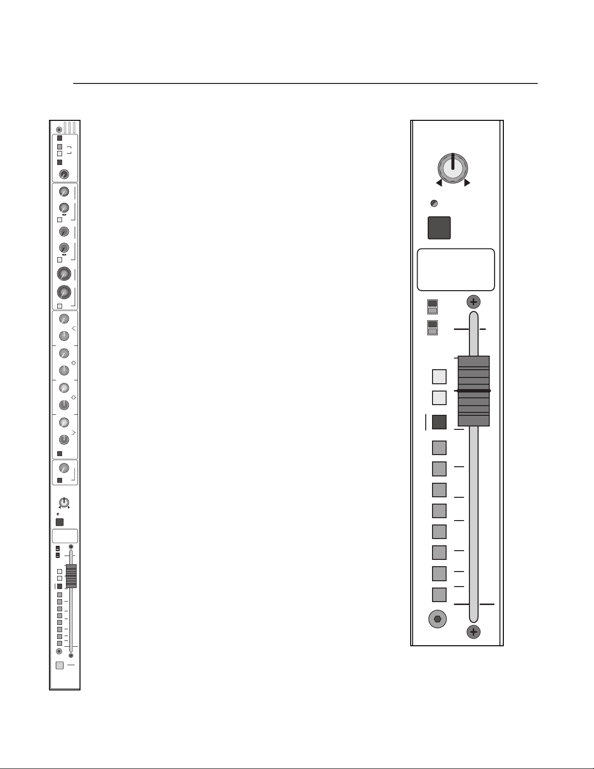
input fader
The input fader is the primary level control for signals being sent to any of the
consoles mix buses.The signals affected are the AUX sends selected to be prefader.The fader offers greater than 80dB of attenuation and up to 10dB of boost .
Normal operation is between -10 and 0.
The fader itself is a 100mm 10K linear taper slide potentiometer. It controls the
voltage to the channel's VCA. No audio passes through the fader.
solo switch
Pressing this momentary switch will include (illuminate) or exclude (not-illu-
minated) the channel from the consoles solo system.
See SOLO / VCA Edit switch section.
Page 24
block diagram
1
p. 24
X-VCA owner’s manual
mono input module
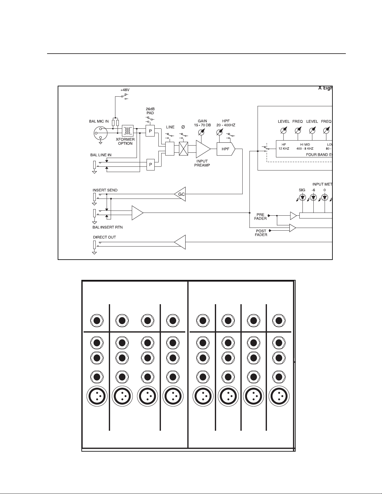
module rear
Direct
Out
I
n
s
e
r
t
Bal Line In Bal Line In Bal Line In Bal Line In
Bal Mic In Bal Mic In Bal Mic In Bal Mic In
Direct
Out
S
e
I
n
n
d
s
e
R
e
r
t
t
u
r
n
Direct
Out
S
e
n
d
R
e
t
u
r
n
S
e
I
n
s
e
r
t
I
n
n
d
s
e
R
e
r
t
t
u
r
n
Direct
Out
Direct
Out
S
e
I
n
n
d
s
e
R
e
r
t
t
u
r
n
Direct
Out
S
e
I
n
n
d
s
e
R
e
r
t
t
u
r
n
Direct
Out
S
e
I
n
n
d
s
e
R
e
r
t
t
u
r
n
Bal Line In Bal Line In Bal Line In Bal Line In
Bal Mic In Bal Mic In Bal Mic In Bal Mic In
Direct
Out
S
e
n
d
R
e
t
u
r
n
S
e
I
n
n
d
s
e
R
e
r
t
t
u
r
n
Page 25
2
p. 25
mono input module
rear panel features
direct out 1/4" TRS jack
The input channel's signal is available at this output jack.The default signal routing is derived post-fader, post-eq and post-mute.This output jack is
ground-compensated.
inser
t points
Separate 1/4" TRS jacks provide the facilities for inserting an external signal
processor into the signal path of the input channel.
insert send
This jack serves as an output for connection to the input of a signal
processor.The signal is derived after the mic preamp and HPF but before the eq
section. Plugging a 1/4" TRS plug into this jack does not break the signal flow of
the channel.This output jack is ground-compensated.
insert return
The output of a signal processor is fed to this jack. It can accept a balanced or unbalanced signal and is located pre-eq. Plugging a 1/4" TRS plug into this
jack breaks the signal flow of the channel.
balanced line-in jack—Bal Line In
Line-level signals, balanced or unbalanced, may be brought into the
input channel through this jack.The
LINE switch must be depressed for this jack to
be active.
balanced mic-in xlr connector—Bal Mic In
This balanced female XLR accepts a low-impedance microphone signal, or
a line-level signal, depending on position of the
LINE switch on the front panel.
see—mono input module, phantom power, line
Page 26
2
p. 26
X-VCA owner’s manual
stereo input module
GAIN
PRE
PRE
AUX
1
2
3
4
5
6
7
8
PK
SIG
L
R
ODD - LR - EVEN
BAL
STEREO INPUT
MUTE
SAFE
PREVIEW
=
HPF
20 400
40
80
200
EQ
ON
PRE
5
6
3
4
7
8
1
2
600
1K
2K
3K
8K
400
5K
LF
LM
HM
HF
150
500
1K
2K
100
60
400
800
40
M
L-R
BAL ON
GROUPS
40
12
6
0
6
•
3
20
+
–
40
12
6
0
6
•
3
20
+
–
40
20
10
0
6
•
3
30
+
–
40
20
10
0
6
•
3
30
+
–
40
20
10
0
6
•
3
30
+
–
40
20
10
0
6
•
3
30
+
–
3K
6K
12K
20K
1K
18K
1.5
15
6
0
6
25
10
3
+–
0
1515
88
+–
0
1515
88
+–
0
1515
88
+–
0
1515
88
+–
5
10
0
5
10
20
30
15
50
40
SOLO
VCA
ASSIGN
LINE 2
Ø
MONO
L
R
GAIN
15
6
0
6
25
10
3
+–
LINE 2
Ø
MONO
L
R
Page 27
2
p. 27
stereo input module
features
The Stereo Input Module can be configured to accept either a stereo pair of signals or a standard mono signal. Unlike the Mono Input module, the Stereo input
modules do not have mic preamps and their associated features (48 V phantom
power and PAD). Instead, the Stereo Input module accepts line level signals via
multiple pairs of input connectors - RCA, 1/4" TRS and Female XLR.When configured as a Stereo Module, the Left and Right signals are kept separate throughout
the module. Settings in the EQ section apply equally to both L & R signals.
Input signal switching
There are six Input connectors on the back of the module - three stereo pairs.
The primary pair of connectors are Female XLR.This Left / Right pair makes up
"Balanced Line In 1".The secondary connectors are 1/4" balanced TRS and unbalanced RCA. These connectors make up "Line In 2".The TRS connectors override the RCA connectors.
Line select - Line 2 switch
The channel is in LINE 1 MODE.The signals are brought in via the left and
right line-input XLRs located on the rear panel.
The channel is in LINE 2 MODE.The signals are brought in via the RCA line
input connectors which are normalled through the 1/4" TRS line-input jacks.
Insertion of a plug into the 1/4" jack disconnects it's associate RCA jack.
left and right mono-switches
These switches provide several options for configuring the stereo line-input module as a mono line-input module.
left right
Signals brought into the left and right inputs are treated as stereo throughout the
module.
left right
Signals brought into the left and right inputs are summed together immediately
before the
GAIN control.The summed signal is treated as mono throughout the
rest of the module.
left right
The signal fed to the left input is treated as a mono signal throughout the module.
No signal from the right input is used.
left right
The signal fed to the right input is treated as a mono signal throughout the module. No signal from the left input is used.
Page 28
p. 28
stereo input module
2
X-VCA owner’s manual
GAIN
PRE
PRE
AUX
1
2
3
4
5
6
7
8
PK
SIG
L
R
ODD - LR - EVEN
BAL
STEREO INPUT
MUTE
SAFE
PREVIEW
=
HPF
20 400
40
80
200
EQ
ON
PRE
5
6
3
4
7
8
1
2
600
1K
2K
3K
8K
400
5K
LF
LM
HM
HF
150
500
1K
2K
100
60
400
800
40
M
L-R
BAL ON
GROUPS
40
12
6
0
6
•
3
20
+
–
40
12
6
0
6
•
3
20
+
–
40
20
10
0
6
•
3
30
+
–
40
20
10
0
6
•
3
30
+
–
40
20
10
0
6
•
3
30
+
–
40
20
10
0
6
•
3
30
+
–
3K
6K
12K
20K
1K
18K
1.5
15
6
0
6
25
10
3
+–
0
1515
88
+–
0
1515
88
+–
0
1515
88
+–
0
1515
88
+–
5
10
0
5
10
20
30
15
50
40
SOLO
VCA
ASSIGN
LINE 2
Ø
MONO
L
R
GAIN
15
6
0
6
25
10
3
+–
LINE 2
Ø
MONO
L
R
Page 29

2
p. 29
stereo input module
features
polarity reverse—ø
This switch inverts the polarity of the right input signal in relation to the left input
signal. see—mono input module for more info on polarity reverse
Polarity of the right input signal is inverted.
Polarity of the right input signal is not inverted.
input gain—
GAIN
This control adjust the gain of the input preamp(s).
Both left and right input signals are affected by this control.
Page 30
2
p. 30
stereo input module
X-VCA owner’s manual
GAIN
PRE
PRE
AUX
1
2
3
4
5
6
7
8
PK
SIG
L
R
ODD - LR - EVEN
BAL
STEREO INPUT
MUTE
SAFE
PREVIEW
=
HPF
20 400
40
80
200
EQ
ON
PRE
5
6
3
4
7
8
1
2
600
1K
2K
3K
8K
400
5K
LF
LM
HM
HF
150
500
1K
2K
100
60
400
800
40
M
L-R
BAL ON
GROUPS
40
12
6
0
6
•
3
20
+
–
40
12
6
0
6
•
3
20
+
–
40
20
10
0
6
•
3
30
+
–
40
20
10
0
6
•
3
30
+
–
40
20
10
0
6
•
3
30
+
–
40
20
10
0
6
•
3
30
+
–
3K
6K
12K
20K
1K
18K
1.5
15
6
0
6
25
10
3
+–
0
1515
88
+–
0
1515
88
+–
0
1515
88
+–
0
1515
88
+–
5
10
0
5
10
20
30
15
50
40
SOLO
VCA
ASSIGN
LINE 2
Ø
MONO
L
R
PRE
PRE
AUX
PRE
5
-
6
3
4
7
-
8
1
2
40
12
6
0
6
•
3
20
+
–
40
12
6
0
6
•
3
20
+
–
40
20
10
0
6
•
3
30
+
–
40
20
10
0
6
•
3
30
+
–
40
20
10
0
6
•
3
30
+
–
40
20
10
0
6
•
3
30
+
–
Page 31

2
p. 31
stereo input module
aux send features
Refer to the Mono Input Module for basic information on the Aux sends.What's
covered here is information that is specific to the Stereo Input module.
As we already covered on the Mono Input module, each of the odd/even pairs
can be globally configured to operate as level / level (for normal mono operation)
or level / pan (for stereo operation).The global configuring is done in the Aux
masters which are located on the Group modules.
Stereo - Being that this module accepts stereo signals, the level / pan, or stereo
mode is true stereo.This means that when you 1) bring a stereo pair of signals
into the module, and 2) globally assign a pair of auxes for stereo operation, your
left signal will go onto the odd bus and the right signal will go onto the even bus.
In this mode, the odd numbered pot is your "balance" control and the even numbered pot is your "level" control.This is ideal for routing stereo feeds such as
effects returns and two-track playback onto the auxes.
Mono - When a pair of auxes is not globally assigned for "level pan" operation
(standard level / level), the incoming stereo signal is summed to mono before it
gets to the pair of aux sends.
If a Stereo Input module is configured as a Mono Input via the Left and Right Mono switches, the auxes function just as they do on a Mono Input module. See
Mono Input module for more information.
Eight auxiliary sends are available for creating individual output mixes. These can
be used to drive effects processors, provide monitor mixes, or create broadcast
or alternate sound reinforcement mixes, or other special requirements. Each pair
may be selected from within the master section for mono or stereo operation.
aux sends 1-2,3-4,5-6, 7-8
See explanation of Aux sends - Stereo & Mono (above).All four pairs of Aux
sends function the same way. Like the Mono Input module, Auxes 1/2 and 3/4
are configured as individual pots and Auxes 5/6 and 7/8 are configured as dual
concentric pots.
Aux 1/2,3/4 and 5-8 PRE switches
AUX SENDS are post-insert, post-eq, post-mute, post-fader
AUX SENDS are post-insert, post-eq, post-mute, pre-fader
Page 32

p. 32
stereo input module
2
X-VCA owner’s manual
GAIN
PRE
PRE
AUX
1
2
3
4
5
6
7
8
PK
SIG
L
R
ODD - LR - EVEN
BAL
STEREO INPUT
MUTE
SAFE
PREVIEW
=
HPF
20 400
40
80
200
EQ
ON
PRE
5
6
3
4
7
8
1
2
600
1K
2K
3K
8K
400
5K
LF
LM
HM
HF
150
500
1K
2K
100
60
400
800
40
M
L-R
BAL ON
GROUPS
40
12
6
0
6
•
3
20
+
–
40
12
6
0
6
•
3
20
+
–
40
20
10
0
6
•
3
30
+
–
40
20
10
0
6
•
3
30
+
–
40
20
10
0
6
•
3
30
+
–
40
20
10
0
6
•
3
30
+
–
3K
6K
12K
20K
1K
18K
1.5
15
6
0
6
25
10
3
+–
0
1515
88
+–
0
1515
88
+–
0
1515
88
+–
0
1515
88
+–
5
10
0
5
10
20
30
15
50
40
SOLO
VCA
ASSIGN
LINE 2
Ø
MONO
L
R
HPF
20 400
40
80
200
EQ
ON
600
1K
2K
3K
8K
400
5K
LF
LM
HM
HF
150
500
1K
2K
100
60
400
800
40
3K
6K
12K
20K
1K
18K
1.5
0
1515
88
+–
0
1515
88
+–
0
1515
88
+–
0
1515
88
+–
Page 33
2
p. 33
stereo input module
EQ features
The X-VCA Stereo Input module offers four bands of EQ - High, High mid, Low
mid and Low.The High and Low are shelving type EQ and the High mid and Low
mid have a fixed (non-adjustable) Q of 1. Although the left and right signals are
processed separately, the paramaters are set in tandem by common front panel
controls.
high frequency—HF
Frequency Continuously sweepable between 1kHz and 20kHz
Boost / Cut 15dB boost and cut.
high mid—HM
Frequency Continuously sweepable between 400 Hz and 8 kHz.
Boost / Cut 15dB boost and cut.
Low mid—LM
Frequency Continuously sweepable between 100 Hz and 2 kHz.
Boost / Cut 15dB boost and cut.
Low frequency—LF
Frequency Continuously sweepable between 40 Hz and 800Hz.
Boost / Cut 15dB boost and cut.
eq on
Equalizer is on. This switch is used to activate the EQ section and can be
used to make A/B comparisons between "flat" and eq'd signals.
high-pass filter—HPF
Proper use of the high-pass filter reduces or eliminates unwanted low frequencies
without substantially affecting the program material. Quite often such unwanted
low frequencies are included with in-coming mic- or line-input signals. For example, stage rumble or wind can be picked up through vocal mics.The slope of the
high-pass filter is 12dB per octave.
HPF—High pass filter
When the high-pass filter is on, this control selects a frequency between
20Hz and 400Hz as the point where attenuation begins.
High-pass filter is on.
Page 34

p. 34
stereo input module
2
X-VCA owner’s manual
GAIN
PRE
PRE
AUX
1
2
3
4
5
6
7
8
PK
SIG
L
R
ODD - LR - EVEN
BAL
STEREO INPUT
MUTE
SAFE
PREVIEW
=
HPF
20 400
40
80
200
EQ
ON
PRE
5
6
3
4
7
8
1
2
600
1K
2K
3K
8K
400
5K
LF
LM
HM
HF
150
500
1K
2K
100
60
400
800
40
M
L-R
BAL ON
GROUPS
40
12
6
0
6
•
3
20
+
–
40
12
6
0
6
•
3
20
+
–
40
20
10
0
6
•
3
30
+
–
40
20
10
0
6
•
3
30
+
–
40
20
10
0
6
•
3
30
+
–
40
20
10
0
6
•
3
30
+
–
3K
6K
12K
20K
1K
18K
1.5
15
6
0
6
25
10
3
+–
0
1515
88
+–
0
1515
88
+–
0
1515
88
+–
0
1515
88
+–
5
10
0
5
10
20
30
15
50
40
SOLO
VCA
ASSIGN
LINE 2
Ø
MONO
L
R
1
2
3
PK
SIG
L
R
ODD - LR - EVEN
BAL
STEREO INPUT
MUTE
SAFE
PREVIEW
=
M
L-R
BAL ON
GROUPS
5
10
0
5
10
15
Page 35

2
p. 35
stereo input module
metering features
Balance control
See description of Bus Assignment features later in this section
safe preview
Safe Preview LED
See LOCAL MICROPROCESSOR CONTROL section
mute
Mute switch
See LOCAL MICROPROCESSOR CONTROL section
write-in label
This label may be written on with a grease-marker, or dry-erase pen and later
wiped clean. Masking tape may also be placed on this surface, if desired. If you
write on it with a "Sharpie", you may have trouble getting the writing off. If this is
the case, your best bet is to wipe the label off with isopropyl (rubbing) alcohol.
Left and Right signal LED indicators
Both Left and Right inputs each have their own Peak and Signal present LED's.
peak indicator - PK
The input signal is monitored at the mic preamp, the EQ stage and the fader
stage. Overloads at any of these stages will cause the red peak-LED to light.
signal present indicator—SIG
This green-LED varies in brightness in response to signal levels between -40
dB and -6 dB.
LED
LED
LED
Page 36
p. 36
stereo input module
2
X-VCA owner’s manual
GAIN
PRE
PRE
AUX
1
2
3
4
5
6
7
8
PK
SIG
L
R
ODD - LR - EVEN
BAL
STEREO INPUT
MUTE
SAFE
PREVIEW
=
HPF
20 400
40
80
200
EQ
ON
PRE
5
6
3
4
7
8
1
2
600
1K
2K
3K
8K
400
5K
LF
LM
HM
HF
150
500
1K
2K
100
60
400
800
40
M
L-R
BAL ON
GROUPS
40
12
6
0
6
•
3
20
+
–
40
12
6
0
6
•
3
20
+
–
40
20
10
0
6
•
3
30
+
–
40
20
10
0
6
•
3
30
+
–
40
20
10
0
6
•
3
30
+
–
40
20
10
0
6
•
3
30
+
–
3K
6K
12K
20K
1K
18K
1.5
15
6
0
6
25
10
3
+–
0
1515
88
+–
0
1515
88
+–
0
1515
88
+–
0
1515
88
+–
5
10
0
5
10
20
30
15
50
40
SOLO
VCA
ASSIGN
LINE 2
Ø
MONO
L
R
1
2
3
4
5
6
7
8
PK
SIG
L
R
ODD - LR - EVEN
BAL
STEREO INPUT
MUTE
SAFE
PREVIEW
=
M
L-R
BAL ON
GROUPS
5
10
0
5
10
20
30
15
50
40
Page 37

2
p. 37
stereo input module
Bus assignment features
Balance control
The Balance control adjusts the Stereo balance for the Left/Right assignment
and Group assignment sections when the BAL ON button is depressed
balance on—groups—
BAL ON
The left and right signals are summed as mono before being routed to the L-
R and Group assignments.
The left and right signals are routed to L-R and Group assignment section in
odd/even pairs.
GROUP assignment switches 1, 3,5 and 7 carry the left input-signal
and
GROUP assignment switches 2, 4,6 and 8 carry the right input-signal.The pro-
portion of left vs. right can be adjusted by the BALANCE control.
group 1–8 assignment
The input channel's post-fader signal is assigned to the corresponding
GROUP
bus(es). see—balance on—groups
input fader
The input fader is the primary level control for signals being sent to any of the
consoles mix buses.The only signals not affected are
AUX sends selected to be
pre-fader. The fader offers greater than 80db of attenuation and up to 10db of
boost. Normal operation is between -10 and 0.
solo
Pressing this switch will include (illuminated) or exclude (not-illuminated) the
input channel from the consoles
SOLO system.The channel is Solo'd in stereo.
see—master module, solo control system
Page 38
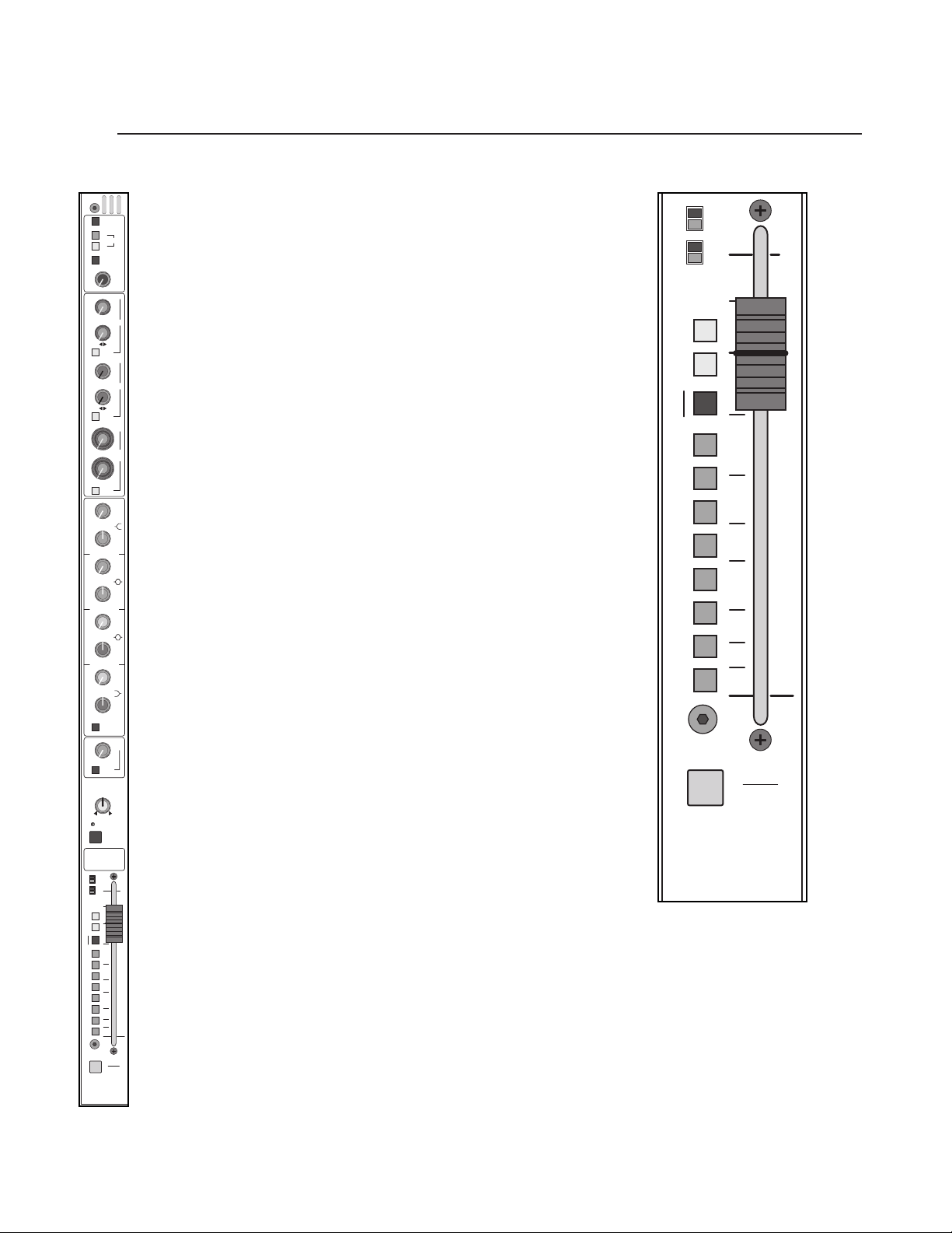
p. 38
stereo input module
2
X-VCA owner’s manual
GAIN
PRE
PRE
AUX
1
2
3
4
5
6
7
8
PK
SIG
L
R
ODD - LR - EVEN
BAL
STEREO INPUT
MUTE
SAFE
PREVIEW
=
HPF
20 400
40
80
200
EQ
ON
PRE
5
6
3
4
7
8
1
2
600
1K
2K
3K
8K
400
5K
LF
LM
HM
HF
150
500
1K
2K
100
60
400
800
40
M
L-R
BAL ON
GROUPS
40
12
6
0
6
•
3
20
+
–
40
12
6
0
6
•
3
20
+
–
40
20
10
0
6
•
3
30
+
–
40
20
10
0
6
•
3
30
+
–
40
20
10
0
6
•
3
30
+
–
40
20
10
0
6
•
3
30
+
–
3K
6K
12K
20K
1K
18K
1.5
15
6
0
6
25
10
3
+–
0
1515
88
+–
0
1515
88
+–
0
1515
88
+–
0
1515
88
+–
5
10
0
5
10
20
30
15
50
40
SOLO
VCA
ASSIGN
LINE 2
Ø
MONO
L
R
1
2
3
4
5
6
7
8
PK
SIG
L
R
M
L-R
BAL ON
GROUPS
5
10
0
5
10
20
30
15
50
40
SOLO
VCA
ASSIGN
Page 39

2
p. 39
stereo input module
features
input fader
The input fader is the primary level control for signals being sent to any of the
consoles mix buses.The signals affected are the AUX sends selected to be prefader.The fader offers greater than 80dB of attenuation and up to 10dB of boost .
Normal operation is between -10 and 0.The fader itself is a 100mm 10K linear
taper slide potentiometer. It controls the voltage to the channel's VCA. No audio
passes through the fader.
solo switch
Pressing this momentary switch will include (illuminate) or exclude (not-illu-
minated) the channel from the consoles solo system.
See SOLO FEATURES section.
Page 40
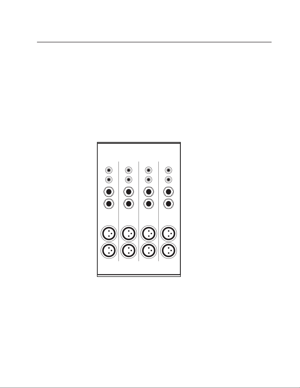
p. 40
X-VCA owner’s manual
stereo input module
2
Bal Line In 2 Bal Line In 2 Bal Line In 2 Bal Line In 2
L
R
L
R
L
R
L
R
Bal Line In 1 Bal Line In 1 Bal Line In 1 Bal Line In 1
L
R
L
R
L
R
L
R
Line In 2 Line In 2 Line In 2 Line In 2
L
R
L
R
L
R
L
R
Page 41

p. 41
stereo input module
2
rear panel features
The stereo line-input module provides connectors for three stereo line-level signals. see—line 2 switch.
balanced left and right line-in XLR connectors
These two jacks accept balanced or unbalanced +4dB line level sig-
nals.The
LINE 2 switch on front-panel must be disengaged for these connectors to
be active.
line-input left and right 1/4" TRS jacks
These two jacks accept balanced or unbalanced line level
signals.The LINE 2 switch on front panel must be engaged for these jacks to be
active.
line-input left and right RCA connectors
These two jacks accept unbalanced line-level signals.They are active when the LINE
2 switch on front-panel is engaged and nothing is plugged into the corresponding
left or right 1/4" TRS jack(s).
Page 42

p. 42
group module
3
X-VCA owner’s manual
module panel
SOLO
SAFE
PREVIEW
AUX 1–2
STEREO PAIR
INPUT SENDS
LEV
PAN
OUTPUT
LEV
SOLO
TALK
TO
MUTE
SAFE
PREVIEW
OUTPUT
LEV
AUX
2
TALK
TO
MUTE
AUX
1
40
15
10
0
10
•
5
20
+
–
40
15
10
0
10
•
5
20
+
–
1
2
block diagram
E
UNITY
LEV
LEV
1
2
3
4
THR
RATIO
1:11:5
GAIN
(DB)
:
)
(
1
N
THR
)
DBU
10
5
0
5
10
15
20
30
40
50
10
5
0
5
10
15
20
30
40
50
PAN
SAFE
PREVIEW
MUTE
10
15
20
40
•
MATRIX
SENDS
10
20
30
40
•
10
20
30
40
•
10
20
30
40
•
10
20
30
40
•
MTX SENDS
POST GRP 2
:
1
2
GATE
30
40
50
60
6
31612
2
020
4
2
C
O
M
P
1
25
35
401515
STEREO
LINK
=
LR
SAFE
PREVIEW
MUTE
THR
ON
GATE
1
2
3
5
GRP
7
ATT
9
(DB)
12
15
18
21
COMP
SOFT
KNEE
VOX
AUTO
PERC
THR
ON
GRP DYN
GROUP
ASSIGN
M
L-R
GROUP
INSERT
ON
PK
SIG
MUTE
VCA
2
UNITY
EDIT
VCA 2
ASSIGN
AUX
OUTPUT
–
0
10
TALK
TO
SOLO
–
0
6
–
0
6
–
0
6
–
0
6
25
–
20
20
–
0
GROUP
GRP
SOLO
VCA
ASSIGN
VCA 2
SOLO
ASSIGN
1
2
2
LEV
+
5
1
+
3
2
+
3
3
+
3
4
+
3
THR
RATIO
:
1
1
GAIN
(DB)
RATIO
:
(
1
N
10
THR
(
DBU
+
10
1–2
PAN
20
30
40
50
2
20
30
40
50
)
)
10
5
0
5
10
15
10
5
0
5
10
15
VCA MASTERS
(1 OF 8 SHOWN)
MUTE
STEREO PAIR
AUX ODD/EVEN
AUX
SOLO
SOLO
GROUP
ASSIGN
TO
INPUT
MICRO
CARDS
COMPRESSOR CONTROL
CONTROL
EXPANDER
PFL
VCA
SLAVE
EDIT
ASSIGN
THRESH
LATCHES
VCA ASSIGN
TO GROUP FADER
MICRO
INTER-
GROUP
THRESH
-45 +15
RATIO
1:1 20:1
GAIN
0 DB +20
RATIO
-60 -20
FACE
CARD
1:5 1:1
MUTE
GROUP
VCA
SOLO
TIMING CONTROL
RMS
DETECTOR
SAFE
PREVIEW
FROM
FADER
MASTER
1 OF 4
CIRCUITS
MICRO
MASTER
AUX
OPTION
XFORMER
PART OF GROUP MICRO INTERFACE CARD
TO SOLO
SWITCHING
AUX
MUTE
AUX
LEVEL
TO SOLO
SWITCHING
GROUP DYNAMICS SUB-CARD
AUX
AUX
MUTE
SAFE
PREVIEW
INSERT
MIX AMP
CARD
BAL OUT
AUX
SEND RTN
AUX
MIX
INSERT RTN
+10
GC
∑
AUX POST
AUX PRE
TALK TO AUX
TB
X-VCA MASTER MODULE
FEED
PREVIEW
MUTE
10
15
20
40
•
MATRIX
SENDS
10
20
30
40
•
10
20
30
40
•
10
20
30
40
•
10
20
30
40
•
1
GATE
30
40
50
60
1:5
31612
2
020
2
C
O
M
P
1
25
35
401515
=
LR
PREVIEW
MUTE
THR
ON
GATE
1
2
3
5
GRP
7
ATT
9
(DB)
12
15
18
21
COMP
SOFT
KNEE
VOX
AUTO
PERC
THR
ON
GRP DYN
GROUP
ASSIGN
M
L-R
GROUP
INSERT
ON
PK
SIG
MUTE
VCA
1
UNITY
EDIT
VCA 1
ASSIGN
AUX 1–2
STEREO PAIR
INPUT SENDS
SAFE
AUX
1
OUTPUT
–
0
+
5
10
TALK
TO
SOLO
–
0
+
3
6
–
0
+
3
6
–
0
+
3
6
–
0
+
3
6
MTX SENDS
POST GRP 1
:
2
25
–
20
6
RATIO
4
10
20
–
(
0
+
10
COMP•GATE
GROUP
PAN
SAFE
GRP
1
SOLO
VCA
ASSIGN
VCA 1
SOLO
ASSIGN
TO SOLO BUS & MICRO INTERFAC
FREQ
LEVEL
FREQ
LEVEL
FREQ
LEVEL
FREQ
LEVEL
FREQ
LEVEL
Q
Q
Q
TALK TO L / R
TB
3 - 0.7
3 - 0.7
3 - 0.7
FEED
Page 43

p. 43
group module
3
group module features
The Group modules are physically configured in pairs, four pairs making up
the eight Groups. Each of the eight Group modules offer identical functions
for the eight associated Aux Masters, Audio Groups, and VCA Groups.
Each group module includes the following sections:
*Aux output control
*Matrix send
*Groups dynamics control with gain reduction meter
*Audio group with 100mm fader and VCA control
*VCA master group with 100mm fader
aux output control
AUX STEREO PAIR switch Each odd / even pair of Aux masters has an
Aux Stereo Pair switch for globally configuring the associated auxes for Level
/ Level or Level / Pan operation
The associated odd / even pair of Auxes function as individual, discrete
mono aux sends.
The associated odd / even pair of Auxes function as a stereo pair. The
odd numbered Aux acts as a Level control for the stereo pair and the even
numbered Aux acts as a pan control
mute
Mute switch
See LOCAL MICROPROCESSOR CONTROL section
Aux master output level (1 - 8)
The AUX MASTER output level controls set the levels that appear at the
corresponding AUX output connectors on the rear-panel.
Talk to (1 - 8)
Adds the TALKBACK system output to the associated AUX output.The
level of the TALKBACK signal is set by the TALKBACK level control in the MASTER section.
solo switch
Pressing this momentary switch will include (illuminate) or exclude (not-illu-
minated) the channel from the consoles solo system.
See SOLO FEATURES section.
write-in label
This label may be written on with a grease-marker, or dry-erase pen and later
wiped clean. Masking tape may also be placed on this surface, if desired. If you
write on it with a "Sharpie", you may have trouble getting the writing off. If this is
the case, your best bet is to wipe the label off with isopropyl (rubbing) alcohol.
Page 44

p. 44
group module
3
X-VCA owner’s manual
module panel
MATRIX
SENDS
1
2
3
4
1
2
3
4
MATRIX
SENDS
MTX SENDS
POST GRP 1
MTX SENDS
POST GRP 2
40
20
10
0
6
•
3
30
+
–
40
20
10
0
6
•
3
30
+
–
40
20
10
0
6
•
3
30
+
–
40
20
10
0
6
•
3
30
+
–
40
20
10
0
6
•
3
30
+
–
40
20
10
0
6
•
3
30
+
–
40
20
10
0
6
•
3
30
+
–
40
20
10
0
6
•
3
30
+
–
GATE GATE
THR
1:2
THR
1:2
30
25
40
30
25
40
block diagram
A
RIBBON
GROUP
VCA ASSIGN
O
(1
OF
8
SHOWN)
VC
LEV
LEV
1
2
3
4
THR
RATIO
1:11:5
GAIN
(DB)
:
)
(
1
N
THR
)
DBU
10
5
0
5
10
15
20
30
40
50
PAN
SAFE
PREVIEW
MUTE
10
15
20
40
•
MATRIX
SENDS
10
20
30
40
•
10
20
30
40
•
10
20
30
40
•
10
20
30
40
•
MTX SENDS
POST GRP 2
:
1
2
GATE
30
40
50
60
6
31612
2
020
4
2
C
O
M
P
1
25
35
401515
STEREO
LINK
=
LR
SAFE
PREVIEW
MUTE
THR
ON
GATE
1
2
3
5
GRP
7
ATT
9
(DB)
12
15
18
21
COMP
SOFT
KNEE
VOX
AUTO
PERC
THR
ON
GRP DYN
GROUP
ASSIGN
M
L-R
GROUP
INSERT
ON
PK
SIG
1
2
AUX
2
OUTPUT
–
LEV
0
+
5
TALK
6
6
6
6
20
–
ASSIGN
TO
0
0
0
0
25
20
0
GROUP
GRP
SOLO
VCA
1
+
3
2
+
3
3
+
3
4
+
3
THR
RATIO
:
1
1
GAIN
(DB)
RATIO
(
N
10
THR
(
DBU
+
10
1–2
PAN
2
PA N
GROUP
:
)
1
)
GROUP
10
5
0
5
10
15
20
30
40
50
SWITCHES
BUS ASSIGN
CABLE
INTER-
CONNECT
10
SOLO
–
–
–
–
–
ON
INSERT
GROUP
GROUP INSERT
MIX AMP
GROUP PRE
SEND RTN
GC
∑
MIX
GRP
PK
MATRIX
M1
POST
SENDS
GROUP
M2
SIG
GROUP PRE
M3
GROUP
POST
GROUP
M4
METER
ATTENUATION
TO EXT MTX
12357
ON
COMP
ON
THRESH
9
121518
ON
THRESH
AUX PRE
& SWITCHING
SOLO CONTROL
AFL MODE
SOLO LEFT
AUTO
VOX PERC
SOFT
KNEE
21
ON
GATE
AUX POST
SOLO RIGHT
STEREO PAIR
AUX ODD/EVEN
AUX
SOLO
SOLO
GROUP
ASSIGN
TO
INPUT
MICRO
CARDS
COMPRESSOR CONTR
CONTROL
EXPANDER
PFL
VCA
SLAVE
TO GROUP FADER
SAFE
PREVIEW
MUTE
10
15
20
40
•
MATRIX
SENDS
10
20
30
40
•
10
20
30
40
•
10
20
30
40
•
10
20
30
40
•
MTX SENDS
POST GRP 1
:
1
2
GATE
30
40
50
60
1:5
6
31612
2
020
2
C
O
M
P
1
25
35
401515
COMP•GATE
=
LR
SAFE
PREVIEW
MUTE
THR
ON
GATE
1
2
3
5
GRP
7
ATT
9
(DB)
12
15
18
21
COMP
SOFT
KNEE
VOX
AUTO
PERC
THR
ON
GRP DYN
GROUP
ASSIGN
M
L-R
GROUP
INSERT
ON
PK
SIG
AUX 1–2
STEREO PAIR
INPUT SENDS
AUX
1
OUTPUT
–
0
+
5
10
TALK
TO
SOLO
–
0
+
3
6
–
0
+
3
6
–
0
+
3
6
–
0
+
3
6
25
–
20
RATIO
4
10
20
–
(
0
+
10
GROUP
PAN
GRP
1
SOLO
VCA
ASSIGN
MUTE
VCA
1
UNITY
EDIT
VCA 1
ASSIGN
VCA 1
SOLO
ASSIGN
10
5
UNITY
0
5
10
15
20
30
40
50
MUTE
VCA
VCA 2
ASSIGN
2
EDIT
10
5
0
5
10
15
20
30
40
50
VCA 2
SOLO
ASSIGN
SOLO LEFT
SOLO CONTROL
VCA
SOLO
ASSIGN
SOLO RIGHT
& SWITCHING
TO
NEXT
MODULE
SES 1-8
MASTER
CARD
MICRO
INTERFACE
INPUT CHAN
ASSIGN
VCA,
MUTE
MUTE
TCHES
AND
CTRL
SOLO
PREV
FROM
1 OF 4
SAFE
PREVIEW
SENDS
MODULE
CIRCUITS
RU 4
1-2 LEV/PAN CTRL
V
AUX 3
AUX 4
3-4 LEV/PAN CTRL
N
AUX 2
AUX 1
N
V
Page 45

matrix sends
The X-VCA includes four MATRIX
outputs. Each of these outputs can be made up
of signals from the eight
GROUPS; the left, right and mono buses;and an external
source. See Master section for more information. For expanded Matrixing capabilities, a 37 pin d-sub connector is included on the rare panel which contains all or
the primary outputs. See Group module rear panel description for more information.
matrix 1–4 levels—M1,M2,M3,M4
These level controls are used to mix the group's signal into the correspond-
ing matrix.
post-group
The
GROUP
fader setting has no effect on the group-to-matrix level controls
1–4.
The
GROUP
fader is introduced into the signal path and will control the signal
level.When the group is muted, the group's signals to matrix 1-4 are muted as
well.
p. 45
group module
3
Page 46

p. 46
group module
3
X-VCA owner’s manual
module panel
31612
2
020
6
THR
(
DBU
)
STEREO
LINK
GATE
C
O
M
P
RATIO
(
N:1
)
GAIN
(DB)
10
–
+
35
401515
0
25
1–2
GATE
1
4
20
10
2
RATIO
THR
1:5
1
:
2
31612
2
020
6
THR
(
DBU
)
C
O
M
P
RATIO
(
N:1
)
GAIN
(DB)
10
–
+
35
401515
0
25
COMP •GATE
RATIO
THR
1:11:5
1
:
2
1
:
1
1
4
20
10
2
50
60
30
–
20
25
40
50
60
30
–
20
25
40
block diagram
SIG
INSERT
AUX
MUTE
SWITCHING
SWITCHING
GROUP
PRE
S
B
LEVEL
PREVIEW
MUTE
10
15
20
40
•
MATRIX
SENDS
10
20
30
40
•
10
20
30
40
•
10
20
30
40
•
10
20
30
40
•
GATE
40
50
60
1:5
31612
2
020
2
C
O
M
P
1
25
35
401515
LR
PREVIEW
MUTE
THR
ON
GATE
1
2
3
5
GRP
7
ATT
9
(DB)
12
15
18
21
COMP
SOFT
KNEE
VOX
AUTO
PERC
THR
ON
GRP DYN
GROUP
ASSIGN
M
L-R
GROUP
INSERT
ON
PK
SIG
AUX 1–2
STEREO PAIR
INPUT SENDS
SAFE
AUX
OUTPUT
–
0
10
TALK
TO
SOLO
–
0
6
–
0
6
–
0
6
–
0
6
MTX SENDS
POST GRP 1
:
1
2
30
–
20
6
4
–
0
COMP•GATE
GROUP
=
SAFE
GRP
SOLO
VCA
ASSIGN
1
LEV
+
5
1
+
3
2
+
3
3
+
3
4
+
3
THR
25
RATIO
1:11:5
GAIN
(DB)
RATIO
:
(
1
N
10
20
THR
(
DBU
+
10
PAN
1
MUTE
20
MATRIX
SENDS
30
30
30
30
GATE
50
60
)
C
O
M
P
)
MUTE
10
5
1
0
2
3
5
7
9
12
5
15
18
21
10
SOFT
KNEE
15
VOX
AUTO
PERC
20
GRP DYN
30
40
M
50
L-R
ON
LEV
PAN
SAFE
PREVIEW
10
–
15
40
10
•
SOLO
10
–
20
40
•
10
–
20
40
•
10
–
20
40
•
10
–
20
40
•
MTX SENDS
POST GRP 2
:
1
2
30
40
–
6
31612
2
020
4
2
1
25
35
401515
STEREO
LINK
=
LR
SAFE
PREVIEW
THR
ON
GATE
GRP
ATT
(DB)
COMP
THR
ON
GROUP
ASSIGN
GROUP
INSERT
PK
SIG
1
2
AUX
2
OUTPUT
LEV
0
+
5
TALK
TO
1
0
+
3
6
2
0
+
3
6
3
0
+
3
6
4
0
+
3
6
THR
25
RATIO
20
:
1
1
GAIN
(DB)
RATIO
:
)
(
1
N
10
20
THR
–
(
)
DBU
0
+
10
1–2
GROUP
PAN
10
5
0
5
10
15
20
30
40
50
GRP
2
SOLO
VCA
ASSIGN
END
METER
BUSES 1-8
VCA MASTER
FADER
GROUP
GROUP
ATTENUATION
POST
GROUP
BUS IN
MICRO
CONTROL
LATCHES
VCA ASSIGN
12357
METER
CV
ON
COMP
ON
THRESH
9
121518
ON
THRESH
MIX BUS
TO GROUP
TO ADJACENT CHANNEL
LINK
AUTO
VOX PERC
SOFT
KNEE
21
ON
GATE
ODD/EVEN PAIRS
UNITY
VCA MASTERS
(1 OF 8 SHOWN)
MUTE
COMPRESSOR CONTROL
CONTROL
EXPANDER
PFL
VCA
SLAVE
EDIT
ASSIGN
CV
THRESH
-45 +15
RATIO
1:1 20:1
GAIN
0 DB +20
-60 -20
THRESH
TO RIB
RATIO
1:5 1:1
SOLO
TIMING CONTROL
RMS
VCA
MASTER
DETECTOR
FADER
XFORMER
PART OF GROUP MICRO INTERFACE CARD
TO SOLO
AUX
AUX
TO SOLO
GROUP DYNAMICS SUB-CARD
MUTE
VCA
1
UNITY
EDIT
VCA 1
ASSIGN
VCA 1
SOLO
ASSIGN
10
5
UNITY
0
5
10
15
20
30
40
50
MUTE
VCA
ASSIGN
10
2
0
10
15
20
EDIT
30
VCA 2
40
50
VCA 2
SOLO
ASSIGN
5
5
M3
M4
MTX
AUX POST
AUX PRE
& SWITCHING
SOLO CONTROL
STEREO PAIR
AUX ODD/EVEN
AUX
SOLO
SOLO
GROUP
ASSIGN
LATCHES
VCA ASSIGN
TO GROUP FADER
TER-
ICRO
ROUP
ACE
ARD
GROUP
MUTE
SAFE
PREVIEW
OF 4
CUITS
AUX
MUTE
SAFE
AUX
PREVIEW
Page 47

group dynamics section
The X-VCA Audio Group and Master modules include a number of features
for flexible dynamic control of signal levels. On Group modules, the compressor and gate functions may be engaged separately or simultaneously. For
a comprehensive discussion of these features, see Section on Dynamics
Control Operation.
gate
The gate is used to attenuate or silence the signal when it's level falls below
a selected point (threshold).
THRESHOLD (THR) control (center knob of dual concentric control)
Adjusts the point at which any DECREASE in input signal level will
cause a further reduction in output level (gain) as determined by the ratio
control setting. Threshold may be set between -20db and -60db (and
below).
RATIO control (outside of dual concentric control)
Adjusts the proportion of output signal in relation to input signal
when operating BELOW the set gate threshold level. Ratio may be adjusted
from 1:1 to above 1:5. Gating demonstrates "soft knee" characteristics.
compressor
The compressor is used to reduce a signals dynamic range by the selected
ratio. It can also be configured to limit the signals output level.
GAIN (make up) control
Adjusts to make up for apparent gain loss due to compression of input
signals. In the Solo Pre position (default), the output of the dynamics section can be viewed before the VCA control system fader. The gain control
should be adjusted to show near 0 reference level when normal signals are
present. The GAIN control has a range of 0db to +20db.
RATIO control
Adjusts the proportion of output signal in relation to input signal above
the set threshold level. The ratio of input to output signal may be adjusted
from 1:1 to greater than 20:1 (hard limiting).
THRESHOLD (THR) control
Adjusts point at which any increase in input signal to the
compressor/limiter section will cause a reduction in output level at a rate
determined by the ratio control setting. The threshold may be set between
-45db and +15db.
COMP-GATE stereo link
Links the odd and even GROUP's dynamics sections for stereo operation. The GROUP with the highest amount of auto-attenuation controls the
dynamics sections for both groups in the odd/even pair.
p. 47
group module
NOTE: This dynamics
section is intended for
use by an experienced operator. It's best to be familiar
with compressors and limiters before using them in
critical applications!
+
3
Page 48

p. 48
group module
3
X-VCA owner’s manual
3
module panel
MUTE
SAFE
PREVIEW
GRP
ATT
(DB)
VOX
PERC
AUTO
SOFT
KNEE
1
2
3
5
7
9
12
15
18
21
COMP
GATE
LR
=
ON
M
L-R
GROUP
ASSIGN
GROUP
INSERT
GRP DYN
PK
SIG
GRP
1
MUTE
SAFE
PREVIEW
LR
GROUP
PAN
=
GRP
2
GROUP
PAN
VOX
PERC
AUTO
SOFT
KNEE
1
2
3
5
7
9
12
15
18
21
COMP
GATE
GRP DYN
THR
ON
THR
ON
THR
ON
THR
ON
SOLO
VCA
ASSIGN
SOLO
VCA
ASSIGN
5
10
0
5
10
20
30
15
50
40
5
10
0
5
10
20
30
15
50
40
GRP
ATT
(DB)
ON
M
L-R
GROUP
ASSIGN
GROUP
INSERT
PK
SIG
block diagram
SIG
INSERT
AUX
MUTE
SWITCHING
SWITCHING
GROUP
PRE
S
B
LEVEL
PREVIEW
MUTE
10
15
20
40
•
MATRIX
SENDS
10
20
30
40
•
10
20
30
40
•
10
20
30
40
•
10
20
30
40
•
GATE
40
50
60
1:5
31612
2
020
2
C
O
M
P
1
25
35
401515
LR
PREVIEW
MUTE
THR
ON
GATE
1
2
3
5
GRP
7
ATT
9
(DB)
12
15
18
21
COMP
SOFT
KNEE
VOX
AUTO
PERC
THR
ON
GRP DYN
GROUP
ASSIGN
M
L-R
GROUP
INSERT
ON
PK
SIG
MUTE
VCA
1
UNITY
EDIT
VCA 1
ASSIGN
LEV
AUX 1–2
STEREO PAIR
PAN
INPUT SENDS
SAFE
SAFE
PREVIEW
AUX
1
MUTE
OUTPUT
10
–
–
LEV
15
0
+
5
20
40
10
10
•
TALK
TO
SOLO
SOLO
MATRIX
SENDS
10
–
–
1
0
20
+
3
30
40
6
•
10
–
–
2
0
20
+
3
30
40
6
•
10
–
–
3
0
20
+
3
30
40
6
•
10
–
–
4
0
20
+
3
30
40
6
•
MTX SENDS
MTX SENDS
POST GRP 1
POST GRP 2
THR
:
:
1
1
2
2
GATE
30
30
40
25
RATIO
50
60
–
–
20
1:11:5
6
6
GAIN
31612
(DB)
2
020
RATIO
4
4
(
)
N:1
2
C
10
O
M
20
P
1
THR
–
(
)
DBU
25
0
+
10
35
401515
STEREO
COMP•GATE
LINK
GROUP
=
=
PAN
LR
SAFE
SAFE
PREVIEW
MUTE
10
THR
ON
5
GATE
1
0
2
3
5
GRP
7
ATT
9
(DB)
12
5
15
18
21
COMP
10
SOFT
KNEE
15
VOX
AUTO
PERC
20
THR
ON
GRP DYN
30
GROUP
ASSIGN
40
M
50
L-R
GROUP
INSERT
ON
PK
GRP
1
SIG
SOLO
VCA
ASSIGN
MUTE
10
VCA
5
2
UNITY
0
5
10
15
20
EDIT
30
VCA 2
ASSIGN
40
50
VCA 1
SOLO
ASSIGN
1
2
AUX
2
OUTPUT
LEV
0
+
5
TALK
TO
1
0
+
3
6
2
0
+
3
6
3
0
+
3
6
4
0
+
3
6
THR
25
RATIO
20
:
1
1
GAIN
(DB)
RATIO
(
)
N:1
10
20
THR
–
(
)
DBU
0
+
10
1–2
GROUP
PAN
10
5
0
5
10
15
20
30
40
50
GRP
2
SOLO
VCA
ASSIGN
10
5
0
5
10
15
20
30
40
50
VCA 2
SOLO
ASSIGN
END
METER
BUSES 1-8
VCA MASTER
FADER
GROUP
GROUP
POST
GROUP
M3
M4
BUS IN
MICRO
CONTROL
LATCHES
VCA ASSIGN
12357
METER
ATTENUATION
MTX
MIX BUS
TO GROUP
LINK
CV
ON
AUTO
COMP
VOX PERC
ON
THRESH
SOFT
KNEE
9
121518
ON
GATE
ON
THRESH
AUX POST
AUX PRE
& SWITCHING
SOLO CONTROL
ODD/EVEN PAIRS
TO ADJACENT CHANNEL
21
AUX ODD/EVEN
AUX
GROUP
VCA MASTERS
(1 OF 8 SHOWN)
MUTE
COMPRESSOR CONTROL
CONTROL
EXPANDER
PFL
SLAVE
STEREO PAIR
SOLO
SOLO
ASSIGN
UNITY
VCA
EDIT
ASSIGN
THRESH
RATIO
GAIN
-60 -20
THRESH
LATCHES
VCA ASSIGN
TO GROUP FADER
TER-
ICRO
ROUP
CV
-45 +15
1:1 20:1
0 DB +20
RATIO
ARD
ACE
TO RIB
1:5 1:1
MUTE
GROUP
SOLO
TIMING CONTROL
RMS
DETECTOR
SAFE
PREVIEW
VCA
FADER
MASTER
CUITS
OF 4
XFORMER
PART OF GROUP MICRO INTERFACE CARD
TO SOLO
AUX
AUX
TO SOLO
GROUP DYNAMICS SUB-CARD
AUX
AUX
MUTE
SAFE
PREVIEW
Page 49
group dynamics section
Note:The following dynamics controls are located adjacent to the Group fader.
gate ON (downward expander)
Activates the gate (downward expander) function.
gate ON/THR (Threshold) dual color LED
Illuminates GREEN when the gate system is active. Illuminates RED when
the group's signal level reaches the threshold level set by the GATE THR control.
Note that red threshold indication is functioning at all times, even when gate is
not active (switched off).
gain reduction meter (ATT)
This ten-segment meter indicates the overall gain reduction applied to input signals by the dynamics system by
either the gate function or the compressor function. If both gate and compressor
functions are switched on, one of the two bi-color LEDs (gate ON/THR or comp
ON/THR) will illuminate red to show which function is at threshold and causing
the gain reduction.
comp SOFT KNEE Switch - Changes initial compression characteristic
between Hard and Soft Knee.
Hard Compression - Immediately reduces compressor output signal levels at
the set compression ratio as soon as compressor input signal reaches the set
threshold.
Soft Compression - At threshold, reduces output signal level at a variable
compression ratio over an increasing input signal level until the set compression
ratio is achieved.
comp VOX on Switch
Activates the compressor/limiter system. Attack and release times are optimized for vocal applications.
comp PERC on Switch
Activates the compressor/limiter system.Attack and release times are optimized for percussion applications.
comp AUTO on (both V OX and PERC switches depressed)
When both the VOX and PERC switches are depressed, the compressor/limiter system is activated with automatic control of attack and release times
as determined by signal characteristics.
comp ON/THR (Threshold) dual color LED
Illuminates GREEN when the compressor system is activated by either the
VOX or PERC switch, or both. Illuminates RED when the channel’s signal level
reaches the threshold set on the COMP THR (threshold) control.
p. 49
group module
3
LED
LEDLEDLEDLEDLEDLEDLEDLEDLEDLED
LED
Page 50

p. 50
group module
3
X-VCA owner’s manual
3
module
panel
MUTE
SAFE
PREVIEW
GRP
ATT
(DB)
VOX
PERC
AUTO
SOFT
KNEE
1
2
3
5
7
9
12
15
18
21
COMP
GATE
LR
=
ON
M
L-R
GROUP
ASSIGN
GROUP
INSERT
GRP DYN
PK
SIG
GRP
1
MUTE
SAFE
PREVIEW
LR
GROUP
PAN
=
GRP
2
GROUP
PAN
VOX
PERC
AUTO
SOFT
KNEE
1
2
3
5
7
9
12
15
18
21
COMP
GATE
GRP DYN
THR
ON
THR
ON
THR
ON
THR
ON
SOLO
VCA
ASSIGN
SOLO
VCA
ASSIGN
5
10
0
5
10
20
30
15
50
40
5
10
0
5
10
20
30
15
50
40
GRP
ATT
(DB)
ON
M
L-R
GROUP
ASSIGN
GROUP
INSERT
PK
SIG
block diagram
T
TO GROUP FADER
R
MUTE
15
20
40
•
MATRIX
SENDS
20
30
40
•
20
30
40
•
20
30
40
•
20
30
40
•
GATE
40
50
60
1:5
31612
2
020
2
C
O
M
P
1
25
35
401515
LR
MUTE
THR
ON
GATE
1
2
3
5
GRP
7
ATT
9
(DB)
12
15
18
21
COMP
SOFT
KNEE
VOX
AUTO
PERC
THR
ON
GRP DYN
GROUP
ASSIGN
M
L-R
GROUP
INSERT
ON
PK
SIG
MUTE
VCA
1
UNITY
EDIT
VCA 1
ASSIGN
LEV
AUX 1–2
STEREO PAIR
PAN
INPUT SENDS
SAFE
PREVIEW
10
10
10
10
10
PREVIEW
SAFE
PREVIEW
AUX
AUX
1
MUTE
OUTPUT
OUTPUT
10
–
–
LEV
15
0
0
+
5
20
40
10
10
•
TALK
TALK
SOLO
–
0
6
–
0
6
–
0
6
–
0
6
MTX SENDS
POST GRP 1
:
1
2
30
–
20
6
4
–
COMP•GATE
GROUP
=
SAFE
SOLO
ASSIGN
VCA 1
SOLO
ASSIGN
TO
TO
SOLO
MATRIX
SENDS
10
–
1
0
20
+
3
30
40
6
•
10
–
2
0
20
+
3
30
40
6
•
10
–
3
0
20
+
3
30
40
6
•
10
–
4
0
20
+
3
30
40
6
•
MTX SENDS
POST GRP 2
THR
:
1
2
GATE
30
40
25
25
RATIO
50
60
–
20
1:11:5
6
GAIN
31612
(DB)
2
020
RATIO
4
:
)
(
1
N
2
C
10
O
M
20
20
P
1
THR
–
(
)
DBU
25
0
0
+
10
35
401515
STEREO
LINK
GROUP
=
PAN
LR
SAFE
PREVIEW
MUTE
10
THR
ON
5
GATE
1
0
2
3
5
GRP
7
ATT
9
(DB)
12
5
15
18
21
COMP
10
SOFT
KNEE
15
VOX
AUTO
PERC
20
THR
ON
GRP DYN
30
GROUP
ASSIGN
40
M
50
L-R
GROUP
INSERT
ON
PK
GRP
GRP
1
SIG
SOLO
VCA
VCA
ASSIGN
MUTE
10
VCA
5
2
UNITY
0
5
10
15
20
EDIT
30
VCA 2
ASSIGN
40
50
VCA 2
SOLO
ASSIGN
1
2
2
LEV
+
5
1
+
3
2
+
3
3
+
3
4
+
3
THR
RATIO
:
1
1
GAIN
(DB)
RATIO
:
)
(
1
N
10
THR
(
)
DBU
+
10
1–2
PAN
10
5
0
5
10
15
20
30
40
50
2
10
5
0
5
10
15
20
30
40
50
XFORMER
(1 OF 8 SHOWN)
X-VCA GROUP OUTPUT
GROUP
PAN
GROUP
L-R
GROUP
SWITCHES
BUS ASSIGN
MONO
ECT
ON
LE
ER-
GRP
BAL OU
OPTION
GROUP
GROUP PRE
ON
INSERT
SEND RTN
GROUP INSERT
MIX AMP
MIX
GRP
POST
+10
VCA
GC
∑
BUS IN
VCA MASTERS
(1 OF 8 SHOWN)
MUTE
EXPANDER
PFL
STEREO PAIR
AUX ODD/EVEN
AUX
SOLO
SOLO
ASSIGN
TO
INPUT
MICRO
CARDS
COMPRESSOR CONTROL
CONTROL
SLAVE
UNITY
FACE CARD
VCA
GROUP
METER SEND
MICRO
CONTROL
GROUP
GROUP
FADER
GROUP
POST
ATTENUATION
LATCHES
VCA ASSIGN
12357
METER
BUSES 1-8
VCA MASTER
GRP
MUTE
PK
SIG
TO GROUP
CV
ON
COMP
ON
THRESH
9
121518
ON
THRESH
MIX BUS
ODD/EVEN PAIRS
TO ADJACENT CHANNEL
LINK
AUTO
VOX PERC
SOFT
KNEE
21
ON
GATE
AUX POST
AUX PRE
MATRIX
POST
SENDS
GROUP PRE
GROUP
GROUP
M1
M2
M3
M4
& SWITCHING
SOLO CONTROL
TO EXT MTX
AFL MODE
SOLO LEFT
SOLO RIGHT
Page 51
p. 51
group module
3
audio group control features
This section provides standard features for the Group bus masters. Signals that are
assigned to the Audio groups are summed together to make up the audio Groups. A
full featured dynamics control section (see previous section) can be engaged for processing the summed group signals.These signals can be assigned to the Left, Right and
Mono buses and appear at the Group output jacks on the rear panel.
group pan
The
PAN
pot is used to position the group signal within the stereo left / right
field.The signal must be assigned to left and right in order for the PA N control to
have any effect.
safe preview
Safe Preview LED
See LOCAL MICROPROCESSOR CONTROL section
mute
Mute switch
See LOCAL MICROPROCESSOR CONTROL section
audio group fader
This 100mm fader controls signal levels to the associated audio group outputs as
well as signals assigned to the left/right and mono (center) mix buses.
mono assignment switch
Post fader assignment of signal to the mono mix bus.
L-R stereo assignment switch
Post fader/post pan pot assignment of signal to the left and right stereo mix
buses.
Group insert ON switch
The Insert point is located after the group summing amp and before the
dynamics control system. External signal processors can be inserted into the
group via 1/4" TRS connectors (send and return) on the rear panel.The
SEND signal is unbalanced and the RETURN can accept both unbalanced
and balanced signals.
Insert is switched OUT. Any signal coming into the Insert RETURN
jack is ignored.The Insert SEND jack can be used to derive a pre dynamics,
pre fader output from the group without interrupting the group's normal
signal flow.
Insert is switched IN.The Insert RETURN jack is active.A signal
processor patched to the groups insert is switched into the signal path.
signal/peak LED
This dual color LED responds audio Group's signal level. It illuminates green
with varying brightness in proportion to the pre-fader audio signal.When the signal approaches clipping, either pre or post fader, the LED illuminates red.
solo switch
Pressing this momentary switch will include (illuminate) or exclude (not-illuminated) the channel from the consoles solo system.
See SOLO FEATURES section.
LED
LED
Page 52
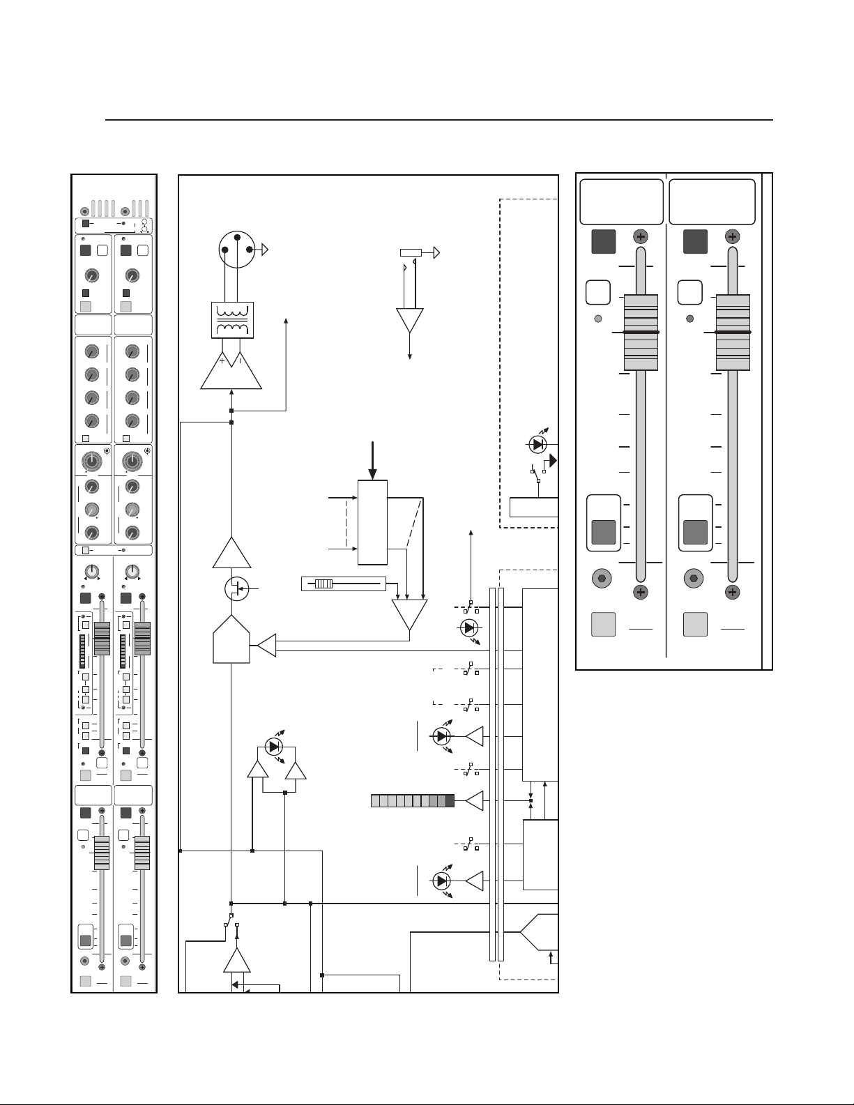
p. 52
group module
3
X-VCA owner’s manual
3
module
panel
MUTE
VCA
1
MUTE
VCA
2
5
10
0
5
10
20
30
15
50
40
UNITY
VCA 1
SOLO
ASSIGN
EDIT
VCA 1
ASSIGN
5
10
0
5
10
20
30
15
50
40
UNITY
VCA 2
SOLO
ASSIGN
EDIT
VCA 2
ASSIGN
block diagram
VCA
A
AUX 1–2
STEREO PAIR
INPUT SENDS
SAFE
PREVIEW
AUX
1
MUTE
OUTPUT
10
–
LEV
15
0
+
5
20
40
10
•
TALK
TO
SOLO
MATRIX
SENDS
10
–
1
0
20
+
3
30
40
6
•
10
–
2
0
20
+
3
30
40
6
•
10
–
3
0
20
+
3
30
40
6
•
10
–
4
0
20
+
3
30
40
6
•
MTX SENDS
POST GRP 1
THR
:
1
2
GATE
30
40
25
RATIO
50
60
–
20
1:5
1:11:5
6
GAIN
31612
(DB)
2
020
RATIO
4
(
)
N:1
2
C
10
O
M
20
P
1
THR
–
(
DBU
25
0
+
10
35
401515
COMP•GATE
GROUP
=
PAN
LR
SAFE
PREVIEW
MUTE
10
THR
ON
GATE
1
2
3
5
GRP
7
ATT
9
(DB)
12
15
18
21
COMP
10
SOFT
KNEE
15
VOX
AUTO
PERC
20
THR
ON
GRP DYN
30
GROUP
ASSIGN
40
M
50
L-R
GROUP
INSERT
ON
PK
GRP
1
SIG
SOLO
VCA
ASSIGN
MUTE
15
20
40
MATRIX
SENDS
20
30
40
20
30
40
20
30
40
20
30
40
GATE
40
50
60
31612
2
2
C
O
M
P
)
25
35
LR
MUTE
5
GATE
1
0
2
3
5
7
9
12
5
15
18
21
COMP
SOFT
KNEE
VOX
AUTO
PERC
GRP DYN
GROUP
ASSIGN
M
L-R
GROUP
INSERT
ON
PK
SIG
LEV
PAN
SAFE
PREVIEW
10
•
10
•
10
•
10
•
10
•
MTX SENDS
POST GRP 2
:
1
2
30
6
020
1
401515
STEREO
LINK
=
SAFE
PREVIEW
THR
ON
GRP
ATT
(DB)
THR
ON
1
2
AUX
2
OUTPUT
–
LEV
0
+
5
10
TALK
TO
SOLO
–
1
0
+
3
6
–
2
0
+
3
6
–
3
0
+
3
6
–
4
0
+
3
6
THR
25
RATIO
–
20
:
1
1
GAIN
(DB)
RATIO
4
(
)
N:1
10
20
THR
–
(
)
DBU
0
+
10
1–2
GROUP
PAN
GRP
BAL OUT
OPTION
XFORMER
POST
GROUP
+10
GROUP
METER SEND
BUSES 1-8
VCA MASTER
BUS IN
MICRO
CONTROL
LATCHES
VCA ASSIGN
MIX BUS
TO GROUP
ODD/EVEN PAIRS
VCA MASTERS
(1 OF 8 SHOWN)
MUTE
UNITY
CE CARD
TO ADJACENT CHANNEL
GRP
VCA
PK
MUTE
SIG
FADER
GROUP
CV
ON
COMP
LINK
AUTO
VOX PERC
ON
THRESH
SOFT
KNEE
COMPRESSOR CONTROL
ASSIGN
10
5
0
5
10
15
20
30
40
50
GRP
2
SOLO
VCA
GROUP PRE
MUTE
VCA
1
UNITY
EDIT
VCA 1
ASSIGN
VCA 1
SOLO
ASSIGN
MUTE
10
VCA
5
UNITY
0
5
10
15
20
30
ASSIGN
40
50
10
5
2
EDIT
VCA 2
VCA 2
SOLO
ASSIGN
0
5
10
15
20
30
40
50
INSERT
GROUP
ON
GROUP
GROUP
POST
METER
ATTENUATION
12357
9
121518
ON
THRESH
POST
21
ON
GATE
CONTROL
EXPANDER
PFL
SLAVE
Page 53
VCA group master control features
This section controls VCA levels of any assigned input channels or audio
groups assigned to the VCA group.VCA control of audio groups is a unique
feature not offered on most other VCA consoles. For more information on
using VCA control of audio groups, see Section on VCA Group Operation.
vca group Channel MUTE switch
This mute switch follows the assignment of the channels VCA system.
When activated, it mutes all assigned input and audio group channels except
when channel or group safe mode is activated. All primary and auxiliary
outputs will be muted, including pre fader aux sends if internal mute jumper
is in default pre fader mute YES position.
100mm VCA control fader
Controls relative volume levels of all input and audio group channels
assigned to the VCA group. (No audio passes through this fader.)
unity LED indicator
Illuminates when the fader is at its unity gain position. At unity gain,
input or audio group channels may be assigned (or removed from assignment) without a level change.
VCA Group edit switch
When selected, this switch allows editing of VCA assignments for input
and analog group channels. In this mode, the selected VCA Group Edit
switch will illuminate and flash. Only one Edit switch can be selected at a
time, and selection of the VCA Group Edit Switch will override any SOLO
switch selected (solo clear). To exit VCA Edit Mode, press the selected (illuminated and flashing) switch to toggle it to the off position.
Whenever a VCA Group Edit switch is flashing, the SOLO-VCA EDIT
switches will flash on all input and group channels assigned to that VCA
group.
For a complete discussion of VCA group editing, see section on VCA Group
Operation.
VCA SOLO switch
When selected, this switch illuminates and activates all input and audio
group SOLO switches assigned to that VCA group.All channels are monitored within the solo system as a related group. The VCA SOLO system
also may be used to quickly review VCA assignments, though no modification of assignment is permitted.
p. 53
group module
Caution: When assigning (or un-assigning)
active channels during a live
performance, care should be
exercised as a level change
will occur at any fader position other than UNITY.
+
3
LED
Page 54
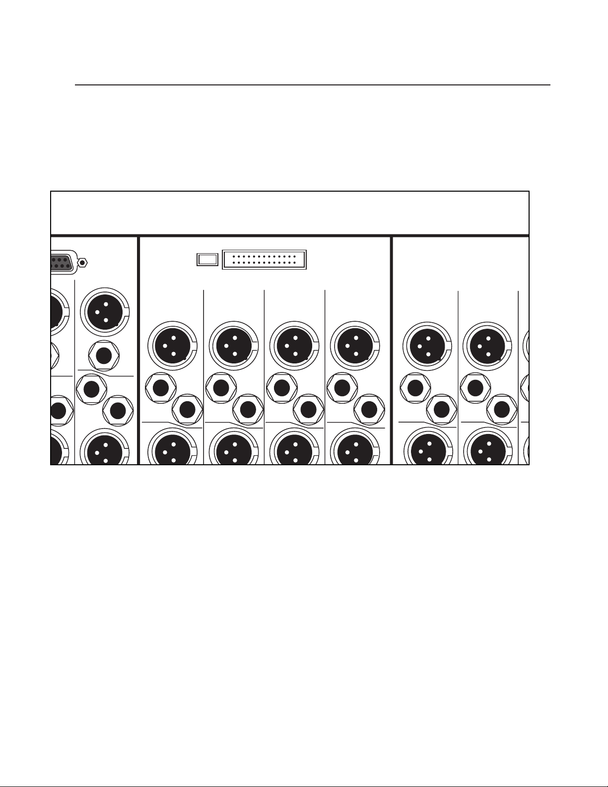
p. 54
group module
3
X-VCA owner’s manual
U
e
Matrix
Expansion
2 Matrix 1
Out
Group Out
In
Lamp
Dim
8
Group Out
7
Meter Bridge
6
Group Out
5
Group Out
4
Group Out
3
Group Out
nsert
end
Return
Left
Out
Insert
Send
Return
AUX
8
Insert
Send
Return
AUX
7
Insert
Send
Return
AUX
6
Insert
Send
Return
AUX
5
Insert
Send
Return
AUX
4
Insert
Send
Return R
AUX
3
Insert
Send
A
2
Page 55

p. 55
group module
3
rear panel features
lamp dim
Goose-neck lamps light-up at full intensity.
Goose-neck lamps light-up at medium intensity.
meter bridge connector
This connector carries all of the required connections up to the meter bridge.
While patching the console, care should be taken not to damage this connector
or the ribbon that plugs into it.
Page 56
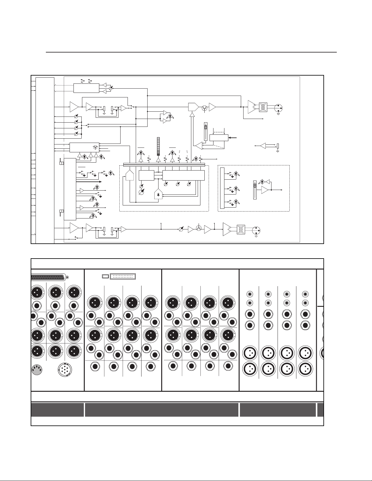
p. 56
group module
3
X-VCA owner’s manual
E
U
D
a
a
t
o
n
t
T
ULE
LE
M
V
RIBBON
CABLE
INTER-
CONNECT
GRP
MIX
TO EXT MTX
AFL MODE
SOLO LEFT
SOLO RIGHT
TO
INPUT
MICRO
CARDS
FROM
MASTER
MICRO
CARD
AUX
MIX
TB
FEED
GROUP
MICRO
INTER-
FACE
CARD
1 OF 4
CIRCUITS
TALK TO AUX
M1
M2
M3
M4
MONO
BUS ASSIGN
SWITCHES
MIX AMP
∑
SOLO CONTROL
& SWITCHING
GROUP
SOLO
ASSIGN
PREVIEW
PREVIEW
MIX AMP
∑
GROUP
GC
MATRIX
SENDS
POST
GROUP
SAFE
SAFE
GC
SOLO
L-R
AUX
GROUP INSERT
SEND RTN
GROUP PRE
AUX PRE
AUX ODD/EVEN
STEREO PAIR
TO GROUP FADER
VCA ASSIGN
LATCHES
GROUP
MUTE
AUX
MUTE
AUX
INSERT
SEND RTN
GROUP
PAN
AUX POST
GROUP
POST
GROUP
INSERT
ON
PFL
SLAVE
VCA
AUX
INSERT RTN
X-VCA GROUP OUTPUT
(1 OF 8 SHOWN)
GROUP
ATTENUATION
METER
1
2
3
5
7
THRESH
9
ON
12
15
GATE
18
ON
21
EXPANDER
CONTROL
THRESH
-60 -20
RATIO
1:5 1:1
RMS
DETECTOR
GROUP DYNAMICS SUB-CARD
TO SOLO
SWITCHING
AUX PRE
GROUP PRE
PK
SIG
THRESH
ON
SOFT
KNEE
COMPRESSOR CONTROL
GAIN
RATIO
0 DB +20
1:1 20:1
TIMING CONTROL
COMP
ON
AUTO
VOX PERC
THRESH
-45 +15
AUX
LEVEL
VCA
GROUP
FADER
CV
AUX
MUTE
LINK
+10
GRP
MUTE
VCA MASTER
BUSES 1-8
VCA ASSIGN
LATCHES
TO ADJACENT CHANNEL
ODD/EVEN PAIRS
TO SOLO
SWITCHING
+10
AUX POST
GROUP
POST
PART OF GROUP MICRO INTERFACE CARD
MUTE
EDIT
ASSIGN
SOLO
MICRO
CONTROL
XFORMER
OPTION
XFORMER
OPTION
GROUP
METER SEND
TO GROUP
MIX BUS
VCA MASTERS
(1 OF 8 SHOWN)
UNITY
VCA
MASTER
FADER
AUX
BAL OUT
BUS IN
GRP
BAL OUT
CV
TO RIBBON
Matrix
Matrix 3 Matrix 2 Matrix 1
Out Out
In In
Expansion
8
Group Out
Lamp
Meter Bridge
Dim
7
Group Out6Group Out
5
Group Out
4
Group Out
3
Group Out2Group Out
1
Group Out
Line In 2 Line In 2 Line In 2 Line In 2
L
R
L
L
R
R
L
R
Bal Line In 2 Bal Line In 2 Bal Line In 2 Bal Line In 2
Insert
Send
urn
no
t
Assist Out Alt R Out Alt L Out
I
Out
Return
Right
Out
Insert
Send
Return
Left
Out
Insert
Send
DC In
Return
AUX
8
Return
Group In
8
Insert
Send
Insert
Send
Insert
Send
Return
AUX
7
Out
Return
Return
AUX
6
Out
Insert
Send
Return
Group In7Group In6Group In
Insert
Send
Return
AUX
5
Out Out
Insert
Send
Return
Insert
Send
Insert
Send
5
Insert
Send
Return
AUX
4
Insert
Send
Return
Group In4Group In3Group In2Group In
Insert
Send
Return
AUX
3
Out
Insert
Send
Return
Insert
Send
Return
AUX
2
Out
Return
Out Out
Insert
Send
Return
AUX
1
Return
Insert
L
Send
R
Bal Line In 1 Bal Line In 1 Bal Line In 1 Bal Line In 1
Insert
L
Send
R
L
R
L
R
1
L
R
L
R
I
n
s
e
r
t
B
L
L
R
R
B
master groups stereo inputs
Page 57
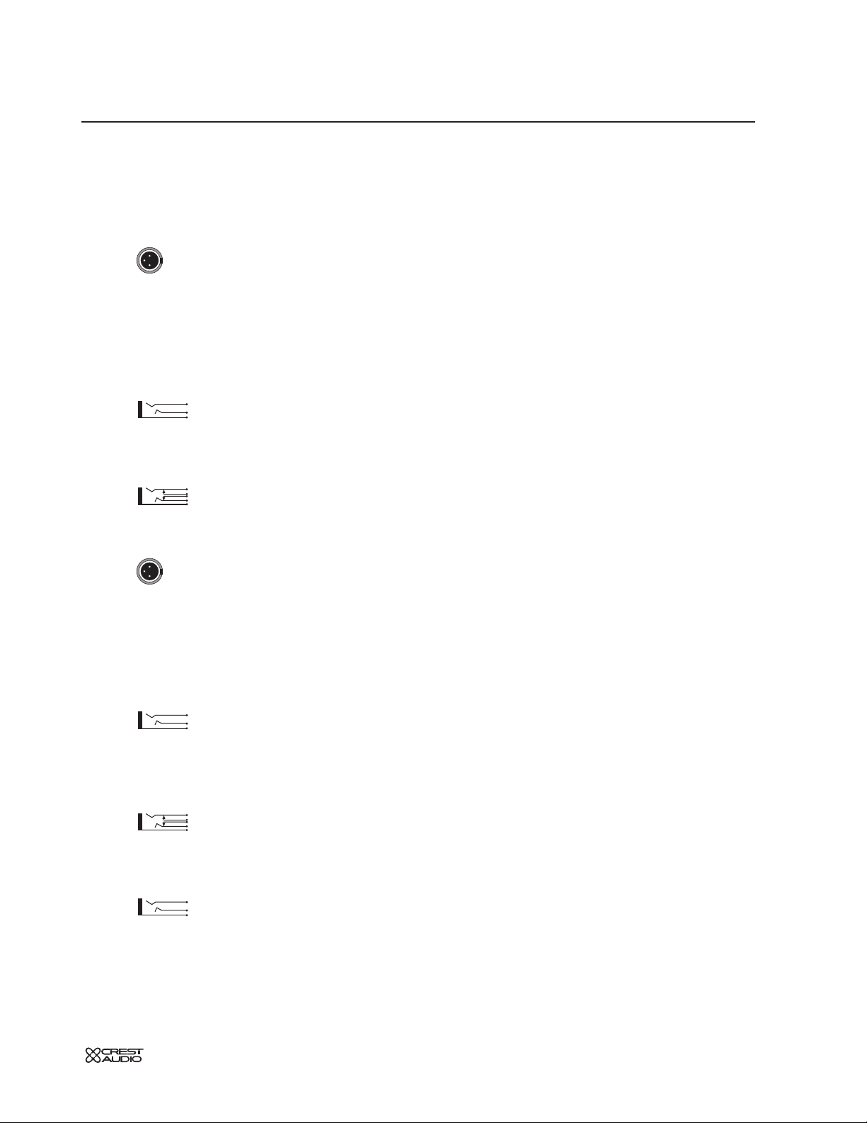
p. 57
group module
3
rear panel features
group output
This balanced male XLR connector carries the
GROUP output signal. see—
group fader, front-panel description
group insert point
Separate 1/4" TRS jacks provide the ability to insert an external signal processor
into the signal path of the GROUP. Insert is made active by depressing Group Insert
ON switch.
group insert send
This output connects to the input of an external signal processor. The
signal is derived after the group-summing amplifier. This output is ground compensated.
group insert return
This balanced input accepts a signal from the output of an external signal processor. It accepts either balanced or unbalanced signals.
aux output
This balanced male XLR connector carries the AUX output signal. see—aux
master, front-panel description
aux insert point
Separate 1/4" TRS jacks provide the ability to insert an external signal processor
into the signal path of the AUX. Insert is made active when a 1/4" TRS connector
is plugged into the Aux Insert return jack.
aux insert send
This output connects to the input of an external signal processor. The
signal is derived after the aux-summing amplifier. This output is ground compensated. It can also be used as pre-aux master level output without interrupting the
normal signal flow through the aux master section.
aux insert return
This balanced input accepts a signal from the output of an external signal processor. It accepts either balanced or unbalanced signals. Inserting a 1/4"
TRS plug into this jack makes the aux insert active.
group in
External signal can be introduced to the group by plugging a 1/4" TRS
connector into this jack. One primary purpose for the Group in jacks is to link
consoles together. The group outputs from another console can be fed into these
jacks, linking the group buses of the two consoles.
Page 58

p. 58
4
X-VCA owner’s manual
left / right & mono masters
module
panel
40
15
10
0
10
•
5
20
+
–
SOLO
SAFE
PREVIEW
OUTPUT
LEV
40
15
10
0
10
•
5
20
+
–
SOLO
TALK
TO
MUTE
SAFE
PREVIEW
OUTPUT
LEV
MTX
2
TALK
TO
MUTE
MTX
1
block diagram
N
S
L
M
S
A
M
A
N
U
A
L
M
U
T
E
S
C
E
N
E
S
SAFE
MTX
OUTPUT
–
0
+
5
10
TALK
TO
SOLO
–
0
+
3
6
–
0
+
3
6
–
0
+
3
6
–
0
+
3
6
MTX SENDS
POST LFT
12K
20K
.73
4K
8K400
.73
2K
4K200
.73
600
1.2K60
400
80040
EQ
ON
40 HZ
–
24DB/OCT
+
6
15
2006
ATT
SUM
L/R
TALK TO
L/R
1
LEV
18K
Q
6K
Q
3K
Q
1K
600
– +
FREQ
MAX
(
DBU
ON
1
3
6
9
12
18
24
(
DB
MATRIX
SENDS
1
2
3
4
1.5
HM
MID
LM
120
LF
100
)
)
RL
SAFE
PREVIEW
MUTE
10
–
15
20
40
10
•
TALK
SOLO
10
–
20
30
40
6
•
10
–
20
30
40
6
•
10
–
20
30
40
6
•
10
–
20
30
40
6
•
MTX SENDS
POST RT
6K
3K
1K
1.5
.73
2K
1K
1.5
.73
1K
500
1.5
.73
300
200
EQ
ON
MONO
40 HZ
–
24DB/OCT
OUTPUT LIMITER
–
+
3
2006
RATIO=20:1
LIMIT
ON
(
)
RMS
ATT
L/R TO
MONO
TALK TO
MONO
CENTER
PREVIEW
MUTE
10
15
20
40
•
MATRIX
SENDS
10
20
30
40
•
10
20
30
40
•
10
20
30
40
•
10
20
30
40
•
HF HF
6K
3K
1.5
1K
1.5
HM
2K
1K
1.5
MID
1K
500
1.5
LM
300
120
200
LF
100
L/R
OUTPUT LIMITER
–
3
RATIO=20:1
LIMIT
ON
(
)
RMS
L/R MONO
MTX
2
OUTPUT
LEV
0
+
5
TO
1
0
+
3
2
0
+
3
3
0
+
3
4
0
+
3
12K
18K
20K
Q
4K
6K
8K400
Q
2K
3K
4K200
Q
600
1K
1.2K60
400
600
80040
– +
FREQ
MAX
(
)
6
DBU
15
ON
1
3
6
9
12
18
24
(
)
DB
MONO
R
SOLO
EXT STR PGM
SHELVING EQ
STEREO 2-BAND
TO SOLO BUS
MONO
EXT STR PGM
ASSIGN
MATRIX CIRCUITRY 1 OF 4 SHOWN
MATRIX
BAL OUT
POST
MATRIX
MUTE
MATRIX
LEVEL
MATRIX
PRE
MATRIX
MIX AMP
PO
MO
SAFE
+10
(MICRO CONTROLLED)
MUTE AND SOLO SWITCHING
TO SOLO BUS & MICRO INTERFACE
SOLO MUTE
MATRIX
TALK TO
∑
PRVW
10
5
0
5
10
15
20
30
50
SOLO
L/R
PK
L
R
M
SIG
VCA
ASSIGN
SINGLE
FOLLOW
SCENE
EDIT
CHAN
VCA ASN
SELECT A
–
CHANNEL
TO ASSIGN
10
5
0
5
10
15
20
30
50
–
MONO
SOLO
TER
RO
ER-
E
UP
T &
ROL
RD
TO
MATRIX
SIDE
RIGHT
MIX
INPUT
MICRO
TB
CARDS
FEED
Page 59

4
p. 59
left / right & mono master modules
features
Aside from their Left / Right and Mono assignments, the X-VCA Left / Right and
Mono master modules contain identical features. One module is devoted to the
Left and Right stereo mix and the other module is devoted to the Mono mix.
Both modules contain the following sections:
* Matrix Output Control
* Matrix Send 1 though 4
* Output EQ
* RMS Output Limiter
* 100mm Faders
* Microprocessor Mute Controller
* Solo
Matrix output control
The Left / Right master module contains Matrix Master 1 and the Mono master
module contains Matrix Master 2.
mute
Mute switch
See LOCAL MICROPROCESSOR CONTROL section
Matrix master output level
The MATRIX MASTER output level controls set the levels that appear at
the corresponding MATRIX output connectors on the rear-panel.
Talk to
Adds the TALKBACK system output to the associated MATRIX output.The
level of the TALKBACK signal is set by the TALKBACK level control in the MASTER section.
solo switch
Pressing this momentary switch will include (illuminate) or exclude (not-illu-
minated) the channel from the consoles solo system.
See SOLO FEATURES section.
write-in label
This label may be written on with a grease-marker, or dry-erase pen and later
wiped clean. Masking tape may also be placed on this surface, if desired. If you
write on it with a "Sharpie", you may have trouble getting the writing off. If this is
the case, your best bet is to wipe the label off with isopropyl (rubbing) alcohol.
Page 60

p. 60
4
X-VCA owner’s manual
left / right & mono masters
module
panel
40
20
10
0
6
•
3
30
+
–
40
20
10
0
6
•
3
30
+
–
MATRIX
SENDS
40
20
10
0
6
•
3
30
+
–
40
20
10
0
6
•
3
30
+
–
MATRIX
SENDS
40
20
10
0
6
•
3
30
+
–
40
20
10
0
6
•
3
30
+
–
MTX SENDS
POST LFT
2
3
40
20
10
0
6
•
3
30
+
–
40
20
10
0
6
•
3
30
+
–
MTX SENDS
POST RT
2
3
1
4
1
4
block diagram
Q
F
S
M
S
A
M
A
N
U
A
L
M
U
T
E
S
C
E
N
E
S
SAFE
PREVIEW
MUTE
10
15
20
40
•
MATRIX
SENDS
10
20
30
40
•
10
20
30
40
•
10
20
30
40
•
10
20
30
40
•
MTX SENDS
POST LFT
HF HF
6K
3K
1.5
1K
1.5
HM
2K
1K
1.5
MID
1K
500
1.5
LM
300
120
200
LF
100
EQ
ON
L/R
–
OUTPUT LIMITER
–
3
RATIO=20:1
LIMIT
ON
(
)
RMS
L/R MONO
TALK TO
OUTPUT
–
0
10
TALK
SOLO
–
0
6
–
0
6
–
0
6
–
0
6
20K
.73
8K400
.73
4K200
.73
600
1.2K60
80040
40 HZ
24DB/OCT
+
6
2006
ATT
SUM
L/R
L/R
10
5
0
5
10
15
20
30
50
L/R
SOLO
MTX
1
+
5
TO
+
3
+
3
+
3
+
3
12K
18K
Q
4K
6K
Q
2K
3K
Q
1K
400
600
– +
FREQ
MAX
(
15
(
MUTE
LEV
20
40
MATRIX
SENDS
1
20
30
40
2
20
30
40
3
20
30
40
4
20
30
40
3K
1.5
1K
HM
1K
MID
500
LM
120
LF
100
MONO
OUTPUT LIMITER
)
DBU
ON
1
LIMIT
3
6
(
RMS
9
12
18
24
)
DB
RL
PK
L
R
M
SIG
VCA
ASSIGN
SINGLE
FOLLOW
SCENE
EDIT
CHAN
VCA ASN
SELECT A
–
CHANNEL
TO ASSIGN
PREVIEW
15
•
10
•
10
•
10
•
10
•
2K
1K
300
200
–
3
RATIO=20:1
ON
SAFE
10
–
10
TALK
SOLO
–
6
–
6
–
6
–
6
MTX SENDS
POST RT
6K
1.5
.73
1.5
.73
1.5
.73
EQ
ON
40 HZ
–
24DB/OCT
+
2006
)
ATT
L/R TO
MONO
TALK TO
MONO
CENTER
–
MONO
SOLO
MTX
2
OUTPUT
LEV
0
+
5
TO
1
0
+
3
2
0
+
3
3
0
+
3
4
0
+
3
12K
18K
20K
Q
4K
6K
8K400
Q
2K
3K
4K200
Q
600
1K
1.2K60
400
600
80040
– +
FREQ
MAX
(
)
6
DBU
15
ON
1
3
6
9
12
18
24
(
)
DB
MONO
10
5
0
5
10
15
20
30
50
5-BAND SEMI-PARAMETRIC E
1K - 20 KHZ 400 - 8 KHZ 200 - 4 KHZ 60 -
ON
HPF
MIX AMP
POST
MONO
M1
EFT
M2
GHT
MONO TO MATRIX SENDS SHOWN.
LEFT AND RIGHT BOTH HAVE
IDENTICAL SETS OF MATRIX SENDS
MONO
MATRIX
M3
SENDS
INTERNAL MATRIX 1-4
EXT INPUT 1 ALSO FEEDS
BALANCED INPUTS TO FEED
MATRIX EXPANSION CONNECTOR
AND SWITCHES
TO ALL
EXT IN 1
M4
TO EXT MTX
TO EXT MTX
1
M1
M2
LE
PO
2
3
4
EXT MATRIX IN
M3
M4
EXT MATRIX IN
MATRIX SENDS
Page 61

4
p. 61
left / right & mono master modules
matrix sends
Due to space considerations, the Left Matrix sends are located on the Left / Right
master module and the Right Matrix sends are located on the Mono master
module. Likewise, the Mono Matrix sends are bumped down one slot and appear
in the Master Control section.To make this more clear, refer to the illustration.
matrix 1–4 levels—M1,M2,M3,M4
These level controls are used to dial the LEFT, RIGHT and MONO signals
into the corresponding matrix.
post-group
The LEFT, RIGHT or MONO fader setting has no effect on the group-to-
matrix level controls 1–4.
The LEFT, RIGHT or MONO fader is introduced into the signal path and
will control the signal level.When the LEFT, RIGHT or MONO is muted, the
LEFT, RIGHT or MONO signals to matrix 1-4 are muted as well.
Page 62

p. 62
4
X-VCA owner’s manual
left / right & mono masters
module
panel
1.5
.73
Q
HM
3K
6K
12K
20K
1K
18K
1.5
1.5
.73
Q
3K
6K
12K
20K
1K
18K
1.5
HF HF
HM
1K
2K
4K
8K400
6K
1K
2K
4K
8K400
6K
1.5
.73
Q
MID
1.5
.73
Q
MID
500
1K
2K
4K200
3K
500
1K
2K
4K200
3K
1.5
.73
Q
LM
1.5
.73
Q
LM
EQ
ON
FREQ
– +
L/R
400
80040
600
100
200
LF
400
80040
600
100
200
LF
MONO
EQ
ON
FREQ
– +
600
1.2K60
1K
120
300
600
1.2K60
1K
120
300
–
24DB/OCT
40 HZ
–
24DB/OCT
40 HZ
block diagram
R
MONO
R
MONO
M
S
A
M
A
N
U
A
L
M
U
T
E
S
C
E
N
E
S
SAFE
PREVIEW
MTX
1
MUTE
OUTPUT
10
–
LEV
15
0
+
5
20
40
10
•
TALK
TO
SOLO
MATRIX
MATRIX
SENDS
SENDS
10
–
1
0
20
+
3
30
40
6
•
10
–
2
0
20
+
3
30
40
6
•
10
–
3
0
20
+
3
30
40
6
•
10
–
4
0
20
+
3
30
40
6
•
MTX SENDS
POST LFT
HF HF
6K
3K
12K
1.5
1.5
18K
20K
1K
1.5
HM
HM
Q
.73
2K
4K
1K
6K
8K400
1.5
MID
MID
Q
.73
1K
2K
500
3K
4K200
1.5
LM
LM
Q
.73
300
600
120
120
1K
1.2K60
200
LF
LF
400
100
100
600
80040
– +
EQ
ON
FREQ
L/R
40 HZ
–
24DB/OCT
OUTPUT LIMITER
OUTPUT LIMITER
–
+
MAX
(
)
6
3
DBU
15
2006
RATIO=20:1
ON
1
LIMIT
3
6
ON
(
)
RMS
9
12
18
24
(
)
ATT
DB
L/R MONO
SUM
L/R
TALK TO
L/R
RL
10
L
R
5
M
0
5
10
15
20
30
50
–
L/R
SOLO
MUTE
20
40
20
30
40
20
30
40
20
30
40
20
30
40
3K
1K
1K
500
MONO
LIMIT
(
RMS
PK
SIG
VCA
ASSIGN
SINGLE
FOLLOW
SCENE
EDIT
CHAN
VCA ASN
SELECT A
CHANNEL
TO ASSIGN
PREVIEW
15
•
10
•
10
•
10
•
10
•
2K
1K
300
200
–
3
RATIO=20:1
ON
SAFE
10
–
10
TALK
SOLO
–
6
–
6
–
6
–
6
MTX SENDS
POST RT
6K
1.5
.73
1.5
.73
1.5
.73
EQ
ON
40 HZ
–
24DB/OCT
+
2006
)
ATT
L/R TO
MONO
TALK TO
MONO
CENTER
–
MONO
SOLO
MTX
2
OUTPUT
LEV
0
+
5
TO
1
0
+
3
2
0
+
3
3
0
+
3
4
0
+
3
12K
18K
20K
Q
4K
6K
8K400
Q
2K
3K
4K200
Q
600
1K
1.2K60
400
600
80040
– +
FREQ
MAX
(
)
6
DBU
15
ON
1
3
6
9
12
18
24
(
)
DB
MONO
10
5
0
5
10
15
20
30
50
+10
TO SOLO BUS & MICRO INTE
L / R
EQ ON
FREQ
LEVEL
FREQ
LEVEL
Q
3 - 0.7
FREQ
LEVEL
Q
3 - 0.7
FREQ
LEVEL
Q
3 - 0.7
FREQ
LEVEL
LEFT
INSERT
SEND RTN
TER MODULE
LEFT
LF
40 - 800HZ
LO MID
60 - 1.2KHZ
MID
200 - 4 KHZ
HI MID
400 - 8 KHZ
HF
1K - 20 KHZ
GC
SUM
HPF
FADER
STEREO 5-BAND SEMI-PARAMETRIC EQ
RIGHT
L / R
+10
L / R
PRE-FADER
RIGHT SIDE FOLLOWS LEFT
GC
HPF
RIGHT
FADER
MONO
L / R TO
SS FILTERS
@24DB/OCT
TO SOLO BUS & MICRO INTE
FREQ
LEVEL
FREQ
LEVEL
Q
3 - 0.7
FREQ
LEVEL
Q
3 - 0.7
FREQ
LEVEL
Q
3 - 0.7
FREQ
LEVEL
RIGHT POST
LEFT POST
+10
MONO
EQ ON
LF
LO MID
MID
HI MID
HF
MONO
INSERT
SEND RTN
GC
HPF
Z@24DB/OCT
PASS FILTER
MONO
FADER
40 - 800HZ
60 - 1.2KHZ
200 - 4 KHZ
5-BAND SEMI-PARAMETRIC EQ
400 - 8 KHZ
1K - 20 KHZ
POST
F
N
Page 63

4
p. 63
left / right & mono master modules
Output EQ features
Independent stereo and mono output EQ sections are provided on X-VCA.The EQ
consists of 5 bands and a fixed High pass filter.The High and Low bands are shelving
EQ and the High Mid, Mid and Low mid are full parametric.Although the left and right
signals are processed separately, the paramaters are set in tandem by common front panel
controls.
high frequency—HF (shelving eq)
Boost / Cut (inner knob)15dB boost and cut.
Frequency (outer knob) Continuously sweepable between 1kHz and 20kHz
high mid—HM
Bandwidth A Q range of 3.0 to 0.7 (0.5 octave to 2.0 octave) is available.
Boost / Cut (inner knob)15dB boost and cut.
Frequency (outer knob) Continuously sweepable between 400 Hz and 8 kHz.
mid—MID
Bandwidth A Q range of 3.0 to 0.7 (0.5 octave to 2.0 octave) is available.
Boost / Cut (inner knob)15dB boost and cut.
Frequency (outer knob) Continuously sweepable between 200 Hz and 4 kHz.
Low mid—LM
Bandwidth A Q range of 3.0 to 0.7 (0.5 octave to 2.0 octave) is available.
Boost / Cut (inner knob)15dB boost and cut.
Frequency (outer knob) Continuously sweepable between 60 Hz and 1.2 kHz.
Low frequency—LF (shelving eq)
Bandwidth A Q range of 3.0 to 0.7 (0.5 octave to 2.0 octave) is available.
Turning the control full clockwise switches operation to a plus/minus shelving mode.
Boost / Cut (inner knob)15dB boost and cut.
Frequency (outer knob) Continuously sweepable between 40 Hz and 800
kHz.
eq on
Equalizer is on. This switch is used to activate the EQ section and can be used
to make A/B comparisons between "flat" and eq'd signals.
high-pass filter—HPF
The high pass filter HPF has a fixed cut off frequency of 40Hz and a 24dB per octave
slope.
HPF
High-pass filter is on.
Page 64

p. 64
4
X-VCA owner’s manual
left / right & mono masters
module
panel
ON
1
3
6
9
12
18
24
MAX
(
DBU
)
OUTPUT LIMITER
OUTPUT LIMITER
L/R MONO
LIMIT
ON
(
RMS
)
LIMIT
ON
(
RMS
)
6
–
+
2006
3
15
6
–
+
2006
3
15
RATIO=20:1
ATT
(
DB
)
MAX
(
DBU
)
ATT
(
DB
)
RATIO=20:1
ON
1
3
6
9
12
18
24
block diagram
TO SOLO BUS & MICRO INTERFACE
M
S
A
M
A
N
U
A
L
M
U
T
E
S
C
E
N
E
S
SAFE
PREVIEW
MUTE
10
15
20
40
•
MATRIX
SENDS
10
20
30
40
•
10
20
30
40
•
10
20
30
40
•
10
20
30
40
•
MTX SENDS
POST LFT
HF HF
6K
3K
1.5
1K
1.5
HM
2K
1K
1.5
MID
1K
500
1.5
LM
300
120
200
LF
100
EQ
ON
L/R
–
OUTPUT LIMITER
–
3
RATIO=20:1
LIMIT
ON
(
)
RMS
L/R MONO
TALK TO
OUTPUT
–
0
10
TALK
SOLO
–
0
6
–
0
6
–
0
6
–
0
6
20K
.73
8K400
.73
4K200
.73
600
1.2K60
80040
40 HZ
24DB/OCT
+
6
2006
ATT
SUM
L/R
L/R
10
5
0
5
10
15
20
30
50
L/R
SOLO
MTX
+
5
TO
+
3
+
3
+
3
+
3
12K
4K
2K
400
15
1
LEV
18K
Q
6K
Q
3K
Q
1K
600
– +
FREQ
MAX
(
DBU
ON
1
3
6
9
12
18
24
(
DB
MATRIX
SENDS
1
2
3
4
1.5
HM
MID
LM
120
LF
100
)
)
RL
L
R
M
SAFE
PREVIEW
MUTE
OUTPUT
10
–
15
0
20
40
10
•
TALK
SOLO
10
–
0
20
30
40
6
•
10
–
0
20
30
40
6
•
10
–
0
20
30
40
6
•
10
–
0
20
30
40
6
•
MTX SENDS
POST RT
6K
3K
20K
1K
1.5
.73
2K
1K
8K400
1.5
.73
1K
500
4K200
1.5
.73
300
600
1.2K60
200
80040
EQ
ON
MONO
40 HZ
–
24DB/OCT
OUTPUT LIMITER
–
+
6
3
2006
RATIO=20:1
LIMIT
ON
(
)
RMS
ATT
L/R TO
MONO
TALK TO
MONO
CENTER
PK
SIG
VCA
ASSIGN
SINGLE
FOLLOW
SCENE
EDIT
CHAN
VCA ASN
SELECT A
–
–
CHANNEL
TO ASSIGN
MONO
SOLO
MTX
2
LEV
+
5
TO
1
+
3
2
+
3
3
+
3
4
+
3
12K
18K
Q
4K
6K
Q
2K
3K
Q
1K
400
600
– +
FREQ
MAX
(
)
DBU
15
ON
1
3
6
9
12
18
24
(
)
DB
MONO
10
5
0
5
10
15
20
30
50
LEFT
L / R
LIMITER ON
METER
136
ON
LEVEL
OUTPUT
-6 DBU +20
9
121824
OUTPUT
ATTENUATION
L / R STEREO
1
2
3
EXT INPUT 1 ALSO FEEDS
MATRIX EXPANSION CONNECTOR
ALL
IN 1
BAL OUT
LIMITER
4
VCA
XFORMER
LEFT
POST
EXT MATRIX IN
RIGHT
OPTION
VCA
HFLF
K
L / R
SENDS
METER
20 : 1
RATIO
OUTPUT
ATTENUATION
POST
RIGHT
L
R
PROGRAM IN
EXTERNAL STEREO
SHELVING EQ
STEREO 2-BAND
LEVEL
STR PGM
IG
MONO
METER
MONO
METER
136
ON
LEVEL
OUTPUT
-6 DBU +20
SOLO
EXT STR PGM
TO SOLO BUS
SEND
LIMITER ON
9
121824
MATRIX CIRCUITRY 1 OF 4 SHOWN
MONO
BAL OUT
MONO
MATRIX
BAL OUT
POST
MATRIX
MUTE
MATRIX
LEVEL
MATRIX
MATRIX
VCA
LIMITER
+10
PRE
OPTION
XFORMER
20 : 1
RATIO
POST
MONO
(MICRO CONTROLLED)
MUTE AND SOLO SWITCHING
Page 65

Note: Caution should
be exercised if a significant amount of gain
reduction is displayed, as
this may cause a deterioration in overall sound quality.
+
EXTREME CAUTION should
be observed when removing
or turning off any limiter.
Depending on level settings
and how much limiting is
taking plase, an abrupt level
change can take place
that could startle listeners
and even damage speakers.
a
4
p. 65
left / right & mono master modules
output limiter features
The L/R and Mono outputs are equipped with independent output limiters.
The limiters are located AFTER the console output faders and only affect
the signals that appear at the main Left, Right and Mono XLR's.
Limiting takes place according to the RMS level, allowing short term signal
peaks to pass without attenuation. Limiters may be used for speaker protection, or to prevent the system from producing sound levels that exceed
local noise ordinances.The Left and Right signals are processed together by
the Left / Right limiter (located above the Left / Right master faders) and
the Mono signal is processed by the Mono limiter (located above the Mono
master fader).
The features for both the Stereo and Mono limiters are identical.
output limiter threshold control
Adjusts the limit point.Any signal level beyond this point will cause
attenuation at a ratio of 20:1. The limiter circuit provides "soft knee" limiting.This means that when a signal approaches the limit point, a certain
amount of dynamic compression is applied in order to soften the effects of
the limiter. Hard limiting occurs when the incoming signal is continuously
above the limiter threshold.The threshold is adjustable from -6 to +20 dBu.
output limiter on switch
Activates the output limiter.When activated, the LED at the top of the
Gain Reduction meter is alluminated.
gain reduction metering
This eight segment meter indicates
how much limiting, or signal attenuation is taking place. Since the meter is
showing attenuation, the LED's illuminate downward, and not upward as
one would expect with a level increase.The range displayed by the gain
reduction meter is between 1 and 24 dB of attenuation. The top LED illumininates when the Output Limiter is on.The other seven LED's respond to
signal attenuation.
For more information, see the section on Gates, compressors and limiters.
LEDLEDLEDLEDLEDLEDLEDLED
Page 66

p. 66
4
X-VCA owner’s manual
left / right & mono masters
module
panel
TALK TO
MONO
TALK TO
L/R
SUM
L/R
L/R TO
MONO
5
10
0
5
10
20
30
15
50
5
10
0
5
10
20
30
15
50
PK
SIG
L
R
M
EDIT
CHAN
VCA ASN
VCA
ASSIGN
FOLLOW
SCENE
SELECT A
–
CHANNEL
–
TO ASSIGN
SINGLE
MONO
CENTER
RL
M
A
N
A
M
N
block diagram
MATRIX
IDENTICAL SETS OF MATRIX SENDS
M
S
A
M
A
N
U
A
L
M
U
T
E
S
C
E
N
E
S
SAFE
PREVIEW
MUTE
10
15
20
40
•
MATRIX
SENDS
10
20
30
40
•
10
20
30
40
•
10
20
30
40
•
10
20
30
40
•
MTX SENDS
POST LFT
HF HF
6K
3K
1.5
1K
1.5
HM
2K
1K
1.5
MID
1K
500
1.5
LM
300
120
200
LF
100
EQ
ON
L/R
–
OUTPUT LIMITER
–
3
RATIO=20:1
LIMIT
ON
(
)
RMS
L/R MONO
TALK TO
OUTPUT
–
0
10
TALK
SOLO
–
0
6
–
0
6
–
0
6
–
0
6
20K
.73
8K400
.73
4K200
.73
600
1.2K60
80040
40 HZ
24DB/OCT
+
6
2006
ATT
SUM
L/R
L/R
10
5
0
5
10
15
20
30
50
L/R
SOLO
MTX
1
LEV
+
5
TO
+
3
+
3
+
3
+
3
12K
18K
Q
4K
6K
Q
2K
3K
Q
1K
400
600
– +
FREQ
MAX
(
DBU
15
ON
1
3
6
9
12
18
24
(
DB
MUTE
20
40
MATRIX
SENDS
1
20
30
40
2
20
30
40
3
20
30
40
4
20
30
40
3K
1.5
1K
HM
1K
MID
500
LM
120
LF
100
MONO
OUTPUT LIMITER
)
LIMIT
(
RMS
)
RL
PK
L
R
M
SIG
VCA
ASSIGN
SINGLE
FOLLOW
SCENE
EDIT
CHAN
VCA ASN
SELECT A
–
CHANNEL
TO ASSIGN
PREVIEW
15
•
10
•
10
•
10
•
10
•
2K
1K
300
200
–
3
RATIO=20:1
ON
SAFE
10
–
10
TALK
SOLO
–
6
–
6
–
6
–
6
MTX SENDS
POST RT
6K
1.5
.73
1.5
.73
1.5
.73
EQ
ON
40 HZ
–
24DB/OCT
+
2006
)
ATT
L/R TO
MONO
TALK TO
MONO
CENTER
–
MONO
SOLO
MTX
2
OUTPUT
LEV
0
+
5
TO
1
0
+
3
2
0
+
3
3
0
+
3
4
0
+
3
12K
18K
20K
Q
4K
6K
8K400
Q
2K
3K
4K200
Q
600
1K
1.2K60
400
600
80040
– +
FREQ
MAX
(
)
6
DBU
15
ON
1
3
6
9
12
18
24
(
)
DB
MONO
10
5
0
5
10
15
20
30
50
L / R
SOLO
PK
SIG
LEFT POST
L / R
PRE-FADER
+10
LEFT
FADER
TO SOLO BUS & MICRO INTERFACE
FREQ
LEVEL
FREQ
LEVEL
FREQ
LEVEL
FREQ
LEVEL
FREQ
LEVEL
L / R
EQ ON
LF
40 - 800HZ
Q
3 - 0.7
Q
3 - 0.7
Q
3 - 0.7
LO MID
60 - 1.2KHZ
MID
200 - 4 KHZ
HI MID
400 - 8 KHZ
HF
1K - 20 KHZ
LEFT
INSERT
SEND RTN
L / R
STEREO 5-BAND SEMI-PARAMETRIC EQ
RIGHT
GC
L / R
SUM
HPF
ON
HPF
TALK TO L / R
X-VCA MASTER MODULE
∑
MIX AMPS
RIGHT POST
+10
PRE-FADER
RIGHT SIDE FOLLOWS LEFT
GC
HPF
HI-PASS FILTERS
∑
MONO
RIGHT
FADER
TO SOLO BUS & MICRO INTERFACE
FREQ
LEVEL
FREQ
LEVEL
Q
FREQ
LEVEL
Q
FREQ
LEVEL
Q
FREQ
LEVEL
LEFT POST
MONO
L / R TO
40HZ@24DB/OCT
TALK TO MONO
SOLO
MONO
EQ ON
3 - 0.7
3 - 0.7
3 - 0.7
MONO
INSERT
RIGHT POST
HI-PASS FILTER
40HZ@24DB/OCT
MONO POST
+10
MONO
LF
40 - 800HZ
LO MID
60 - 1.2KHZ
MID
200 - 4 KHZ
5-BAND SEMI-PARAMETRIC EQ
HI MID
400 - 8 KHZ
HF
1K - 20 KHZ
SEND RTN
GC
HPF
HPF
∑
MIX AMP
PK
FADER
ON
MONO
POST
MONO
PRE-FADER
M1
SIG
MONO TO MATRIX SENDS SHOWN.
LEFT AND RIGHT BOTH HAVE
MONO
M2
M3
Page 67

p. 67
4
output features
sum L/R switch (Left / Right module)
Combines the Left and Right outputs into summed mono outputs.
This feature is useful when only mono operation is required, making the left
and right output connectors available as separate line drivers for redundancy.
L/R to Mono switch (Mono module)
Assigns the post fader left and right signals to the mono mix bus. This
feature is useful for driving a separate mono subwoofers or delay stacks
when signal content and level must follow the L/R outputs. If the Left / Right
limiter is being used, it will not affect the signals being assigned by this
switch.
talk to L/R switch (Left / Right module)
Assigns the TB (Talkback) signal to the Left and Right masters.The TB
signal is introduced after the High pass filters and before the Insert sends.
Note - The TB On switch must be depressed and signal must be selected
(pink noise or oscillator) or applied (TB input) in order for the Talkback to
be heard.
talk to MONO/CENTER switch (Mono module)
Assigns the TB (Talkback) signal to the Mono master. The TB signal is
introduced after the High pass filter and before the Insert send. Note - The
TB On switch must be depressed and signal must be selected (pink noise or
oscillator) or applied (TB input) in order for the Talkback to be heard.
write-in label
This label may be written on with a grease-marker, or dry-erase pen and later
wiped clean. Masking tape may also be placed on this surface, if desired. If you
write on it with a "Sharpie", you may have trouble getting the writing off. If this is
the case, your best bet is to wipe the label off with isopropyl (rubbing) alcohol.
Left and Right signal LED indicators
Each of the Main outputs (Left, Right and Mono) have an identical pair of LED
indicators to show signal level an peak status.
peak indicator - PK
(Red) The output signal is monitored both before and after the master
fader. Overloads at either stage will cause the red peak-LED to light.
signal present indicator—SIG
(Green) This LED varies in brightness in response to the pre-master fader
signal level.
left / right & mono master modules
LED
LED
Page 68
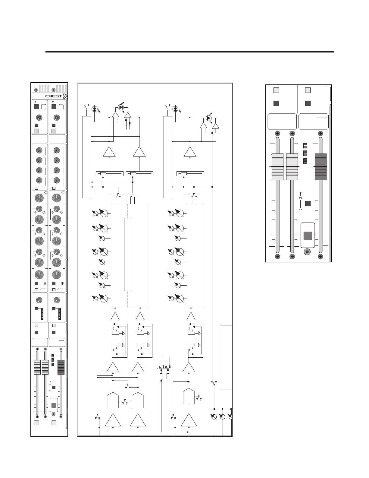
p. 68
4
X-VCA owner’s manual
left / right & mono masters
module
panel
TALK TO
MONO
TALK TO
L/R
SUM
L/R
L/R TO
MONO
5
10
0
5
10
20
30
15
50
5
10
0
5
10
20
30
15
50
PK
SIG
L
R
M
EDIT
CHAN
VCA ASN
VCA
ASSIGN
FOLLOW
SCENE
SELECT A
–
CHANNEL
–
TO ASSIGN
SINGLE
MONO
CENTER
RL
M
A
N
A
M
N
block diagram
MATRIX
IDENTICAL SETS OF MATRIX SENDS
M
S
A
M
A
N
U
A
L
M
U
T
E
S
C
E
N
E
S
SAFE
PREVIEW
MUTE
10
15
20
40
•
MATRIX
SENDS
10
20
30
40
•
10
20
30
40
•
10
20
30
40
•
10
20
30
40
•
MTX SENDS
POST LFT
HF HF
6K
3K
1.5
1K
1.5
HM
2K
1K
1.5
MID
1K
500
1.5
LM
300
120
200
LF
100
EQ
ON
L/R
–
OUTPUT LIMITER
–
3
RATIO=20:1
LIMIT
ON
(
)
RMS
L/R MONO
TALK TO
OUTPUT
–
0
10
TALK
SOLO
–
0
6
–
0
6
–
0
6
–
0
6
20K
.73
8K400
.73
4K200
.73
600
1.2K60
80040
40 HZ
24DB/OCT
+
6
2006
ATT
SUM
L/R
L/R
10
5
0
5
10
15
20
30
50
L/R
SOLO
MTX
1
LEV
+
5
TO
+
3
+
3
+
3
+
3
12K
18K
Q
4K
6K
Q
2K
3K
Q
1K
400
600
– +
FREQ
MAX
(
DBU
15
ON
1
3
6
9
12
18
24
(
DB
MUTE
20
40
MATRIX
SENDS
1
20
30
40
2
20
30
40
3
20
30
40
4
20
30
40
3K
1.5
1K
HM
1K
MID
500
LM
120
LF
100
MONO
OUTPUT LIMITER
)
LIMIT
(
RMS
)
RL
PK
L
R
M
SIG
VCA
ASSIGN
SINGLE
FOLLOW
SCENE
EDIT
CHAN
VCA ASN
SELECT A
–
CHANNEL
TO ASSIGN
PREVIEW
15
•
10
•
10
•
10
•
10
•
2K
1K
300
200
–
3
RATIO=20:1
ON
SAFE
10
–
10
TALK
SOLO
–
6
–
6
–
6
–
6
MTX SENDS
POST RT
6K
1.5
.73
1.5
.73
1.5
.73
EQ
ON
40 HZ
–
24DB/OCT
+
2006
)
ATT
L/R TO
MONO
TALK TO
MONO
CENTER
–
MONO
SOLO
MTX
2
OUTPUT
LEV
0
+
5
TO
1
0
+
3
2
0
+
3
3
0
+
3
4
0
+
3
12K
18K
20K
Q
4K
6K
8K400
Q
2K
3K
4K200
Q
600
1K
1.2K60
400
600
80040
– +
FREQ
MAX
(
)
6
DBU
15
ON
1
3
6
9
12
18
24
(
)
DB
MONO
10
5
0
5
10
15
20
30
50
L / R
SOLO
PK
SIG
LEFT POST
L / R
PRE-FADER
+10
LEFT
FADER
TO SOLO BUS & MICRO INTERFACE
FREQ
LEVEL
FREQ
LEVEL
FREQ
LEVEL
FREQ
LEVEL
FREQ
LEVEL
L / R
EQ ON
LF
40 - 800HZ
Q
3 - 0.7
Q
3 - 0.7
Q
3 - 0.7
LO MID
60 - 1.2KHZ
MID
200 - 4 KHZ
HI MID
400 - 8 KHZ
HF
1K - 20 KHZ
LEFT
INSERT
SEND RTN
L / R
STEREO 5-BAND SEMI-PARAMETRIC EQ
RIGHT
GC
L / R
SUM
HPF
ON
HPF
TALK TO L / R
X-VCA MASTER MODULE
∑
MIX AMPS
RIGHT POST
+10
PRE-FADER
RIGHT SIDE FOLLOWS LEFT
GC
HPF
HI-PASS FILTERS
∑
MONO
RIGHT
FADER
TO SOLO BUS & MICRO INTERFACE
FREQ
LEVEL
FREQ
LEVEL
Q
FREQ
LEVEL
Q
FREQ
LEVEL
Q
FREQ
LEVEL
LEFT POST
MONO
L / R TO
40HZ@24DB/OCT
TALK TO MONO
SOLO
MONO
EQ ON
3 - 0.7
3 - 0.7
3 - 0.7
MONO
INSERT
RIGHT POST
HI-PASS FILTER
40HZ@24DB/OCT
MONO POST
+10
MONO
LF
40 - 800HZ
LO MID
60 - 1.2KHZ
MID
200 - 4 KHZ
5-BAND SEMI-PARAMETRIC EQ
HI MID
400 - 8 KHZ
HF
1K - 20 KHZ
SEND RTN
GC
HPF
HPF
∑
MIX AMP
PK
FADER
ON
MONO
POST
MONO
PRE-FADER
M1
SIG
MONO TO MATRIX SENDS SHOWN.
LEFT AND RIGHT BOTH HAVE
MONO
M2
M3
Page 69

4
features
100mm Left,Right and Mono faders
These faders control the overall Left, Right and Mono master output levels. Note
that the Left, Right and Mono inserts are located prior to the faders and the limiters are located AFTER the faders.
vca assign switch
This switch makes it possible to include a snapshot of the consoles VCA assignements in each of the 128 micro mute scenes.
The VCA assignments function just as they do on a conventional VCA console. There is no connection between the VCA assignments and the micro mute
section.
Along with each of the 128 micro mute scenes, a snapshot of the consoles
VCA assignments is included.
For more information, see the section on VCA group assignments.
edit channel vca assign switch
Pressing this momentary switch puts the console into a VCA edit mode Edit by channel. This mode allows you to choose a channel, then decide what
VCA's it is assigned to.
For more information, see the section on VCA Group Operation.
l/r and mono solo switches
Pressing this momentary switch will include (illuminate) or exclude (not-illuminated) the channel from the consoles solo system.
See SOLO FEATURES section.
rear panel features
See the rear panel features for the Master control section.
p. 69
left / right & mono master modules
Page 70

p. 70
X-VCA owner’s manual
5
master control section
module
panel
40
15
10
0
10
•
5
20
+
–
SOLO
SAFE
PREVIEW
OUTPUT
LEV
40
15
10
0
10
•
5
20
+
–
SOLO
SAFE
PREVIEW
OUTPUT
LEV
MUTE MUTE
MTX
3
MTX
4
TALK
TO
TALK
TO
40
15
10
0
10
•
5
20
+
–
SOLO
SAFE
PREVIEW
OUTPUT
LEV
40
15
10
0
10
•
5
20
+
–
SOLO
SAFE
PREVIEW
OUTPUT
LEV
MUTE MUTE
MTX
3
MTX
4
TALK
TO
TALK
TO
40
20
10
0
6
•
3
30
+
–
40
20
10
0
6
•
3
30
+
–
40
20
10
0
6
•
3
30
+
–
40
20
10
0
6
•
3
30
+
–
MATRIX
SENDS
MATRIX
SENDS
40
20
10
0
6
•
3
30
+
–
40
20
10
0
6
•
3
30
+
–
MTX SENDS
POST MONO
2
3
40
20
10
0
6
•
3
30
+
–
40
20
10
0
6
•
3
30
+
–
MTX 1 IN
TO ALL 4
2
3
TB MIC
LF
HF
0
1515
88
+–
0
1515
88
+–
40
15
10
0
10
•
5
20
+
–
LEV
SOLO
PK
SIG
MONO
L-R
ASSIGN
HEADPHONES
ALT OUT
MONITOR
OUT
SOLO
OFF
1
357
10
0
9
28
6
4
1
357
10
0
9
28
6
4
PRE FDR
FROM
L/R/M
TALK
TO
SUM
MONO
TALK
TO
SUM
MONO
1
4
1
4
SOLO
ACTIVE
CLEAR
LCR TO
OUTPUTS
TB
ON
PINK
NOISE
SOLO CONTROL
TALKBACK CTRL HEADPHONES
(
TAP TO LATCH
)
ADDS MONO TO
ALT/MON/PHONES
1
357
10
0
9
28
6
4
11
1
3
5
7
10
0
92
8
6
4
SOURCE
MODE
POST FDR
PRE FDR
LAST PRESS
ADDITIVE
LEV LEV
EXTERNAL
STEREO
PGM INPUT
LEV LEV
SINGLE
SCENE
EDIT
PREVIEW
MICRO
UTILITY
EDIT
SAFE
HEADPHONE AND TALKBACK JACKS
LOCATED BELOW ARMREST
SEQUENCED
SCENE
8
6
4
5
3
1
2
7
M
A
N
U
A
L
M
U
T
E
S
C
E
N
E
S
GO
SEQUENCE
SCENE ON
128
block diagram
N
S
L
MO
PO
R
MATRIX
BAL OUT
SAFE
PRVW
SOLO
EXT STR PGM
SHELVING EQ
STEREO 2-BAND
TO SOLO BUS
MONO
ASSIGN
EXT STR PGM
RO
TER
ER-
E
UP
T &
RD
POST
MATRIX
+10
MUTE
MATRIX
(MICRO CONTROLLED)
MUTE AND SOLO SWITCHING
TO SOLO BUS & MICRO INTERFACE
SOLO MUTE
MATRIX
TALK TO
TB
FEED
CARDS
MATRIX CIRCUITRY 1 OF 4 SHOWN
LEVEL
MATRIX
PRE
MATRIX
MIX AMP
MIX
MATRIX
-
TO
SIDE
RIGHT
∑
INPUT
MICRO
ROL
Page 71
5
p. 71
master control section
features
The Master control section offers some flexible signal routing solutions as well as
utilitarian functions.Also included is the Microprocessor section, which is
described separately in it's own chapter.The master control section includes the
following features:
* Matrix Output Control
* Matrix Send 1 though 4
* External stereo program input with EQ
* Talkback input and control
* Alternate output and Monitor output control
* Headphone and solo control features
Matrix output control
The the master control section contains Matrix Masters 3 and 4.
mute
Mute switch
See LOCAL MICROPROCESSOR CONTROL section
Matrix master output level
The MATRIX MASTER output level controls set the levels that appear at
the corresponding MATRIX output connectors on the rear-panel.
Talk to
Adds the TALKBACK system output to the associated MATRIX output.The
level of the TALKBACK signal is set by the TALKBACK level control in the MASTER section.
solo switch
Pressing this momentary switch will include (illuminate) or exclude (not-illu-
minated) the channel from the consoles solo system.
See SOLO FEATURES section.
write-in label
This label may be written on with a grease-marker, or dry-erase pen and later
wiped clean. Masking tape may also be placed on this surface, if desired. If you
write on it with a "Sharpie", you may have trouble getting the writing off. If this is
the case, your best bet is to wipe the label off with isopropyl (rubbing) alcohol.
Page 72

p. 72
X-VCA owner’s manual
5
master control section
module
panel
40
20
10
0
6
•
3
30
+
–
40
20
10
0
6
•
3
30
+
–
40
20
10
0
6
•
3
30
+
–
40
20
10
0
6
•
3
30
+
–
MATRIX
SENDS
MATRIX
SENDS
40
20
10
0
6
•
3
30
+
–
40
20
10
0
6
•
3
30
+
–
MTX SENDS
POST MONO
2
3
40
20
10
0
6
•
3
30
+
–
40
20
10
0
6
•
3
30
+
–
MTX 1 IN
TO ALL 4
2
3
1
4
1
4
40
15
10
0
10
•
5
20
+
–
SOLO
SAFE
PREVIEW
OUTPUT
LEV
40
15
10
0
10
•
5
20
+
–
SOLO
SAFE
PREVIEW
OUTPUT
LEV
MUTE MUTE
MTX
3
MTX
4
TALK
TO
TALK
TO
40
20
10
0
6
•
3
30
+
–
40
20
10
0
6
•
3
30
+
–
40
20
10
0
6
•
3
30
+
–
40
20
10
0
6
•
3
30
+
–
MATRIX
SENDS
MATRIX
SENDS
40
20
10
0
6
•
3
30
+
–
40
20
10
0
6
•
3
30
+
–
MTX SENDS
POST MONO
2
3
40
20
10
0
6
•
3
30
+
–
40
20
10
0
6
•
3
30
+
–
MTX 1 IN
TO ALL 4
2
3
TB MIC
LF
HF
0
1515
88
+–
0
1515
88
+–
40
15
10
0
10
•
5
20
+
–
LEV
SOLO
PK
SIG
MONO
L-R
ASSIGN
HEADPHONES
ALT OUT
MONITOR
OUT
SOLO
OFF
1
357
10
0
9
28
6
4
1
357
10
0
9
28
6
4
PRE FDR
FROM
L/R/M
TALK
TO
SUM
MONO
TALK
TO
SUM
MONO
1
4
1
4
SOLO
ACTIVE
CLEAR
LCR TO
OUTPUTS
TB
ON
PINK
NOISE
SOLO CONTROL
TALKBACK CTRL HEADPHONES
(
TAP TO LATCH
)
ADDS MONO TO
ALT/MON/PHONES
1
357
10
0
9
28
6
4
11
1
3
5
7
10
0
92
8
6
4
SOURCE
MODE
POST FDR
PRE FDR
LAST PRESS
ADDITIVE
LEV LEV
EXTERNAL
STEREO
PGM INPUT
LEV LEV
SINGLE
SCENE
EDIT
PREVIEW
MICRO
UTILITY
EDIT
SAFE
HEADPHONE AND TALKBACK JACKS
LOCATED BELOW ARMREST
SEQUENCED
SCENE
8
6
4
5
3
1
2
7
M
A
N
U
A
L
M
U
T
E
S
C
E
N
E
S
GO
SEQUENCE
SCENE ON
128
block diagram
L/R
1
2
3
4
EXT MATRIX IN
INTERNAL MATRIX 1-4
EXT INPUT 1 ALSO FEEDS
BALANCED INPUTS TO FEED
MATRIX EXPANSION CONNECTOR
MONO TO MATRIX SENDS SHOWN.
LEFT AND RIGHT BOTH HAVE
IDENTICAL SETS OF MATRIX SENDS
POST
MONO
M1
M2
AND SWITCHES
MONO
SENDS
MATRIX
M3
M4
EXT IN 1
TO EXT MTX
TO ALL
M1
TO EXT MTX
M2
M3
M4
PK
EXT MATRIX IN
MATRIX SENDS
TO
SIDE
LEFT
SOLO LEFT
SOLO RIGHT
∑
LAST
SOLO
ACTIVE
∑
L & STATUS
CLEAR
POST
FADER
PRESSED
Page 73
p. 73
5
matrix sends
The master control section contains two sets of Matrix sends.The first set is used
to dial the Mono master signal into the four matrix busses.The second set is used
to dial external signals into the four matrix busses.
mono matrix 1–4 sends
These level controls are used to dial the MONO signal into the correspond-
ing matrix busses.
matrix sends post mono
MONO fader setting has no effect on the group-to-matrix level controls
1–4.
The MONO fader is introduced into the signal path and will control the signal level.When MONO is muted, the MONO signal to matrix 1-4 is muted as
well.
external input to matrix 1–4 sends
On the rear panel there are four balanced 1/4" TRS connectors.They are
labeled Matrix 1 through 4, one input for each matrix bus.These level controls are
used to dial external sources into the corresponding matrix.
matrix 1 in to all 4 switch
The signals fed into the four external matrix inputs appear at their corresponding matrix 1-4 pots, ready to be dialed onto the four matrix buses.
The signal fed into external matrix input 1 is routed to each of the matrix 14 pots, ready to be dialed into the four matrix busses. Signals fed into matrix
inputs 2, 3 and 4 are disregarded.
master control section
Page 74

p. 74
X-VCA owner’s manual
5
master control section
module
panel
Q
12K
20K
18K
TB M
LF
HF
0
1515
88
+–
0
1515
88
+–
40
15
10
0
10
•
5
20
+
–
LEV
4K
8K
6K
Q
2K
4K
3K
SOLO
PK
SIG
MONO
L-R
ASSIGN
HEADPHO
Q
600
EXTERNAL
STEREO
PGM INPUT
40
15
10
0
10
•
5
20
+
–
SOLO
SAFE
PREVIEW
OUTPUT
LEV
40
15
10
0
10
•
5
20
+
–
SOLO
SAFE
PREVIEW
OUTPUT
LEV
MUTE MUTE
MTX
3
MTX
4
TALK
TO
TALK
TO
40
20
10
0
6
•
3
30
+
–
40
20
10
0
6
•
3
30
+
–
40
20
10
0
6
•
3
30
+
–
40
20
10
0
6
•
3
30
+
–
MATRIX
SENDS
MATRIX
SENDS
40
20
10
0
6
•
3
30
+
–
40
20
10
0
6
•
3
30
+
–
MTX SENDS
POST MONO
2
3
40
20
10
0
6
•
3
30
+
–
40
20
10
0
6
•
3
30
+
–
MTX 1 IN
TO ALL 4
2
3
TB MIC
LF
HF
0
1515
88
+–
0
1515
88
+–
40
15
10
0
10
•
5
20
+
–
LEV
SOLO
PK
SIG
MONO
L-R
ASSIGN
HEADPHONES
ALT OUT
MONITOR
OUT
SOLO
OFF
1
357
10
0
9
28
6
4
1
357
10
0
9
28
6
4
PRE FDR
FROM
L/R/M
TALK
TO
SUM
MONO
TALK
TO
SUM
MONO
1
4
1
4
SOLO
ACTIVE
CLEAR
LCR TO
OUTPUTS
TB
ON
PINK
NOISE
SOLO CONTROL
TALKBACK CTRL HEADPHONES
(
TAP TO LATCH
)
ADDS MONO TO
ALT/MON/PHONES
1
357
10
0
9
28
6
4
11
1
3
5
7
10
0
92
8
6
4
SOURCE
MODE
POST FDR
PRE FDR
LAST PRESS
ADDITIVE
LEV LEV
EXTERNAL
STEREO
PGM INPUT
LEV LEV
SINGLE
SCENE
EDIT
PREVIEW
MICRO
UTILITY
EDIT
SAFE
HEADPHONE AND TALKBACK JACKS
LOCATED BELOW ARMREST
SEQUENCED
SCENE
8
6
4
5
3
1
2
7
M
A
N
U
A
L
M
U
T
E
S
C
E
N
E
S
GO
SEQUENCE
SCENE ON
128
block diagram
M
L
MONO
R
L
L /
LEFT
POST
POST
RIGHT
3
4
EXT MATRIX IN
HFLF
L
R
PROGRAM IN
EXTERNAL STEREO
SHELVING EQ
STEREO 2-BAND
LEVEL
STR PGM
SOLO
EXT STR PGM
TO SOLO BUS
MATRIX
MATRIX
MATRIX
LEVEL
MATRIX
BAL OUT
POST
+10
MUTE
MATRIX CIRCUITRY 1 OF 4 SHOWN
PRE
MATRIX
MIX AMP
MIX
MATRIX
E
HT
UT
∑
RO
M3
M4
PK
EXT MATRIX IN
MATRIX SENDS
L / R
SIG
MONO
ASSIGN
EXT STR PGM
E
UP
DS
RO
FT
Page 75

p. 75
master control section
5
external stereo program input
The external stereo program input allows a line level stereo source to be fed into
the console, eq'd and routed to the Left/Right and mono busses.The stereo
source can also be monitored through the solo system.This section can be used
for stereo returns or for stereo playback through the mains.
external stereo pro gram input eq
The stereo source passes through a basic eq section.The eq controls affect both
the left and right signals together.
HF EQ
15db boost or cut at 12kHz with shelving characteristics
LF EQ
15db boost or cut at 80Hz with shelving characteristics
program level control
Adjusts the level of the external stereo program input signal.
mono assignment switch
The post-level pot external stereo program signals are summed together as
a mono signal and are assigned to the mono mix buss with this switch.
L-R assignment switch
The post-level pot external stereo program signals are assigned to the left
and right mix busses with this switch.
peak/signal bi-color LED indicator
This bi-color LED indicates both peak and signal present conditions. External
program input levels within 3dB of overload will cause the RED peak LED to illuminate. (If this should occur beyond an occasional flicker, the external input level
should be reduced.) Green illumination of the LED indicates signal is present,and
it varies in brightness in response to varying signal levels.
external program Solo switch
See section on Solo features for more information.
LED
Page 76

p. 76
module
panel
SOLO
SIG
7
Q
ALT OUT
MON
O
SOL
OF
1
357
10
0
9
28
6
4
1
3
5
10
0
2
6
4
PRE FDR
FROM
L/R/M
TALK
TO
SUM
MONO
TAL
TO
SU
MON
400
800
600
FREQ
– +
6
15
MAX
(
DBU
)
600
1.2K
1K
/
OCT
40 HZ
TALKBACK CTRL HEADPHON
1
357
10
0
9
28
6
4
11
1
3
5
7
1
0
2
6
4
LEV
STEREO
PGM INPUT
LEV
40
15
10
0
10
•
5
20
+
–
SOLO
SAFE
PREVIEW
OUTPUT
LEV
40
15
10
0
10
•
5
20
+
–
SOLO
SAFE
PREVIEW
OUTPUT
LEV
MUTE MUTE
MTX
3
MTX
4
TALK
TO
TALK
TO
40
20
10
0
6
•
3
30
+
–
40
20
10
0
6
•
3
30
+
–
40
20
10
0
6
•
3
30
+
–
40
20
10
0
6
•
3
30
+
–
MATRIX
SENDS
MATRIX
SENDS
40
20
10
0
6
•
3
30
+
–
40
20
10
0
6
•
3
30
+
–
MTX SENDS
POST MONO
2
3
40
20
10
0
6
•
3
30
+
–
40
20
10
0
6
•
3
30
+
–
MTX 1 IN
TO ALL 4
2
3
TB MIC
LF
HF
0
1515
88
+–
0
1515
88
+–
40
15
10
0
10
•
5
20
+
–
LEV
SOLO
PK
SIG
MONO
L-R
ASSIGN
HEADPHONES
ALT OUT
MONITOR
OUT
SOLO
OFF
1
357
10
0
9
28
6
4
1
357
10
0
9
28
6
4
PRE FDR
FROM
L/R/M
TALK
TO
SUM
MONO
TALK
TO
SUM
MONO
1
4
1
4
SOLO
ACTIVE
CLEAR
LCR TO
OUTPUTS
TB
ON
PINK
NOISE
SOLO CONTROL
TALKBACK CTRL HEADPHONES
(
TAP TO LATCH
)
ADDS MONO TO
ALT/MON/PHONES
1
357
10
0
9
28
6
4
11
1
3
5
7
10
0
92
8
6
4
SOURCE
MODE
POST FDR
PRE FDR
LAST PRESS
ADDITIVE
LEV LEV
EXTERNAL
STEREO
PGM INPUT
LEV LEV
SINGLE
SCENE
EDIT
PREVIEW
MICRO
UTILITY
EDIT
SAFE
HEADPHONE AND TALKBACK JACKS
LOCATED BELOW ARMREST
SEQUENCED
SCENE
8
6
4
5
3
1
2
7
M
A
N
U
A
L
M
U
T
E
S
C
E
N
E
S
GO
SEQUENCE
SCENE ON
128
block diagram
A
I
O
T
X-VCA owner’s manual
5
master control section
X-VCA M
ALTERNATE OUT
LEFT RIGHT
M2M1
SUM
MONO
ALT OUT
LEVEL
TALK TO
ALT OUT
TALKBACK
AUDIO
PRE FDR
TB AUD
(TO RIBB
L R
POST MON
SOURCE
MONITOR FEEDS
TO OUTPUTS
LCR TO
OUTPUTS
POST PRE
MONO
L R
POST MON
SOURCE
LEFT RIGHT
POST FADER
SIGNAL SOURCES
FROM L / R / MONO
PRE MON
SOURCE
L R
L R
PRE MON
SOURCE
LEFT RIGHT
PRE FADER
PINK
NOISE
GEN
Page 77

p. 77
master control section
5
alternate output features
Additional outputs are available beyond matrix and headphone outputs.
These outputs are derived from the left, right and mono mix outputs (see
LCR to outputs switch).The outputs are available on the rear panel via male
XLR connectors.
LCR to outputs switch
Adds the Mono/Center signal to all master section control outputs as
a phantom center. This includes the Alternate Outputs, Monitor Outputs,
and Headphone Outputs of the console. In addition, it includes the
Mono/Center signal in the mono assisted listening output.
alt out (from L/R/M)
A pair of extra outputs for getting the Left, Right and mono signals out of the
console.
alternate output PRE FDR switch
Left / Right and mono signals are derived after their designated master
faders.
Left / Right and mono signals are derived before their designated master
faders.
alternate output level control
This pot controls the level that appears alternate output XLR's on the rear
panel.
Talk to
Adds the TALKBACK system output to the associated alternate outputs.
The level of the TALKBACK signal is set by the TALKBACK level control in the
MASTER section.
Sum Mono
The left and right signals are summed to mono.The Alt out Left and Right
XLRs on the rear panel carry the same mono signal.
The left and right signals stay separate, and appear separately at the Alt out
Left and Right XLRs on the rear panel.
Page 78

p. 78
module
panel
SOLO
ALT OUT
MONITOR
OUT
SOLO
OFF
7
10
9
8
6
1
357
10
0
9
28
6
4
PRE FDR
FROM
L/R/M
TALK
TO
SUM
MONO
TALK
TO
SUM
MONO
7
10
9
8
6
11
1
3
5
7
10
0
92
8
6
4
LEV LEV
LEV LEV
40
15
10
0
10
•
5
20
+
–
SOLO
SAFE
PREVIEW
OUTPUT
LEV
40
15
10
0
10
•
5
20
+
–
SOLO
SAFE
PREVIEW
OUTPUT
LEV
MUTE MUTE
MTX
3
MTX
4
TALK
TO
TALK
TO
40
20
10
0
6
•
3
30
+
–
40
20
10
0
6
•
3
30
+
–
40
20
10
0
6
•
3
30
+
–
40
20
10
0
6
•
3
30
+
–
MATRIX
SENDS
MATRIX
SENDS
40
20
10
0
6
•
3
30
+
–
40
20
10
0
6
•
3
30
+
–
MTX SENDS
POST MONO
2
3
40
20
10
0
6
•
3
30
+
–
40
20
10
0
6
•
3
30
+
–
MTX 1 IN
TO ALL 4
2
3
TB MIC
LF
HF
0
1515
88
+–
0
1515
88
+–
40
15
10
0
10
•
5
20
+
–
LEV
SOLO
PK
SIG
MONO
L-R
ASSIGN
HEADPHONES
ALT OUT
MONITOR
OUT
SOLO
OFF
1
357
10
0
9
28
6
4
1
357
10
0
9
28
6
4
PRE FDR
FROM
L/R/M
TALK
TO
SUM
MONO
TALK
TO
SUM
MONO
1
4
1
4
SOLO
ACTIVE
CLEAR
LCR TO
OUTPUTS
TB
ON
PINK
NOISE
SOLO CONTROL
TALKBACK CTRL HEADPHONES
(
TAP TO LATCH
)
ADDS MONO TO
ALT/MON/PHONES
1
357
10
0
9
28
6
4
11
1
3
5
7
10
0
92
8
6
4
SOURCE
MODE
POST FDR
PRE FDR
LAST PRESS
ADDITIVE
LEV LEV
EXTERNAL
STEREO
PGM INPUT
LEV LEV
SINGLE
SCENE
EDIT
PREVIEW
MICRO
UTILITY
EDIT
SAFE
HEADPHONE AND TALKBACK JACKS
LOCATED BELOW ARMREST
SEQUENCED
SCENE
8
6
4
5
3
1
2
7
M
A
N
U
A
L
M
U
T
E
S
C
E
N
E
S
GO
SEQUENCE
SCENE ON
128
block diagram
M
O
T
X-VCA owner’s manual
5
master control section
(LOWER AREA)
M3 M4
TALK TO
MONITOR
TALKBACK
AUDIO
TAP TO
LATCH
-
HOLD FOR
MOMENTARY
BACK
VOLT
/ ON
JACKS LOCATED ON MASTER MODULE
AND UNDER ARMREST
TALK BACK
IN
MONITOR OUT
LEFT RIGHT
SUM
MONO
L R
PRE MON
SOURCE
L R
POST MON
SOURCE
HEADPHONE
OUT
MONITOR
LEVEL
LEFT - RIGHT
SOLO
AUDIO
SOLO
OFF
HP
LEVEL
SOLO
CTRL
SOLO
AUDI
M
A
N
U
A
L
M
U
T
E
S
C
E
N
E
S
Page 79

p. 79
5
alternate output features
Monitor out
The Monitor out is very similar to the Alt out. Instead of assigning the Left and
Right signals to the monitor out, they are always assigned.When the LCR to
Outputs switch is depressed, the Mono master signal appears at the Monitor outputs, as well (see above).The solo signal can also appear at the Monitor outputs
(see below).
solo off switch
When anything on the console is solo'd, the solo signal appears at the
Monitor output and the Left/Right (plus mono/center if selected) signals are
muted.When solo is disengaged, the Left/Right (plus mono/center if selected) signals return.
When selected, the solo system no baring on the Monitor outputs.The
Left/Right (plus mono/center if selected) signals are not interrupted. When solo
off is selected, this output may be used as an additional set of post fader stereo
program outputs.
monitor output level control
Controls the output levels feeding the monitor output XLR connectors.
talk to
Adds the TALKBACK system output to the associated alternate outputs.
The level of the TALKBACK signal is set by the TALKBACK level control in the
MASTER section.
Sum Mono
The left and right signals are summed to mono.The Monitor out Left and
Right XLRs on the rear panel carry the same mono signal.
The left and right signals stay separate, and appear separately at the Monitor
out Left and Right XLRs on the rear panel.
master control section
Page 80
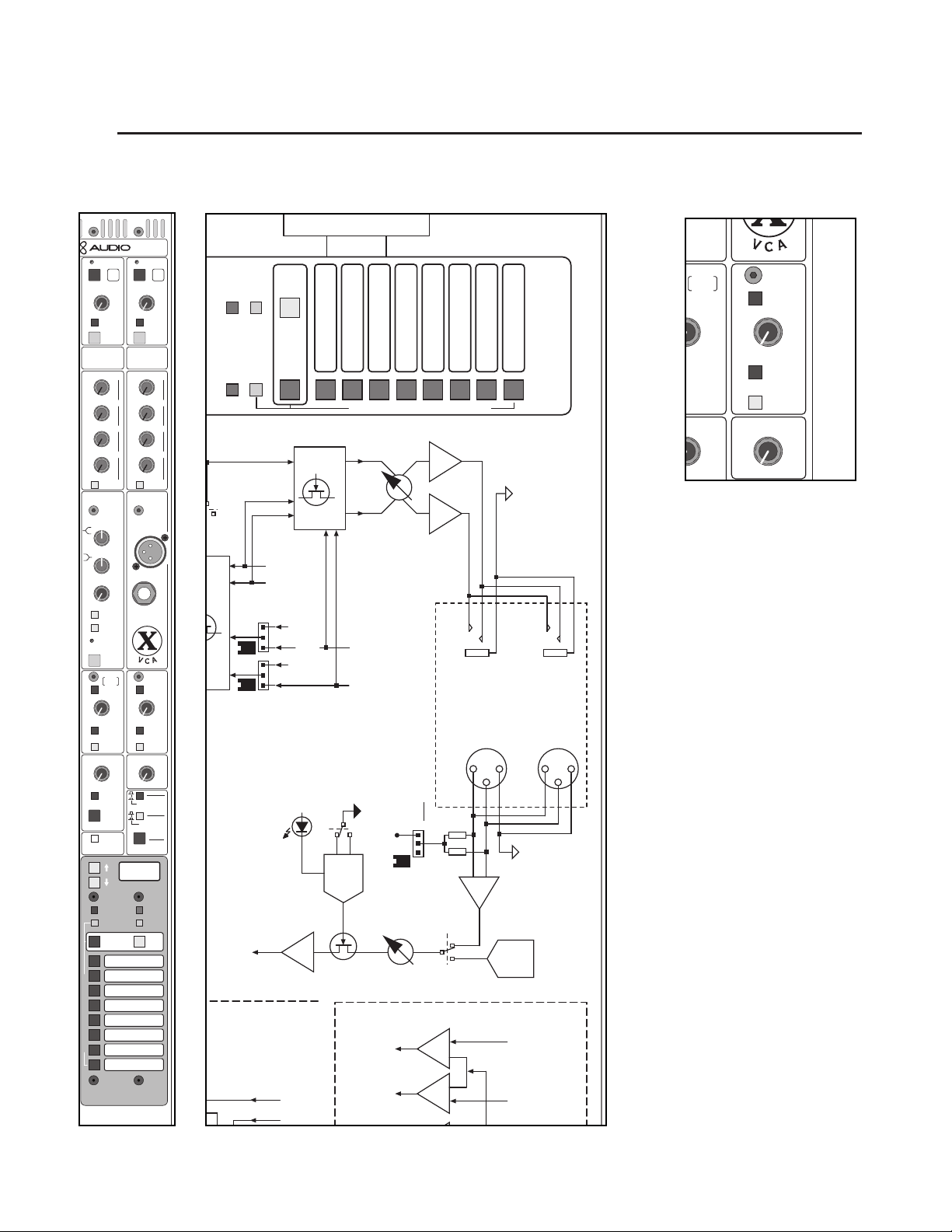
p. 80
X-VCA owner’s manual
5
master control section
module
panel
SOLO
ALT OUT
MONITOR
OUT
SOLO
OFF
7
10
9
8
6
1
357
10
0
9
28
6
4
PRE FDR
FROM
L/R/M
TALK
TO
SUM
MONO
TALK
TO
SUM
MONO
7
10
9
8
6
11
1
3
5
7
10
0
92
8
6
4
LEV LEV
LEV LEV
40
15
10
0
10
•
5
20
+
–
SOLO
SAFE
PREVIEW
OUTPUT
LEV
40
15
10
0
10
•
5
20
+
–
SOLO
SAFE
PREVIEW
OUTPUT
LEV
MUTE MUTE
MTX
3
MTX
4
TALK
TO
TALK
TO
40
20
10
0
6
•
3
30
+
–
40
20
10
0
6
•
3
30
+
–
40
20
10
0
6
•
3
30
+
–
40
20
10
0
6
•
3
30
+
–
MATRIX
SENDS
MATRIX
SENDS
40
20
10
0
6
•
3
30
+
–
40
20
10
0
6
•
3
30
+
–
MTX SENDS
POST MONO
2
3
40
20
10
0
6
•
3
30
+
–
40
20
10
0
6
•
3
30
+
–
MTX 1 IN
TO ALL 4
2
3
TB MIC
LF
HF
0
1515
88
+–
0
1515
88
+–
40
15
10
0
10
•
5
20
+
–
LEV
SOLO
PK
SIG
MONO
L-R
ASSIGN
HEADPHONES
ALT OUT
MONITOR
OUT
SOLO
OFF
1
357
10
0
9
28
6
4
1
357
10
0
9
28
6
4
PRE FDR
FROM
L/R/M
TALK
TO
SUM
MONO
TALK
TO
SUM
MONO
1
4
1
4
SOLO
ACTIVE
CLEAR
LCR TO
OUTPUTS
TB
ON
PINK
NOISE
SOLO CONTROL
TALKBACK CTRL HEADPHONES
(
TAP TO LATCH
)
ADDS MONO TO
ALT/MON/PHONES
1
357
10
0
9
28
6
4
11
1
3
5
7
10
0
92
8
6
4
SOURCE
MODE
POST FDR
PRE FDR
LAST PRESS
ADDITIVE
LEV LEV
EXTERNAL
STEREO
PGM INPUT
LEV LEV
SINGLE
SCENE
EDIT
PREVIEW
MICRO
UTILITY
EDIT
SAFE
HEADPHONE AND TALKBACK JACKS
LOCATED BELOW ARMREST
SEQUENCED
SCENE
8
6
4
5
3
1
2
7
M
A
N
U
A
L
M
U
T
E
S
C
E
N
E
S
GO
SEQUENCE
SCENE ON
128
block diagram
A
M
N
F
C
O
I
M
EDIT
SAFE
EDIT
PREVIEW
MICRO
UTILITY
SCENE
SINGLE
GO
SCENE ON
SEQUENCE
SOLO
AUDIO
1
2
M
ANU
HP
IN
3
L
A
LEVEL
G
C
4
M
6
5
T
E
SCENE
U
8
7
S
MICRO MUTE CONTROL
LEFT - RIGHT
OUT
SOURCE
L R
PRE MON
SOURCE
L R
POST MON
HEADPHONE
AND UNDER ARMREST
-
LATCH
TAP TO
HOLD FOR
MOMENTARY
TALK BACK
TALK ON
TB
LOGIC
SWITCH
+48V
TB
TB
TB AUDIO
(TO RIBBON)
L R
SOURCE
PRE MON
E MON
OURCE
L R
JACKS LOCATED ON MASTER MODULE
OFF / ON
+48 VOLT
PINK
LEVEL
NOISE
IN
TALK BACK
GEN
PINK
NOISE
LEFT RIGHT
PRE FADER
O
S
Page 81

p. 81
5
talkback and solo features
talkback control
The talkback section provides the facilities to take either an external input signal, or
an internally generated ping noise signal and route it to the consoles outputs.This is
useful for making announcements from the mix position and for performing system
diagnostics when other signal sources are not readily available.
Talkback control level
This control sets the level of the talkback signal,whether it is from the exter-
nal input or consists of the internal pink noise generator.
Pink noise
The talkback control section can get it's source signal from three places.The first
two are the female XLR mic inputs, one is located on the front panel in the Master
control section.The other is located below the consoles armrest, on the right side.
The third available source signal is the pink noise generator.The source is determined by the Pink Noise switch. For more information on the Talkback XLR mic
inputs, see the master control section rear panel descriptions.
The talkback control section gets it's source signal from either, or both of the
Talkback female XLR mic inputs.
The talkback control section gets it's source signal from the internal pink noise
generator.
TB ON - Talk back on
This "soft" switch activates the Talkback section.The Talkback section must be activate in order for any of it's features to work.
Tap switch once - This will toggle the Talkback section on and off.Tap once to
turn it on, when you're done tap it again to turn it off.
Press and hold - The switch works as a momentary button. Press it and hold it
for more than two seconds.While the button is down, the Talkback section is activated.When you release the button, the Talkback section shuts off.
Headphone level
This control sets the level that appears at the two headphone jacks. One jack
is located on the consoles front panel, next to the TB mic input, and the other jack is
located below the armrest.
LCR to Outputs button
The signals that appears at the Alt outs, the Monitor outs and the headphones
do not include the Mono, or center output signal.
The signals that appear at the Alt outs, the Monitor outs and the headphones
include the Mono, or center output signal.
master control section
Page 82
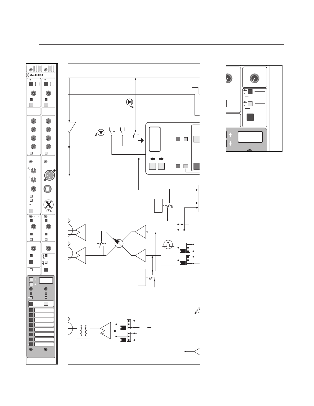
p. 82
X-VCA owner’s manual
5
master control section
SOLO
ACTIVE
CLEAR
LCR TO
OUTPUTS
TB
ON
PINK
NOISE
SOLO CONTROL
ACK CTRL HEADPHONES
)
MONO TO
5
7
10
9
8
6
11
1
3
5
7
10
0
92
8
6
4
SOURCE
MODE
POST FDR
PRE FDR
LAST PRESS
ADDITIVE
LEV LEV
SEQUENCED
SCENE
128
40
15
10
0
10
•
5
20
+
–
SOLO
SAFE
PREVIEW
OUTPUT
LEV
40
15
10
0
10
•
5
20
+
–
SOLO
SAFE
PREVIEW
OUTPUT
LEV
MUTE MUTE
MTX
3
MTX
4
TALK
TO
TALK
TO
40
20
10
0
6
•
3
30
+
–
40
20
10
0
6
•
3
30
+
–
40
20
10
0
6
•
3
30
+
–
40
20
10
0
6
•
3
30
+
–
MATRIX
SENDS
MATRIX
SENDS
40
20
10
0
6
•
3
30
+
–
40
20
10
0
6
•
3
30
+
–
MTX SENDS
POST MONO
2
3
40
20
10
0
6
•
3
30
+
–
40
20
10
0
6
•
3
30
+
–
MTX 1 IN
TO ALL 4
2
3
TB MIC
LF
HF
0
1515
88
+–
0
1515
88
+–
40
15
10
0
10
•
5
20
+
–
LEV
SOLO
PK
SIG
MONO
L-R
ASSIGN
HEADPHONES
ALT OUT
MONITOR
OUT
SOLO
OFF
1
357
10
0
9
28
6
4
1
357
10
0
9
28
6
4
PRE FDR
FROM
L/R/M
TALK
TO
SUM
MONO
TALK
TO
SUM
MONO
1
4
1
4
SOLO
ACTIVE
CLEAR
LCR TO
OUTPUTS
TB
ON
PINK
NOISE
SOLO CONTROL
TALKBACK CTRL HEADPHONES
(
TAP TO LATCH
)
ADDS MONO TO
ALT/MON/PHONES
1
357
10
0
9
28
6
4
11
1
3
5
7
10
0
92
8
6
4
SOURCE
MODE
POST FDR
PRE FDR
LAST PRESS
ADDITIVE
LEV LEV
EXTERNAL
STEREO
PGM INPUT
LEV LEV
SINGLE
SCENE
EDIT
PREVIEW
MICRO
UTILITY
EDIT
SAFE
HEADPHONE AND TALKBACK JACKS
LOCATED BELOW ARMREST
SEQUENCED
SCENE
8
6
4
5
3
1
2
7
M
A
N
U
A
L
M
U
T
E
S
C
E
N
E
S
GO
SEQUENCE
SCENE ON
128
∑
AUDIO
LR
SC
O
-
TO
SIDE
LEFT
MICRO
CARDS
GROUP
SOLO CONTROL & STATUS
SUM
SOLO
MONO
ACTIVE
CLEAR
LAST
POST
PRESSED
LEVEL
MONITOR
FADER
CTRL
SOLO
TALK TO
MONITOR
SOURCE
L R
PRE MON
128
SEQUENCED
OFF
SOLO
AUDIO
TALKBACK
SOURCE
L R
POST MON
SCENE
EDIT
SAFE
MICRO
EDIT
SINGLE
PREVIEW
TB AUDIO
(TO RIBBON)
GO
UTILITY
SCENE
SEQUENCE
SOLO
LEFT - RIGHT
N
ENE
TB
Page 83

p. 83
5
solo features
The X-VCA provides a powerful stereo solo system. Any input or output
can be monitored pre (PFL) or after level control (AFL), as desired. The
system may be additive (all channels selected on solo bus), or exclusive, so
that only one solo switch is active at a time ("last pressed").Any signal being
solo'd appears on the dedicated left and right solo meters, and is audible in
the stereo headphone system and the Monitor outputs (unless the SOLO
OFF button is pressed). Solo functions may be canceled by tapping any illuminated solo switch, or all solo switches may simultaneously be canceled
using the Solo Clear switch.
Solo Control
This covers the Solo Control features located in the Master section
post fader switch
Any input or output signal that is solo'd can be be derived before or after
it's main level control. In the case of Input channels this would be the channel fader and in the case of outputs this would be the output fader or
rotary pot.
Pre fader - Any input or output signal that is solo'd will be derived
before it's main level control.
Post fader - Any input or output signal that is solo'd will be derived
after it's main level control.
additive / last press pressed switch
The solo system has two modes - ADDITIVE and LAST PRESSED.
Additive - Multiple inputs/outputs can be solo'd at once.After soloing
one input or output, pressing subsequent channel solo switches will continue to add channels to the solo bus. Pressing any solo button that is already
activated will deactivate that solo.
Last Pressed - Only one solo can be activated at a time. Pressing
another solo button will clear the previous solo.
solo active / clear switch
This momentary, illuminated switch provides two functions.
1. Solo active - When any input/ouput on the console is solo'd, this switch it
lit up.
2. Clear - Pressing this switch will clear (shut off) any inputs/outputs on the
console that are solo'd.This is especially useful when the solo system is in
Additive mode, to clear multiple soloes with one button press
.
master control section
Page 84
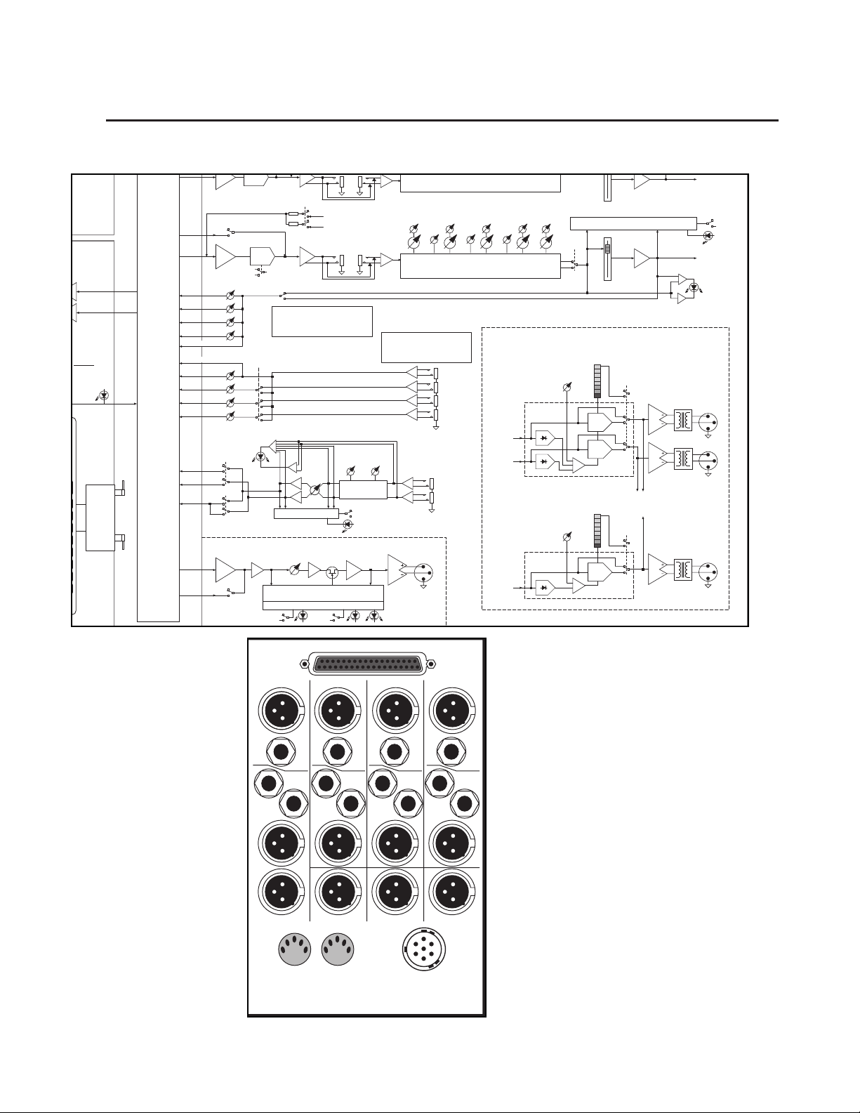
p. 84
X-VCA owner’s manual
5
master control section
∑
L / R
A
O
OL)
RS
SOLO LEFT
SOLO RIGHT
& STATUS
SOLO
ACTIVE
CLEAR
LAST
PRESSED
POST
FADER
MASTER
INPUT &
GROUP
CONTROL
L
MICRO
INTER-
FACE
CARD
HPF
HI-PASS FILTERS
40HZ@24DB/OCT
TALK TO MONO
TB
FEED
MONO
MIX
TO EXT MTX
TO EXT MTX
TO
LEFT
SIDE
-
GROUP
MICRO
CARDS
-
TO
RIGHT
SIDE
INPUT
MICRO
CARDS
-
MATRIX
FEED
MIX
TB
∑
MIX AMP
M1
M2
M3
M4
M1
M2
M3
M4
EXT MATRIX IN
MATRIX SENDS
L / R
MONO
EXT STR PGM
ASSIGN
MIX AMP
∑
TAL K TO
MATRIX
HI-PASS FILTER
40HZ@24DB/OCT
HPF
HPF
ON
MONO
MATRIX
SENDS
EXT IN 1
TO ALL
PK
SIG
GC
L / R TO
MONO
GC
POST
MONO
MONO TO MATRIX SENDS SHOWN.
LEFT AND RIGHT BOTH HAVE
IDENTICAL SETS OF MATRIX SENDS
AND SWITCHES
STR PGM
LEVEL
TO SOLO BUS
MATRIX CIRCUITRY 1 OF 4 SHOWN
MATRIX
LEVEL
MATRIX
PRE
MUTE AND SOLO SWITCHING
(MICRO CONTROLLED)
TO SOLO BUS & MICRO INTERFACE
SOLO MUTE
LEFT POST
RIGHT POST
MONO
INSERT
SEND RTN
MATRIX
MUTE
HFLF
STEREO 2-BAND
SHELVING EQ
EXT STR PGM
SOLO
MATRIX
POST
+10
RIGHT SIDE FOLLOWS LEFT
LEVEL
LEVEL
FREQ
FREQ
Q
3 - 0.7
HF
HI MID
1K - 20 KHZ
400 - 8 KHZ
5-BAND SEMI-PARAMETRIC EQ
BALANCED INPUTS TO FEED
INTERNAL MATRIX 1-4
EXT INPUT 1 ALSO FEEDS
MATRIX EXPANSION CONNECTOR
1
2
3
4
EXT MATRIX IN
EXTERNAL STEREO
PROGRAM IN
L
R
MATRIX
BAL OUT
SAFE
PRVW
Q
3 - 0.7
200 - 4 KHZ
PRE-FADER
LEVEL
LEVEL
Q
3 - 0.7
60 - 1.2KHZ
LO MID
FREQ
LEVEL
FREQ
LF
40 - 800HZ
TO SOLO BUS & MICRO INTERFACE
MONO
EQ ON
MONO
PRE-FADER
FREQ
MID
RIGHT
FADER
MONO
FADER
+10
RIGHT POST
MONO
SOLO
MONO POST
+10
PK
SIG
MAIN OUTPUT LIMITERS
OUTPUT
ATT EN U ATI O N
METER
OUTPUT
ON
1
LEVEL
3
6
9
12
18
24
VCA
VCA
OUTPUT
ATTENUATION
METER
ON
1
3
6
9
12
18
24
VCA
20 : 1
RATIO
20 : 1
RATIO
L / R
LIMITER ON
MONO
LIMITER ON
L / R
METER
SENDS
MONO
METER
SEND
XFORMER
OPTION
XFORMER
OPTION
LEFT
BAL OUT
RIGHT
MONO
BAL OUT
LEFT
POST
RIGHT
POST
MONO
POST
L / R STEREO
LIMITER
MONO
LIMITER
-6 DBU +20
OUTPUT
LEVEL
-6 DBU +20
Matrix 4 Matrix 3 Matrix 2 Matrix 1
Out
Out Out Out
Matrix
Expansion
In In In In
Ext Mon
Mon
Out
L
Mon
Out
R
Ext Mon
In L
In R
Return
Mono
Out
Insert
Send
Return
Right
Out
Insert
Send
Return
Left
Out
Insert
Send
Assist Out Alt R Out Alt L Out
DC In
MIDI
In Out
Page 85
p. 85
master control section
5
rear panel features
matrix expansion
The X-VCA offers a matrix expansion system. In additional to the four matrix
outputs available withing the console, the individual matrix feeds can be brought
out of the console and fed into an external matrix mixer, produced by Crest.This
matrix mixer is the X-Matrix, a single rack space unit that provides two additional
matrix mixes. Multiple X-Matrix units can be dasy-chained together for any number of additional matrix mixes. For more information see the section on XMatrix.
matrix expansion connector
A 37-pin D-Sub connector makes all of the matrix feeds available on the rear
panel.These signals can be fed to the Crest Audio X-Matrix unit, any other Matrix
mixer, or stand alone mixing board. Feeding these signals to a mixer other than
the X-Matrix requires a custom-terminated multi-pin cable that mates to this
connector.
The following feeds are available from the Matrix expansion connector:
1.Audio groups, 1 through 8
2. Left, Right and Mono masters
3. External Matrix In #1
3.Talk back audio signal
4. Solo audio signals
5. Solo control signal
6. Power feed, specifically configured to run X-Matrix units.
*All of the audio signals are balanced.
*The Matrix Pre/post buttons on the Groups and L/R/M masters apply to these
feeds, as well.
Matrix output connectors (1 through 4)
These balanced male XLR connectors carry the Matrix master outputs 1
through 4.
Matrix external input connectors (1 through 4)
These balanced TRS connectors allow external line level signals to be
added to the four Matrix busses.Their levels are controlled by the Matrix send
pots located in the master section. A signal fed into External Matrix 1 also gets
routed (after it's level control) to the Matrix expansion connector.
Page 86

p. 86
X-VCA owner’s manual
5
master control section
TALK TO AUX
ASSIGN
ONTROL
ITCHES
2468
UT
D)
S AS
W:
EVEL)-
S / RCA
ONTROL)
DICATORS
∑
SOLO LEFT
LO
IX
PS
SOLO RIGHT
∑
NTROL & STATUS
SOLO
ACTIVE
CLEAR
LAST
PRESSED
POST
FADER
8
NCED
NE
EDIT
SAFE
MICRO
UTILITY
GO
NTROL
MASTER
MICRO
INTER-
FACE
CARD
INPUT &
GROUP
CONTROL
GROUP
MICRO
CARDS
RIGHT
MICRO
CARDS
TO
LEFT
SIDE
TO
SIDE
INPUT
-
-
TB
FEED
X-VCA MASTER MODULE
TALK TO L / R
TB
FEED
LEFT
MIX
∑
HPF
MIX AMPS
MIX
TB
MIX
TO EXT MTX
TO EXT MTX
MIX
TB
∑
TALK TO MONO
∑
MIX AMP
M1
M2
M3
M4
M1
M2
M3
M4
EXT MATRIX IN
MATRIX SENDS
L / R
MONO
EXT STR PGM
ASSIGN
MIX AMP
∑
TALK TO
MATRIX
ON
HI-PASS FILTERS
40HZ@24DB/OCT
40HZ@24DB/OCT
RIGHT
FEED
MONO
MATRIX
FEED
HPF
SUM
L / R
HPF
HI-PASS FILTER
HPF
HPF
ON
POST
MONO
MONO TO MATRIX SENDS SHOWN.
LEFT AND RIGHT BOTH HAVE
MONO
MATRIX
IDENTICAL SETS OF MATRIX SENDS
SENDS
AND SWITCHES
EXT IN 1
TO ALL
PK
SIG
MATRIX CIRCUITRY 1 OF 4 SHOWN
MATRIX
PRE
TO SOLO BUS & MICRO INTERFACE
SOLO MUTE
INSERT
SEND RTN
GC
RIGHT
GC
L / R TO
MONO
LEFT POST
RIGHT POST
MONO
INSERT
SEND RTN
GC
STR PGM
LEVEL
TO SOLO BUS
MATRIX
MATRIX
LEVEL
MUTE
MUTE AND SOLO SWITCHING
(MICRO CONTROLLED)
LEFT
STEREO 2-BAND
SHELVING EQ
EXT STR PGM
SOLO
MATRIX
POST
+10
LEVEL
FREQ
3 - 0.7
HF
1K - 20 KHZ
LEVEL
FREQ
3 - 0.7
HF
1K - 20 KHZ
BALANCED INPUTS TO FEED
INTERNAL MATRIX 1-4
EXT INPUT 1 ALSO FEEDS
MATRIX EXPANSION CONNECTOR
EXT MATRIX IN
HFLF
EXTERNAL STEREO
PROGRAM IN
MATRIX
BAL OUT
SAFE
PRVW
LEVEL
LEVEL
FREQ
FREQ
Q
Q
Q
3 - 0.7
3 - 0.7
HI MID
MID
400 - 8 KHZ
200 - 4 KHZ
Q
3 - 0.7
200 - 4 KHZ
60 - 1.2KHZ
LEVEL
FREQ
Q
3 - 0.7
MID
60 - 1.2KHZ
STEREO 5-BAND SEMI-PARAMETRIC EQ
RIGHT SIDE FOLLOWS LEFT
LEVEL
FREQ
Q
HI MID
400 - 8 KHZ
5-BAND SEMI-PARAMETRIC EQ
1
2
3
4
LEFT
POST
RIGHT
POST
L
R
MONO
POST
LO MID
LO MID
LEVEL
FREQ
LEVEL
FREQ
LEVEL
FREQ
LF
40 - 800HZ
LEVEL
FREQ
LF
40 - 800HZ
L / R STEREO
LIMITER
MONO
LIMITER
TO SOLO BUS & MICRO INTERFACE
L / R
EQ ON
L / R
PRE-FADER
TO SOLO BUS & MICRO INTERFACE
MONO
EQ ON
MONO
PRE-FADER
MAIN OUTPUT LIMITERS
OUTPUT
ATTENUATION
OUTPUT
ON
1
LEVEL
3
-6 DBU +20
6
9
12
18
24
OUTPUT
ATTENUATION
OUTPUT
ON
1
LEVEL
3
-6 DBU +20
6
9
12
18
24
METER
METER
L / R
SOLO
LEFT POST
+10
LEFT
FADER
+10
RIGHT
FADER
+10
MONO
FADER
L / R
LIMITER ON
VCA
VCA
20 : 1
RATIO
L / R
METER
SENDS
MONO
METER
MONO
SEND
LIMITER ON
VCA
20 : 1
RATIO
L / R
PRE-FADER
RIGHT POST
MONO POST
XFORMER
OPTION
XFORMER
OPTION
PK
SIG
MONO
SOLO
PK
SIG
LEFT
BAL OUT
RIGHT
MONO
BAL OUT
Matrix 4 Matrix 3 Matrix 2 Matrix 1
Out
Out Out Out
In In In In
Ext Mon
In R
Mon
Out
L
Mon
Out
R
Ext Mon
In L
Return
Mono
Out
Insert
Send
Return
Right
Out
Insert
Send
Assist Out Alt R Out Alt L Out
MIDI
In Out
Return
Left
Out
Matrix
Expansion
DC In
Insert
Send
Page 87
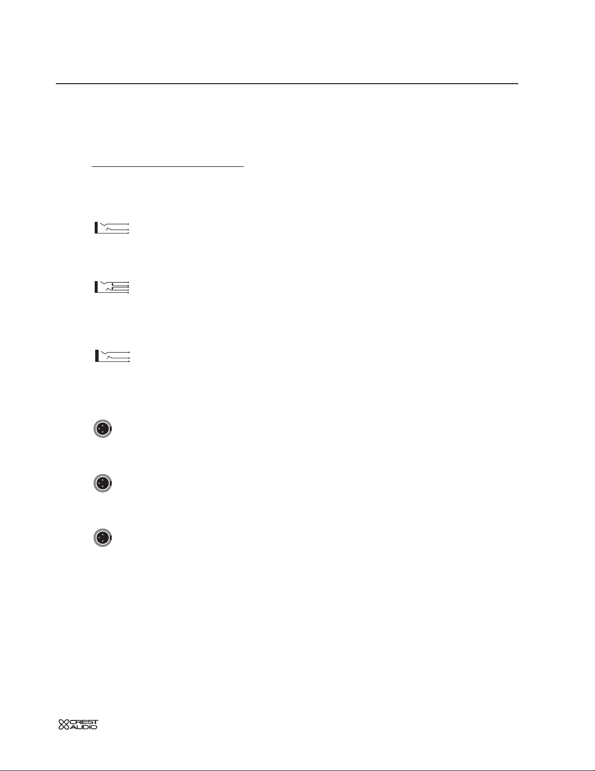
p. 87
5
rear panel features
Left, Right and Mono insert points
Separate send and return 1/4" TRS jacks are provided for inserting external signal
processors into the Left, Right and Mono outputs.The insert points are located
after the Low pass filters and before the EQ sections.
insert send
This jack serves as an output which gets patched to the input of a signal processor. Plugging a 1/4" TRS plug into this jack does not break the signal
flow of the master output..This output jack is ground-compensated.
insert return
The output of a signal processor is patched to jack. It can accept a balanced or unbalanced signal. Plugging a 1/4" TRS plug into this jack breaks the signal
flow of the master output.
Stereo Program In jacks (left and right)
These two (left and right) 1/4" TRS jacks are used to bring balanced or
unbalanced stereo signals into the Stereo Program In section.Typically, they can be
the return from a stereo signal processor or the output of a two track playback
device.
Left,Right and Mono master outputs
These three balanced male XLR connectors carry the Left, Right and Mono
outputs.
Monitor outputs (left and right)
These two balanced male XLR connectors carry the Left and Right Monitor
outputs 4.
Assist output
This balanced male XLR connector carries a signal that is made up of the
post fader Left and Right master outputs, summed together. Pressing the LCR to
Outputs button will add the Mono master output to this summed signal. Internal
jumpers can be set to make the master feeds pre fader instead of post fader.
Midi IN and OUT
These jacks allow the microprocessor system to communicate with MIDI gear.
See the section on the Microprocessor for more information.
DC In
This 7 pin connector is used to connect the power supply interconnect cable to
the console.
master control section
Page 88
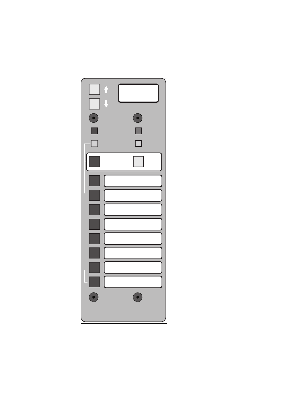
p. 88
X-VCA owner’s manual
6
microprocessor control
SINGLE
SCENE
EDIT
PREVIEW
MICRO
UTILITY
EDIT
SAFE
HEADPHONE AND TALKBACK JACKS
LOCATED BELOW ARMREST
SEQUENCED
SCENE
8
6
4
5
3
1
2
7
M
A
N
U
A
L
M
U
T
E
S
C
E
N
E
S
GO
SEQUENCE
SCENE ON
128
Page 89

p. 89
6
microprocessor control
microprocessor controlled muting
The Crest X-Series of Consoles* is equipped with a micro-controlled Mute Controller which permits the user to set-up a series
of Mute Scenes, each controlling any combination of channels and
outputs.These Scenes can then be recalled, either singly or in
combination, to allow the operator to easily control the mutes
during a performance.
The Mute Controller features 128 Sequenced Scenes (Patches)
along with 8 Manual Mute Scenes.The 128 Patches can be stepped
through using a single button, or remotely activated by the use of
MIDI patch-change commands.The Patches can be combined with
the Manual Scenes to allow different combinations of Channel
mutes.
The following is a overview of the controls and indicators of the
Mute Controller and the Channels (see diagrams on previous
page).The following information pertains to X-Eight consoles with
Rev 1.12 firmware, and X-Monitor consoles with Rev 1.00
firmware.
12-12-01 Supplementary information....
1) To perform “FULL FACTORY RESET” of Micro Mute and VCA
settings hold up/down buttons upon power-up. This will clear all
memory and restore Micro Controller to factory presets.
2) Do not use the "uP" parameter with the setting "OFF" in the utility
menu until a newer EPROM version is released. Please submit your
console serial # and shipping address to Roffi@CrestAudio.com if
you wish to be on an EPROM distribution list for this event.
3) EOF stands for Edit On the Fly. A new parameter offered in the
utility menu. When selected it allows for spontaneous removal of a
mute you have programmed in as part of a current scene.
Page 90

X-VCA owner’s manual
6
microprocessor control
mute control panel
typical input or output
Page 91

p. 91
microprocessor control
6
Mute controller
A)Up/Down
Each press of these switches increments or decrements the Patch Display
(B). Holding either button down will allow quickly scrolling up or down.The
buttons are also used to select the parameters and settings of the system
while in Utility mode.
B)Display
This 4-character alpha-numeric display normally shows the current Patch (1
through 128) being recalled. It is also used to display the parameters and
settings of the system while in Utility mode.
C)Edit Preview
Pressing this switch puts the system into Edit/Preview mode, allowing the
operator to view and change the contents of any selected Mute Scene.The
internal red LED will blink while in this mode, along with the status LEDs (J)
of any channels assigned to the selected Mute Scene. Pressing a Channel
Mute Sw (K) will add or remove a channel from that Scene. Pressing the
Edit/Preview switch again will exit back to normal operating mode.
D)Edit Safe
Pressing this switch puts the system into Edit Safe mode, allowing the operator to view and change the contents of the SAFE memory.The internal
green LED will blink while in this mode, along with any channels assigned to
the Safe Scene. Pressing a Channel Mute Sw (K) will add or remove a channel from the Safe Scene. If a channel is included in the Safe Scene, it can’t be
muted from a Mute Scene.This allows the operator to remove a channel all
Scenes without having to edit any of the Scenes themselves. Pressing the
Edit Safe switch again will exit back to normal operating mode.
E)Single Scene
There are 9 mute sources available from the Mute Controller: the 8 Manual
Mute Scenes (H), and the Micro Scene (G). Normally any or all of theses 9
sources can be active at one time, which allows the operator to combine
different mute patterns.The Single Scene switch, when depressed, permits
only 1 of the 9 sources to be active at one time.
F)Micro Utility
This latching switch will put the system into Utility mode.The operator can
then access and view the various parameters and functions of the controller
using the Up/Down buttons (A) and the Display (B).
G)Micro Scene
This switch activates the Sequenced Scene (Patch).The display (B) shows
which of the 128 possible Scenes are active.
H)Manual Mutes
These 8 switches activate the associated Manual Mute Scene.Additionally,
these switches, along with (G), select which Mute Scene is being edited
when in Edit Preview Mode.
Page 92

p. 92
X-VCA owner’s manual
6
microprocessor control
mute control panel
typical input or output
Page 93

p. 93
6
microprocessor control
Mute controller
I)Recall (Next)
Each press of this switch increments the Sequenced Mutes by one, the display (B) will reflect this.Also used to activate the displayed Scene when an
Up/Down (A) button was used to scroll to a new Scene. In this case, an "*"
will be displayed as the first character in the display to indicate that the displayed number is not currently the active Scene. Pressing Recall will put that
displayed Scene into place and clear the "*" from the display.
NOTE:All of the above actions will take place, but the displayed Sequenced
Scene will not be active (mutes not enabled) unless the Micro Scene switch
(G) is lit. Each press of these switches increments or decrements the Patch
Display (B). Holding either button down will allow quickly scrolling up or
down.The buttons are also used to select the parameters and settings of
the system while in Utility mode.
Page 94

p. 94
X-VCA owner’s manual
6
microprocessor control
mute control panel
typical input or output
Page 95

p. 95
6
microprocessor control
channel mute controls
J)Status LED
This bi-color LED, associated with each controlled Mute, shows the condition of that mute. One of 5 possible states is possible:
1)Off- The channel is not controlled by the Mute Controller.
2)Steady Red- The channel is being muted by a Mute Scene.
3)Steady Green- The channel is in Safe Mode, can’t be muted by any
Scene.
4)Blink Red- The system is in Edit Preview Mode and the channel is in the
currently selected Scene (only 1 Scene active at a time).
5)Blink Green- The system is in Edit Safe Mode and the channel is included in the Safe Scene.
K)Mute Switch
This momentary switch toggles the Channel’s local mute and is also used to
assign / un-assign channels to Mute and Safe Scenes when in the Edit Modes.
L)Mute LED
This internal Red LED will illuminate whenever the channel is muted, either
locally or by a Mute Scene.
NOTE: If a channel is already locally muted when a relevant Mute Scene is activated,
this LED will remain lit. 2 sources are now telling the channel to mute; the Local
Mute and the Mute Scene. If the Mute Sw (K) is pressed once, the local mute will be
cleared, but no apparent change will occur.The Mute LED (L) will still be lit, and the
Status LED (J) will still be steady Red.At this point there is only one source telling
the channel to mute; the Mute Scene. If the Mute Scene is then disabled, the channel
will un-mute because the Local Mute was previously cleared. The user should be
aware of this fact:The Local Mutes can toggle invisibly behind a Mute Scene. For an
even number of presses on the Mute Sw (K), the Local Mute will return to its original state, an odd number of presses will change the Local Mute to its opposite state.
Each press of this switch increments the Sequenced Mutes by one, the display (B)
will reflect this.Also used to activate the displayed Scene when an Up/Down (A)
button was used to scroll to a new Scene. In this case, an "*" will be displayed as the
first character in the display to indicate that the displayed number is not currently
the active Scene. Pressing Recall will put that displayed Scene into place and clear
the "*" from the display.
NOTE:All of the above actions will take place, but the displayed Sequenced Scene
will not be active (mutes not enabled) unless the Micro Scene switch (G) is lit. Each
press of these switches increments or decrements the Patch Display (B). Holding
either button down will allow quickly scrolling up or down.The buttons are also
used to select the parameters and settings of the system while in Utility mode.
Page 96
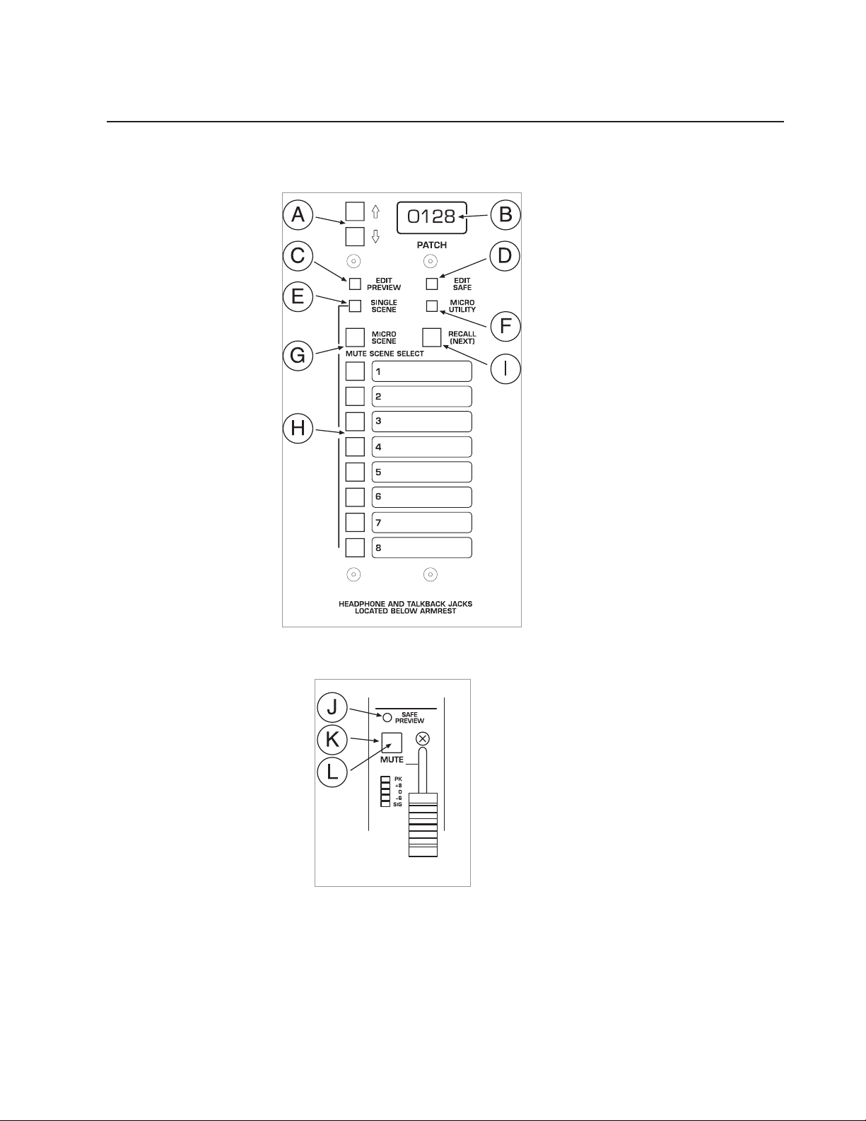
X-VCA owner’s manual
6
microprocessor control
p. 96
mute control panel
typical input or output
Page 97

p. 97
microprocessor control
6
mute scenes
There are 9 possible Scene sources: Manual Mute Scenes 1 thru 8, and the
Micro Scene.The Micro Scene button (G) is the enable switch for the 128
possible Sequenced Scenes.The 8 Manual Mutes are totally independent of
the 128 Sequenced Scenes, giving the system a total of 136 possible mute
patterns. Each of the 136 patterns can consist of any combination of
Channel and Output mutes, all of the 9 possible sources can be combined
to create additional patterns.
Creating a Mute Scene (or Editing an existing one):
1) Press the Edit Preview button (C), it will begin to blink, indicating that the
system is in Edit Preview Mode.
2) Select a Scene to Edit:The system will automatically choose a Scene to
edit, depending on the status of the system when Edit Preview was selected.
If the system was in Single Scene Mode (switch E depressed), the Mute
Scene that was currently active will be selected to edit. If the system was in
Multiple Scene Mode (switch E not depressed), the Micro Scene will be
automatically selected for editing. If a different Scene than the default is to
be edited, that scene should now be chosen by pressing 1 of the 9 possible
Mute Scene buttons (G & H), it will illuminate to show its selection. Only
one scene can be selected for editing, the condition of the Single Scene button (E) has no effect in Edit mode.
3) If Micro Scene is selected: If Micro Scene (G) was selected, then the
Up/Down (A) buttons should be used to select the desired Sequenced
Scene (Patch) to be edited.The Display (B) will indicate which of the 128
possible patches is being worked on. Note: When returning to Normal
Mode, the system will revert back to the Patch that was in place before
entering Edit Mode.
4) Assign channels to the Scene: Any channels currently assigned to the
Scene being edited will have their Status LEDs (J) blinking Red. Pressing the
associated Mute Sw (K) will assign / de-assign that channel to the Scene.
5) Clearing a Mute Scene: If you wish to clear all assigned channels from a
Scene, press and hold the Edit Safe (D) button. After a brief delay, the display
will change to CLR?; continue to hold the button down until the display
shows CLRD. All channels assigned to that Scene will be de-assigned and
you can start fresh.
6) Saving your edit: Once you have a Scene configured the way you want it,
either press the blinking Edit Preview (C) button to exit Edit Mode and
return to Normal Mode, or select another Scene to edit by pressing its
associated switch (H), or, if Micro Scene was selected, press the Up/Down
(A) keys to select a new Patch to edit.There is no STORE button to press,
the changes take place immediately while editing, and the Scene is saved
automatically when a new Scene is selected or upon exiting Edit mode.
NOTE:This immediate change will be most apparent when editing a scene
that is currently the active scene (the Mute Scene that was ON when you
entered Edit mode).The Mute LED (L) will change along with the Status
LED (J) as a channel is added or removed from the scene during editing.
Page 98
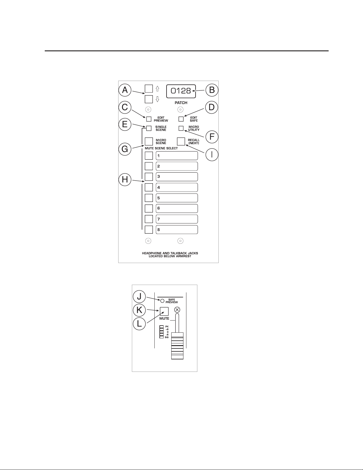
p. 98
X-VCA owner’s manual
6
microprocessor control
mute control panel
typical input or output
Page 99

p. 99
microprocessor control
6
copying a mute scene
Copying a Mute Scene:
Mute Scenes can be copied from a Sequenced Scene (Patch) to a Manual Mute
Scene. Manual Mutes cannot be copied to Sequenced Scenes or to each other.To
copy a Sequenced Scene into a Manual Mute Scene, follow the steps outlined below.
1) Press the Edit Preview button (C), it will begin to blink, indicating that the
system is in Edit Preview Mode.
2) Select Sequenced Scenes by pressing the Micro Scene (G) button; it will
illuminate.
3) Scroll to the Scene to be copied using the Up/Down (A) keys to change
the Display (B).
4) Hold down the Micro Scene button.The display will show "Cpy?".
5) Still holding down the Micro Scene button (G), now also press the
desired Manual Mute switch (H).The display will show "Copy", and the
Sequenced Scene Mute pattern is copied to the target Manual Mute, overwriting whatever pattern may have originally been there.
6) You can now select the newly created Manual Mute Scene for editing by
pressing its select switch (G).The copied Mute pattern will be there, you
can use that as a starting point for your edits.
7) Exit back to Normal mode when you’re done by pressing Edit Preview
(C) again.
NOTE:You can use this copy feature as a way to "Back-up" your Manual
Mute Scenes, even though you can’t copy from Manual Mutes to any other
Mutes. Instead, use the highest numbered Patches (120 to 127) to create
the original versions of your Manual Mute Scenes.Then use the copy function to transfer those patterns into the Manual Mutes.You can always go
back to the originals (120 to 127) and re-load (copy) them into the Manual
Mutes whenever needed.You can also use Patch 128 as an All Mute memory. Program it with all channels muted, you can then copy it to a Manual
Mute when you need to start a Scene with all channels muted instead of all
channels un-muted ( you already have a way to start a Scene with all channels un-muted, you can hold down the Edit Safe button to clear all mutes in
a Scene when editing).
Page 100

p. 100
X-VCA owner’s manual
6
microprocessor control
mute control panel
typical input or output
 Loading...