

Page 1
Owner’s Manual
SERIES
X-Monitor
Mixing Console
Page 2

p. 2
Specifications
X-Monitor owner’s manual
+0/-1dB 20Hz–20kHz ref 1kHz—any input to any output
any output <.01%
THD 20Hz–20kHz @ +15dBu out
mic ein better-than -128dBu 20Hz–20kHz—150ohm source, 60dB gain
channel mute >80dB channel routing >80dB
channel fader attenuation >90dB aux send attenuation >75dB
< +/- 30 degrees,
20Hz–20kHz—mic-in to main-out
mic-in
XLR 4k ohm balanced—max voltage gain to group balanced out= 98dB
line-in
TRS >10k ohms balanced
left/right/mono—group, aux, matrix—monitor-out
all 100 ohms balanced
headphones to drive > eight-ohms
send 50 ohms ground-compensated on
TRS jack
return >10k ohms balanced on
TRS jack
+4dBu max level
+26dBu balanced into >1k ohms
high freq +/- 15dB shelf at
12kHz
hi-mid freq +/- 15dB bell freq range 400Hz–8kHz, Q=1.5
low-mid freq +/- 15dB bell freq range
80Hz–2kHz, Q=1.5
low freq +/- 15dB bell-boost /shelf-cut freq center
80Hz, Q=.7 on boost
high-pass filter -12dB/octave freq range
20Hz–400Hz
separate on-switches for eq and high-pass filter
five-band eq on all main outputs high-pass filter:-12dB/octave freq range
20Hz–400Hz
separate on-switches for eq and high-pass filter
five-segment
LED ladder with VU-type response—displays pre-fader signal level
top red-
LED warns of impending overload anywhere within the channel
fourteen mechanical
VU-type meters with LED illumination
twelve-meters showing group-out
two dedicated solo-meters
pink-noise generator can feed the talk-back section
chassis is powder-coated
14-gauge galvanized steel with internal-bracing
modules are powder-coated
18-gauge galvanized steel with baked-epoxy screening
see dimension-drawing
five-years
frequency response
THD
noise
crosstalk
phase shift
inputs
outputs
insert
nominal output level
input channel eq
output features
channel metering
master metering
signal generator
construction
dimensions and weights
warranty
Page 3

1
3
4
master section p. 28
microprocessor control p. 48
2
group module p. 20
mono input module p. 6
Mic and line inputs
5
power supply p. 66
p. 3
Table of contents
Page 4
GROUP
p. 4
BAL OUT
XFORMER
GROUP OUT
( TO METERBRIDGE )
Ø
FADER
GRP POST
+10
GROUP
GROUP
FADER AMP
FADER
GRP PRE
(1 OF 12 SHOWN)
X-MONITOR GROUP
PEAK
SIGNAL
PRESENT
HPF
POST FDR
20 - 400HZ
GROUP PRE FDR
TB TO
GROUP
TB
FEED
-
MAIN
CABLE
50 WAY
RIBBON
SOLO
SOLO LEFT
SOLO RIGHT
& SWITCHING
POST
SOLO CONTROL
FADER
CONTROL
PRE-FADER
POST-FADER
X-MONITOR INPUT
(24 32 OR 40 FITTED)
PAD
26dB
+48V
OPTION
MUTE
MIX
1 TO 12
TO
NEXT
MODULE
LEVEL LEVELFREQ LEVEL
FREQ
LEVEL
HPF
20 - 400HZ
GAIN
15 - 70 DB
Ø
LINE
LINE
IN
BALANCED
GC
HPF
GROUP
MIX AMP
∑
MUTE
FADER AMP
EQ
ON
LFLOW MIDHI MIDHF
P
OPTION
XFORMER
SW
GROUP
INSERT SEND
EQ
ON
LF
40 TO 800
MID LO MID
200 TO 4K 100 TO 2K
LEV LEVQF LEVQF LEVF
QFF
HI MIDHF
400 TO 8K2-16K
LEV
POST
POST FDR
LOC RTN PRE
GROUP PRE FDR
& SWITCHING
SOLO CONTROL
AND
CTRL
SOLO
1 OF 4
MUTE
CIRCUITS
SAFE
PREVIEW
+10
FOUR BAND EQ
12 KHZ 400 - 8 KHZ 80 - 2 KHZ 100 HZ
HPF
INPUT
PREAMP
SW
LINE
OUT
SPLIT
BAL
INSERT RTN
GROUP
(TO EQ)
RETURN
MIX 13-16
GROUP FIVE BAND EQ
MAIN RIBBON:
SOLO
LOCAL RTN
SOLO
GROUP
TO
PREV
FROM
MODULE
CARD
MICRO
INTERFACE
INPUT CHAN
1 THRU 12
GROUP SENDS
1-4
PRE
PRE
MUTE ?
SOURCE
YES
NO
PEAK
+80-6SIG
INPUT METER
GC
PIN 1 LIFT
INSERT SEND
FADER
GRP POST
MUTE
GROUP
MUTE IF SET PRE ?
YES
NO
GROUP
ASSIGN
TO MIXES
13 THRU 16
13
& PRE CTRL
TO MIX AMPS
GROUP
FACE
CARD
MICRO
INTER-
GROUP
INPUT
MICRO
CARDS
MIX 2
MIX 1
1-2 LEV/PAN CTRL
1 - LEV
2 - PAN
AMP
PRE-SOURCE
PRE
FDR
SELECT
SOURCE
EQ
PRE
FADER
LOCAL
PRE
LOC RTN
FADER
GRP PRE
+6
14
MIX 1415MIX 1516MIX 16
MIX 13
MUTE
SAFE
PREVIEW
MIX 3
3 - LEV
FDR
EQ
POST
BAL INSERT RTN
RETURN
LEVEL
MUTE
4 - PAN
FADER
DIRECT OUT
MIX A
FROM
FEED L & R
COMMON RTN
MASTERS 1 & 2
IN
RIGHT
IN
LEFT
MUTE
LOCAL RTN
+6
RETURN
COMMON
POST
LOC RTN
SOLO
MIX 4
PRE
AND
GC
TO GROUP
STEREO
3-4 LEV/PAN CTRL
5-8
POST
SELECT
DIR OUT
MIX AMP
13-16 PRE CTRL
MUTE
LOCAL RTN
CTRL
5 - LEV
PRE
A
( FROM MASTER 2 )
SAFE
PREVIEW
MIX 5
6 - PAN
MIX 6
MIX ABMIX B
1 OF 4
CIRCUITS
5-6 LEV/PAN CTRL
COMMON RTN
7 - LEV
GAIN
GC
LEVEL
COM RTN
SHOWN
FROM
POST
MUTE
MASTER
+6
MIX AMP
TO GROUP
TO MIXES A & B
GROUP ASSIGN
WHEN SELECTED FOR STEREO PAIR OPERATION:
STEREO
SAFE
PREVIEW
CARD
MICRO
MIX 8
MIX 7
7-8 LEV/PAN CTRL
8 - PAN
OBE
FRANK
XLR
JACK
JACK
1/4” TRS
ELECT
SWITCH
FET
SWITCH
SHUNT
REMOVABLE
USER
OPTION
PANEL
SWITCH
AMP
DRIVER
BALANCED
DRIVER
GROUND COMP
LED
BICOLOR
MUTE
COMMON RTN
CORRESPONDING INPUT SEND PAIR IS RECONFIGURED
FOR LEV/PAN OPERATION (ODD IS LEV, EVEN IS PAN).
GROUP SOLO IS CHANGED FROM MONO TO STEREO:
PAIR
SW ON ODD GRP
GRP STEREO CTRL:
LEV/PAN CTRL
9 - LEV
9-12
PRE
STANDARD OUTPUT LEVEL IS +4 dBu AT 0 VU
P
FADER
100MM
POT PAD LED
ROTARY
ALL SWITCHES SHOWN IN THE UP (DESELECTED) POSITION
BAL OUT
Ø
FADER
A - POST
+10
MIX A
LEVEL
FADER
A - PRE
-
SELECT
TO EQ 1
5-BAND EQ
MTX 1 OR MIX A
SWITCH BETWEEN
X-MONITOR MASTER MODULE (UPPER AREA)
MIX A
INST RTN
ODD GRP SOLOS TO LEFT, EVEN GRP TO RIGHT.
MIX A
INSERT
SEND RTN
GC
LED ON EVEN GRP
A
MIX AMP
∑
9-10 LEV/PAN CTRL
11 - LEV
TALKBACK
TB
MIX A
FEED
MIX 13
MIX 12
MIX 11
11-12 LEV/PAN CTRL
MIX 13
12 - PAN
(TO INPUTS)
MIX 9
10 - PAN
MIX 10
LEGENDS
PIN 2 HOT ON ALL BALANCED OUTPUTS (XLR JACKS)
FOR UNBALANCED OPERATION:
TIE PIN 3 TO PIN 1, USE PIN 2 FOR OUTPUT, PIN 1 FOR GND
“Ø” SYMBOL INDICATES POLARITY REVERSE
UNDERLINED
1 2 3 4 5 6 7 8 9 10 11 12 SOLO L SOLO R
AMP(LIFIER) GAIN SHOWN IN DB WHEN NEEDED
WHEN SHOWN: 1/4” TRS SWITCHING JACKS HAVE NORMALLY CLOSED CONTACTS
USER OPTIONS IMPLEMENTED WITH REMOVABLE SHUNTS
DEFAULT SHUNT POSITION SHOWN
MIX B
BAL OUT
OPTION
XFORMER
SOLO
MUTE
Ø
FADER
B - POST
+10
MIX A
MUTE
MIX B
LEVEL
(MICRO CONTROLLED)
MUTE AND SOLO SWITCHING
FADER
B - PRE
&
MICRO
TO SOLO
-
SELECT
TO EQ 2
PK
5-BAND EQ
SIG
MTX 2 OR MIX B
SWITCH BETWEEN
MIX B
INST RTN
PRE-FADER
POST-FADER
MIX B
INSERT
SEND RTN
GC
B
MIX AMP
∑
TALKBACK
MIX A - LOCATED ON MASTER 1
MIX B
MIX 14
MIX 16
MIX 15
13-16 PRE CTRL
(FROM MASTER MOD)
MIX A
MIX 15
MIX 16
MIX 14
ASSIGNS
13 THRU 16
LAMP DIM
( ON REAR )
12 METERS FOR GROUP OUT , 2 FOR SOLO LEFT & RIGHT
POWER INLET
STANDARD IEC
METERBRIDGE - 14 MECHANICAL VU METERS WITH LED ILLUMINATION
FOR COOLING
LOW-NOISE FAN
GROUND
ISOLATING CONSOLE
REMOVABLE LINK FOR
LINKING BACK-UP SUPPLY
DUAL DC CONNECTORS FOR
OPTION
XFORMER
MUTE
MIX B
MUTE
TO SOLO
PK
PRE-FADER
POST-FADER
TB
FEED
MIX B
MIX A
MIX B
A & B
ASSIGNS
IN • MIDI • OUT
12V LAMP SOCKETS - 2 OR 4
DC INPUT ( ON REAR )
50/60 HZ
90-250VAC
BAL OUT
MATRIX 1 (2)
SOLO
FADER
MTX - POST
+10
LEVEL
MATRIX
MATRIX
(MICRO CONTROLLED)
PRE-FADER
MUTE AND SOLO SWITCHING
—
&
TO EQ 1 (2)
5-BAND EQ
MICRO
CAN SELECT EQ
TO BE ON EITHER
SIG
MATRIX
INST RTN
INSERT
MATRIX
SEND RTN
GC
∑
MIX AMP
MATRIX 1 (2)
MIX B - LOCATED ON MASTER 2
OUT 13
OUT 14
(FROM MASTER 2)
MATRIX TALKBACK
SOLO LEFT
SOLO RIGHT
∑
∑
MIX
SOLO
AMPS
L SOLO R
SOLO
AUDIO
TO METER BRIDGE
EXT MONITOR IN
ALTERNATE OUT
M4
( ON REAR PANEL )
EXTERNAL TALKBACK
M2 M3
X-MONITOR MASTER MODULE (LOWER AREA)
( ON REAR OF METER BRIDGE )
MONITOR OUT
+/- 18V, +12V, +48V
COMMON RETURN
MODEL 5A
CREST X-SERIES POWER SUPPLY ( REAR VIEW )
M1
MUTE
MUTE
MATRIX
(MICRO CONTROLLED)
MUTE AND SOLO SWITCHING
INTO THE MIX A AND B
MATRIX 1 (2) -DEFAULT
PATHS INSTEAD OF THE
OR MIX A (B)-SWITCHED
THAT CAN BE SWITCHED
MATRIX 1 AND 2 HAVE EQS
EXT IN
MATRIX
EXT IN
OUT 15
OUT 16
MIX
INPUT
OUTPUT
- ACTIVE -
SOLO CONTROL & STATUS
LEFT RIGHT
LEFT RIGHT
OUT IN
LEFT RIGHT
LEFT RIGHT
SOLO
TO SOLO BUS & MICRO INTERFACE
DEFAULT MATRIX PATH
MIX 13 (14)
∑
13 (14)
GC
GC
MIX AMP
MATRIX 1 (2) - LOCATED ON MASTER 1 (2)
TO MATRIX MIXES
OUT
13 (14)
SOLO
INPUT
ACTIVE
CLEAR
ALT
LEVEL
TB
ON
ON
PK
SIG
TB
BAL OUT
MATRIX 3 (4)
MATRIX
POST-FADER
+10
LEVEL
MATRIX
MATRIX
PRE-FADER
—
TO EQ 3 (4)
5-BAND EQ
MATRIX
INST RTN
INSERT
MATRIX
SEND RTN
GC
∑
MIX AMP
MATRIX 3 (4)
( MATRIX 1 SHOWN, MATRIX 2 IS IDENTICAL )
OUT 13
(FROM MASTER 2)
MATRIX TALKBACK
LAST
POST
FADER
PRIORITY
PRESSED
A-B
TO ALT
ON
EXT TB
( B )
LEVEL
TB
OUT
MONITOR
LEFT & RIGHT
TO ALL GROUPS
COMMON RETURN
COM RTN - R
MASTER LEV
+10
+10
COM RTN - L
MASTER LEV
Ø
SAFE
PREV
MUTE
ALWAYS ON
OUT 14
MIX A
LEVEL
MATRIX PATH
- PRE -
MUTE
MATRIX
OUT 15
128
MIX B
TB AUDIO
SOLO
SOLO CONTROL
COMMON RETURN
SOLO
SOLO
MUTE
(MICRO CONTROLLED)
MUTE AND SOLO SWITCHING
TO SOLO BUS & MICRO INTERFACE
INTO MIXES A AND B
EQS, AND THE MATRIX
OUTPUTS CAN BE ADDED
MATRIX 3 & 4 HAVE DEDICATED
EXT IN
MATRIX
EXT IN
MIX AMP
MIX 15 (16)
∑
OUT 16
MIX
OUT
15 (16)
15 (16)
-
TO
SIDE
LEFT
MICRO
CARDS
GROUP
EDIT
SAFE
MICRO
UTILITY
SCENE
SEQUENCED
EDIT
SCENE
SINGLE
PREVIEW
SEQUENCE
LEFT
SOLO
AUDIO
SOLO
RIGHT
AUDIO
LATCH
TAP TO
(TO RIBBON)
TALK ON
TB
SUM
MONO
MUTE
MONITOR
AUTO
SOLO
COM R
MUTE
MIX L&R
TO SOLO
CTRL
FROM
POST-FADER
COM L
SOLO
AB
MIX A & B
MATRIX
TO A (B)
MATRIX 3 (4)
MIX A AND B
TO BE ADDED INTO
ALLOWS MATRIX 3 AND 4
TO MIX A (B)
TO MATRIX MIXES
MASTER
GO
SCENE ON
IN
EXT
MON
-
HOLD FOR
MOMENTARY
TB
LOGIC
SWITCH
MASTER 1
LOCATED ON
CONTROLS
MATRIX
PRE-FADER
POST-FADER
MATRIX 3 (4) - LOCATED ON MASTER 3 (4)
( MATRIX 3 SHOWN, MATRIX 4 IS IDENTICAL )
-
FACE
CARD
MICRO
INTER-
GROUP
INPUT &
312
L
ANU
A
M
HP
LEVEL
OFF / ON
+48 VOLT
TALK BACK
+48V
TB
( A )
LEVEL
SOLO
AUDIO
LEFT RIGHT
CTRL
SOLO
FOR DETAILS >
SEE BLOCK DIAG
EQ TO
MIX A (B)
PRE-FADER
TO MATRIX 3 (4)
EQ
( 1 OF 4 SHOWN )
5-BAND EQ - NORMALLY ON MATRIX PATH
INSERT RETURN
FROM MATRIX 3 (4)
TO
CONTROL
T
E
U
M
LOCATED UNDER ARMREST
PINK
NOISE
TB AUDIO
MATRIX
TALK TO
PRE-FADER
TO MATRIX 1 (2)
ON
LEV
FR
LEV
FR
LEV
FR
LEV
FR
LEV
AVAILABLE ON EQ 1 & 2
PATH SWITCHING BETWEEN
MATRIX AND MAIN MIX ONLY
-
SIDE
INPUT
RIGHT
MICRO
CARDS
645
7
SCENE
S
HEADPHONE
TALK BACK
PINK
NOISE
1 TRU 4
TO MATRIX
13-16
PRE-FADE
AUDIO
TALKBACK
PRE-FADER
TO MIX A (B)
AVAILABLE ON EQ 1 & 2
PATH SWITCHING BETWEEN
MATRIX AND MAIN MIX ONLY
LF
20 TO 400
LO MID
MIDHI MIDHF
FIVE BAND EQ (1 OF 4)
400 TO 8K 200 TO 4K 100 TO 2K12K
FROM MIX A (B)
INSERT RETURN
INSERT RETURN
FROM MATRIX 1 (2)
8
MICRO MUTE CONTROL
OUT
IN
GEN
13 THRU 16
CHANGES MIXES
TO PRE-FADER INSTEAD
OF DEFAULT POST-FADER
TO INPUTS
AND GROUPS
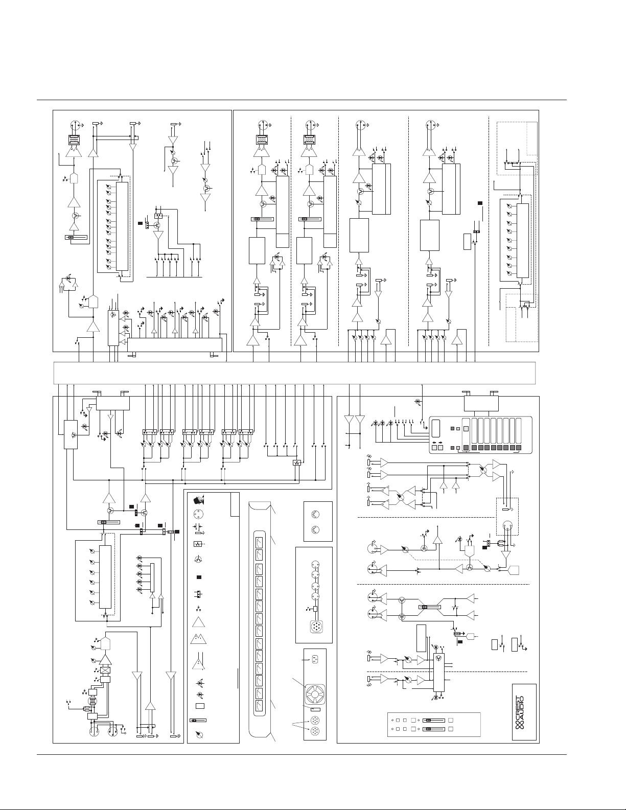
X-Monitor Block Diagram
X-MONITOR BLK DIA-REV1.2-7/27/01
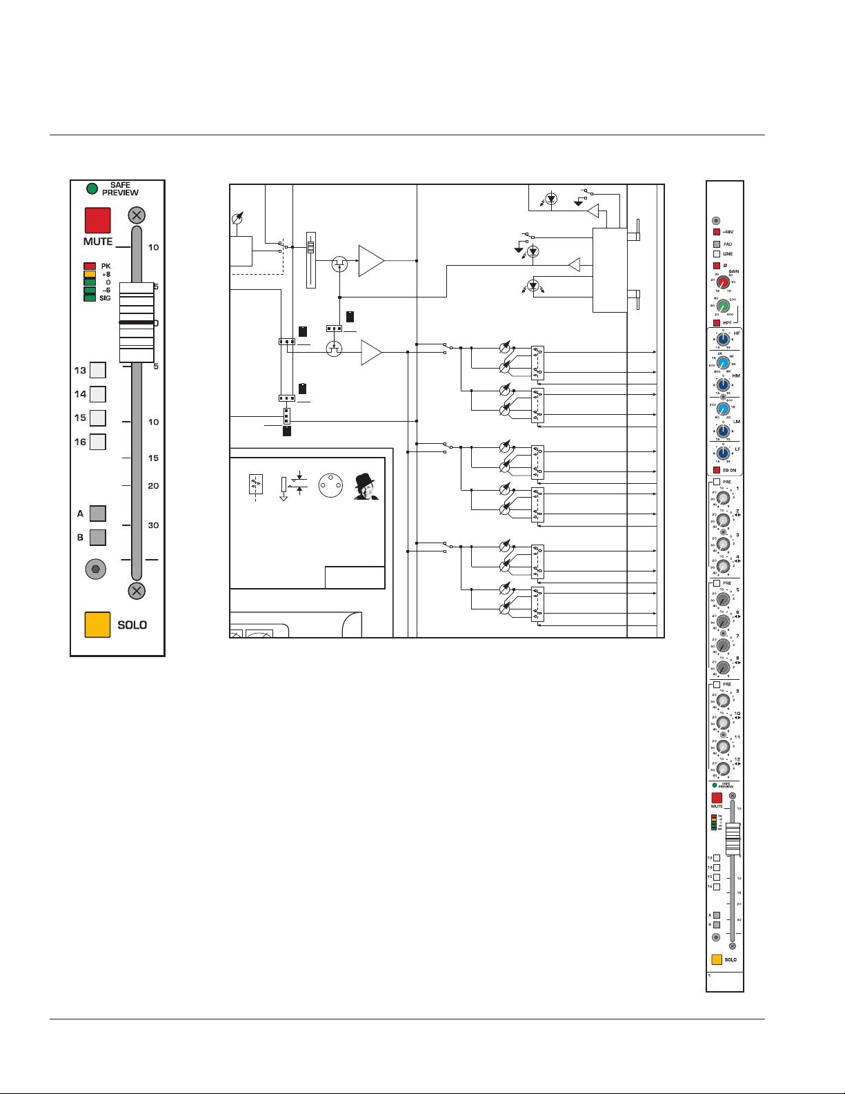
Page 5
Format
This manual uses a format that is intended to be easy to read, yet technical for those who need to
know all the details. For feature descriptions, this is done by devoting the left side of each page to 1)
an overall module picture, 2) a block diagram, and 3) a control closeup. These images all pertain to the
features and control descriptions on the right side of the page. Also, for certain features like the microprocessor system and the solo system that appear over and over again, references are made to sections devoted to these features.
The intention is to make the manual easy to read while including all the technical details needed for
getting the most out of the X-Monitor console, a flexible and feature-rich addition to Crest Audio's growing line of audio mixing console products.
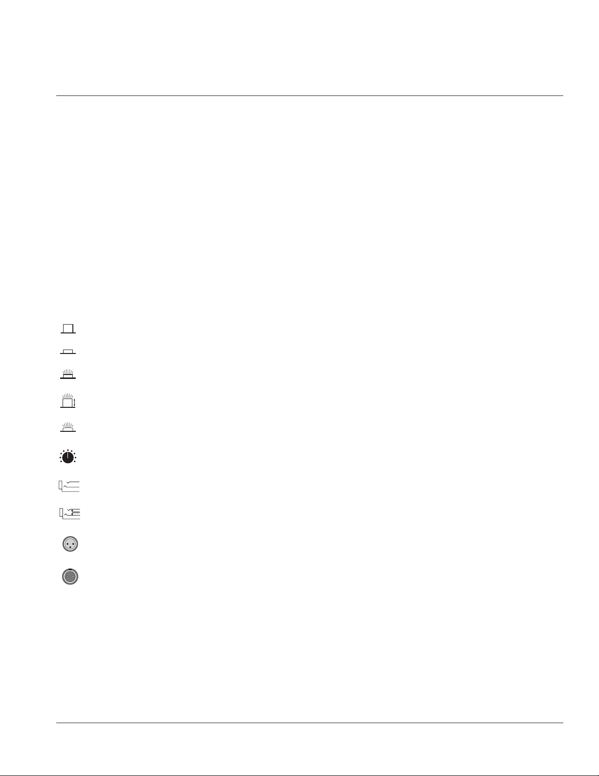
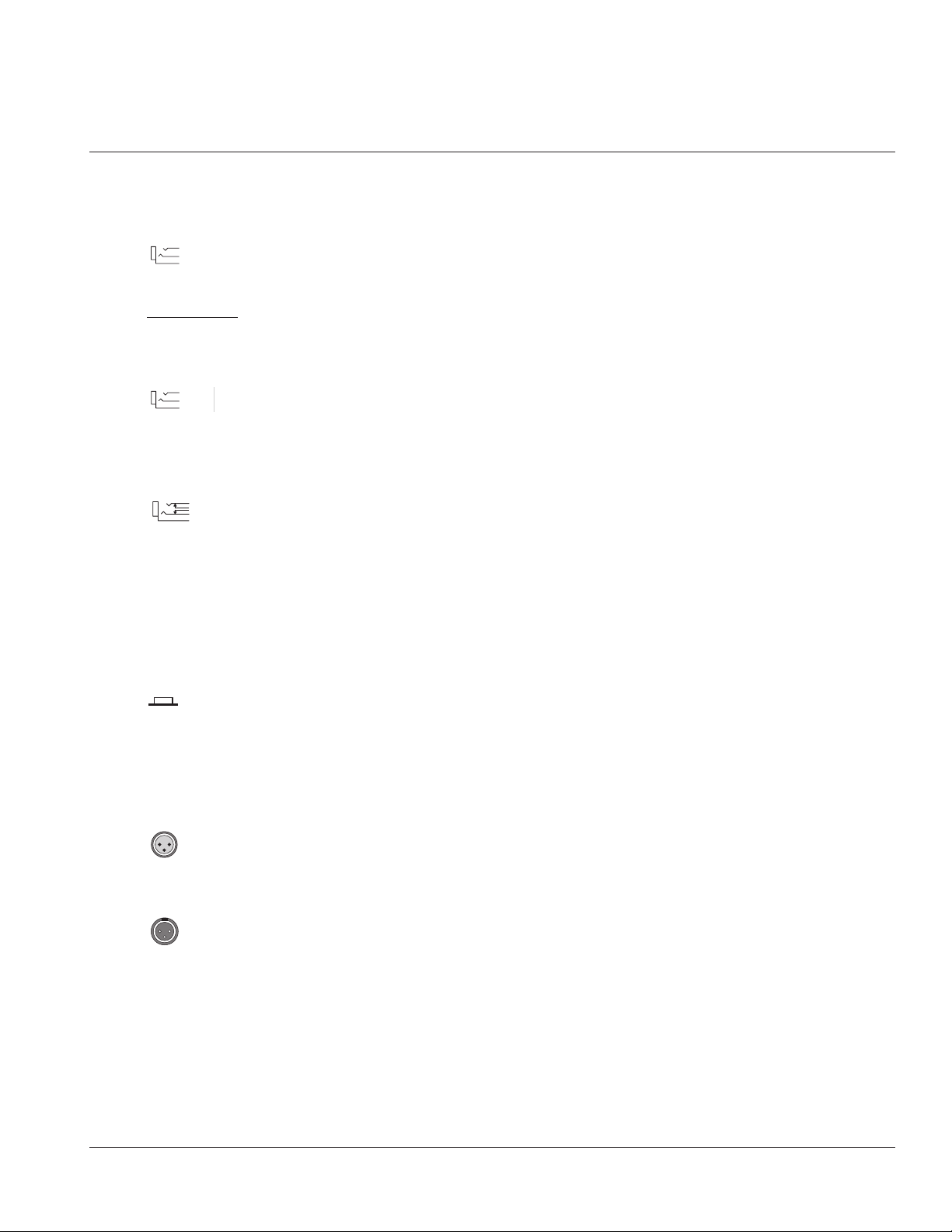
Conventions
Control Icons
This manual uses little pictures, or icons to illustrate what the control descriptions are referring to. This
makes it possible to avoid redundant wording and makes the control descriptions clear.
Switch in the UP, non-activated position
Switch in DOWN, activated position
Switch that illuminates when in the DOWN position
Momentary switch that illuminates when activated
Illuminated LED, indicating that its associated feature is activated
Potentiometer
Standard 1/4" TRS jack (used for line level inputs and insert sends)
1/4" TRS jack with normal switching (used on insert returns)
Female XLR input jack
Male XLR output jack
p. 5
How to use this manual
LED
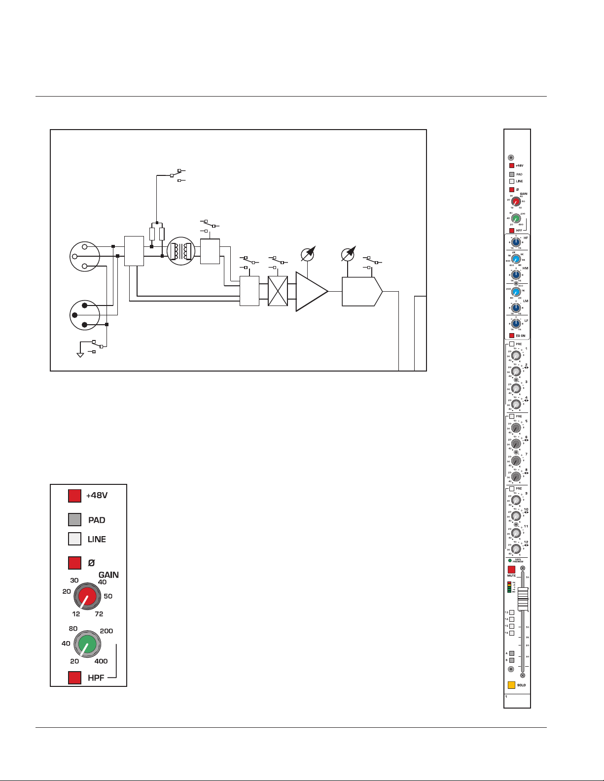
Page 6

Input
Module
Controls
Block diagram
p. 6
1
Mono input module
X-Monitor owner’s manual
BALANCED
IN
SPLIT
OUT
PIN 1 LIFT
LINE
SW
+48V
XFORMER
OPTION
26dB
PAD
P
LINE
LINE
SW
Ø
GAIN
15 - 70 DB
INPUT
PREAMP
HPF
20 - 400HZ
HPF
Page 7

Features
Phantom power +48V
48 volts DC is applied to pins 2 and 3 on the mic-input XLR connector. This option
is used with condenser microphones and active direct boxes that require an external DC
voltage (phantom power) in order to operate.
Pad
The mic-input signal is attenuated by 28dB to prevent some signals (e.g. kick drum or
lead vocal) from overloading the preamp stage.The pad is used to bring a hot mic-input signal down to a controllable level.The pad is not functional when the LINE switch is depressed.
Line
The input preamp circuit is set up to accept a mic-level signal. This signal is brought in
via the XLR mic-input connector located on the rear panel.The 1/4" TRS input jack is disabled.
The input preamp circuit is set up to accept a line-level signal from either the XLR
mic-input connector or the 1/4" TRS input jack, both located on the rear panel.When a plug
is inserted into the 1/4" TRS input jack, the XLR mic-input connector is disabled.
Polarity reverse—ø
This feature is used for correcting or minimizing polarity and phase related errors. For
example, occasionally a balanced input connection is reverse-wired before it gets to the
mixing console. This can happen in microphones, or in snake line interfaces. By using the
polarity reverse feature, this type of error can be corrected.
Normal polarity
Polarity inverted
If the 48V phantom
power switch is
engaged, depressing this
Line switch disconnects
phantom power from the
mic input XLR.
+
When similar signals
from different channels are combined, phase
cancellations can occur.
Reversing the polarity of an
input signal often corrects
such phasing errors.
+
The 48V switch should
not be engaged when
using standard (dynamic)
microphones, or other
sources that do not use
phantom power.
a
p. 7
Mono input module
1
Page 8
Input
Module
Controls
Block diagram
p. 8
1
Mono input module
X-Monitor owner’s manual
BALANCED
IN
SPLIT
OUT
PIN 1 LIFT
LINE
SW
+48V
XFORMER
OPTION
26dB
PAD
P
LINE
LINE
SW
Ø
GAIN
15 - 70 DB
INPUT
PREAMP
HPF
20 - 400HZ
HPF
Page 9
Features
Gain
The Input gain control range is closely related to the status of the PAD switch and the LINE
switch. In order to establish proper gain structure in the console, input gain settings must
be set correctly.
LINE—switch-up PA D —switch-up
12 to 72dB of gain can be added the mic-input signal.
The impedance at the input XLR is 4kΩ.
LINE—switch-up PA D —switch-down
-16 to 44dB of gain can be added to the mic-input signal.
The impedance at the input XLR is 4kΩ.
LINE—switch-down PA D —switch-up or -down
-10 to 45dB of gain can be added the line-input signal.
The impedance at the input XLR and input 1/4" TRS is 20kΩ.
High-pass filter—HPF
Proper use of the high-pass filter reduces or eliminates unwanted low frequencies without
substantially affecting the program material.Quite often such unwanted low frequencies are
included with in-coming mic- or line-input signals. For example, stage rumble or wind can
be picked up through vocal mics.The slope of the high-pass filter is -12dB per octave.
HPF
High-pass filter is on.
HPF—variable control
When the high-pass filter is on, this control selects a frequency between 20Hz and
400Hz as the point where attenuation begins.
If the channel peak
LED is illuminated,
first try lowering
the input gain control.
Only when this method is
unsuccessful should the pad
switch be engaged.
+
p. 9
Mono input module
1
Page 10
Input
Module
Controls
Block diagram
E
R
E
p. 10
1
Mono input module
X-Monitor owner’s manual
GAIN
- 70 DB
PUT
EAMP
HPF
20 - 400HZ
HPF
PRE
FADER
X-MONITOR INPUT
(24 32 OR 40 FITTED)
FREQ LEVEL LEVELFREQ LEVEL
LEVEL
12 KHZ 400 - 8 KHZ 80 - 2 KHZ 100 HZ
FOUR BAND EQ
INPUT METER
+80-6SIG
LFLOW MIDHI MIDHF
PEAK
EQ
EQ
ON
FDR
PRE
SOURCE
SELECT
FADER AMP
NO
PRE-SOURCE
YES
AMP
+10
SOU
MUT
PR
Page 11

Input EQ features
Many audio signals coming into the console require some degree of corrective eq in order
to be part of a good sounding mix.The X-Monitor Input EQ allows the user to tailor the
incoming sound.
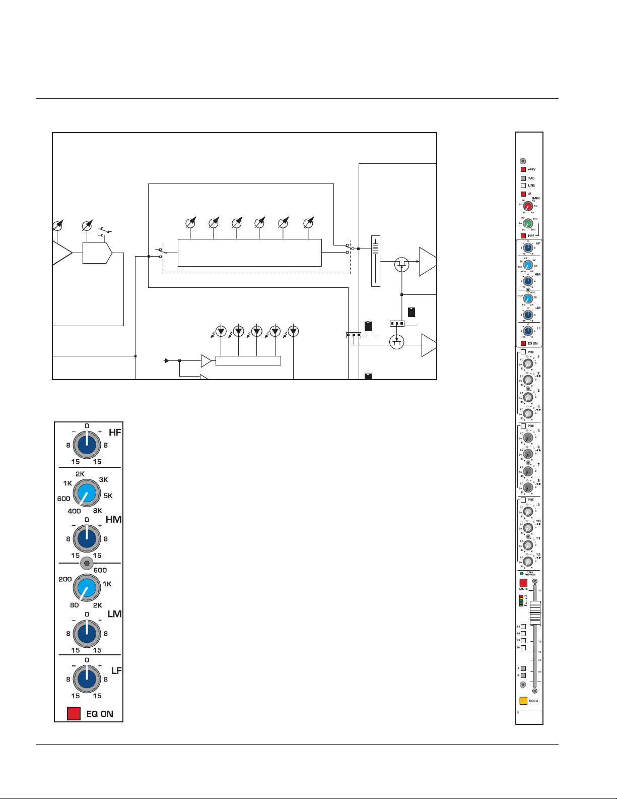
The input EQ consists of four bands:high, high-mid,low-mid, and low. The high band is shelving, the low band offers shelving cut with a bell boost. The two mid-bands are bell shaped
with a Q of 2 and a generous overlap of adjacent operating frequencies. An independent,
variable high pass filter provides additional problem-solving flexibility.
High frequency—HF
Boost / Cut
15dB boost and cut at 12 kHz. Shelving eq.
High mid—HM
Boost / Cut
15dB boost and cut with a Q of 2.
Frequency Continuously sweepable between 400 Hz and 8 kHz.
Low mid—LM
Boost / Cut
15dB boost and cut with a Q of 2.
Frequency Continuously sweepable between 100 Hz and 2 kHz.
Low frequency—LF
Boost / Cut
15dB boost and cut at 100 Hz. Bell boost / Shelving cut.
Eq on
Equalizer is on. This switch is used to activate the EQ section and can be used to make
A/B comparisons between "flat" and eq'd signals.
p. 11
Mono input module
1
Page 12
Input
Module
Controls Block diagram
SOLO
p. 12
1
Mono input module
X-Monitor owner’s manual
EVEL
EQ
ELECT
SWITCH
EQ
EQ
PRE
POST
ON
1/4” TRS
JACK
LF
00 HZ
DIR OUT
SELECT
0 VU
(XLR JACKS)
UT, PIN 1 FOR GND
RSE
FDR
PRE
SOURCE
SELECT
FDR
FADER AMP
NO
PRE-SOURCE
XLR
JACK
LEGENDS
YES
AMP
+10
PRE
SOURCE
MUTE ?
OBE
FRANK
1-4
PRE
5-8
PRE
9-12
PRE
MUTE
SAFE
PREVIEW
GROUP SENDS
1 THRU 12
1 - LEV
2 - PAN
3 - LEV
4 - PAN
5 - LEV
6 - PAN
7 - LEV
8 - PAN
9 - LEV
10 - PAN
11 - LEV
12 - PAN
MUTE
AND
SOLO
CTRL
1 OF 4
CIRCUITS
INPUT CHAN
MICRO
INTERFACE
CARD
MIX 1
MIX 2
1-2 LEV/PAN CTRL
MIX 3
MIX 4
3-4 LEV/PAN CTRL
MIX 5
MIX 6
5-6 LEV/PAN CTRL
MIX 7
MIX 8
7-8 LEV/PAN CTRL
MIX 9
MIX 10
9-10 LEV/PAN CTRL
MIX 11
MIX 12
11-12 LEV/PAN CTRL
TO
NEXT
MODULE
FROM
PREV
MODULE
Page 13
Mix send features
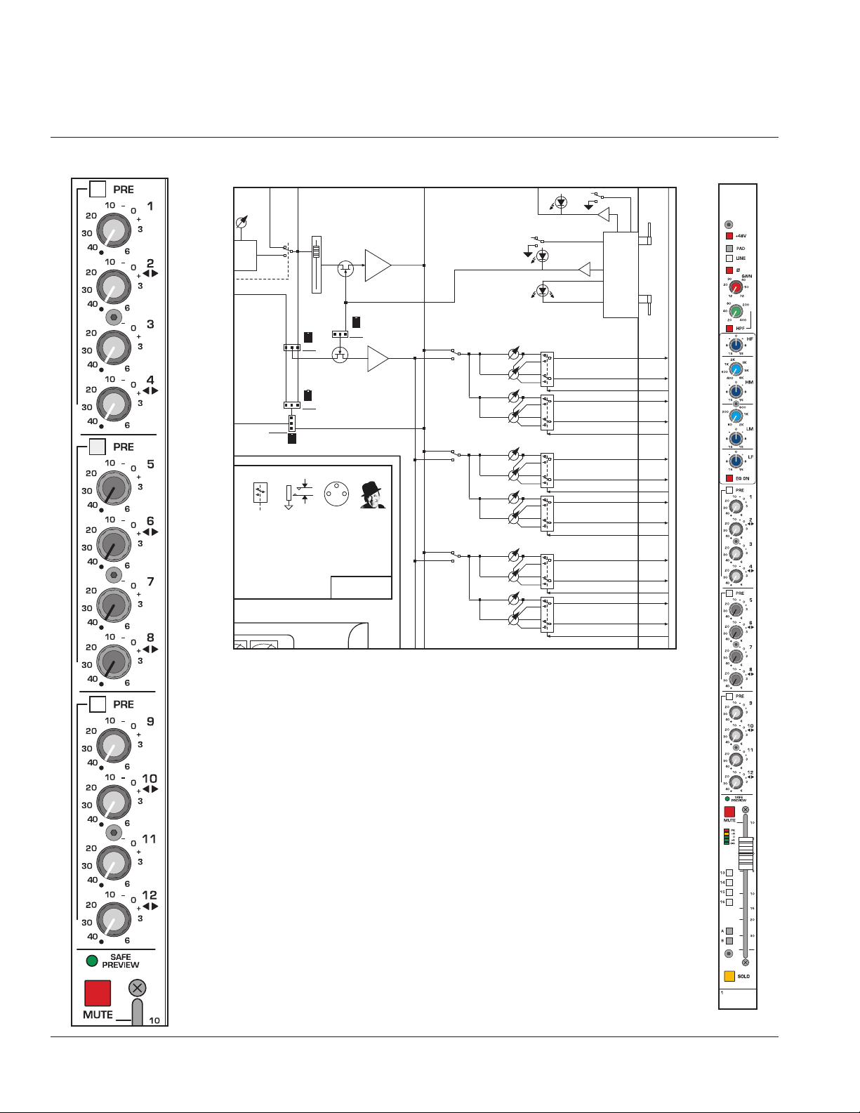
The X-Monitor input strip has twelve Mix sends. Pre/Post fader switching is done in three
groups of four, 1 through 4, 5 through 8, and 9 through 12.These Mix sends are routed to
their corresponding outputs for creating up to twelve individual mono monitor mixes.They
can also be configured as stereo pairs,creating up to six stereo mixes.When configured for
stereo operation, the odd numbered pot becomes the stereo level control and the even
numbered pot becomes the pan control.Stereo configuration is done in stereo pairs (1&2,
3&4, 5&6...) and is selected in the Group output section (see Group output section for
more information.
Mix Sends 1-4, 5-8, 9-12
These knobs adjust the amount of signal sent to the twelve outputs.Unity gain occurs
at the the zero (1 - 2 o’clock) setting.
In mono mode, each control independently determines the send level for the respective
mix. When stereo mode is selected, the top (odd numbered) control sets signal level while
the bottom (even numbered) control pans the signal between odd and even group buses
(odd = left, even = right).
Mix PRE switches 1-4, 5-8, 9-12
The PRE switches determine the source for the three groups of four MIX sends.The signal that these switches use for the PRE setting can be further defined by changing the position of a couple of internal jumpers. See
INTERNAL JUMPER OPTIONS.
MIX SENDS are post-insert, post-eq, post-mute, post-fader
MIX SENDS are post-insert, post-eq, post-mute, pre-fader
Safe preview
Safe Preview LED
See LOCAL MICROPROCESSOR CONTROL section
Mute
Mute switch
See LOCAL MICROPROCESSOR CONTROL section
With a FOH Console,
it's typical to make
Aux sends Post-fader
for driving effects, and Prefader when used for monitors. With a Stage Monitor
Console such as the XMonitor, all Mix Sends are
normally set for Post-Fader;
the Engineer uses the
Channel fader to control the
level to all mixes.
+
p. 13
Mono input module
1
LED
Page 14
Input
Module
Controls Block diagram
SOLO
p. 14
1
Mono input module
X-Monitor owner’s manual
EVEL
EQ
ELECT
SWITCH
EQ
EQ
PRE
POST
ON
1/4” TRS
JACK
LF
00 HZ
DIR OUT
SELECT
0 VU
(XLR JACKS)
UT, PIN 1 FOR GND
RSE
FDR
PRE
SOURCE
SELECT
FDR
FADER AMP
NO
PRE-SOURCE
XLR
JACK
LEGENDS
YES
AMP
+10
PRE
SOURCE
MUTE ?
OBE
FRANK
1-4
PRE
5-8
PRE
9-12
PRE
MUTE
SAFE
PREVIEW
GROUP SENDS
1 THRU 12
1 - LEV
2 - PAN
3 - LEV
4 - PAN
5 - LEV
6 - PAN
7 - LEV
8 - PAN
9 - LEV
10 - PAN
11 - LEV
12 - PAN
MUTE
AND
SOLO
CTRL
1 OF 4
CIRCUITS
INPUT CHAN
MICRO
INTERFACE
CARD
MIX 1
MIX 2
1-2 LEV/PAN CTRL
MIX 3
MIX 4
3-4 LEV/PAN CTRL
MIX 5
MIX 6
5-6 LEV/PAN CTRL
MIX 7
MIX 8
7-8 LEV/PAN CTRL
MIX 9
MIX 10
9-10 LEV/PAN CTRL
MIX 11
MIX 12
11-12 LEV/PAN CTRL
TO
NEXT
MODULE
FROM
PREV
MODULE
Page 15

Level meter features
Level meter
Each input includes a five-segment LED meter for visually moni-
toring signal levels.This is essential for setting up and maintaining proper gain structure.
Peak indicator—PK
The input signal is monitored at several points throughout the channel.These points
are the mic preamp, the EQ stage and the fader stage. Overload at any of these stages will
cause the red peak-LED to light.
The channel gain should reduced if this occurs.
Signal level LEDs
These three LEDs light up at +8—yellow,0—green,and -6 dB—green.This level range
-6 to +8 is the optimum operating range. Compressed or relatively constant signals should
remain close to 0.
Signal present indicator—SIG
This green-LED varies in brightness in response to signal levels between -40 dB and 6 dB.
p. 15
Mono input module
1
LEDLEDLEDLEDLED
LED
LED
LED
Page 16

Input
Module
Controls Block diagram
SOLO
p. 16
1
Mono input module
X-Monitor owner’s manual
EVEL
EQ
ELECT
SWITCH
EQ
EQ
PRE
POST
ON
1/4” TRS
JACK
LF
00 HZ
DIR OUT
SELECT
0 VU
(XLR JACKS)
UT, PIN 1 FOR GND
RSE
FDR
PRE
SOURCE
SELECT
FDR
FADER AMP
NO
PRE-SOURCE
XLR
JACK
LEGENDS
YES
AMP
+10
PRE
SOURCE
MUTE ?
OBE
FRANK
1-4
PRE
5-8
PRE
9-12
PRE
MUTE
SAFE
PREVIEW
GROUP SENDS
1 THRU 12
1 - LEV
2 - PAN
3 - LEV
4 - PAN
5 - LEV
6 - PAN
7 - LEV
8 - PAN
9 - LEV
10 - PAN
11 - LEV
12 - PAN
MUTE
AND
SOLO
CTRL
1 OF 4
CIRCUITS
INPUT CHAN
MICRO
INTERFACE
CARD
MIX 1
MIX 2
1-2 LEV/PAN CTRL
MIX 3
MIX 4
3-4 LEV/PAN CTRL
MIX 5
MIX 6
5-6 LEV/PAN CTRL
MIX 7
MIX 8
7-8 LEV/PAN CTRL
MIX 9
MIX 10
9-10 LEV/PAN CTRL
MIX 11
MIX 12
11-12 LEV/PAN CTRL
TO
NEXT
MODULE
FROM
PREV
MODULE
Page 17

Bus assignment features
In addition to providing full variable send capabilities in the Mix section,the X-Monitor also
offers audio grouping facilities for sending input signals to the output matrix section, and
directly to the A and B output masters for creating additional mixes. All assignments are
normally derived Post-fader(post-eq and post-mute).
Bus assignments 13, 14, 15 & 16
The input signal is assigned to Buses 13 thru 16 which feed Matrix 1 - 4, located above
the master control section.The feed to Buses 13-16 is normally Post-fader. All Bus 13-16
sends (from Inputs and Groups) can be globally switched to Pre-fader by using the 13-16
PRE switch, located in the Master section.
A Bus assignment
The Input signal is assigned to the main A output bus.This feed is always Post-fader.
B Bus assignment
The Input signal is assigned to the main B output bus.This feed is always Post-fader.
Input fader
The 100mm channel fader is the primary level control for all Post-fader signals being sent
to any of the console’s mix buses.The fader offers greater than 90dB of attenuation and up
to 10dB of boost . Normal operation is between -10 and 0.
Solo switch
Pressing this momentary switch will include (illuminate) or exclude (not-illuminated)
the channel from the consoles solo system. See Master Control Section for information on
Solo options.
p. 17
Mono input module
1
Page 18
Input
Module
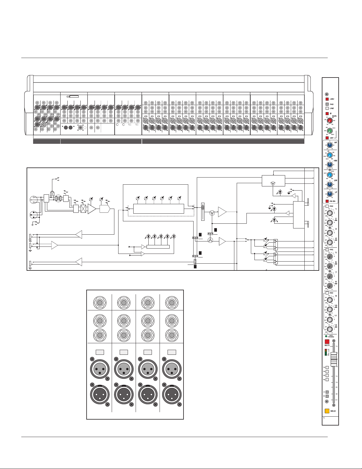
X-Monitor rear-view (28 channel, 40 position frame shown)
master groups
X-Monitor
mono inputs
R
t
n
Pin 1 Lift
X–Monitor Input
Insert
Dir Out
Split Out
Bal Input
S
e
n
d
C
R
t
n
Pin 1 Lift
Insert
Dir Out
Split Out
Bal Input
S
e
n
d
R
t
n
Pin 1 Lift
Insert
Dir Out
Split Out
Bal Input
S
e
n
d
R
t
n
Pin 1 Lift
Insert
Dir Out
Split Out
Bal Input
S
e
n
d
R
t
n
Pin 1 Lift
X–Monitor Input
Insert
Dir Out
Split Out
Bal Input
S
e
n
d
C
R
t
n
Pin 1 Lift
Insert
Dir Out
Split Out
Bal Input
S
e
n
d
R
t
n
Pin 1 Lift
Insert
Dir Out
Split Out
Bal Input
S
e
n
d
R
t
n
Pin 1 Lift
Insert
Dir Out
Split Out
Bal Input
S
e
n
d
R
t
n
Pin 1 Lift
X–Monitor Input
Insert
Dir Out
Split Out
Bal Input
S
e
n
d
C
R
t
n
Pin 1 Lift
Insert
Dir Out
Split Out
Bal Input
S
e
n
d
R
t
n
Pin 1 Lift
Insert
Dir Out
Split Out
Bal Input
S
e
n
d
R
t
n
Pin 1 Lift
Insert
Dir Out
Split Out
Bal Input
S
e
n
d
R
t
n
Pin 1 Lift
X–Monitor Input
Insert
Dir Out
Split Out
Bal Input
S
e
n
d
C
R
t
n
Pin 1 Lift
Insert
Dir Out
Split Out
Bal Input
S
e
n
d
R
t
n
Pin 1 Lift
Insert
Dir Out
Split Out
Bal Input
S
e
n
d
R
t
n
Pin 1 Lift
Insert
Dir Out
Split Out
Bal Input
S
e
n
d
R
t
n
Pin 1 Lift
X–Monitor Input
Insert
Dir Out
Split Out
Bal Input
S
e
n
d
C
R
t
n
Pin 1 Lift
Insert
Dir Out
Split Out
Bal Input
S
e
n
d
R
t
n
Pin 1 Lift
Insert
Dir Out
Split Out
Bal Input
S
e
n
d
R
t
n
Pin 1 Lift
Insert
Dir Out
Split Out
Bal Input
S
e
n
d
R
t
n
Pin 1 Lift
X–Monitor Input
Insert
Dir Out
Split Out
Bal Input
S
e
n
d
C
R
t
n
Pin 1 Lift
Insert
Dir Out
Split Out
Bal Input
S
e
n
d
R
t
n
Pin 1 Lift
Insert
Dir Out
Split Out
Bal Input
S
e
n
d
R
t
n
Pin 1 Lift
Insert
Dir Out
Split Out
Bal Input
S
e
n
d
X–Monitor Group 1–4
S
e
n
d
R
t
n
I
n
s
e
r
t
Local Rtn 4
T= OUT
+
R= G COMP
S= GND
T= IN
+
R= IN
–
S= GND
1
2
3
1= GND
2= OUT
+
3= OUT
–
2
1
3
1= GND
2= IN
+
3= IN
–
XLR Female XLR Male 1/4” Output 1/4” Input
Ext Input
Local Rtn
Insert Rtn
Common Rtn
Alt Output
Insert Send
Split Out
Main Out
Group Out
Matrix Out
Monitor Out
Talkback Out
Mic In
Talkback In
4
Group Out
C
S
e
n
d
R
t
n
I
n
s
e
r
t
Local Rtn 3
3
Group Out
S
e
n
d
R
t
n
I
n
s
e
r
t
Local Rtn 2
2
Group Out
S
e
n
d
R
t
n
I
n
s
e
r
t
Local Rtn 1
1
Group Out
4321
X–Monitor Group 5–8
Common
Return R
C
Common
Return L
S
e
n
d
R
t
n
I
n
s
e
r
t
Local Rtn 8
8
Group Out
S
e
n
d
R
t
n
I
n
s
e
r
t
Local Rtn 7
7
Group Out
S
e
n
d
R
t
n
I
n
s
e
r
t
Local Rtn 6
6
Group Out
S
e
n
d
R
t
n
I
n
s
e
r
t
Local Rtn 5
5
Group Out
8765
In • MIDI • Out
To Meter Bridge
Lamp
Dim
DC IN
X–Monitor Group 9–12
1= +12V
2= +18V
3= AGND
4= AGND
5= DGND
6= +48V
7= –18V
12
345
67
C
S
e
n
d
R
t
n
I
n
s
e
r
t
Local Rtn 12
12
Group Out
S
e
n
d
R
t
n
I
n
s
e
r
t
Local Rtn 11
11
Group Out
S
e
n
d
R
t
n
I
n
s
e
r
t
Local Rtn 10
10
Group Out
S
e
n
d
R
t
n
I
n
s
e
r
t
Local Rtn 9
9
Group Out
12 11 10 9
Insert
Send
Matrix 4
X–Monitor Master
Insert
Return
Ext
In
Out
Monitor
Out
L
Monitor
Out
R
Insert
Send
Insert
Return
Main
Out
B
Main
Out
A
Alt
Out
B
Alt
Out
A
Ext Mon
Input
R
Ext
TB
In
TB
Out
C
Insert
Send
Insert
Return
Insert
Send
Matrix 3
Insert
Return
Ext
In
Insert
Send
Matrix 2
Insert
Return
Ext
In
Insert
Send
Matrix 1
Insert
Return
Ext
In
Out Out Out
4321
Ext Mon
Input
L
Block diagram
R
C
5
Rear Connector Panel
R
t
n
Pin 1 Lift
X–Monitor Input
Insert
Dir Out
Split Out
Bal Input
S
e
n
d
C
R
t
n
Pin 1 Lift
Insert
Dir Out
Split Out
Bal Input
S
e
n
d
R
t
n
Pin 1 Lift
Insert
Dir Out
Split Out
Bal Input
S
e
n
d
R
t
n
Pin 1 Lift
Insert
Dir Out
Split Out
Bal Input
S
e
n
d
p. 18
1
Mono input module
X-Monitor owner’s manual
X-MONITOR INPUT
(24 32 OR 40 FITTED)
LEVEL
FREQ
12 KHZ 400 - 8 KHZ 80 - 2 KHZ 100 HZ
PRE
FADER
POST
FADER
LEVEL LEVELFREQ LEVEL
FOUR BAND EQ
INPUT METER
+80-6SIG
PEAK
DIR OUT
SELECT
LFLOW MIDHI MIDHF
BALANCED
IN
SPLIT
OUT
PIN 1 LIFT
INSERT SEND
BAL INSERT RTN
DIRECT OUT
+48V
26dB
PAD
LINE
SW
XFORMER
OPTION
P
LINE
LINE
GAIN
HPF
15 - 70 DB
20 - 400HZ
Ø
INPUT
PREAMP
HPF
SW
GC
GC
EQ
EQ
PRE
POST
POST
FADER
PRE-FADER
POST-FADER
EQ
ON
FADER AMP
+10
PRE
SOURCE
FDR
PRE
SOURCE
SELECT
NO
YES
PRE-SOURCE
AMP
MUTE ?
1-4
PRE
FDR
5-8
PRE
CONTROL
SOLO CONTROL
& SWITCHING
MUTE
SAFE
PREVIEW
GROUP SENDS
1 THRU 12
1 - LEV
2 - PAN
3 - LEV
4 - PAN
-
SOLO LEFT
SOLO RIGHT
SOLO
CIRCUITS
INPUT CHAN
MICRO
INTERFACE
CARD
MIX 1
MIX 2
1-2 LEV/PAN CTRL
MIX 3
MIX 4
3-4 LEV/PAN CTRL
MUTE
SOLO
CTRL
1 OF 4
TO
NEXT
MODULE
AND
FROM
PREV
MODULE
Page 19
Rear panel features
Direct out 1/4" TRS jack
The input channel's signal is available at this output jack.The D.O.signal is derived
Post-fader (post-eq and post-mute).This output jack is ground-compensated.
Insert points
Separate 1/4" TRS jacks provide the facilities for inserting an external signal processor into
the signal path of the input channel.
Insert send
This jack serves as an output for connection to the input of a signal processor.
The signal is derived after the mic preamp and HPF but before the eq section. Plugging a 1/4"
TRS plug into this jack does not break the signal flow of the channel.This output jack is
ground-compensated.
Insert return
The output of a signal processor is fed to this jack. It can accept a balanced or
unbalanced signal and is located pre-eq. Plugging a 1/4" TRS plug into this jack breaks the
normal signal flow of the channel.
Passive splitter features
The input of the X-Monitor includes a simple passive splitter for running input signals parallel to another desk, typically a front-of-house console. In most cases this can eliminate the
need for a separate splitter box.
Pin 1 lift
When this button is depressed, the XLR Mic-In and Splitter-Out Pin-1 connection is
isolated from the chassis ground of the console.The Pin-1connection is maintained between
the two jacks, but is isolated from the mixer ground.
NOTE: When the Pin-1 Lift switch is depressed, the phantom power (+48V) from the XMonitor won’t function for that XLR input. Phantom power needs the Pin-1 ground con-
nection for the return path for the +48 volts.
Balanced Input XLR connector—Bal In
This balanced female XLR (Pin 2 Hot) accepts a low-impedance microphone signal,or
a line-level signal, depending on position of the LINE switch on the front panel.
Splitter Out
This male XLR allows the channel input to be patched to another piece of audio
equipment, such as a front-of-house console. It is simply a parallel connection of whatever
is plugged into the Input XLR.
NOTE:All pins (1,2,3) are wired in parallel with the corresponding pins of the female XLR.
The Pin-1 Lift does NOT disconnect any of these parallel connections.
p. 19
Mono input module
1
+
T= OUT
R= G COMP
S= GND
+
T= OUT
R= G COMP
S= GND
Page 20
2
Output groups
X-Monitor owner’s manual
Group
Module Pair
Controls
Block diagram
p. 20
FEED
MIX
1 TO 12
TO
INPUT
MICRO
CARDS
FROM
MASTER
MICRO
CARD
TB
TB TO
GROUP
SOLO CONTROL
& SWITCHING
GROUP
MICRO
INTER-
FACE
CARD
MUTE
SOLO
AND
STEREO
CTRL
1 OF 4
CIRCUITS
SHOWN
LEV/PAN CTRL
(TO INPUTS)
∑
GROUP
MIX AMP
GROUP
SOLO
SAFE
PREVIEW
SAFE
PREVIEW
SAFE
PREVIEW
GRP STEREO CTRL:
SW ON ODD GRP
LED ON EVEN GRP
LOCAL RTN
SOLO
GROUP PRE FDR
POST FDR
HPF
20 - 400HZ
HPF
GROUP PRE FDR
GROUP
MUTE
LOCAL RTN
MUTE
COMMON RTN
MUTE
STEREO
PAIR
PEAK
SIGNAL
PRESENT
POST FDR
LOC RTN PRE
POST
MAIN RIBBON:
TO MIX AMPS
& PRE CTRL
MIX 13
MIX 14
MIX 15
MIX 16
13-16 PRE CTRL
( FROM MASTER 2 )
MIX A
MIX B
GROUP ASSIGN
WHEN SELECTED FOR STEREO PAIR OPERATION:
CORRESPONDING INPUT SEND PAIR IS RECONFIGURED
FOR LEV/PAN OPERATION (ODD IS LEV, EVEN IS PAN).
GROUP SOLO IS CHANGED FROM MONO TO STEREO:
ODD GRP SOLOS TO LEFT, EVEN GRP TO RIGHT.
TO MIXES A & B
X-MONITOR GROUP
(1 OF 12 SHOWN)
GRP PRE
FADER
LEV LEVQF LEVQF LEVF
LEV
QFF
HI MIDHF
400 TO 8K2-16K
GROUP FIVE BAND EQ
GROUP
ASSIGN
TO MIXES
13 THRU 16
13
14
15
16
A
B
+6
GROUP
FADER AMP
GROUP
MUTE
MID LO MID
200 TO 4K 100 TO 2K
MIX 13-16
MUTE IF SET PRE ?
YES
NO
GROUP
MUTE
COM RTN
TO GROUP
MIX AMP
+10
GRP POST
FADER
GRP PRE
FADER
POST
GRP POST
FADER
40 TO 800
+6
COMMON RTN
LF
TO GROUP
MIX AMP
MUTE
LOC RTN
LEVEL
POST
GROUP OUT
Ø
( TO METERBRIDGE )
XFORMER
OPTION
GROUP
BAL OUT
GC
LOCAL
RETURN
COMMON RTN
FEED L & R
MASTERS 1 & 2
GROUP
INSERT SEND
BAL
INSERT RTN
FROM
EQ
ON
LOC RTN
PRE
+6
COMMON
RETURN
RETURN
LOCAL RTN
MUTE
GROUP
(TO EQ)
LEVEL
LEFT
IN
RIGHT
IN
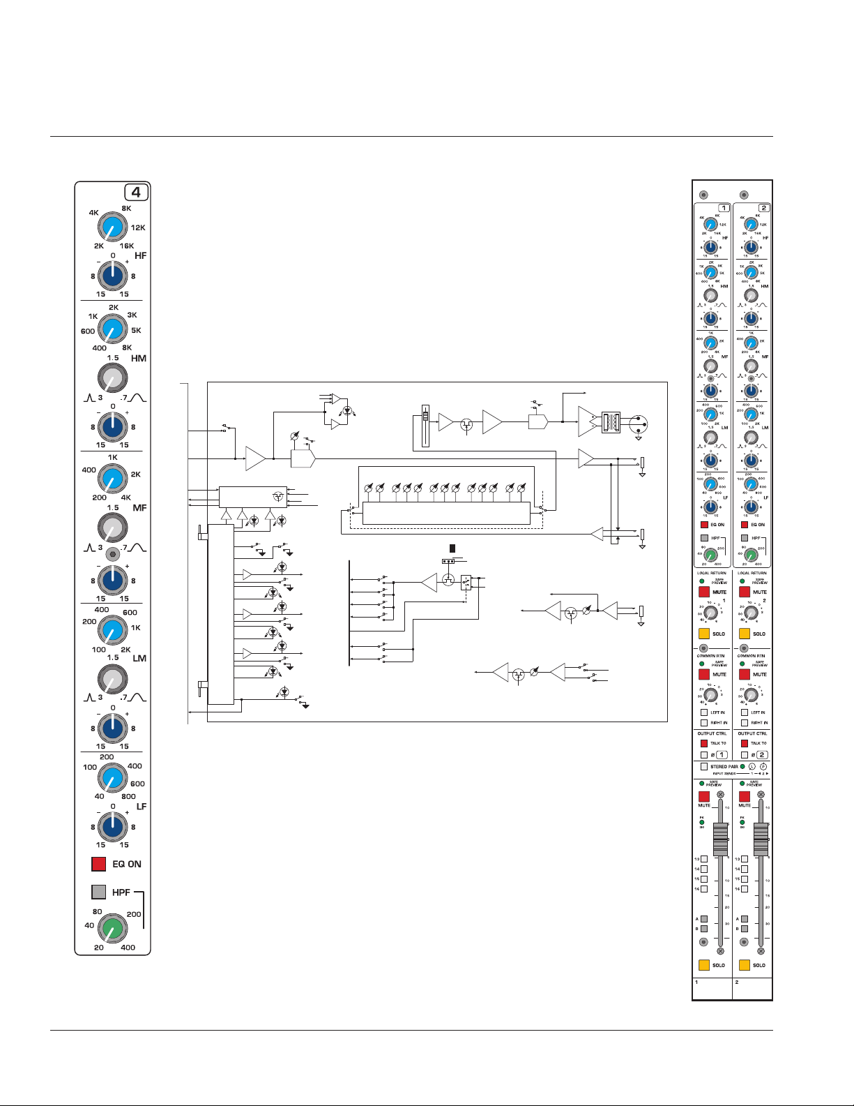
Page 21

Output EQ features
The five-band output EQ consists of two semi-parametric bands and three full parametric
bands.The High and Low bands are shelving eq with frequency select and boost/cut controls.The three mid bands, High mid, Mid, and Low mid are full parametric with frequency,
bandwidth, and boost / cut controls. All bands offer a generous overlap of adjacent operating frequencies.
High frequency—HF
Frequency
Continuously sweepable between 2 kHz and 16 kHz.
Boost / Cut 15dB boost and cut. Shelving eq.
High mid—HM
Frequency
Continuously sweepable between 400 Hz and 8 kHz.
Q (Bandwidth) Continuously variable between 3 and .7
Boost / Cut 15dB boost and cut.
Mid frequencies—MF
Frequency
Continuously sweepable between 200 Hz and 4 kHz.
Q (Bandwidth) Continuously variable between 3 and .7
Boost / Cut 15dB boost and cut.
Low mid—LM
Frequency
Continuously sweepable between 100 Hz and 2 kHz.
Q (Bandwidth) Continuously variable between 3 and .7.
Boost / Cut 15dB boost and cut.
Low frequency—LF
Frequency
Continuously sweepable between 40 Hz and 800 Hz.
Boost / Cut 15dB boost and cut. Shelving eq.
Eq on
Equalizer is on. This switch is used to activate the EQ section and can be used to
make A/B comparisons between "flat" and eq'd signals.
HPF
High pass filter is on.The high pass filter cuts low frequencies to eliminate rumble
and feedback with minimal effect on program material.
HPF Frequency
Continuously variable between 20 Hz and 400 Hz.The high pass filter has a slope of
-12 dB per octave.
p. 21
Output groups
2
Page 22
Group
Module Pair
Controls
Block diagram
p. 22
2
Output groups
X-Monitor owner’s manual
GROUP
MUTE
GRP POST
FADER
GRP PRE
FADER
LOC RTN
TO GROUP
MIX AMP
POST
LOC RTN
PRE
+6
LOCAL RTN
MUTE
LOCAL
RETURN
LEVEL
COM RTN
TO GROUP
MIX AMP
POST
+6
COMMON RTN
MUTE
LEVEL
COMMON
RETURN
LEFT
IN
RIGHT
IN
COMMON RTN
FEED L & R
FROM
MASTERS 1 & 2
Page 23

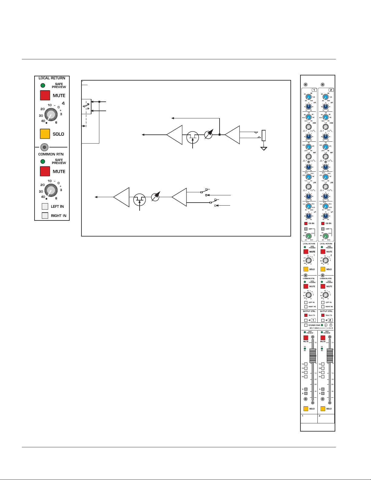
Output features
Local Return
Each Output group has its own local return.This external input appears as a 1/4” TRS balanced line level input connector on the module rear panel.
Safe preview
Safe Preview LED
See LOCAL MICROPROCESSOR CONTROL section
Mute
Mute switch
See LOCAL MICROPROCESSOR CONTROL section
Local return level
Controls the level of the local return signal into the group.
Solo switch
Pressing this momentary switch will include (illuminate) or exclude (not-illuminated)
the local return from the consoles solo system. See Master Control Section for information on Solo options.
Common Return
The X-Monitor has a pair of 1/4” TRS balanced line level input connectors on the module
rear panel.Any signals patched into these jacks are available to all of the output groups.
Safe preview
Safe Preview LED
See LOCAL MICROPROCESSOR CONTROL section
Mute
Mute switch
See LOCAL MICROPROCESSOR CONTROL section
Common return level
Controls the level of the Common return into the group.
Left in / Right in assignment buttons
These buttons are used to assign the Left, Right or both of the Common return signals to the output group.
p. 23
Output groups
2
LED
LED
Page 24

Group
Module Pair
Controls
Block diagram
T
E
EQ
p. 24
2
Output groups
X-Monitor owner’s manual
TO
INPUT
MICRO
CARDS
FROM
MASTER
MICRO
CARD
SOLO CONTROL
& SWITCHING
GROUP
MICRO
INTER-
FAC E
CARD
MUTE
SOLO
AND
STEREO
CTRL
1 OF 4
CIRCUITS
SHOWN
LEV/PAN CTRL
(TO INPUTS)
GROUP
LOCAL RTN
SOLO
SAFE
PREVIEW
SAFE
PREVIEW
SAFE
PREVIEW
GRP STEREO CTRL:
SW ON ODD GRP
LED ON EVEN GRP
SOLO
GROUP PRE FDR
POST FDR
LOC RTN PRE
GROUP
MUTE
LOCAL RTN
MUTE
COMMON RTN
MUTE
STEREO
PAIR
POST
HI MIDHF
400 TO 8K2-16K
GROUP FIVE BAND EQ
MAIN RIBBON:
TO MIX AMPS
& PRE CTRL
MIX 13
MIX 14
MIX 15
MIX 16
( FROM MASTER 2 )
WHEN SELECTED FOR STEREO PAIR OPERATION:
CORRESPONDING INPUT SEND PAIR IS RECONFIGURED
FOR LEV/PAN OPERATION (ODD IS LEV, EVEN IS PAN).
GROUP SOLO IS CHANGED FROM MONO TO STEREO:
ODD GRP SOLOS TO LEFT, EVEN GRP TO RIGHT.
GROUP
ASSIGN
TO MIXES
13 THRU 16
13
14
15
16
13-16 PRE CTRL
A
MIX A
B
MIX B
GROUP ASSIGN
TO MIXES A & B
MID LO MID
200 TO 4K 100 TO 2K
NO
+6
MIX 13-16
MUTE IF SET PRE ?
YES
GROUP
MUTE
COM RTN
TO GROUP
MIX AMP
GRP POST
FADER
GRP PRE
FADER
POST
LF
40 TO 800
TO GROUP
MIX AMP
+6
COMMON RTN
MUTE
LOC RTN
POST
LEVEL
ON
LOC R
PRE
CO
+
R
Page 25

Output features
Output Control
Talk to
The Talk back signal is assigned to the group.The level of the Talk back signal is con-
trolled by the Talk Back level control in the Master section.
Polarity reverse
The polarity of the Group output is reversed.
Stereo Pair
This switch with accompanying LED globally sets the configuration of the input
Mix pots associated with each pair of outputs. For each odd/even pair, the Mix send pots
are configured as Level / Pan.The odd numbered control sets the level, and the even numbered control adjusts the stereo placement (pan).
Safe preview
Safe Preview LED
See LOCAL MICROPROCESSOR CONTROL section
Mute
Mute switch
See LOCAL MICROPROCESSOR CONTROL section
PK / SIG
The Peak / Signal level LED indicates the output level. It illuminates green, varying in
intensity with the level of the audio signal. Red (Peak) indicates peaks and distortion. Peak
is sensed both before and after the fader, while signal level is sensed before the fader only.
Bus assignments 13, 14, 15 & 16
The Group signal is assigned to Buses 13-16 which feed Matrix 1 - 4, located above
the master control section.The feed to Buses 13-16 is normally Post-fader. All Bus 13-16
sends (from Inputs and Groups) can be globally switched to Pre-fader by using the 13-16
PRE switch, located in the Master section.
Bus A assignment
The Group signal is assigned to the main A output bus.This feed is always Post-fader.
Bus B assignment
The Group signal is assigned to the main B output bus.This feed is always Post-fader.
Group fader
The 100mm fader controls the level of the Group output and any Post-fader send.
Solo switch
Pressing this momentary switch will include (illuminate) or exclude (not-illuminated)
the group from the consoles solo system. See Master Control Section for information on
Solo options.
p. 25
Output groups
2
LED
LED
LED
Page 26

X–Monitor Group 1–4
S
e
n
d
R
t
n
I
n
s
e
r
t
Local Rtn 4
T= OUT
+
R= G COMP
S= GND
T= IN
+
R= IN
–
S= GND
1
2
3
1= GND
2= OUT
+
3= OUT
–
2
1
3
1= GND
2= IN
+
3= IN
–
XLR Female XLR Male 1/4” Output 1/4” Input
Ext Input
Local Rtn
Insert Rtn
Common Rtn
Alt Output
Insert Send
Split Out
Main Out
Group Out
Matrix Out
Monitor Out
Talkback Out
Mic In
Talkback In
4
Group Out
C
S
e
n
d
R
t
n
I
n
s
e
r
t
Local Rtn 3
3
Group Out
S
e
n
d
R
t
n
I
n
s
e
r
t
Local Rtn 2
2
Group Out
S
e
n
d
R
t
n
I
n
s
e
r
t
Local Rtn 1
1
Group Out
4321
X–Monitor Group 5–8
Common
Return R
C
Common
Return L
S
e
n
d
R
t
n
I
n
s
e
r
t
Local Rtn 8
8
Group Out
S
e
n
d
R
t
n
I
n
s
e
r
t
Local Rtn 7
7
Group Out
S
e
n
d
R
t
n
I
n
s
e
r
t
Local Rtn 6
6
Group Out
S
e
n
d
R
t
n
I
n
s
e
r
t
Local Rtn 5
5
Group Out
8765
In • MIDI • Out
To Meter Bridge
Lamp
Dim
DC IN
X–Monitor Group 9–12
1= +12V
2= +18V
3= AGND
4= AGND
5= DGND
6= +48V
7= –18V
12
345
67
C
S
e
n
d
R
t
n
I
n
s
e
r
t
Local Rtn 12
12
Group Out
S
e
n
d
R
t
n
I
n
s
e
r
t
Local Rtn 11
11
Group Out
S
e
n
d
R
t
n
I
n
s
e
r
t
Local Rtn 10
10
Group Out
S
e
n
d
R
t
n
I
n
s
e
r
t
Local Rtn 9
9
Group Out
12 11 10 9
Group Output Rear Panel
Outputs 9-12 Outputs 5-8 Outputs 1-4
Block diagram
p. 26
2
Output groups
X-Monitor owner’s manual
MAIN
RIBBON
CABLE
-
50 WAY
E
LE
TB
FEED
MIX
1 TO 12
TO
INPUT
MICRO
CARDS
FROM
MASTER
MICRO
CARD
TB TO
GROUP
SOLO CONTROL
& SWITCHING
GROUP
MICRO
INTER-
FACE
CARD
MUTE
SOLO
AND
STEREO
CTRL
1 OF 4
CIRCUITS
SHOWN
LEV/PAN CTRL
(TO INPUTS)
∑
GROUP
MIX AMP
GROUP
SOLO
SAFE
PREVIEW
SAFE
PREVIEW
SAFE
PREVIEW
GRP STEREO CTRL:
SW ON ODD GRP
LED ON EVEN GRP
LOCAL RTN
SOLO
GROUP PRE FDR
POST FDR
HPF
20 - 400HZ
HPF
GROUP PRE FDR
POST FDR
LOC RTN PRE
GROUP
MUTE
LOCAL RTN
MUTE
COMMON RTN
MUTE
STEREO
PAIR
PEAK
SIGNAL
PRESENT
POST
MAIN RIBBON:
TO MIX AMPS
& PRE CTRL
WHEN SELECTED FOR STEREO PAIR OPERATION:
CORRESPONDING INPUT SEND PAIR IS RECONFIGURED
FOR LEV/PAN OPERATION (ODD IS LEV, EVEN IS PAN).
GROUP SOLO IS CHANGED FROM MONO TO STEREO:
ODD GRP SOLOS TO LEFT, EVEN GRP TO RIGHT.
X-MONITOR GROUP
(1 OF 12 SHOWN)
GRP PRE
FADER
LEV
400 TO 8K2-16K
GROUP
ASSIGN
TO MIXES
13 THRU 16
13
MIX 13
14
MIX 14
15
MIX 15
16
MIX 16
13-16 PRE CTRL
( FROM MASTER 2 )
A
MIX A
B
MIX B
GROUP ASSIGN
TO MIXES A & B
GROUP
FADER AMP
GROUP
MUTE
LEV LEVQF LEVQF LEVF
QFF
HI MIDHF
MID LO MID
200 TO 4K 100 TO 2K
GROUP FIVE BAND EQ
YES
NO
+6
MIX 13-16
MUTE IF SET PRE ?
GROUP
MUTE
TO GROUP
MIX AMP
GROUP OUT
GROUP
RETURN
(TO EQ)
LOCAL RTN
MUTE
( TO METERBRIDGE )
XFORMER
OPTION
GC
LOCAL
RETURN
LEVEL
LEFT
IN
RIGHT
IN
COMMON RTN
FEED L & R
FROM
MASTERS 1 & 2
Ø
GRP POST
FADER
+10
EQ
ON
LF
40 TO 800
GRP POST
FADER
COM RTN
POST
GRP PRE
FADER
TO GROUP
MIX AMP
+6
COMMON RTN
MUTE
LOC RTN
LEVEL
POST
LOC RTN
PRE
COMMON
RETURN
+6
GROUP
BAL OUT
GROUP
INSERT SEND
BAL
INSERT RTN
Page 27

Output features
Output Connectors - Each Group
Group Out
Male XLR carries the post fader Group output signal. This output is designed to
drive output impedances greater than 600 ohms. The associated group metering follows
signal levels that appear on this output connector.
Insert Send & Return
Separate 1/4" TRS jacks are used for pre fader insert connectors. Signal is fed
full time to ground compensated insert send connector. When a connector is
plugged into the fully balanced 1/4" return jack, the internal signal path is broken, with the
external (processed) signal continuing its signal flow through the module. This pair of connectors is used to "patch" external signal processing such as 1/3 octave EQ into the module’s signal path.
Local return
1/4” TRS jack- Balanced (can accept balanced or unbalanced inputs). This input
feeds the group by way of the front panel "Local Return" controls. This may be used to
bring effects inputs or external mixes into the mix group output channel.
Common return (On Rear of Module 5-8)
A pair of 1/4” TRS jacks- Balanced (can accept balanced or unbalanced inputs).
Signals into these jacks are sent to the Common-return controls on the Master module.
Two separate inputs are provided to allow a common left and right signal to feed any of the
12 group mix output channels. Master On switches are provided as well as pre and post
fader Solo switching and master level controls. This section may be used to feed reference
or click tracks to any of the 12 main output mixes, or common ambience effects.
p. 27
Output groups
2
+
T= OUT
R= G COMP
S= GND
+
T= IN
–
R= IN
S= GND
+
T= IN
–
R= IN
S= GND
Page 28

Block diagrams
p. 28
3
Master section
X-Monitor owner’s manual
MIX AMP
A
MIX A
∑
GC
TALKBACK
TB
FEED
MIX A - LOCATED ON MASTER 1
MIX AMP
B
MIX B
∑
GC
TALKBACK
TB
FEED
MIX B - LOCATED ON MASTER 2
MATRIX TALKBACK
(FROM MASTER 2)
OUT 13
OUT 14
MATRIX 1 (2)
MIX AMP
∑
OUT 15
13 (14)
13 (14)
MIX
OUT
OUT 16
TO MATRIX MIXES
MATRIX TALKBACK
(FROM MASTER 2)
OUT 13
OUT 14
EXT IN
∑
MIX 13 (14)
MIX AMP
MATRIX 1 (2) - LOCATED ON MASTER 1 (2)
( MATRIX 1 SHOWN, MATRIX 2 IS IDENTICAL )
MATRIX 3 (4)
MIX AMP
∑
OUT 15
15 (16)
15 (16)
MIX
OUT
OUT 16
TO MATRIX MIXES
TO MIX A (B)
EXT IN
∑
MIX 15 (16)
MIX AMP
MATRIX 3 (4) - LOCATED ON MASTER 3 (4)
( MATRIX 3 SHOWN, MATRIX 4 IS IDENTICAL )
FROM MATRIX 3 (4)
INSERT RETURN
PATH SWITCHING BETWEEN
MATRIX AND MAIN MIX ONLY
AVAILABLE ON EQ 1 & 2
FROM MATRIX 1 (2)
INSERT RETURN
FROM MIX A (B)
INSERT RETURN
MIX A
INSERT
SEND RTN
MIX B
INSERT
SEND RTN
GC
GC
X-MONITOR MASTER MODULE (UPPER AREA)
5-BAND EQ
MIX A
TO EQ 1
INST RTN
SWITCH BETWEEN
MTX 1 OR MIX A
PRE-FADER
POST-FADER
PK
SIG
5-BAND EQ
MIX B
INST RTN
SWITCH BETWEEN
MTX 2 OR MIX B
PRE-FADER
POST-FADER
PK
SIG
MATRIX
INSERT
MATRIX
EXT IN
MATRIX
INSERT
MATRIX
EXT IN
TO BE ADDED INTO
MIX A AND B
MATRIX
INST RTN
MATRIX
INST RTN
SEND RTN
SEND RTN
ALLOWS MATRIX 3 AND 4
5-BAND EQ - NORMALLY ON MATRIX PATH
FR
LEV
LEVFRLEVFRLEVFRLEV
400 TO 8K 200 TO 4K 100 TO 2K12K
A - PRE
SELECT
FADER
-
TO SOLO
&
MICRO
TO EQ 2
B - PRE
SELECT
FADER
-
TO SOLO
&
MICRO
5-BAND EQ
TO EQ 1 (2)
—
CAN SELECT EQ
TO BE ON EITHER
MATRIX 1 (2) -DEFAULT
OR MIX A (B)-SWITCHED
MATRIX 1 AND 2 HAVE EQS
THAT CAN BE SWITCHED
INTO THE MIX A AND B
PATHS INSTEAD OF THE
DEFAULT MATRIX PATH
5-BAND EQ
TO EQ 3 (4)
—
ALWAYS ON
MATRIX PATH
MATRIX 3 & 4 HAVE DEDICATED
EQS, AND THE MATRIX
OUTPUTS CAN BE ADDED
INTO MIXES A AND B
MATRIX 3 (4)
TO A (B)
( 1 OF 4 SHOWN )
MIDHI MIDHF
LO MID
FIVE BAND EQ (1 OF 4)
MIX A
LEVEL
+10
MIX A
MUTE
MUTE AND SOLO SWITCHING
(MICRO CONTROLLED)
MIX B
LEVEL
+10
MIX B
MUTE
MUTE AND SOLO SWITCHING
(MICRO CONTROLLED)
MATRIX
LEVEL
MATRIX
PRE-FADER
MATRIX
MUTE
MUTE AND SOLO SWITCHING
(MICRO CONTROLLED)
TO SOLO BUS & MICRO INTERFACE
MATRIX
LEVEL
MATRIX
PRE-FADER
MATRIX
MUTE
MUTE AND SOLO SWITCHING
(MICRO CONTROLLED)
TO SOLO BUS & MICRO INTERFACE
MATRIX
PRE-FADER
MATRIX
POST-FADER
EQ
ON
LF
20 TO 400
A - POST
FADER
B - POST
FADER
+10
+10
TO MATRIX 3 (4)
PRE-FADER
Ø
Ø
MTX - POST
FADER
MATRIX
POST-FADER
EQ TO
MIX A (B)
MUTE
SOLO
MUTE
SOLO
PATH SWITCHING BETWEEN
MATRIX AND MAIN MIX ONLY
XFORMER
OPTION
XFORMER
OPTION
MATRIX 1 (2)
MUTE
SOLO
MATRIX 3 (4)
MUTE
SOLO
TO MATRIX 1 (2)
PRE-FADER
TO MIX A (B)
PRE-FADER
AVAILABLE ON EQ 1 & 2
MIX A
BAL OUT
MIX B
BAL OUT
BAL OUT
BAL OUT
M1
SIG
PK
TB
Ø
MUTE
SAFE
PREV
AB
SOLO
MIX A & B
CONTROLS
LOCATED ON
MASTER 1
SEE BLOCK DIAG
FOR DETAILS >
X-Monitor Block Diagram
X-MONITOR BLK DIA-REV1.2-7/27/01
SOLO
COM L
COM RTN - L
MASTER LEV
COMMON RETURN
LEFT RIGHT
ON
+10
SOLO CONTROL
COMMON RETURN
FROM
POST-FADER
CTRL
ON
TO SOLO
MIX L&R
+10
TALKBACK
AUDIO
COM RTN - R
MASTER LEV
COMMON RETURN
LEFT & RIGHT
TO ALL GROUPS
SOLO
COM R
SOLO
AUTO
MUTE
TALK TO
MATRIX
13-16
PRE-FADE
SOLO
CTRL
MONITOR
MUTE
TB AUDIO
TO MATRIX
1 TRU 4
TO INPUTS
AND GROUPS
X-MONITOR MASTER MODULE (LOWER AREA)
MONITOR OUT
LEFT RIGHT
SUM
MONO
SOLO
LEFT RIGHT
AUDIO
CHANGES MIXES
13 THRU 16
TO PRE-FADER INSTEAD
OF DEFAULT POST-FADER
EXTERNAL TALKBACK
M2 M3
OUT IN
TB
OUT
MONITOR
LEVEL
TB
TB
LEVEL
( A )
PINK
NOISE
PINK
NOISE
GEN
TO METER BRIDGE
L SOLO R
∑
SOLO LEFT
SOLO
SOLO
MIX
AUDIO
AMPS
M4
TB
LEVEL
( B )
EXT TB
ON
MIX A
- PRE MIX B
TB AUDIO
(TO RIBBON)
TAP TO
LATCH
TALK ON
-
TB
HOLD FOR
SWITCH
MOMENTARY
LOGIC
+48V
TALK BACK
+48 VOLT
OFF / ON
LOCATED UNDER ARMREST
HEADPHONE
TALK BACK
IN
LEFT RIGHT
GC
ALT
LEVEL
SOLO
AUDIO
RIGHT
SOLO
AUDIO
LEFT
OUT
LEFT RIGHT
GC
A-B
TO ALT
EXT
MON
IN
HP
LEVEL
M
A
N
U
A
L
M
U
T
E
S
C
E
N
E
S
MICRO MUTE CONTROL
EXT MONITOR IN
ALTERNATE OUT
∑
SOLO CONTROL & STATUS
- ACTIVE -
PRIORITY
PRESSED
128
SEQUENCED
SCENE
EDIT
EDIT
PREVIEW
SAFE
SINGLE
MICRO
SCENE
UTILITY
SEQUENCE
GO
SCENE ON
1
2
3
4
5
6
7
8
SOLO RIGHT
INPUT
OUTPUT
SOLO
ACTIVE
CLEAR
INPUT
LAST
POST
FADER
MASTER
MICRO
INTER-
FACE
CARD
INPUT &
GROUP
CONTROL
TO
LEFT
SIDE
GROUP
MICRO
CARDS
-
TO
RIGHT
SIDE
-
INPUT
MICRO
CARDS
Page 29

Master Module Summary
The MASTER module of X-Monitor serves multiple purpose.
The module contains the following sections:
• Matrix Output EQ and high pass filter
• Matrix Output mix
• Matrix Output control
• A and B Output control with 100mm faders
• Common Return master control
• Microprocessor Mute Controller
• Monitor control with 100mm fader
• Alternate and Headphone Outputs
• Talkback Control
• Solo Control
Matrix section
X-Monitor includes a unique matrix output system. Signal is assigned from Input and/or
Group modules into a mix bus section. These mix buses contains no front panel control or
output connectors, but rather are a source for the matrix system. Four output matrixes are
included. Each has separate control of master levels from mixes 13, 14, 15, and 16, as well as
an external input connector. Each matrix output includes level control, Solo switch and
microprocessor mute system.A five-band output EQ is available on each matrix output.
The matrix section may be used in a number of different ways:
Effects Sends - The most basic application of the matrix system is to feed effects devices from
individual input channels without any required re-patching. When used in this application,
matrix 1 would have mix 13 level control set to unity with all other level controls on matrix
1 (except output level) set fully counter-clockwise (or off). Matrix 2 would have mix 14 level
control set to unity with all other level controls on matrix 2 (except output level) set fully
counter-clockwise (or off). This same set up would be repeated with matrix 3 (mix 15) and
matrix 4 (mix16).
p. 29
Master section
3
Page 30

MIX AMP
p. 30
3
Master section
X-Monitor owner’s manual
)
TO MATRIX MIXES
TO MIX A (B)
MATRIX 3 (4) - LOCATED ON MASTER 3 (4)
( MATRIX 3 SHOWN, MATRIX 4 IS IDENTICAL )
FROM MATRIX 3 (4)
INSERT RETURN
PATH SWITCHING BETWEEN
MATRIX AND MAIN MIX ONLY
AVAILABLE ON EQ 1 & 2
FROM MATRIX 1 (2)
INSERT RETURN
FROM MIX A (B)
INSERT RETURN
ALLOWS MATRIX 3 AND 4
TO BE ADDED INTO
MIX A AND B
5-BAND EQ - NORMALLY ON MATRIX PATH
FR
LEV
LEV
400 TO 8K 200 TO 4K 100 TO 2K12K
MATRIX 3 (4)
TO A (B)
( 1 OF 4 SHOWN )
FR
FIVE BAND EQ (1 OF 4)
FR
LEV
MIDHI MIDHF
LO MID
LEV
MATRIX
PRE-FADER
MATRIX
POST-FADER
FR
LF
20 TO 400
LEV
TO MATRIX 3 (4)
EQ
ON
PRE-FADER
EQ TO
MIX A (B)
PATH SWITCHING BETWEEN
MATRIX AND MAIN MIX ONLY
TO MATRIX 1 (2)
PRE-FADER
TO MIX A (B)
PRE-FADER
AVAILABLE ON EQ 1 & 2
Page 31

Output EQ features
The five-band output EQ consists of a high-freq shelving band followed by four semi-parametric bell-shaped bands.The four bands have frequency and boost / cut controls. All bands
offer a generous overlap of adjacent operating frequencies.These Output EQs are normally assigned to the Matrix Outputs.The first two (1 & 2) can be switched over to the Bus A
and Bus B Outputs with the EQ to A (B) switches.
high frequency—HF
Boost / Cut
15dB boost and cut. Shelving eq at 12kHz.
high mid—HM
Frequency
Continuously sweepable between 400 Hz and 8 kHz.
Boost / Cut 15dB boost and cut.
mid frequencies—MF
Frequency
Continuously sweepable between 200 Hz and 4 kHz.
Boost / Cut 15dB boost and cut.
Low mid—LM
Frequency
Continuously sweepable between 100 Hz and 2 kHz.
Boost / Cut 15dB boost and cut.
Low frequency—LF
Frequency
Continuously sweepable between 20 Hz and 400 Hz.
Boost / Cut 15dB boost and cut.
Eq on
Equalizer is on. This switch is used to activate the EQ section and can be used to make
A/B comparisons between "flat" and eq'd signals.
EQ TO A (B)
The EQ is in the Matrix signal path, the Bus A (B) path is flat (no EQ).
The EQ is switched to the Bus A(B) signal path, the Matrix path is flat (no EQ).
MTX TO A (B)
The post-fader Matrix signal is fed into the Bus A (B) mix. Matrix 3 can feed Bus A,
Matrix 4 can feed Bus B.An internal jumper allows this feed to be changed to Matrix prefader.
p. 31
Master section
1
Page 32

MATRIX 1 (2)
LOCATED ON MASTER 1 (2)
p. 32
3
Master Section
X-Monitor owner’s manual
( MATRIX 1 SHOWN, MATRIX 2 IS IDENTICAL )
MATRIX TALKBACK
(FROM MASTER 2)
OUT 13
OUT 14
OUT 15
OUT 16
MIX
15 (16)
OUT
15 (16)
∑
TO MATRIX MIXES
TO MIX A (B)
MATRIX 3 (4) - LOCATED ON MASTER 3 (4)
( MATRIX 3 SHOWN, MATRIX 4 IS IDENTICAL )
-
MATRIX 3 (4)
MIX AMP
∑
EXT IN
MIX 15 (16)
MIX AMP
FROM MATRIX 3 (4)
INSERT RETURN
PATH SWITCHING BETWEEN
MATRIX AND MAIN MIX ONLY
AVAILABLE ON EQ 1 & 2
FROM MATRIX 1 (2)
INSERT RETURN
FROM MIX A (B)
INSERT RETURN
GC
MATRIX
INSERT
SEND RTN
MATRIX
EXT IN
ALLOWS MATRIX 3 AND 4
TO BE ADDED INTO
MIX A AND B
5-BAND EQ - NORMALLY ON MATRIX PATH
FR
LEV
400 TO 8K 200 TO 4K 100 TO 2K12K
MATRIX
INST RTN
TO EQ 3 (4)
—
ALWAYS ON
MATRIX PATH
MATRIX 3 & 4 HAVE DEDICATED
EQS, AND THE MATRIX
OUTPUTS CAN BE ADDED
INTO MIXES A AND B
MATRIX 3 (4)
TO A (B)
( 1 OF 4 SHOWN )
FR
5-BAND EQ
LEV
LEV
MIDHI MIDHF
FIVE BAND EQ (1 OF 4)
MUTE
SOLO
TO MATRIX 1 (2)
PRE-FADER
TO MIX A (B)
PRE-FADER
MATRIX 3 (4)
BAL OUT
MATRIX
LEVEL
MATRIX
PRE-FADER
MATRIX
MUTE
MUTE AND SOLO SWITCHING
(MICRO CONTROLLED)
TO SOLO BUS & MICRO INTERFACE
MATRIX
PRE-FADER
MATRIX
POST-FADER
EQ
FR
LO MID
LEV
FR
20 TO 400
ON
LEV
LF
MATRIX
POST-FADER
+10
TO MATRIX 3 (4)
PRE-FADER
EQ TO
MIX A (B)
PATH SWITCHING BETWEEN
MATRIX AND MAIN MIX ONLY
AVAILABLE ON EQ 1 & 2
Page 33

Matrix Mix features
The Matrix section is fed from the internal Bus 13 thru 16 signals.These internal buses get
their signal from the Input and Groups via the Bus 13-16 assignment switches.The assignment to Buses 13-16 is normally post-fader, a master switch globally changes this to prefader. Each Matrix also has its own External input which can be mixed in with the Bus 1316 signals.The External Input signal comes from the four 1/4” TRS jacks located on the rear
of the Master Module.
13- Bus 13 mix level into the Matrix.
14- Bus 14 mix level into the Matrix.
15- Bus 15 mix level into the Matrix.
16- Bus 16 mix level into the Matrix.
EXT IN- External Input mix level into the Matrix, from TRS jack on rear panel
MUTE- Micro-controllable mute control. See Micro-instructions for operation.
LEV- Master Level control for Matrix output.
SOLO- Allows monitoring of the Matrix signal in the Solo system.This feed follows
the master SOLO MODE switch. Pre-fader monitors the actual Matrix mix-bus, Post-Fader
monitors the Matrix signal after the Master Level and Mute controls.In the X-Monitor, the
Solo system makes a distinction between Inputs and Outputs.The Matrix Solo is treated as
an Output by the Solo system. See the Solo Section of the manual for details on the different Solo functions and modes.
p. 33
Master section
3
Page 34

Block Diagram
Module
p.34
3
Master section
X-Monitor owner’s manual
MIX AMP
A
∑
TALKBACK
MIX A - LOCATED ON MASTER 1
MIX AMP
B
∑
TALKBACK
FEED
MIX A
FEED
MIX B
TB
TB
MIX B - LOCATED ON MASTER 2
X-MONITOR MASTER MODULE (UPPER AREA)
MIX A
INSERT
SEND RTN
GC
PRE-FADER
POST-FADER
MIX B
INSERT
SEND RTN
GC
PRE-FADER
POST-FADER
MIX A
INST RTN
MIX B
INST RTN
5-BAND EQ
TO EQ 1
SELECT
-
SWITCH BETWEEN
MTX 1 OR MIX A
PK
TO SOLO
SIG
MICRO
5-BAND EQ
TO EQ 2
SELECT
-
SWITCH BETWEEN
MTX 2 OR MIX B
PK
TO SOLO
SIG
MICRO
A - PRE
FADER
&
B - PRE
FADER
&
MIX A
LEVEL
+10
MIX A
MUTE
MUTE AND SOLO SWITCHING
(MICRO CONTROLLED)
MIX B
LEVEL
+10
MIX B
MUTE
MUTE AND SOLO SWITCHING
(MICRO CONTROLLED)
A - POST
FADER
B - POST
FADER
Ø
MUTE
SOLO
Ø
MUTE
SOLO
XFORMER
OPTION
XFORMER
OPTION
MIX A
BAL OUT
MIX B
BAL OUT
Page 35

Bus A & Bus B master controls
The Bus A and Bus B circuits are internal mix buses that can be fed from any Input or Group
module by using the A and B assignment switches located next to the fader on each module.The feed to these buses is always post-fader.These buses are similar to the Bus 13-16
internal buses except that:
1) The feed to Bus A & B is always post-fader. Feed to Bus 13-16 can be globally switched
to pre-fader.
2) The Bus A & B circuits have their own master faders with TB, Polarity, programmable
Mute and Solo switches. Bus 13-16 circuits only feed the matrix section.
SIG/ PK (Signal/Peak)
This dual-color LED shows the signal conditions within the Bus A (B) circuits.Varying
intensity GREEN shows signal present at the mix bus, RED indicates that signals are
approaching or have exceeded clip levels anywhere within the circuits.The Peak circuit monitors the mix bus and the pre and post fader signals.The LED will illuminate RED when any
signal comes within 3dB of clipping.
TLK TO (Talk To)
This switch (when depressed) allows the signal from the TalkBack section to be mixed
into the Bus A (B) circuits.
Ø (Polarity Reverse)
The polarity of the Bus A (B) output is reversed when this switch is depressed.
MUTE (Micro-Programmable)
This switch mutes the Bus A (B) outputs.The SAFE/PREV LED located directly below
the switch shows mico-mute status.See the Mico Section of the Owner’s manual for details
on its operation.
Fader
This 100mm fader controls the level of the post-fader output from Bus A (B)
SOLO
This switch is used to add/remove the Bus A (B) signal from the Solo Bus.The internal LED (Yel) will illuminate whenever the Solo is active. In the X-Monitor, the Solo system
makes a distinction between Inputs and Outputs.The Bus A (B) solo is treated as an Output
by the Solo system. Both the pre-fader and post-fader signals can be monitored, See the
Solo Section of the manual for details on the different solo functions and modes.
p. 35
Master section
3
LED
Page 36

Group Module Panel
Master Module Panel
Rear Panel (Group 5-8)
X–Monitor Group 5–8
Common
Return R
C
Common
Return L
S
e
n
d
R
t
n
I
n
s
e
r
t
Local Rtn 8
8
Group Out
S
e
n
d
R
t
n
I
n
s
e
r
t
Local Rtn 7
7
Group Out
S
e
n
d
R
t
n
I
n
s
e
r
t
Local Rtn 6
6
Group Out
S
e
n
d
R
t
n
I
n
s
e
r
t
Local Rtn 5
5
Group Out
8765
block diagram (Group)
block diagram (Master)
p. 36
3
Master section
X-Monitor owner’s manual
COMMON RETURN
LEFT RIGHT
COMMON
COM RTN
TO GROUP
MIX AMP
POST
+6
LEVEL
COMMON RTN
MUTE
RETURN
LEFT
IN
RIGHT
IN
COMMON RTN
FEED L & R
FROM
MASTERS 1 & 2
ON
COM RTN - L
MASTER LEV
SOLO
COM L
+10
SOLO CONTROL
COMMON RETURN
FROM
POST-FADER
CTRL
ON
TO SOLO
MIX L&R
+10
COM RTN - R
MASTER LEV
COMMON RETURN
LEFT & RIGHT
TO ALL GROUPS
SOLO
COM R
MONITOR
MUTE
SOLO
AUTO
MUTE
Page 37

Common Return Inputs
Two separate inputs are provided to allow a common left and right signal to feed any
of the 12 group mix output channels. Master On switches are provided as well as
pre and post fader Solo switching and master level controls. This section may be
used to feed reference or click tracks to any of the 12 main output mixes, or common ambience effects.The input jacks for the Common Returns are located on the
rear of Group Module 5-8.They are balanced 1/4” TRS jacks.
Controls (Master Module)
ON (Left & Right)
Feeds the buffered input signals into the Common Return control section.
Master Level (Left & Right)
This pot controls the overall level of the Common Input.This post-level signal is what
is distributed to the twelve Group modules.
Solo
This switch is used to add/remove the Common Return signal from the Solo Bus.The
internal LED (Yel) will illuminate whenever the Solo is active. In the X-Monitor,the Solo system makes a distinction between Inputs and Outputs.The Common Return solo is treated as an Input by the Solo system. Both the pre-fader and post-fader signals can be monitored, See the Solo Section of the manual for details on the different solo functions and
modes.
Controls (Group Module)
MUTE (Micro-Programmable)
This switch mutes the combined mix of the Common Returns to the Group Mix bus.
The SAFE/PREV LED located directly above the switch shows mico-mute status. See the
Mico Section of the Owner’s manual for details on its operation.
Level
This control adjusts the overall level of the combined Common returns to the Group
mix bus.This pot can be set independently for each Group to allow a different level of the
Common Returns to appear in each Group.The overall level of ALL the Common Return
signals is controlled at the Master Module.
Left In
When this switch is depressed, the Common Return LEFT signal from the Master
Module is fed to the combining circuit driving the Level pot.
Right In
When this switch is depressed, the Common Return RIGHT signal from the Master
Module is fed to the combining circuit driving the Level pot.
p. 37
Master section
3
Page 38

module
(Solo Controls)
Rear panel
(Master)
module
(TB Controls)
Solo & TalkBack block diagram
p. 38
3
Master section
X-Monitor owner’s manual
X-MONITOR MASTER MODULE (LOWER AREA)
OUT
RIGHT
MONITOR
LEVEL
RIGHT
S MIXES
RU 16
ER INSTEAD
POST-FADER
EXTERNAL TALKBACK
M2 M3
OUT IN
TB
OUT
TB
LEVEL
( B )
EXT TB
ON
(TO RIBBON)
TB AUDIO
TB
TAP TO
LATCH
TB
LEVEL
( A )
PINK
NOISE
GEN
PINK
NOISE
TB
SWITCH
LOGIC
TALK ON
+48V
-
HOLD FOR
MOMENTARY
TALK BACK
+48 VOLT
OFF / ON
LOCATED UNDER ARMREST
TALK BACK
IN
ALTERNATE OUT
M4
LEFT RIGHT
MIX A
- PRE MIX B
HEADPHONE
OUT
GC
LEVEL
ALT
SOLO
AUDIO
RIGHT
SOLO
AUDIO
LEFT
GC
A-B
TO ALT
EXT
MON
IN
EXT MONITOR IN
LEFT RIGHT
HP
LEVEL
TO METER BRIDGE
L SOLO R
SOLO
AUDIO
SOLO CONTROL & STATUS
128
SEQUENCED
SCENE
EDIT
PREVIEW
SINGLE
SCENE
SEQUENCE
SCENE ON
1
2
M
A
N
U
3
A
L
4
M
U
T
E
5
S
C
6
E
N
E
S
7
8
SOLO
MIX
AMPS
UTILITY
EDIT
SAFE
MICRO
GO
∑
SOLO LEFT
SOLO RIGHT
∑
INPUT
- ACTIVE OUTPUT
SOLO
ACTIVE
CLEAR
INPUT
PRIORITY
LAST
PRESSED
POST
FADER
MASTER
MICRO
INTER-
FACE
CARD
-
INPUT &
GROUP
CONTROL
MICRO MUTE CONTROL
Out
Insert
Return
Monitor
Out
R
TB
Out
Matrix 4
Matrix 3
Ext
In
Out Out Out
4321
Insert
Send
Insert
Return
Monitor
Out
L
Ext
TB
In
Ext Mon
Input
R
Ext
In
Insert
Send
Ext Mon
Input
L
X–Monitor Master
Main
Out
B
Insert
Return
Insert
Return
Matrix 2
Insert
Send
Insert
Send
Out
Ext
In
Alt
B
Main
Out
A
Insert
Return
Insert
Return
Matrix 1
Insert
Send
Insert
Send
Ext
In
Alt
Out
A
C
Page 39

Talkback features
Talkback control
The talkback section provides the facilities to take either an external input signal, or an internally generated pink noise signal and route it to the consoles outputs.This is useful for making
announcements from the mix position and for performing system diagnostics when other signal
sources are not readily available.
Talkback Sources
The talkback control section can get its signal from three possible sources.
1) TB IN- An XLR jack located below the consoles armrest. Suited for Mic level inputs, Phantom
power is available on this jack via an internal jumper.
2) Pink noise generator,The internal noise generator can be selected with the PINK NOISE
switch. Depressing this switch both activates the internal noise generator and de-selects the TB
IN jack.Whichever of these two sources is selected is considered the “Internal” signal. NOTE: It
is ONLY this “Internal” signal that is fed to the External TB Out XLR jack when the TALK-
BACK OUT switch is depressed.
3) External TB IN- This XLR is located on the rear of the Master Module. Its line-level signal is
mixed with the “Internal” signal whenever EXT TB ON is depressed.The combination of this
Ext Input and the Internal source is what is fed to the modules when the Talkback is active.
Pink Noise switch
The talkback control section gets its internal source signal from the Talkback XLR mic
inputs.
The talkback control section gets its internal signal from the pink noise generator.
Talkback Level
This control sets the level of the talkback signal,whether it is from the external input or
consists of the internal pink noise generator.
TB ON - Talk back on
This "soft" switch activates the Talkback section. An internal RED LED will illuminate to indicate
that the TB is active.The Talkback section must be activate in order for any of its features to
work.
Tap switch once - This will toggle the Talkback section on and off.Tap once to turn it on,
when you're done tap it again to turn it off.
Press and hold - The switch will work as a momentary button if pressed and held for
more than two seconds.While the button is down, the Talkback section is activated.When you
release the button, the Talkback section shuts off.
EXT TB ON
When this switch is depressed, the signal from the rear-panel Ext TB In jack is mixed with
the internal TB signal.The TB Level pot and TALK ON switch control this input.
TALKBACK OUT
When this switch is depressed, the internal signal from the TB section is sent to the rearpanel Ext TB Out jack.The TB Level pot and TALK ON switch control this output.
p. 39
Master section
3
Page 40

module
(Mon Controls)
Rear panel
(Master)
module
(HP Controls)
Monitor & HP block diagrams
O
p. 40
3
Master section
X-Monitor owner’s manual
X-M
MUTE
1 TRU 4
MONITOR OUT
LEFT RIGHT
MONITOR
LEVEL
SUM
MONO
SOLO
LEFT RIGHT
AUDIO
CHANGES MIXES
13 THRU 16
TO PRE-FADER INSTEAD
OF DEFAULT POST-FADER
M2
ETURN
RIGHT
+10
OLO
L&R
TALKBACK
AUDIO
COM RTN - R
MASTER LEV
COMMON RETURN
LEFT & RIGHT
TO ALL GROUPS
SOLO
COM R
SOLO
AUTO
MUTE
TALK TO
MATRIX
13-16
PRE-FADE
MONITOR
SOLO
CTRL
TB AUDIO
TO MATRIX
TO INPUTS
AND GROUPS
R AREA)
M4
MIX A
- PRE MIX B
Y
UNDER ARMREST
HEADPHONE
K
OUT
ALTERNATE OUT
LEFT RIGHT
GC
GC
ALT
LEVEL
TO ALT
SOLO
AUDIO
RIGHT
SOLO
AUDIO
LEFT
EXT
MON
EXT MONITOR IN
LEFT RIGHT
A-B
IN
HP
LEVEL
TO METER BRIDGE
L SOLO R
SOLO
AUDIO
SOLO CONTROL & STATUS
128
SEQUENCED
SCENE
EDIT
PREVIEW
SINGLE
SCENE
SEQUENCE
SCENE ON
1
2
M
A
N
U
3
A
L
4
M
U
T
E
5
S
C
6
E
N
E
S
7
8
SOLO
MIX
AMPS
EDIT
SAFE
MICRO
UTILITY
GO
∑
SOLO LEFT
SOLO RIGHT
∑
INPUT
- ACTIVE OUTPUT
SOLO
ACTIVE
CLEAR
INPUT
PRIORITY
LAST
PRESSED
POST
FADER
MASTER
MICRO
INTER-
FACE
CARD
-
INPUT &
GROUP
CONTROL
MICRO MUTE CONTROL
Out
Insert
Return
Monitor
Out
R
TB
Out
Matrix 4
Matrix 3
Ext
In
Out Out Out
4321
Insert
Send
Insert
Return
Monitor
Out
L
Ext
TB
In
Ext Mon
Input
R
Ext
In
Insert
Send
Return
Main
Out
B
Return
Ext Mon
Input
L
X–Monitor Master
Insert
Insert
Matrix 2
Insert
Send
Insert
Ext
In
Send
Alt
Out
B
Main
Out
A
Insert
Return
Insert
Return
Matrix 1
Insert
Send
Insert
Send
Ext
In
Alt
Out
A
C
Page 41

Monitor, headphone & alt out features
Monitor, headphone & alt out control
The Monitor output normally follows the Solo system, any signals that are solo’d can
be heard in both the Headphone and Monitor outputs. A Mute button allows the
operator to silence the Monitor output, while an EXT MON IN switch permits the
operator to monitor an external source on the headphones.A pair of 1/4” TRS jacks
on the rear of the Master Module bring the Ext Input into the headphones.
Additionally, another output is provided (Alt Out) which also normally follows the
Solo system.An RTA or similar piece of monitoring gear can be driven from this output. For added versatility, the Bus A & B signals can alternately be fed to this output.
monitor controls
MUTE (Monitor Mute)
The Monitor output is turned off.The XLR output jacks are located on the rear
of the Master Module.
Fader (Monitor Level)
This 100mm fader controls the level of the Monitor Out.
SUM MONO (Monitor Source Select)
The Monitor Out is stereo (for Stereo signals).
The Monitor Outs are summed to mono.This setting is useful if you are using
a single wedge as your monitor speaker.
Headphone controls
EXT MON IN (Headphone Source Select)
The Headphones follow the Solo system.
The Headphones are fed from the Ext Mon In jacks on the rear.
Lev (Headphone Level)
This pot controls the level of the headphone output.The headphone jack is
located under the armrest, next to the TB In jack.
Alt-out controls
Lev (Alt-Out Level)
This pot controls the level of the Alt Output.The TRS output jacks are located
on the rear of the Master module.
A-B TO ALT (Alt-Out Source Select)
The Alt Out follows the Solo system.
The Alt Out is fed from the Bus A & B signals.These signals are not affected by
the Bus A & B main faders.
p. 41
Master section
3
Page 42

module
(Solo Controls)
Solo block diagram
p. 42
3
Master section
X-Monitor owner’s manual
MODULE (LOWER AREA)
KBACK
IN
TB
WITCH
LOGIC
TB
LEVEL
( B )
TALK ON
+48V
M3
EXT TB
ON
TB AUDIO
(TO RIBBON)
TAP TO
LATCH
-
HOLD FOR
MOMENTARY
TALK BACK
+48 VOLT
OFF / ON
LOCATED UNDER ARMREST
TALK BACK
IN
M4
MIX A
- PRE MIX B
HEADPHONE
ALTERNATE OUT
LEFT RIGHT
GC
OUT
ALT
LEVEL
SOLO
AUDIO
RIGHT
SOLO
AUDIO
LEFT
GC
EXT MONITOR IN
LEFT RIGHT
A-B
TO ALT
EXT
MON
IN
LEVEL
HP
TO METER BRIDGE
L SOLO R
SOLO
AUDIO
SOLO CONTROL & STATUS
128
SEQUENCED
SCENE
EDIT
PREVIEW
SINGLE
SCENE
SEQUENCE
SCENE ON
1
2
M
A
N
U
3
A
L
4
M
U
T
E
5
S
C
6
E
N
E
S
7
8
SOLO
MIX
AMPS
MICRO
UTILITY
EDIT
SAFE
GO
∑
SOLO LEFT
SOLO RIGHT
∑
INPUT
- ACTIVE OUTPUT
SOLO
ACTIVE
CLEAR
INPUT
PRIORITY
LAST
PRESSED
POST
FADER
MASTER
MICRO
INTER-
FAC E
CARD
-
INPUT &
GROUP
CONTROL
TO
LEFT
SIDE
-
GROUP
MICRO
CARDS
TO
RIGHT
SIDE
-
INPUT
MICRO
CARDS
MICRO MUTE CONTROL
Page 43

Solo features
Solo Control System
The X-Monitor is equipped with a powerful stereo solo system.Any input or output
can be monitored pre-level (PFL) or after level control (AFL), as desired.The system
may be set as additive (all channels selected on solo bus), or exclusive, so that only
one solo switch is active at a time ("last pressed"). Input Priority Mode is switchselectable.This mode gives higher priority to the Inputs and automatically de-selects
any solo’d outputs when an Input is solo’d. When the Input is de-selected(or the
CLEAR sw is pressed), the previously active Output solo(s) return. Individual LEDs
indicate whether the solo system was triggered by an Input or Output. Any signal
being solo'd appears on the dedicated left and right solo meters on the meter bridge,
and is audible in the stereo headphone system and the Monitor outputs. Solo functions may be canceled by re-tapping any illuminated solo switch, or all solo switches may be simultaneously canceled using the Solo Clear switch.
Solo controls
SOLO ACTIVE (Solo status indicators)
Input - This Green LED illuminates whenever an Input channel is solo’d.
Output - This Red LED illuminates whenever an Output channel is solo’d.
INPUT PRIORITY (Solo I/O preference)
All solo signal sources are given equal weight. Input and Output solos can both
be monitored simultainiously.
Greater weight is given to Input Solos (Input channels,Common Returns, Local
Returns) than to Output solos.
LAST PRESSED (Solo Operating Mode)
Solo system is in “additive” mode. Pressing a solo switch will add that channel
to the solo bus, pressing again will remove it. As many channels as desired can be
combined and monitored. Input Priority has control over the mix (see above).
Solo system is in Last Pressed mode. Pressing any solo switch will clear (unsolo)any other solo’d. Only one source (the one last-pressed) can be monitored at
a time. Pressing the same solo switch again will remove it from the solo system.
POST FADER (Solo source select)
Pre-fader signals are monitored by the Solo system. Fader, Output level controls and Mutes do not affect the signal.
Post-fader signals are monitored.This point is after the Fader or Output level
control and also after the Mute switch.
SOLO ACTIVE / CLEAR (Solo tally / Master clear)
This momentary, illuminated switch provides two functions.
1. Solo active - When any input/output on the console is solo'd, this switch it lit up.
2. Clear - Pressing this switch will clear (shut off) any inputs/outputs on the console
that are solo'd.This is especially useful when the solo system is in Additive mode, to
clear multiple solos with one button press. When in Input Priority mode, the first
press will clear any Input solos present,the second press will clear any Output solos
that may return.
p. 43
Master section
3
LED
LED
Page 44

p. 44
3
Master section
X-Monitor owner’s manual
Out
Insert
Return
Monitor
Out
R
TB
Out
Matrix 4
Insert
Send
Ext Mon
Input
Matrix 3
Ext
In
Out Out Out
Ext
Matrix 2
In
Ext
Matrix 1
In
Ext
In
4321
Insert
Return
Insert
Return
Insert
Send
Insert
Send
Alt
Out
B
Main
Out
A
Insert
Send
Insert
Return
Monitor
Out
L
Ext
TB
In
Ext Mon
R
Input
L
Main
Out
B
Insert
Return
Insert
Return
Insert
Send
Insert
Send
Alt
Out
A
X–Monitor Master
C
Page 45

Master module rear panel
External Matrix Input connectors (1 through 4)
These balanced TRS connectors allow external line level signals to be added to the
four Matrix buses.Their levels are controlled by the Ext In pots located in the Matrix
master section.
Matrix output connectors (1 through 4)
These balanced male XLR connectors carry the Matrix master outputs 1 - 4.
Matrix Insert jacks (1 through 4)
Insert Send- These ground-compensated TRS connectors allow external gear to be
patched into the Matrix signal path.The Insert Send jack is always active, it is fed from
the Matrix pre-level signal.
Insert Return- These balanced TRS connectors allow external gear to be patched
into the Matrix signal path.When a plug is inserted into the Insert Return jack, the
normal Matrix signal path is interupted.
Main Out A & B output connectors
These balanced male XLR connectors carry the Bus A & B master outputs.
Main Out A & B Insert jacks
Insert Send- These ground-compensated TRS connectors allow external gear to be
patched into the Bus A & B signal paths.The Insert Send jack is always active,it is fed
from the Bus A & B pre-fader signal.
Insert Return- These balanced TRS connectors allow external gear to be patched
into the Bus A & B signal path.When a plug is inserted into the Insert Return jack,
the normal Bus signal path is interupted.
Alt Out A & B
These ground-compensated TRS connectors carry the Alt A & B master outputs.
Monitor Out L & R connectors
These balanced male XLR connectors carry the Monitor master outputs.
External Monitor Input connectors L & R
These balanced TRS connectors bring external line level signals into the headphone
system.They don’t feed any other circuits.
p. 45
Master section
3
Page 46

Master Rear Panel
Group 9-12 Rear Panel
p. 46
3
Master section
X-Monitor owner’s manual
Out
Insert
Return
Monitor
Out
R
TB
Out
Matrix 4
Ext Mon
Matrix 3
Ext
In
Out Out Out
4321
Insert
Send
Input
R
Insert
Return
Monitor
Out
L
Ext
TB
In
Insert
Ext Mon
Ext
In
Send
Insert
Return
Main
Out
B
Insert
Return
Input
L
X–Monitor Master
Matrix 2
Insert
Send
Insert
Send
Out
Matrix 1
Ext
In
Insert
Return
Main
Out
A
Insert
Return
Alt
B
Insert
Send
Insert
Send
Out
Lamp
To Meter Bridge
Dim
Ext
In
Alt
A
C
12
Group Out
11
Group Out
Group Out
12 11 10 9
I
n
s
e
r
t
Local Rtn 12
S
e
n
d
R
t
n
In • MIDI • Out
I
n
s
e
r
t
Local Rtn 11
X–Monitor Group 9–12
S
e
n
d
R
t
n
I
n
s
e
r
t
Local Rtn 10
1= +12V
2= +18V
3= AGND
4= AGND
5= DGND
6= +48V
7= –18V
10
S
e
n
d
R
t
n
DC IN
Group Out
I
n
s
e
r
t
Local Rtn 9
9
345
12
67
S
e
n
d
R
t
n
C
DUAL DC CONNECTORS FOR
LINKING BACK-UP SUPPLY
1 2 3 4 5 6 7 8 9 10 11 12 SOLO L SOLO R
METERBRIDGE - 14 MECHANICAL VU METERS WITH LED ILLUMINATION
12 METERS FOR GROUP OUT , 2 FOR SOLO LEFT & RIGHT
LOW-NOISE FAN
MODEL 5A
FOR COOLING
STANDARD IEC
POWER INLET
90-250VAC
50/60 HZ
REMOVABLE LINK FOR
ISOLATING CONSOLE
GROUND
CREST X-SERIES POWER SUPPLY ( REAR VIEW )
DC INPUT ( ON REAR )
+/- 18V, +12V, +48V
LAMP DIM
( ON REAR )
12V LAMP SOCKETS - 2 OR 4
( ON REAR OF METER BRIDGE )
IN • MIDI • OUT
( ON REAR PANEL )
Page 47

Rear panel features
On Master Module Rear Panel
Ext TB In connector
This bal XLR connector allows an external signal to be fed into the Talkback section. From there, it can be routed to any of the outputs that are fed by the TB bus.
The Ext TB output from the FOH console can be patched into here to allow the
FOH engineer to communicate with the stage.
Ext TB Out connector
This bal XLR connector can feed the internal TB signal to the outside world. Used
in conjunction with the Ext TB In & Out of the FOH console, a two-way system can
be set up to allow the Monitoring position to communicate with the FOH position.
On Group Module 9-12 Rear Panel
Lamp Dim
This switch controls the intensity of the external little-lites plugged into the
rear of the meterbridge. In the UP position- full voltage is applied to the jacks. The
lamp-jacks are current limited to prevent accidents.
In the DOWN position- voltage is applied to the lamp-jacks thru dropping
resistors.
Meterbridge Connector
This 34-way socket connects to the meterbridge.The 14 meter signals(Groups 1-12, Solo
L-R) are carried to the meterbridge as audio signals, they are rectified to drive the meters
within the bridge. Power for the meter illumination (LED) as well as for the little-lites is also
provided.All power feeds are current-limited.
Midi IN and OUT
These jacks allow the microprocessor system to communicate with MIDI gear. See the section on the Microprocessor for more information. Standard MIDI cabeling should be used.
DC In
This 7-pin connector is used to connect the power supply DC cable to the console. ONLY
Crest approved power supplies should be used.A 25 ft DC cable is normally supplied with
the console. If two or more supplies are used for redundant operation,a separate 3 ft DCLinking cable is used to tie power supplies together.
p. 47
Master section
3
Page 48

SEQUENCE
SCENE ON
GO
SINGLE
SCENE
EDIT
PREVIEW
MICRO
UTILITY
EDIT
SAFE
SEQUENCED
SCENE
M
A
N
U
A
L
M
U
T
E
S
C
E
N
E
S
HEADPHONE AND TALKBACK JACKS
LOCATED BELOW ARMREST
8
6
4
5
3
1
2
7
1 2 8
p. 48
4
Microprocessor control
X-Monitor owner’s manual
Page 49

microprocessor controlled muting
The Crest X-Series of Consoles* is equipped with a micro-controlled
Mute Controller which permits the user to set-up a series of Mute Scenes,
each controlling any combination of channels and outputs.These Scenes
can then be recalled, either singly or in combination, to allow the operator to easily control the mutes during a performance.
The Mute Controller features 128 Sequenced Scenes (Patches) along with
8 Manual Mute Scenes. The 128 Patches can be stepped through using a
single button, or remotely activated by the use of MIDI patch-change commands.The Patches can be combined with the Manual Scenes to allow different combinations of Channel mutes.
The following is a overview of the controls and indicators of the Mute
Controller and the Channels (see diagrams on previous page).The following information pertains to X-Eight consoles with Rev 1.12 firmware, and
X-Monitor consoles with Rev 1.00 firmware.
p. 49
Microprocessor control
4
Page 50

mute control panel
typical input or output
p. 1
4
Microprocessor control
X-Monitor owner’s manual
A
1 2 8
SEQUENCED
C
EDIT
PREVIEW
E
G
H
SINGLE
SCENE
SEQUENCE
SCENE ON
1
2
M
A
N
U
3
A
L
4
M
U
T
E
5
S
C
6
E
N
E
S
7
8
SCENE
EDIT
SAFE
MICRO
UTILITY
GO
B
D
F
I
J
K
L
MUTE
SAFE
PREVIEW
PK
+8
0
–6
SIG
Page 51

Mute controller
A)Up/Down
Each press of these switches increments or decriments the Patch Display (B). Holding
either button down will allow quickly scrolling up or down.The buttons are also used
to select the parameters and settings of the system while in Utility mode.
B)Display
This 4-character alpha-numeric display normally shows the current Patch (1 through
128) being recalled. It is also used to display the parameters and settings of the system while in Utility mode.
C)Edit Preview
Pressing this switch puts the system into Edit/Preview mode, allowing the operator
to view and change the contents of any selected Mute Scene.The internal red LED
will blink while in this mode, along with the status LEDs (J) of any channels assigned
to the selected Mute Scene. Pressing a Channel Mute Sw (K) will add or remove a
channel from that Scene. Pressing the Edit/Preview switch again will exit back to normal operating mode.
D)Edit Safe
Pressing this switch puts the system into Edit Safe mode, allowing the operator to
view and change the contents of the SAFE memory.The internal green LED will blink
while in this mode, along with any channels assigned to the Safe Scene. Pressing a
Channel Mute Sw (K) will add or remove a channel from the Safe Scene. If a channel
is included in the Safe Scene, it can’t be muted from a Mute Scene. This allows the
operator to remove a channel all Scenes without having to edit any of the Scenes
themselves. Pressing the Edit Safe switch again will exit back to normal operating
mode.
E)Single Scene
There are 9 mute sources available from the Mute Controller: the 8 Manual Mute
Scenes (H), and the Sequence Scene (G). Normally any or all of theses 9 sources can
be active at one time, which allows the operator to combine different mute patterns.
The Single Scene switch, when depressed, permits only 1 of the 9 sources to be active
at one time.
F)Micro Utility
This latching switch will put the system into Utility mode. The operator can then
access and view the various parameters and functions of the controller using the
Up/Down buttons (A) and the Display (B).
G)Sequence Scene
This switch activates the Sequenced Scene (Patch). The display (B) shows which of
the 128 possible Scenes are active.
H)Manual Mutes
These 8 switches activate the associated Manual Mute Scene. Additionally, these
switches, along with (G), select which Mute Scene is being edited when in Edit
Preview Mode.
p. 2
Microprocessor control
4
Page 52

mute control panel
typical input or output
p. 52
4
Microprocessor control
X-Monitor owner’s manual
A
C
E
G
H
1 2 8
SEQUENCED
SCENE
B
D
EDIT
PREVIEW
SINGLE
SCENE
SEQUENCE
SCENE ON
1
2
M
A
N
U
3
A
L
4
M
U
T
E
5
S
C
6
E
N
E
S
7
8
EDIT
SAFE
MICRO
UTILITY
GO
F
I
J
SAFE
PREVIEW
K
MUTE
L
PK
+8
0
–6
SIG
Page 53

Mute controller
I)GO
Each press of this switch increments the Sequenced Mutes by one,the display (B) will
reflect this.Also used to activate the displayed Scene when an Up/Down (A) button
was used to scroll to a new Scene. In this case, an "*" will be displayed as the first
character in the display to indicate that the displayed number is not currently the
active Scene. Pressing GO will put that displayed Scene into place and clear the "*"
from the display.
NOTE: All of the above actions will take place, but the displayed Sequenced Scene
will not be active (mutes not enabled) unless the Sequence Scene switch (G) is lit.
Each press of these switches increments or decriments the Patch Display (B). Holding
either button down will allow quickly scrolling up or down.The buttons are also used
to select the parameters and settings of the system while in Utility mode.
p. 53
Microprocessor control
4
Page 54

mute control panel
typical input or output
p. 54
4
Microprocessor control
X-Monitor owner’s manual
A
C
E
G
H
1 2 8
SEQUENCED
SCENE
B
D
EDIT
PREVIEW
SINGLE
SCENE
SEQUENCE
SCENE ON
1
2
M
A
N
U
3
A
L
4
M
U
T
E
5
S
C
6
E
N
E
S
7
8
EDIT
SAFE
MICRO
UTILITY
GO
F
I
J
SAFE
PREVIEW
K
MUTE
L
PK
+8
0
–6
SIG
Page 55

Channel mute controls
J)Status LED
This bi-color LED, associated with each controlled Mute, shows the condition of that
mute. One of 5 possible states is possible:
1)Off- The channel is not controlled by the Mute Controller.
2)Steady Red- The channel is being muted by a Mute Scene.
3)Steady Green- The channel is in Safe Mode, can’t be muted by any Scene.
4)Blink Red- The system is in Edit Preview Mode and the channel is in the currently
selected Scene (only 1 Scene active at a time).
5)Blink Green- The system is in Edit Safe Mode and the channel is included in the Safe
Scene.
K)Mute Switch
This momentary switch toggles the Channel’s local mute and is also used to assign /
un-assign channels to Mute and Safe Scenes when in the Edit Modes.
L)Mute LED
This internal Red LED will illuminate whenever the channel is muted, either locally
or by a Mute Scene.
NOTE: If a channel is already locally muted when a relevant Mute Scene is activated, this LED
will remain lit. 2 sources are now telling the channel to mute; the Local Mute and the Mute
Scene. If the Mute Sw (K) is pressed once, the local mute will be cleared, but no apparent
change will occur. The Mute LED (L) will still be lit, and the Status LED (J) will still be steady
Red.At this point there is only one source telling the channel to mute; the Mute Scene. If the
Mute Scene is then disabled, the channel will un-mute because the Local Mute was previously cleared.The user should be aware of this fact:The Local Mutes can toggle invisibly behind
a Mute Scene. For an even number of presses on the Mute Sw (K), the Local Mute will return
to its original state, an odd number of presses will change the Local Mute to its opposite state.
Each press of this switch increments the Sequenced Mutes by one, the display (B) will reflect
this. Also used to activate the displayed Scene when an Up/Down (A) button was used to
scroll to a new Scene. In this case, an "*" will be displayed as the first character in the display
to indicate that the displayed number is not currently the active Scene. Pressing GO will put
that displayed Scene into place and clear the "*" from the display.
NOTE:All of the above actions will take place, but the displayed Sequenced Scene will not be
active (mutes not enabled) unless the Sequence Scene switch (G) is lit. Each press of these
switches increments or decriments the Patch Display (B). Holding either button down will
allow quickly scrolling up or down.The buttons are also used to select the parameters and
settings of the system while in Utility mode.
p. 55
Microprocessor control
4
Page 56

mute control panel
typical input or output
p. 56
4
Microprocessor control
X-Monitor owner’s manual
A
C
E
G
H
1 2 8
SEQUENCED
SCENE
B
D
EDIT
PREVIEW
SINGLE
SCENE
SEQUENCE
SCENE ON
1
2
M
A
N
U
3
A
L
4
M
U
T
E
5
S
C
6
E
N
E
S
7
8
EDIT
SAFE
MICRO
UTILITY
GO
F
I
J
SAFE
PREVIEW
K
MUTE
L
PK
+8
0
–6
SIG
Page 57

Mute scenes
There are nine possible Scene sources: Manual Mute Scenes 1 thru 8, and the
Sequence Scene. The Sequence Scene button (G) is the enable switch for the 128
possible Sequenced Scenes.The 8 Manual Mutes are totally independent of the 128
Sequenced Scenes, giving the system a total of 136 possible mute patterns. Each of
the 136 patterns can consist of any combination of Channel and Output mutes, all of
the nine possible sources can be combined to create additional patterns.
Creating a Mute Scene (or Editing an existing one):
1) Press the Edit Preview button (C), it will begin to blink, indicating that the system
is in Edit Preview Mode.
2) Select a Scene to Edit: The system will automatically choose a Scene to edit,
depending on the status of the system when Edit Preview was selected. If the system
was in Single Scene Mode (switch E depressed), the Mute Scene that was currently
active will be selected to edit. If the system was in Multiple Scene Mode (switch E
not depressed), the Sequence Scene will be automatically selected for editing. If a different Scene than the default is to be edited, that scene should now be chosen by
pressing 1 of the 9 possible Mute Scene buttons (G & H), it will illuminate to show
its selection. Only one scene can be selected for editing, the condition of the Single
Scene button (E) has no effect in Edit mode.
3) If Sequence Scene is selected: If Sequence Scene (G) was selected, then the
Up/Down (A) buttons should be used to select the desired Sequenced Scene (Patch)
to be edited.The Display (B) will indicate which of the 128 possible patches is being
worked on. Note: When returning to Normal Mode, the system will revert back to
the Patch that was in place before entering Edit Mode.
4) Assign channels to the Scene: Any channels currently assigned to the Scene being
edited will have their Status LEDs (J) blinking Red. Pressing the associated Mute Sw
(K) will assign / de-assign that channel to the Scene.
5) Clearing a Mute Scene: If you wish to clear all assigned channels from a Scene,
press and hold the Edit Safe (D) button.After a brief delay, the display will change to
CLR?; continue to hold the button down until the display shows CLRD.All channels
assigned to that Scene will be de-assigned and you can start fresh.
6) Saving your edit: Once you have a Scene configured the way you want it, either
press the blinking Edit Preview (C) button to exit Edit Mode and return to Normal
Mode, or select another Scene to edit by pressing its associated switch (H), or, if
Sequence Scene was selected, press the Up/Down (A) keys to select a new Patch to
edit. There is no STORE button to press, the changes take place immediately while
editing, and the Scene is saved automatically when a new Scene is selected or upon
exiting Edit mode. NOTE:This immediate change will be most apparent when editing
a scene that is currently the active scene (the Mute Scene that was ON when you
entered Edit mode).The Mute LED (L) will change along with the Status LED (J) as a
channel is added or removed from the scene during editing.
p. 57
Microprocessor control
4
Page 58

mute control panel
typical input or output
p. 58
4
Microprocessor control
X-Monitor owner’s manual
A
C
EDIT
PREVIEW
E
G
M
H
M
SINGLE
SCENE
SEQUENCE
SCENE ON
1
2
A
N
U
3
A
L
4
U
T
E
5
S
C
6
E
N
E
S
7
8
1 2 8
SEQUENCED
SCENE
UTILITY
EDIT
SAFE
MICRO
GO
B
D
F
I
J
K
L
MUTE
SAFE
PREVIEW
PK
+8
0
–6
SIG
Page 59

Copying a mute scene
Mute Scenes can be copied from a Sequenced Scene (Patch) to a Manual Mute Scene. Manual
Mutes cannot be copied to Sequenced Scenes or to each other. To copy a Sequenced Scene
into a Manual Mute Scene, follow the steps outlined below.
1) Press the Edit Preview button (C), it will begin to blink, indicating that the system
is in Edit Preview Mode.
2) Select Sequenced Scenes by pressing the Sequence Scene (G) button; it will illuminate.
3) Scroll to the Scene to be copied using the Up/Down (A) keys to change the
Display (B).
4) Hold down the Sequence Scene button.The display will show "Cpy?".
5) Still holding down the Sequence Scene button (G), now also press the desired
Manual Mute switch (H). The display will show "Copy", and the Sequenced Scene
Mute pattern is copied to the target Manual Mute, over-writing whatever pattern may
have originally been there.
6) You can now select the newly created Manual Mute Scene for editing by pressing
its select switch (G). The copied Mute pattern will be there, you can use that as a
starting point for your edits.
7) Exit back to Normal mode when you’re done by pressing Edit Preview (C) again.
NOTE:You can use this copy feature as a way to "Back-up" your Manual Mute Scenes,
even though you can’t copy from Manual Mutes to any other Mutes. Instead, use the
highest numbered Patches (120 to 127) to create the original versions of your
Manual Mute Scenes.Then use the copy function to transfer those patterns into the
Manual Mutes.You can always go back to the originals (120 to 127) and re-load (copy)
them into the Manual Mutes whenever needed.You can also use Patch 128 as an All
Mute memory. Program it with all channels muted, you can then copy it to a Manual
Mute when you need to start a Scene with all channels muted instead of all channels
un-muted ( you already have a way to start a Scene with all channels un-muted, you
can hold down the Edit Safe button to clear all mutes in a Scene when editing).
p. 59
Microprocessor control
4
Page 60

mute control panel
typical input or output
p. 60
4
Microprocessor control
X-Monitor owner’s manual
A
C
E
G
H
1 2 8
SEQUENCED
SCENE
B
D
EDIT
PREVIEW
SINGLE
SCENE
SEQUENCE
SCENE ON
1
2
M
A
N
U
3
A
L
4
M
U
T
E
5
S
C
6
E
N
E
S
7
8
EDIT
SAFE
MICRO
UTILITY
GO
F
I
J
SAFE
PREVIEW
K
MUTE
L
PK
+8
0
–6
SIG
Page 61

The Safe Scene
There may be occasions when a channel needs to be made "Safe" from all programmed
mutes.This may occur during a show when an on-stage microphone needs to be used as an
announce mic, or a switch-over has to be made to a backup channel due to some technical
difficulty.The Safe Scene allows a channel to be removed from the control of all Mute Scenes
without having to edit any of the scenes. Once a channel is assigned to the Safe Scene, it will
ignore all Mute Scene commands.The Mute Scenes themselves are not altered, it’s only the
channel’s response that has been changed.This allows temporary changes to be made to a
show, due to nightly needs, without having to go in and edit the programmed scenes.You’ll
probably need the original scenes, as is, the next time the show is performed. NOTE: The
Local mute command is not affected by this Safe, the Local mute is always effective.
The Safe Scene is always active, if a channel is assigned to the Safe Scene, it will ignore any
mute commands from a Mute Scene.The Status LED (J) of a channel will be a steady Green
color if a channel is Safe.
Editing the Safe Scene:
1) Enter Edit Safe Mode: Press the Edit Safe button (D), it will begin to blink, indicating that the system is in Edit Safe Mode.
2) Select a channel to safe: Pressing the Mute Sw (K) of a channel will assign/deassign a channel to the Safe Scene.The status LED (J) of any channel assigned to the
Safe Scene will blink Green. If a channel is currently muted because of a Mute Scene,
assigning it to the Safe Scene will immediately un-mute it.
3) Clearing the Safe Scene: If you wish to clear all assigned channels from the
Safe Scene, press and hold the Edit Preview (C) button. After a second or two, the
display will change to CLR?. Continue to hold the button down until the display
shows CLRD.All channels assigned to the Safe Scene will be de-assigned and you can
start fresh.
4) Exit Edit Safe Mode: Press the blinking Edit Safe button (D) again. It will stop
blinking and the system will return to Normal mode.Any blinking Green status LEDs
will turn to steady Green indicating that the channel is in Safe mode. If a channel was
previously being muted by only a Mute Scene (status LED was steady Red), but is now
"Safe", the status LED will show steady Green and the Mute LED (L) will be off. If the
channel was being muted by a Local mute, it will remain muted.The Safe Scene does
not affect Local Mutes.
NOTE: Assigning a channel to the Safe Scene can be done quickly if an emergency
arises and a programmed channel has to be un-muted. It’s a simple 3 step process:
1) Press the Edit Safe Sw to enter Edit Safe mode
2) Press the Mute Sw of the desired channel- The channel will un-muted at this point.
3) Press the Edit Safe Sw again to return to Normal mode
p. 61
Microprocessor control
4
Page 62

mute control panel
1 2 8
SEQUENCE
SCENE ON
GO
SINGLE
SCENE
EDIT
PREVIEW
MICRO
UTILITY
EDIT
SAFE
SEQUENCED
SCENE
M
A
N
U
A
L
M
U
T
E
S
C
E
N
E
S
HEADPHONE AND TALKBACK JACKS
LOCATED BELOW ARMREST
8
6
4
5
3
1
2
7
p. 62
4
Microprocessor control
X-Monitor owner’s manual
Page 63

Utilities
The Mute Controller has a number of parameters that the user can change.A Utility Mode
is provided for accessing these settings.The following is a current list of parameters, along
with their default and other possible settings.The default setting is shown UNDERLINED.An
explanation follows on how to review or change the different settings.
Display Meaning Settings
uP Micro Processor ON or OFF
Determines whether the Mute System is ON or OFF.When OFF, the entire Mute Scene system is disabled, only the Local mutes will operate. This setting can be used if "Traditional"
console operation is desired (i.e. No programmed scenes are wanted).
M Ch MIDI Channel 01 to 16
Sets the MIDI channel that the Controller uses to communicate to the MIDI world.The Mute
Controller can send and receive MIDI Program changes, MIDI dumps etc. It does so on this
channel.
Lock Edit Lock OFF or ON
If set to ON, prevents any changes to be made to any Mute Scene. If Edit Preview is pressed
when LOCK is ON, "Lock" is displayed and the system will not enter Edit Mode.
Dmp? MIDI Dump
When activated, the contents of all the Mute Scenes are transmitted via the MIDI Out jack
using SysEx protocol.A librarian or archiving MIDI program can be used to store the Mute
settings externally. Note: Loading of external data via SysEx command is always active.
Base MIDI Base 01 or 00
There are 128 possible MIDI numbers. Do you want to start counting at 01 and count up to
128, or start at 00 and count up to 127 ? Different MIDI devices do it either way.You get to
choose.
Ext External Ctrl OFF or ON
Normally, the Mute System uses its internal Mute Scenes to control the Console mutes.
Alternately, MIDI Note Commands can be used to control the channel mutes directly. When
Ext is ON, the Display(B) will show "Ext", and the normal Mute Scenes will be disabled. The
Controller will now respond only to externally received Note On/Off commands (via MIDI
In jack).
Pgm Program Chg ON or OFF
The Mute Controller normally sends a MIDI Program change command every time the
RECALL (I) button is pressed, corresponding to the Patch number shown in the Display.Also,
if a MIDI Pgm Chg is received, the Controller will respond by recalling the Patch Mute matching that Pgm Chng. Setting Pgm to OFF disables the sending and receiving of MIDI Pgm
Changes.
p. 63
Microprocessor control
4
Page 64

Mute control panel
SEQUENCE
SCENE ON
GO
SINGLE
SCENE
EDIT
PREVIEW
MICRO
UTILITY
EDIT
SAFE
SEQUENCED
SCENE
M
A
N
U
A
L
M
U
T
E
S
C
E
N
E
S
8
6
4
5
3
1
2
7
A
B
D
F
I
H
G
E
C
1 2 8
p. 64
4
Microprocessor control
X-Monitor owner’s manual
Page 65

Changing and reviewing the utility changes
The Utility settings can be accessed by entering Utility Mode. Once there, the different parameters can be changed to suit user’s preferences.The changes stay in effect until they are
again modified by the user, or a System Reset is performed (detailed later) which changes
them all back to their default settings.
Utility Mode:
1) Enter Utility Mode: Press the Micro Utility button (F), it is a latching switch,
and the system will stay in Utility Mode while this button is depressed.The Display
(B) now shows the first Parameter - " uP " of the Parameter List.
2) Select a Parameter to edit: Use the Up/Down keys (A) to scroll thru the list
of available Parameters.
3) View the current Setting: Press the GO (I) button.The Display will change
from showing the Parameter to showing the Parameters current setting.
4) Changing the setting: While the Display is showing Parameter Settings (not the
Parameter itself), the Up/Down keys will scroll thru the list of possible settings for
that Parameter. Use the keys to select the new setting and press the GO button
again.The Display will briefly show " **** ", the displayed setting will be activated and
the Display will go back to showing the Parameter. Note: The only way to get back
to showing the Parameter is to press the GO button, so even if no change is desired,
the GO button must be pressed. Make sure the display is showing the desired
setting when you press GO. You are now back at Step 2, and can continue to
select and change Parameters.
5) Exit Utility Mode: Once you’re done, press and release the Micro Utility (F) key,
the Mute System returns to Normal Mode with the new settings in place.
p. 65
Microprocessor control
1
Page 66

p. 65
5
Power supply
X-Monitor owner’s manual
Front View
Rear View
On
Off
5A
S
S
E
E
R
I
Console Power Supply
+
18V-18V+12V+48V
543
12
6
PIN 1+12V
PIN 2+18V
PIN 3 ANALOG GND
PIN 4 ANALOG GND
PIN 5 DIGITAL GND
PIN 6+48V
PIN 7-18V
CONSOLE GND
CHASSIS GND
MODEL:
±18V @ 5A
+
12V @ 4A
+
48V @ .75A
CAUTION
RISK OF ELECTRIC SHOCK
DO NOT OPEN
AVIS : RISQUE DE CHOC ÉLECTRIQUE—NE PAS OUVRIR
WARNING TO REDUCE THE RISK OF FIRE OR ELECTRIC SHOCK
DO NOT EXPOSE THIS EQUIPMENT TO RAIN OR MOISTURE.
ATTENTION! POUR ÉVITER LE RISQUE D'INCENDIE OU DE
CHOC ÉLECTRIQUE, NE PLACEZ PAS CET APPAREIL SOUS LA
PLUIE OU Á L'HUMIDITÉ
Designed & manufactured in the USA by:
Crest Audio Inc.
100 Eisenhower Dr.
Paramus, New Jersey 07652 USA
http://www.crestaudio.com
Page 67

power supply usage
Console and power supply grounding
Console chassis ground is electrically connected to: the audio ground, pin-1 of XLR connectors,
the sleeves of
1/4” sockets, and to the terminal CONSOLE GROUND at the rear of the power supply.
The AC third-wire connection in the power supply cable connects the metal chassis of the
power supply to safety ground.
Rack-mounting—the power supply ground may transfer to the rack case through the front fixing screws, though this connection is not reliable.
Sound system use—the grounding requirements may call for the ground link to be disconnected.This is permissible only when an alternative ground path has been provided. If in doubt seek
the advice of an experienced electrician.
Redundant power supplies
The console power supply can be considered the single most important component in an entire
sound system. If a power amplifier, a signal processor or a console input goes down in the middle of a show, the show can still go on.But if the console loses its power supply,the show is over.
For this reason, it is always good practice to incorporate redundant power supplies for mixing
consoles used in professional sound reinforcement applications.
This should be considered a high priority even when using a very reliable power supply. In even
the most carefully designed sound systems,each component runs the risk of failure at sometime
or another.
Crest Audio uses two methods for attaching redundant power supplies to consoles. In both
methods, the two (or more) power supplies should be kept on while the console is in use to
insure a smooth transition in the event that one shuts off.
If one power supply drops in voltage or shuts off completely, the other unit takes over without
any interruptions or audible glitches.As an added precaution, the two (or more) power supplies
can be fed by separate AC lines.This will guarantee that the console does not shut off if one of
the AC lines goes down.
Multiple power supplies in-series
Crest Audio X-Series consoles use this method for backup. Since each power supply includes
voltage switching circuitry, more than two units can be hooked up in series. A DC-Link cable
ties the power supplies together. Normally two supplies are used for redundant (fail-safe) operation, but there is no real limit to the number of supplies that can be used.A daisy-chain can be
constructed using DC-Link cables to tie each supply to the next.At the end of the chain, the
last power supply uses the normal DC power cable to tie the entire power supply chain to the
Console.
p. 67
Power supply
5
Page 68

p. 68
5
Power supply
X-Monitor owner’s manual
On
Off
5A
S
S
E
E
R
I
Console Power Supply
+
18V-18V+12V+48V
543
12
6
PIN 1+12V
PIN 2+18V
PIN 3 ANALOG GND
PIN 4 ANALOG GND
PIN 5 DIGITAL GND
PIN 6+48V
PIN 7-18V
CONSOLE GND
CHASSIS GND
MODEL:
±18V @ 5A
+
12V @ 4A
+
48V @ .75A
CAUTION
RISK OF ELECTRIC SHOCK
DO NOT OPEN
AVIS : RISQUE DE CHOC ÉLECTRIQUE—NE PAS OUVRIR
WARNING TO REDUCE THE RISK OF FIRE OR ELECTRIC SHOCK
DO NOT EXPOSE THIS EQUIPMENT TO RAIN OR MOISTURE.
ATTENTION! POUR ÉVITER LE RISQUE D'INCENDIE OU DE
CHOC ÉLECTRIQUE, NE PLACEZ PAS CET APPAREIL SOUS LA
PLUIE OU Á L'HUMIDITÉ
Designed & manufactured in the USA by:
Crest Audio Inc.
100 Eisenhower Dr.
Paramus, New Jersey 07652 USA
http://www.crestaudio.com
Page 69

Power supply usage
Supply identification
The type of power supply can be identified by the model number shown on the back of the
chassis and panel label.
Power requirements
The X-Series power supplies have certain electrical requirements for proper operation.If possible
the power supply should be connected to a dedicated circuit. Should any other appliance on the
same circuit draw enough current to overload the circuit, the breaker or fuse will trip causing loss
of power to the console.
The power switch on the supply front panel is also a circuit breaker; there is no power fuse.
Should the supply ever shut down, or trip at start up, simply toggle the switch to the off position and then push on again.
Ground linking
SAFETY CONSIDERATIONS—each new power supply is shipped with the AC third-wire ground con-
nected to the console chassis ground.The connection is made at the rear of the power supply
unit.This is necessary for safety reasons so that exposed metal parts are grounded. In the event
of a live conductor making contact with the console chassis or the power supply chassis then the
current will flow to ground without a safety hazard arising.
Uninterruptible grounding—in a fixed installation for example,make a connection directly to the
console chassis from the safety ground. Disconnect the ground link on the rear of the power
supply.This disconnects console ground from power supply AC third-wire ground which could
possibly create a hum-loop.
Twin-supply operation
When twin-supplies (or more) are in use for automatic back-up, then the ground links on both
supplies should be fitted.
In a situation where the safety ground to the console chassis has been connected and the ground
path via the power supply is causing a hum-loop, then disconnect the ground links on both
power supplies.
p. 69
Power supply
5
Page 70

p. 70
5
Power supply
X-Monitor owner’s manual
A
On
S
S
E
E
Off
R
I
B C
5A
Console Power Supply
+
18V-18V+12V+48V
D E F G
543
12
6
PIN 1+12V
PIN 2+18V
PIN 3 ANALOG GND
PIN 4 ANALOG GND
PIN 5 DIGITAL GND
PIN 6+48V
PIN 7-18V
CONSOLE GND
CHASSIS GND
MODEL:
±18V @ 5A
+
12V @ 4A
+
48V @ .75A
CAUTION
RISK OF ELECTRIC SHOCK
DO NOT OPEN
AVIS : RISQUE DE CHOC ÉLECTRIQUE—NE PAS OUVRIR
WARNING TO REDUCE THE RISK OF FIRE OR ELECTRIC SHOCK
DO NOT EXPOSE THIS EQUIPMENT TO RAIN OR MOISTURE.
ATTENTION! POUR ÉVITER LE RISQUE D'INCENDIE OU DE
CHOC ÉLECTRIQUE, NE PLACEZ PAS CET APPAREIL SOUS LA
PLUIE OU Á L'HUMIDITÉ
Designed & manufactured in the USA by:
Crest Audio Inc.
100 Eisenhower Dr.
Paramus, New Jersey 07652 USA
http://www.crestaudio.com
Page 71

p. 71
Power supply
5
Power supply Controls
Feature identification
The various switches, connectors, indicators and controls of the X-Series power supply are
called out and described below.
Front Panel
A) Power switch. Used to turn the unit ON and OFF, it also acts as the circuit breaker for the
supply. In the case of internal faults or overloads, the breaker will automatically switch to the
OFF position.
B) Exhaust Vents.There is an internal fan mounted on the rear of the unit.The fan brings cool air
in from the back and exhausts it through these front vents.To insure proper cooling,both these
vents and the rear fan should be kept clear of any obstructions.
C) DC Indicator LEDs.These four green LEDs show the status of the DC outputs of the supply.
When illuminated, they indicate that the associated DC voltage is OK.
Rear Panel
D) DC Output Connectors.These two parallel-wired connectors are used to connect the DC
output of the supply to the Console, either connector can be used.The spare connector is
used when a backup supply is also connected to the Console. For power supply to Console
connection, use the normal 25ft male-to-female cable.When attaching a spare supply, use the
4ft male-to-male DC-Link cable.
E) Ground Link.This terminal block makes both the Console Ground and PS Chassis Ground
available for connection.Normally a shorting-link is provided that ties the two grounds together. The Console Gnd is the Audio Ground (0 volts) of the power supply, the Chassis Gnd is
the case of the PS chassis. Certain situations may arise where a hum-loop may occur due to
multiple ground paths being present in a system.Removing this shorting-link may solve a hum
problem by breaking one of those paths.NOTE:Removing this shorting-link does NOT lift the
PS chassis from the AC third-wire ground.The chassis is ALWAYS tied to the third-wire ground
of the AC inlet connector and is there for AC shock protection. If an internal fault occurs in
the power supply that puts dangerous voltage on the chassis, this third-wire connection is
there to shunt that potentially dangerous voltage to AC ground.That safety connection should
never be tampered with.
F) Cooling Fan / Filter. A quiet constant-speed fan draws cooling air in through the external fan-
filter and exhausts the heated air through the front panel vents.The filter should be cleaned
whenever dust buildup is observed.The snap-off cover can be removed to gain access to the
filter.The filter (foam) can be cleaned by rinsing with plain water or by vacuuming.
G) AC Inlet.This standard 15-amp IEC connector is used to bring the local AC mains voltage into
the power supply.The power supply is designed to work with any standard voltage used worldwide; 100V to 240V 50/60 Hz.
Page 72

v.0.9 08/17/01
Crest Audio Inc.
16-00 Pollitt Dr., Fairlawn NJ 07410 USA
TEL: 201.909.8700 FAX: 201.909.8744
www.crestaudio.com
 Loading...