

Page 1
owners manual
X-Four mixing console
Page 2
X-Four owner’s manual
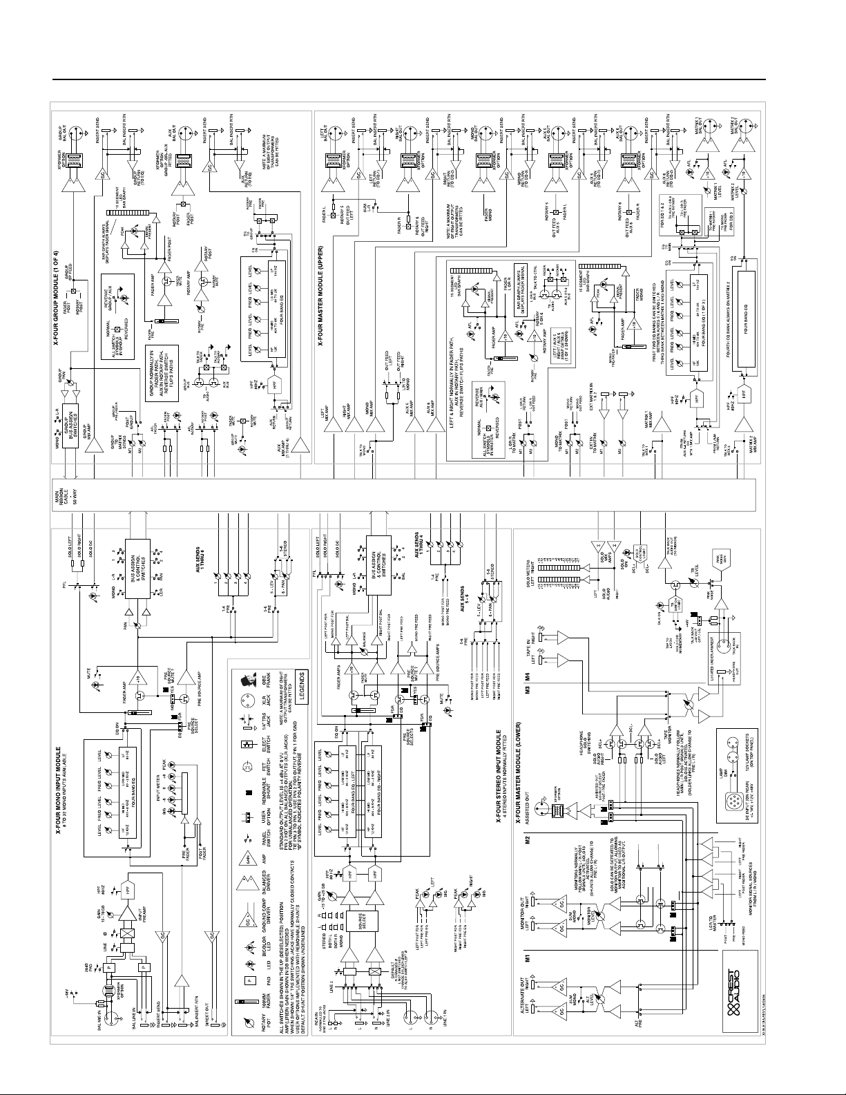
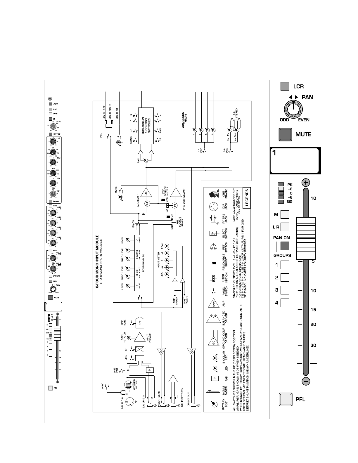
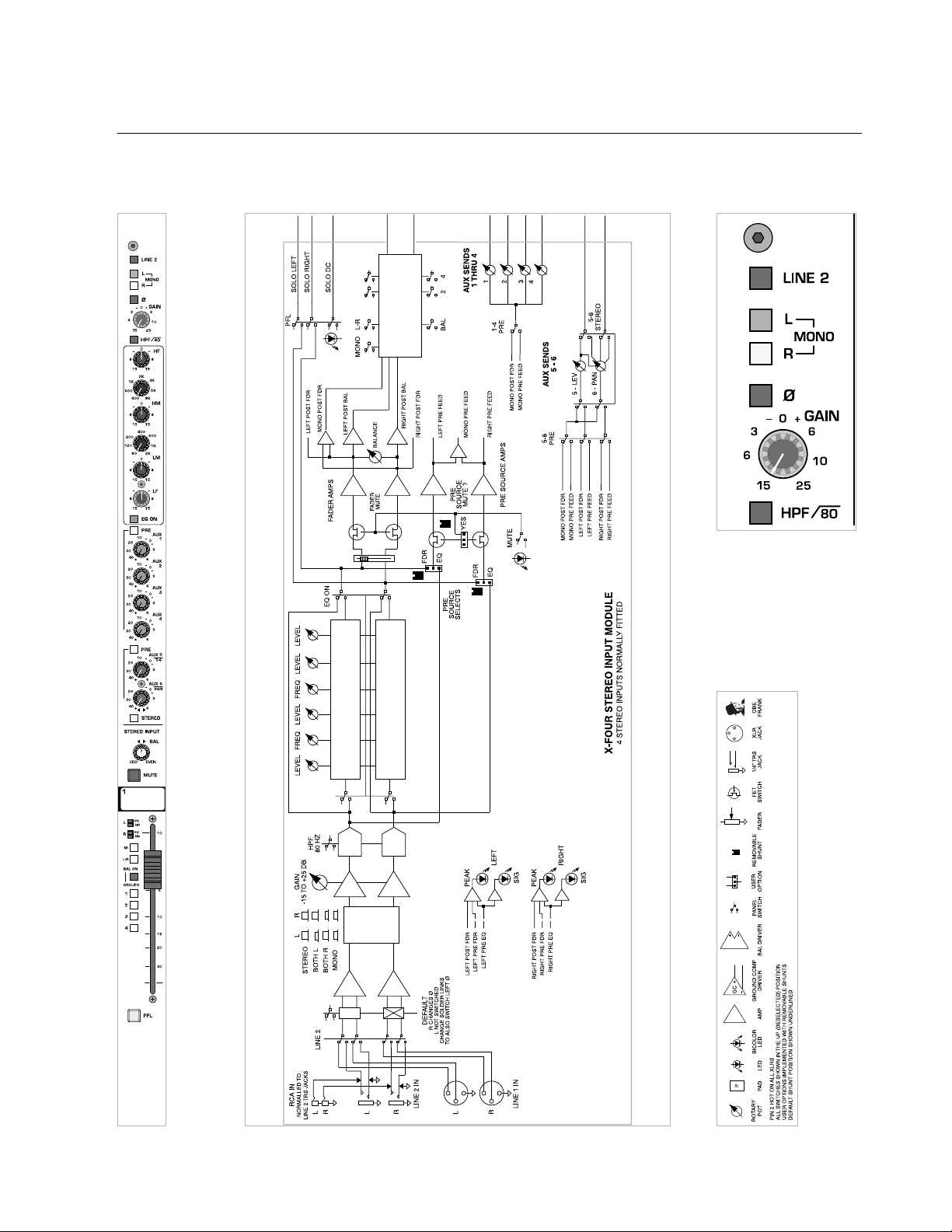
block diagram
Σ
OFF
Ø
R
L
1 3
SOLO
OFF
SOLO
AUDIO
ON
MONITOR OUT
SOURCE SELECT
POST / PRE FADER
LR
LR
FROM
SOLO
LOGIC
SCL+
HP
LEVEL
X-Four Block Diagram
SCL-
+10
+10
PEAK
LO MID
Σ
Σ
Σ
Σ
Σ
Σ
Σ
Σ
NO
+10
L
R
2
4
4
1
3
Page 3

1
2
3
4
5
group p. 41
master p. 57
power supply p. 81
stereo inputs p. 25
mono inputs p. 7
table of contents
Page 4

X-Four owner’s manual
Page 5

how to use this manual
conventions
terms
indicators or controls employed on the X-Four console
will appear as:
TERMS
tasks
are broken down into steps
1
2
3
warnings
indicators
tips
see
see—references other sections of the manual containing
supplementary information on the current topic or a related issue
Prefered methods.
Helpful hints.
Feature insights.
+
Procedures not to attempt.
Issues or hazards to keep
in mind when operating
the equipment.
a
What to look
for on-screen.
Alerts, indicators, or
prompts that may appear.
®
Page 6
p. 6
X-Four owner’s manual
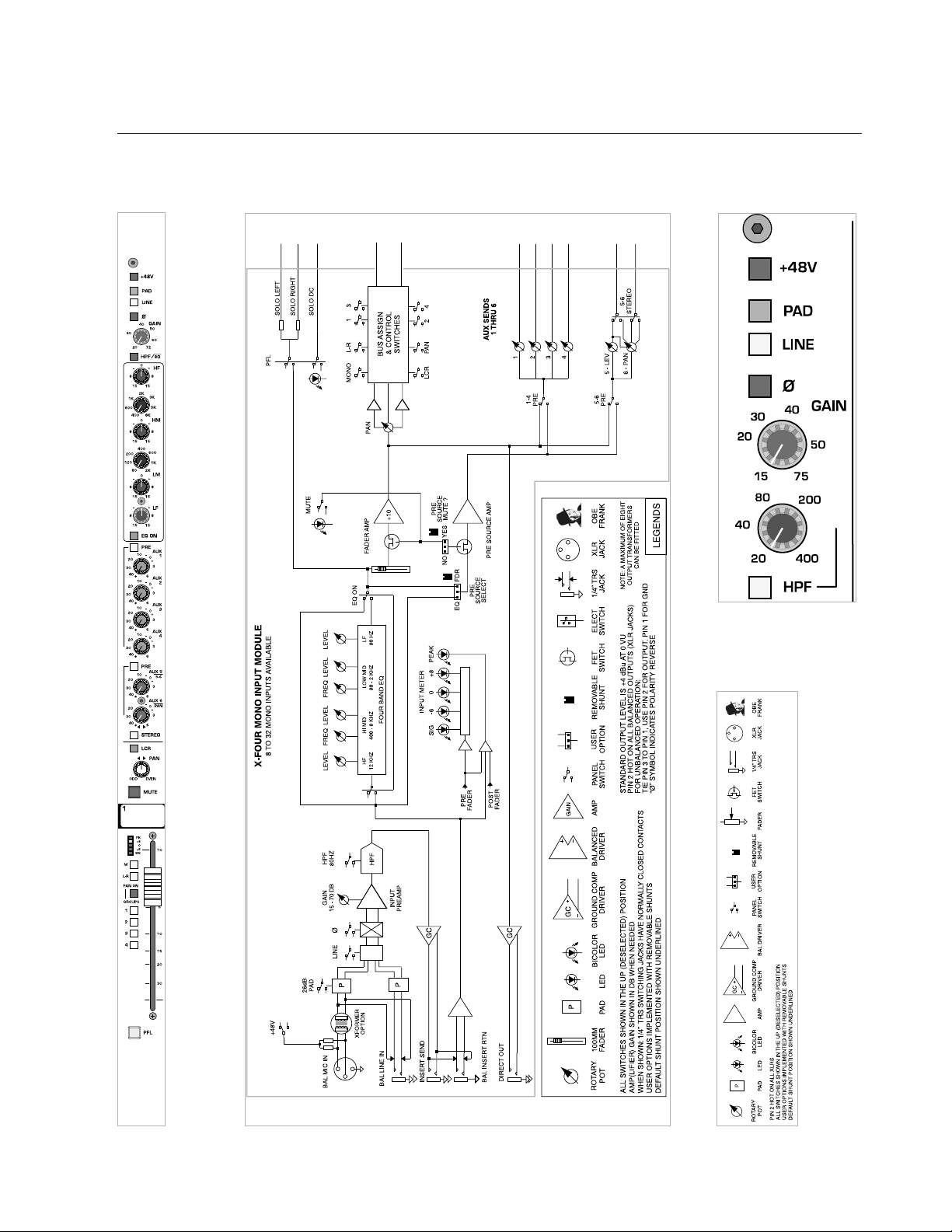
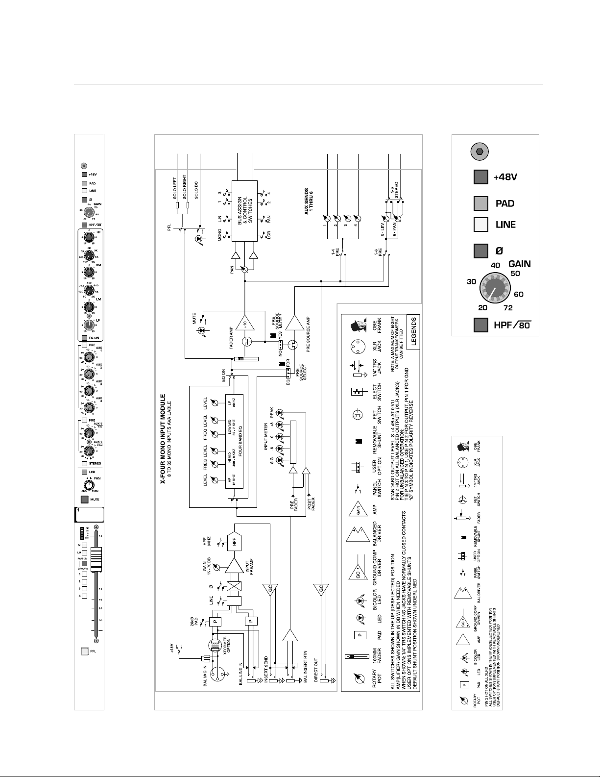
mono input module
module
panel
legend
block diagram
1
Page 7
p. 7
mono input module
features
phantom power—+48V
48 volts DC is applied to pins 2 and 3 on the mic-input XLR connector. This option is used with condenser microphones and active direct
boxes that require an external DC voltage (phantom power) in order to
operate.
pad
The mic-input signal is attenuated by 15dB to prevent some signals
(e.g. kick drum or lead vocal) from overloading the preamp stage.The pad
is used to bring a hot mic-input signal down to a controllable level.The
15dB pad is not functional when the
LINE switch is depressed.
line
The input preamp circuit is set up to accept a mic-level signal. This
signal is brought in via the XLR mic-input connector located on the rear
panel.The 1/4" TRS input jack is disabled.
The input preamp circuit is set up to accept a line-level signal from
either the XLR mic-input connector or the 1/4" TRS input jack, both located on the rear panel.
When a plug is inserted into the 1/4" TRS input jack, the XLR mic-input
connector is disabled.
polarity reverse—ø
This feature is used for correcting or minimizing polarity and phase related errors. For example, occasionally a balanced input connection is
reverse-wired before it gets to the mixing console. This can happen in
microphones, or in snake line interfaces. By using the polarity reverse feature, this type of error can be corrected.
polarity inverted
polarity not inverted
If the channel peak
LED is illuminated,
first try lowering
the input gain control.
Only when this method is
unsuccessful should the pad
switch be engaged.
+
If the 48V phantom
power switch is
engaged, depressing this
switch disconnects phantom
power from the mic input
XLR.
+
1
When similar signals
from different channels are combined, phase
cancellations can occur.
Reversing the polarity of an
input signal often corrects
such phasing errors.
+
The 48V switch should
not be engaged when
using standard (dynamic)
microphones, or other
sources that do not use
phantom power.
a
Page 8
p. 8
X-Four owner’s manual
mono input module
module
panel
legend
block diagram
1
Page 9
p. 9
mono input module
features
gain
The Input gain control range is closely related to the status of the
PAD
switch and the LINE switch. In order to establish proper gain structure in
the console, input gain settings must be set correctly.
LINE—switch-up PA D —switch-up
15 to 75dB of gain can be added the mic-input signal.
The impedance at the input XLR is 4kΩ.
LINE—switch-up PA D —switch-down
-5 to 55dB of gain can be added to the mic-input signal.
The impedance at the input XLR is 4kΩ.
LINE—switch-down PA D —switch-up or -down
-10 to 45dB of gain can be added the line-input signal.
The impedance at the input XLR and input 1/4" TRS is 20kΩ.
high-pass filter—HPF
Proper use of the high-pass filter reduces or eliminates unwanted low frequencies without substantially affecting the program material. Quite often
such unwanted low frequencies are included with in-coming mic- or lineinput signals. For example, stage rumble or wind can be picked up through
vocal mics.The slope of the high-pass filter is 12dB per octave.
HPF
High-pass filter is on @ 80 Hz, 12 dB/octave
1
If the channel peak
LED is illuminated,
first try lowering
the input gain control.
Only when this method is
unsuccessful should the pad
switch be engaged.
+
Page 10
1
p. 10
X-Four owner’s manual
mono input module
module
legend
block diagram
panel
Page 11

p. 11
mono input module
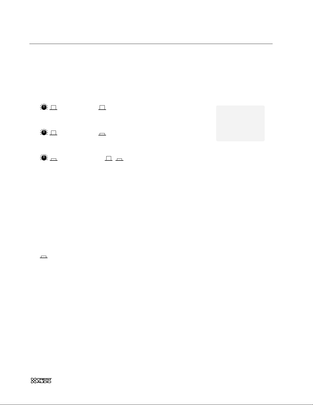
EQ features
Many audio signals coming into the console require some degree of corrective eq in order to be part of a good sounding mix.
The input eq consists of four-bands: high, high-mid, low-mid and low.
The high and low bands have fixed frequencies while the high-mid and lowmid bands are sweepable, with their higher and lower frequencies overlapping adjacent bands.
high frequency—HF
15dB boost and cut at 12kHz.
The boost response is bell-shaped and the cut response is shelving.
high-mid frequency—HM
15dB boost and cut.
Selectable frequency range of 400Hz to 8 kHz.
The response is bell shaped with a fixed Q of 1.5
low-mid frequency—LM
15dB boost and cut
Selectable frequency range of 80Hz to 2 kHz.
The response is bell shaped with a fixed Q of 1.5
low frequency—LF
15dB boost and cut at 80Hz.
The boost response is bell-shaped and the cut response is shelving.
eq on
Equalizer is on. This switch can be used to make A/B comparisons
between "flat" and eq'd signals.
1
Page 12

1
p. 12
X-Four owner’s manual
mono input module
module
panel
block diagram
Page 13

p. 13
mono input module
aux send features
Six auxiliary AUX SENDS
are available for creating individual output mixes.
These mixes can be used for driving effects processors, providing monitor
mixes, creating broadcast or alternate sound reinforcement mixes, or
other special requirements.
aux sends 1–6
These knobs adjust the amount of signal sent to the AUX buses.
Unity gain occurs at the zero setting.
AUX 6 and 8 controls pan function
when selected for stereo operation.
aux 1–4, 5/6 pre-fader—PRE
The default signal source for the AUX SENDS is post-fader. These switches
are used for selecting the pre-fader signal for their respective auxes.The
pre-fader signal is derived post-mute and post-eq.
see—internal jumper options
AUX SENDS
are post-eq, post-mute, and post-fader.
AUX SENDS
are post-eq, post-mute, and pre-fader.
aux stereo 5/6
The default configuration for AUX
5, and 6, are mono, as with AUX 1–4.
In situations where stereo-aux signals are required (such as driving stereo
in-ear monitors or effects processors), this switch reconfigures the
AUX
SENDS
to operate in stereo by changing the functions of the potentiometers.
AUXES
are configured as individual mono sends.
AUXES are configured as level and pan for stereo operation.
1
Page 14

1
p. 14
X-Four owner’s manual
mono input module
module
panel
block diagram
Page 15

p. 15
mono input module
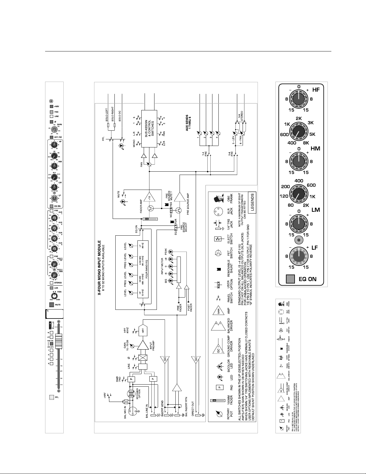
bus assignment features
The Input bus assignment section offers considerable flexibility for creating what eventually becomes the main output mix. Such features as
LCR,
GROUP PAN ON
and eight-individual group assignments allow several
approaches to building the desired mix.All assignments are derived postfader, post-eq,and post-mute.
left-center-right—LCR
This feature is used to precisely position a signal in a sound system with a
center speaker cluster in addition to left and right clusters.The
PAN control
becomes an integral part of how the input-signal is sent to the
LEFT, CEN-
TER, and RIGHT outputs.
The post-fader signal is assigned to the
LEFT
, RIGHT, and MONO/CENTER
buses. Relative amounts of the signal fed to each bus is determined by the
position of the
PAN control.
pan control
The pan control positions the signal within the stereo left/right field,
(or between left/center or center/right in
LCR mode).The signal must be
assigned as stereo in order for the pan control to have any affect.
see—left-center-right
mute
The Mute switch mutes the channel as well as both pre- and post-
fader
AUX SENDS.
write-in label
This label may be written on with a grease-marker, and later wiped clean
with a cloth moistened with isopropyl/rubbing alcohol. Masking tape may
also be placed on this surface, if desired.
1
An internal jumper
can be used to defeat
pre-fader muting.
+
Page 16
1
p. 16
X-Four owner’s manual
mono input module
module
panel
block diagram
Page 17

p. 17
mono input module
bus assignment features
mute
The Mute switch mutes the channel as well as both pre- and post-
fader
AUX SENDS
.
write-in label
This label may be written on with a grease-marker, and later wiped clean
with a cloth moistened with isopropyl/rubbing alcohol. Masking tape may
also be placed on this surface, if desired.
1
Page 18

1
p. 18
X-Four owner’s manual
mono input module
module
panel
block diagram
Page 19

p. 19
mono input module
level meter features
level meter
Each input includes a five-segment
LED meter
for visually monitoring signal levels.This is essential for setting up and maintaining proper gain structure.
peak indicator—PK
The input signal is monitored at several points throughout the channel.These points are the mic preamp, the EQ stage and the fader stage.
Overloads at any of these stages will cause the red peak-
LED to light.
Then the channel gain should reduced.
signal level LED’s
These three LED's light up at +8—yellow, 0—green, and -6 dB—
green. This level range -6 to +8 is the optimum operating range.
Compressed or relatively constant signals should remain close to 0.
signal present indicator—SIG
This green-LED varies in brightness in response to signal levels
between -40 dB and -6 dB.
LED
LED
LED
LED
LED
LED
LED
LED
Occasional flashing of the
peak LED is acceptable,
but frequent flashes indicate that channel levels
must be lowered.
®
1
If the channel peak
LED is illuminated,
first try lowering
the input gain control.
Only when this method is
unsuccessful should the pad
switch be engaged.
+
Page 20
1
p. 20
X-Four owner’s manual
mono input module
module
panel
block diagram
Page 21
p. 21
mono input module
bus assignment features
mono assignment—M
The signal is assigned to the discrete mono bus.
When the
LCR button is depressed, this switch is bypassed.
left / right assignment—L-R
The Group signal is assigned to the main Left and Right output buses,
deriving its signal after the channels pan system.When the LCR button is
depressed, this switch is bypassed.
pan on—groups—BAL ON
The four GROUP assignment switches assign the input signal in mono,
independent of the pan pot.
The four
GROUP assignment switches assign signals as four stereo-
pairs.The
PAN
control governs the stereo placement of the four stereo-
pairs, which are now configured as odd–left / even–right.
For example:
GROUP 1—left,GROUP 2—right, GROUP 3—left,GROUP 4—right.
group 1–4 assignment
The input channel's post-fader signal is assigned to the corresponding
GROUP bus(es).
see—pan on—groups
input fader
The input fader is the primary level control for signals being sent to any of
the console's mix buses.The only signals not affected are
AUX sends select-
ed to be pre-fader. The fader offers greater than 80db of attenuation and
up to 10db of boost. Normal operation is between -10 and 0.
pre-fader listen—
PFL
Pressing this switch will include (illuminated) or exclude (not-illuminated) the input channel.
see—master module
Always turn off and
disconnect the amplifier from mains voltage
before making audio
connections.
As an extra precaution, have
the attenuators turned down
during power-up.
+
1
Page 22
1
p. 22
X-Four owner’s manual
mono input module
module
panel
block diagram
Page 23
p. 23
mono input module
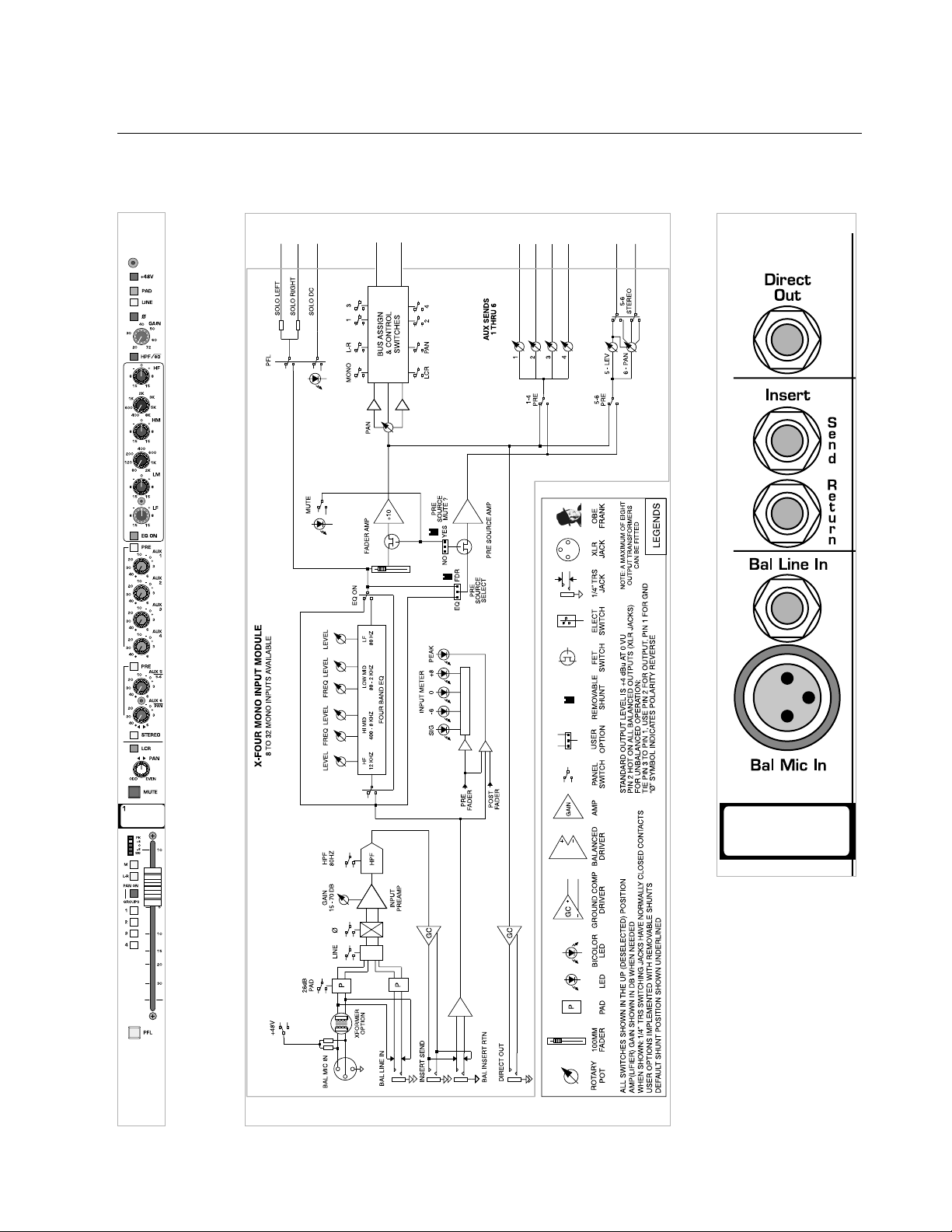
rear panel features
direct out
1/4" TRS jack
The input channel's signal is available at this output jack.The
default signal routing is derived post-fader, post-eq and post-mute.This
output jack is ground-compensated.
insert points
Separate 1/4" TRS jacks provide the facilities for inserting an external signal processor into the signal path of the input channel.
insert send
This jack serves as an output for connection to the input of a
signal processor. The signal is derived after the mic preamp and
HPF but
before the eq section.Plugging a
1/4" TRS plug into this jack does not break
the signal flow of the channel.This output jack is ground-compensated.
insert return
The output of a signal processor is fed to this jack.It can accept
a balanced or unbalanced signal and is located pre-eq.
balanced line-in jack—Bal Line In
Line-level signals, balanced or unbalanced, may be brought into
the input channel through this jack.The
LINE
switch must be depressed for
this jack to be active.
balanced mic-in xlr connector—Bal Mic In
This balanced female XLR accepts a low-impedance microphone
signal, or a line-level signal, depending on position of the
LINE switch on
the front panel.
see—mono input module, phantom power, line
F
In situations where
the preamp circuitry is
not needed, the Insert
Return can be used as the
channel’s input.
For example, when using an
expensive tube mic preamp.
+
The insert send can
also be used as an
additional channel output
when s pre-EQ signal is
needed.
+
1
Page 24
p. 24
X-Four owner’s manual
stereo input module
module
panel
legend
block diagram
Ø
R
L
1 3
+10
L
R
NO
2
Page 25
p. 25
stereo input module
features
The stereo input module can be configured to operate as either stereo or
mono.When configured to operate in mono, many features are identical
to those of the mono input module.
line select—Line 2
This switch determines selection of input signals from the three sets of
rear panel connectors.
The channel is in LINE 1 MODE. The signals are brought in via the left
and right line-input
XLRs located on the rear panel.
The channel is in
LINE 2 MODE.The signals are brought in via the RCA
line-input connectors which are normalled through the 1/4" TRS line-input
jacks. Insertion of a plug into the
1/4"
jack disconnects the RCA jacks.
left and right mono-switches
These switches provide several options for configuring the stereo lineinput module as a mono line-input module.
left right
Signals brought into the left and right inputs are treated as stereo
throughout the module.
left right
Signals brought into the left and right inputs are summed together immediately before the
GAIN control.The summed signal is treated as mono
throughout the rest of the module.
left right
The signal fed to the left input is treated as a mono signal throughout the
module. No signal from the right input is used.
left right
The signal fed to the right input is treated as a mono signal throughout
the module. No signal from the left input is used.
2
To avoid redundancy,
mono features will refer
back to corresponding sections on the Mono module.
Descriptions given here are
specifically for the default
Stereo configuration.
+
Page 26

p. 26
X-Four owner’s manual
stereo input module
module
panel
legend
block diagram
Ø
R
L
1 3
+10
L
R
NO
2
Page 27

p. 27
stereo input module
features
input gain—GAIN
This control adjust the gain of the input preamp(s).
Both left and right input signals are affected by this control.
polarity reverse—ø
This switch inverts the polarity of the right input signal in relation to the
left input signal.
see—mono input module
Polarity of the right input signal is inverted.
Polarity of the right input signal is not inverted.
high-pass filter—
HPF
The high-pass filter is activated for signals coming into both the left and
right inputs.The shelving frequency is fixed at 80Hz with a slope of 12dB
per octave.
Proper use of the high-pass filter reduces or eliminates unwanted low frequencies, without substantially affecting the program material. Quite often
such unwanted low frequencies are included with in-coming mic- or lineinput signals. For example, stage-rumble or wind can be picked up through
vocal mics.
2
Page 28

2
p. 28
X-Four owner’s manual
stereo input module
module
panel
legend
block diagram
Ø
R
L
1 3
+10
L
R
NO
Page 29

p. 29
stereo input module
four-band stereo EQ features
Although left and right signals are processed separately, the parameters are
set in tandem by common front-panel controls.
see—mono input module
high frequency—HF
15dB boost and cut at 12kHz—shelving response.
high-mid frequency—HM
15dB boost and cut.
Selectable frequency range of 400Hz to 8 kHz.
The response is bell-shaped with a fixed Q of 1.5
low-mid frequency—LM
15dB boost and cut.
Selectable frequency range of 80Hz to 2kHz.
The response is bell-shaped with a fixed Q of 1.5
low frequency—LF
15dB boost and cut at 80Hz.
The boost response is bell-shaped and the cut response is shelving.
equalizer—EQ ON
Equalizer is on.This switch can be used to make A/B comparisons
between "flat" and eq'd signals.
2
Page 30

2
p. 30
X-Four owner’s manual
stereo input module
module
panel
block diagram
Ø
R
L
1 3
+10
L
R
NO
Page 31

p. 31
stereo input module
aux send features
The following descriptions apply to the stereo line input module when
configured for stereo operation.
see—mono input module for mono operation
aux send 1–6 controls
These knobs adjust the amount of signal sent the
AUX buses.
AUX 1–4 are fed from a summed-mono source. AUXES 5–6 are also fed
from this mono source, but can be switched to stereo operation.
see—stereo balance
aux 1-4, 5/6 pre-fader—PRE
The default signal source for the AUX SENDS is post-fader. These switches
select a pre-fader source for their respective auxes.The pre-fader signal is
derived post-mute and post-eq.
see—internal jumper options
Corresponding AUX SENDS are post-eq, post-mute and post-fader.
Corresponding
AUX SENDS are post-eq, post-mute and pre-fader.
stereo balance 5 and 6—
STEREO
AUX 5 and 6 are mono.
AUX 5 acts as a left and right level-control and AUX 6 acts as a left/right
balance-control.
2
Page 32

2
p. 32
X-Four owner’s manual
stereo input module
module
panel
block diagram
Ø
R
L
1 3
+10
L
R
NO
Page 33

p. 33
stereo input module
bus assignment features
balance control
The Balance control adjusts the Stereo balance for Left/Right and the
Group Assignment section when in Balance mode.
When the Stereo Line Input module is being used as a Mono input, the
Balance control functions as a Pan control.
mute
see—mono input module for full description
write-in label
This label may be written on with a grease-marker, and later wiped clean
with a cloth moistened with isopropyl/rubbing alcohol.
2
Page 34

2
p. 34
X-Four owner’s manual
stereo input module
module
panel
block diagram
Ø
R
L
1 3
+10
L
R
NO
Page 35

p. 35
stereo input module
bus assignment features
peak indicator—PK
The input signal is monitored at several points throughout the channel.These points are the mic preamp, the EQ stage and the fader stage.
Overloads at any of these stages will cause the red peak-
LED
to light.
Then the channel gain should reduced.
signal level LED’s
These three LED's light up at +8—yellow, 0—green, and -6 dB—
green. This level range -6 to +8 is the optimum operating range.
Compressed or relatively constant signals should remain close to 0.
mono assignment—M
The input signal is assigned to the discrete mono bus. Left and right
signals are summed to make up the mono or center signal.
left/right assignment—
L/R
The stereo input signals are assigned directly to the main left and
right output buses.
The proportion of left vs. right can be adjusted by the
BALANCE control.
LED
LED
Best operation occurs when
the green
LED is brightly
illuminated and the red
LED
occasionally flickers.
®
2
Page 36

2
p. 36
X-Four owner’s manual
stereo input module
module
panel
block diagram
Ø
R
L
1 3
+10
L
R
NO
Page 37

p. 37
stereo input module
bus assignment features
balance on—groups—
BAL ON
The left and right signals are summed as mono to make up the group
assignment signals.
The left and right signals are assigned in stereo to the groups in
odd/even pairs.
GROUP
assignment switches 1 and 3 carry the left input-sig-
nal and
GROUP
assignment switches 2 and 4 carry the right input-signal.
The proportion of left vs. right can be adjusted by the
BALANCE control.
group 1–4 assignment
The input channel's post-fader signal is assigned to the corresponding
GROUP bus(es).
see—balance on—groups
input fader
The input fader is the primary level control for signals being sent to any of
the console's mix buses.The only signals not affected are
AUX sends select-
ed to be pre-fader. The fader offers greater than 80db of attenuation and
up to 10db of boost. Normal operation is between -10 and 0.
pre-fader listen—PFL
Pressing this switch will include (illuminated) or exclude (not-illuminated) the input channel.
see—master module
2
Page 38

2
p. 38
X-Four owner’s manual
stereo input module
module
panel
block diagram
Ø
R
L
1 3
+10
L
R
NO
Page 39

p. 39
stereo input module
rear panel features
The stereo line-input module provides connectors for three stereo linelevel signals.
see—line 2 switch.
balanced left and right line-in XLR connectors
These two jacks accept balanced or unbalanced +4dB line level signals.The
LINE
2 switch on front-panel must be disengaged for these connectors to
be active.
line-input left and right
1/4" TRS jacks
These two jacks accept balanced or unbalanced line level signals.The LINE
2
switch on front panel must be engaged for these jacks to be active.
line-input left and right
RCA connectors
These two jacks accept unbalanced line-level signals.They are active when
the
LINE 2 switch on front-panel is engaged and nothing is plugged into the
corresponding left or right
1/4" TRS jack(s).
F
2
Page 40

p. 40
X-Four owner’s manual
group module
module
panel
block diagram
Σ
+10
+10
Σ
3
Page 41

p. 41
group module
output eq features
The X-Four output-section includes eight output-equalizers occupying the
upper portions of the four
GROUP
sub-modules and the four
MASTER sub-
modules.
By using designated assignment switches, output eq’s can be fed by the six
AUXES or GROUPS
, the two matrix masters or left, right, and mono masters.
Each eq features four bands of equalization,making them ideal for feeding
on-stage or in-ear monitors.
high frequency—HF
15dB boost and cut at 12kHz—shelving response.
high-mid frequency—HM
15dB boost and cut.
Selectable frequency range of 400Hz to 8 kHz.
The response is bell-shaped with a fixed Q of 1.5
mid frequency—MID
15dB boost and cut
Selectable frequency range of 200Hz to 4kHz.
The response is bell-shaped with a fixed Q of 1.5
low-mid frequency—LM
15dB boost and cut.
Selectable frequency range of 80Hz to 2kHz.
The response is bell-shaped with a fixed Q of 1.5
low frequency—LF
15dB boost and cut at 80Hz.
The boost response is bell-shaped and the cut response is shelving.
3
Page 42

p. 42
X-Four owner’s manual
group module
module
panel
block diagram
Σ
+10
+10
Σ
3
Page 43

p. 43
group module
output EQ features
equalizer—EQ ON
Equalizer is on.This switch can be used to make A/B comparisons
between "flat" and eq'd signals.
group equalization —per output channel—EQ TO GROUP
This switch selects the signal path for the eq.
eq to
AUX MASTERS
eq to GROUPS
This switch can be
used to make A/B
comparisons of "flat"
and EQ'd signals.
+
3
Page 44

p. 44
X-Four owner’s manual
group module
module
panel
block diagram
Σ
+10
+10
Σ
3
legend
Page 45

p. 45
group module
matrix features
The X-Four includes two MATRIX
outputs. Each of these outputs can be
made up of signals from the four
GROUPS
; the left, right and mono buses;
and an external source.
matrix 1–2 levels—M1, M2
These level controls are used to mix the group's signal into the cor-
responding matrix.
post-group
The GROUP fader setting has no effect on the group-to-matrix level
controls 1–2.
The
GROUP fader is introduced into the signal path.When the group
is muted, the matrix level controls 1–2 are muted as well.
3
Page 46

p. 46
X-Four owner’s manual
group module
module
panel
block diagram
Σ
+10
+10
Σ
3
legend
Page 47

p. 47
group module
fader reverse
The AUX /
GRP feature is used to swap the functions of the
AUX MASTER con-
trols and the
GROUP MASTER
controls and the
AUX MASTER and LEFT/RIGHT
MAIN
controls.
Swapped controls include: the
TALK TO
switch, the SOLO switch, the
MUTE
switch, and the MASTER LEVEL
control (via rotary control on the
AUX MASTER
and a fader on the GROUP MASTER
).
reversing aux / group and aux / main
AUX—red LED off
The
AUX 1– 6 and GROUP 1– 4 MASTER and LEFT/RIGHT MAIN level controls,
SOLO, MUTE and TALK TO switches operate as normal in their default con-
figuration.
GRP—red
LED
on
AUX and GROUP functions are reversed.
The
AUX 1– 6 output levels are controlled by the output faders.
The
AUX SAFE PREVIEW LED, AUX SOLO, and AUX TALK TO switches apply to
the
GROUP output signal.
The
GROUP 1– 4 and LEFT/RIGHT MAIN output levels are controlled by the
rotary
AUX 1– 6 MASTER level controls.
The
GROUP SOLO, GROUP MUTE and GROUP TALK TO switches apply to the
AUX
output signal.
aux 1–6 output level
The AUX MASTER output level controls set the levels that appear at the
corresponding
AUX output connectors on the rear-panel.
talk to—aux 1–6
Adds the TALKBACK system output to the associated AUX output.The
level of the
TALKBACK signal is set by the TALKBACK level control in the MAS-
TER section.
after-fader listen—
AFL
Pressing this switch will include the AUX (when illuminated) or
exclude (when not illuminated).
see—master module
LED
3
Page 48

p. 48
X-Four owner’s manual
group module
module
panel
block diagram
Σ
+10
+10
Σ
3
legend
Page 49

p. 49
group module
group assignment features
mono assignment—from group—
MONO
The GROUP signal is assigned to the discrete mono bus.
left/right assignment—from group—
L/R
The
GROUP signal is assigned to the main left and right output buses.
pan
The PAN pot is used to position the group signal within the stereo left
/ right field.The signal must be assigned to left and right in order for the
PAN
control to have any effect.
mute
see—mono input module for full description
This is a useful feature when the mixer is
being used to feed on-stage
or in-ear monitors.
A red LED visually indicates
when this feature has been
selected.
There is one switch for each
of the six AUX MASTERS /
GROUP MASTERS
.
+
3
Page 50

p. 50
X-Four owner’s manual
group module
module
panel
block diagram
Σ
+10
+10
Σ
3
Page 51

p. 51
group module
group/aux level features
signal/peak LED
’s
This dual color
LED responds to the pre-fader signal. It illuminates
green with varying brightness in proportion to the audio signal.When the
signal approaches clipping, the
LED illuminates red.
talk to—fader 1–4
This switch adds the
TALKBACK system output to the fader signal.The
level of the
TALKBACK signal is set by the TALKBACK level control in the MAS-
TER section.
fader
The fader normally controls the level at which the
GROUP signal is sent to
any assigned buses or outputs. When the
REVERSE AUX/GROUP switch is
selected, the fader controls the level of the
AUX output.
after-fader listen—AFL
Pressing this switch will include or exclude the fader signal (when not
illuminated).
LED
3
Page 52

p. 52
X-Four owner’s manual
group module
module
panel
block diagram
Σ
+10
+10
Σ
3
Page 53

p. 53
group module
rear panel features
group output
This balanced male XLR connector carries the
GROUP output signal.
see—group fader, front-panel description
group insert point
Separate 1/4" TRS jacks provide the ability to insert an external signal
processor into the signal path of the
GROUP.
group insert send
This output connects to the input of an external signal proces-
sor. The signal is derived after the group-summing amplifier.
This output is ground compensated.
group insert return
This balanced input accepts a signal from the output of an
external signal processor. It accepts either balanced or unbalanced signals.
M
Plugging a 1/4" plug
into this jack does not
break the internal signal
flow of the Group.
+
Plugging a 1/4" plug
into this jack breaks
the signal flow
of the Group.
+
3
Page 54

p. 54
X-Four owner’s manual
group module
module
panel
lamp dim switch and
DC IN connector
block diagram
Σ
+10
+10
Σ
3
Page 55

p. 55
group module
rear panel features
auxiliary 1– 6 output XLR’s
This balanced male
XLR connector carries the AUX output signal.
These outputs are controlled by their respective
AUX output level controls.
see—aux section, front panel description
aux insert point
Separate
1/4" TRS jacks provide the ability to insert an external
signal processor into the signal path of the
AUX.
aux insert send
This output connects to the input of an external signal proces-
sor. The signal is derived after the group-summing amplifier.
This output is ground-compensated.
group inputs 1–4
These 1/4" TRS
jacks accept balanced or unbalanced line-level signals.
They act as external inputs for
GROUPS 1– 4.
lamp dim
Goose-neck lamps light-up at full intensity.
Goose-neck lamps light-up at medium intensity.
M
3
Plugging a 1/4" plug
into this jack does not
break the internal signal
flow of the Group.
+
Page 56

panel
block diagram
p. 56
X-Four owner’s manual
master module
module
5
Σ
Σ
Σ
PEAK
Σ
Σ
LO MID
Σ
Σ
Page 57

p. 57
master module
output EQ features
On the MASTER module block, the default sources for the four output eq’s
are the
AUX
5 and 6,
and MATRIX 1 and 2.
By using designated assignment switches, source for the first three output
eq’s can be switched over to the left,right and mono masters.The fourth
eq is always fed by
MATRIX
2 master.
All eq's feature four bands of equalization.
see—group module
high frequency—HF
boost / cut -15 dB boost and cut at 12kHz—shelving response.
high-mid frequency—HM
boost / cut - 15 dB boost and cut.
selectable frequency range of 400Hz to 8 kHz.
The response is bell-shaped with a fixed Q of 1.5.
low-mid frequency—LM
boost / cut - 15 dB boost and cut
selectable frequency range of 80Hz to 2 kHz.
The response is bell-shaped with a fixed Q of 1.5.
low frequency—LF
boost / cut 15 dB boost and cut @ 80Hz.
5
Page 58

panel
block diagram
p. 58
X-Four owner’s manual
master module
module
5
Σ
Σ
Σ
PEAK
Σ
Σ
LO MID
Σ
Σ
Page 59

p. 59
master module
output EQ features
equalizer—EQ ON
Equalizer is on. This switch can be used to make A/B comparisons
between flat and eq’d signals.
left, right, mono equalization—EQ TO LEFT, TO RIGHT, TO MONO
These three switches select the signals fed to each of the first three
eq’s on the first three master sub-modules.The fourth
MASTER sub-module
does not include a switch because its source is always
MATRIX 2.
AUX 5 and 6 are fed to the first two eq’s.
MATRIX
1 is fed to the third eq.
left, right and/or mono are fed to the first three eq’s.
5
Page 60

panel
block diagram
PEAK
LO MID
Σ
Σ
Σ
Σ
Σ
Σ
Σ
p. 60
X-Four owner’s manual
master module
module
5
Page 61

p. 61
master module
matrix features
The X-Four includes two MATRIX
mixes.Each of these outputs can be made
up of signals from the four
GROUPS
, left, right,mono and an external source.
left, right, and mono levels—MATRIX
1–2
These level controls are used to mix the left, right, and mono signals
into the corresponding
MATRIX.
post-fader—left, right, and mono
These three post-fader switches determine whether the left, right and
mono
MASTER faders have any effect on signals that available to MATRIX 1–2.
post-left, post-right, post-mono
The left, right and/or mono fader settings have no effect on the LEFT-,
RIGHT- and/or MONO-TO-MATRIX 1–2 level controls.
The left, right and/or mono faders are introduced into the signal
paths.
external input levels—MATRIX 1–2
These level controls are used to mix the external MATRIX input signals
into the corresponding matrix.The external
MATRIX input connectors are
located on the rear-panel of the
MASTER module.
5
Page 62

p. 62
X-Four owner’s manual
master module
module
5
block diagram
PEAK
LO MID
Σ
Σ
Σ
Σ
Σ
Σ
Σ
panel
Page 63

p. 63
master module
matrix output features
master output levels—MTX 1–2
These are the
MASTER output level controls for the MATRIX
section.
They control the levels that appear at the corresponding
MATRIX
output
connectors on the rear-panel.
matrix 1–2 talkback—TALK TO
This switch adds the TALKBACK system output to the MATRIX outputs.
The level of the
TALKBACK signal is set by the TALKBACK level control in the
MASTER section.
after-fader listen—AFL
Pressing this switch will include (illuminated) or exclude (not ilumi-
nated)
MATRIX.
see—master module
5
Page 64

panel
block diagram
p. 64
X-Four owner’s manual
master module
module
5
Σ
Σ
Σ
PEAK
Σ
Σ
LO MID
Σ
Σ
Page 65

p. 65
master module
alternate out features
The ALTERNATE
output section allows assignment of the left and right MASTER
signals (plus center—if LCR-TO
-OUTPUTS
is selected) to a separate pair of bal-
anced male XLR connectors on the rear-panel.
By utilizing the mode switches located below the
ALT OUT
level control,these
signals can be derived in a number of ways. In default mode (no switches
depressed), the post-fader left and right
MASTER
(in center) signals are rout-
ed through the
ALT OUT
level control and appear at the
ALT OUT connectors.
alternate out level
This control sets the levels that appear at the ALT OUT left and right
balanced
XLR connectors on the rear-panel.
sum mono
The main left and right (and mono/center) signals are summed
together as a mono signal.This signal is then routed through the
ALT OUT
level control and appears at the left and right ALT OUT balanced male XLR
connectors on the rear-panel.
The main left and right (and mono/center) signals are routed in
stereo through the
ALT OUT Level control and appear at the left and right
ALT OUT balanced male XLR connectors on the rear-panel.
pre switch
The left and right (and mono/center) master faders have no effect on
the left and right (and mono/center) signals routed through the
ALT OUT
level control and appear at the left and right ALT OUT balanced male XLR
connectors on the rear-panel.
The left and right (and mono/center) master faders control the lev-
els of the left and right (and mono/center) signals routed through the
ALT
OUT
level control and appear at the left and right ALT OUT balanced male
XLR connectors on the rear-panel.
5
Page 66

p. 66
X-Four owner’s manual
master module
module
5
block diagram
PEAK
LO MID
Σ
Σ
Σ
Σ
Σ
Σ
Σ
panel
Page 67

p. 67
master module
monitor output features
The MONITOR output section controls the audio feed for the console oper-
ator. Features are similar to those of
ALT OUT
section, except that the MON-
ITOR section is normally used to access the
SOLO system as well as main
outputs.
Like the alternate output section, it provides the ability to assign the left
and right
MASTER signals to a designated pair of balanced male XLR con-
nectors on the rear-panel.
By utilizing the mode switches located below the
LOCAL MONITOR OUTPUT
level control, these signals can be derived in a number of different ways. In
default mode (no switches depressed),the post-fader left and right
MASTER
signals are routed through LOCAL MONITOR level control and appear at the
MONITOR OUT
balanced male XLR connectors on the rear-panel.
This feed is replaced by the
SOLO signal when a SOLO is activated on the
console.
monitor-out level
see—alternate out
sum mono
see—alternate out
solo-off
When any of the AFL/PFL switches on the console are active, the
AFL/ PFL audio is routed in stereo through the MONITOR OUT level control
and appears at the left and right
MONITOR OUT balanced male XLR con-
nector on the rear-panel.
This setting overrides the left and right feed to the
MONITOR output.
When any of the
AFL/ PFL switches on the console are active, the
MONITOR outputs are not affected.
headphone level
This control governs the level at the headphone jack located in the
front of the console under the arm rest.
5
Page 68

p. 68
X-Four owner’s manual
master module
module
5
block diagram
OFF
LR
LR
X-Four Block Diagram
panel
Page 69

p. 69
master module
left master features
signal/peak LED—SIG/PEAK
This dual-color
LED responds to the left pre-fader signal.It illuminates
green with varying brightness in proportion to the audio signal.When the
signal approaches clipping,either pre- or post-fader, the
LED illuminates red.
talkback left/right—TALK TO
The
TALKBACK system output is added to the left and right MASTER
outputs.The level of the TALKBACK signal is set by the TALKBACK level con-
trol in the
MASTER section.
sum left/right—SUM L/R
The main left and right signals are summed together as a mono signal and appear at the left- and right-output balanced male XLR connectors
on the rear-panel.
The Main Left and Right signals appear in stereo at the left- and rightoutput balanced male XLR connectors on the rear-panel.
left master fader
This fader governs the main left output level.
after-fader listen—AFL
When this switch is depressed,the left post-fader signal is sent to the
console solo system.
LED
5
Page 70

p. 70
X-Four owner’s manual
master module
module
5
block diagram
OFF
LR
LR
X-Four Block Diagram
panel
Page 71

right master features
signal/peak LED—SIG/PEAK
This dual-color
LED responds to the right pre-fader stereo signal. It
illuminates green with varying brightness in proportion to the audio signal.
When the signal approaches clipping, either pre- or post-fader, the
LED
illuminates red.
right—TALK TO
The TALKBACK system output is added to the left and right MASTER
outputs.The level of the TALKBACK signal is set by the TALKBACK level con-
trol in the
MASTER section.
left/center/right—LCR TO MASTER
This feature is useful for monitoring the console when creating an
LCR
mix. Local monitoring is usually done with one or two speakers.The
LCR
to outputs feature combines the center (or mono) signal with the left and
right signals, creating a phantom center channel.This feature affects the
ALT
OUT
section, the MONITOR OUT
section, the HEARING ASSIST output and the
headphone feed.
Center (mono) channel is not included in the
MONITOR paths.
The center (or mono) channel is combined with left and right
MON-
ITOR
outputs.This makes it possible to hear the center channel without a
designated speaker.
right master fader
This fader governs the main right output level.
after-fader listen—AFL
When this switch is depressed, the right post-fader signal is sent to
the console solo system.
LED
p. 71
master module
5
Page 72

p. 72
X-Four owner’s manual
master module
module
5
block diagram
OFF
LR
LR
X-Four Block Diagram
panel
Page 73

p. 73
master module
mono master features
signal/peak LED—SIG/PEAK
This dual-color LED responds to the pre-fader mono signal.It illuminates green with varying brightness in proportion to the audio signal.
When the signal approaches clipping, either pre- or post-fader, the
LED
illuminates red.
talkback mono—TALK TO MONO
The
TALKBACK
system output is added to the mono MASTER output.
The level of the
TALKBACK signal is set by the TALKBACK level control in the
MASTER section.
main left/ main right—L–R TO MONO
The MAIN left and right post-fader signals are summed together as a
mono signal and are routed to the mono bus.The summed left and right
signals automatically combine with any signals that are assigned directly to
the mono bus to make up the mono output.
The mono output consists exclusively of signals assigned directly to
the mono bus. Signals that appear at the
MAIN
left and right faders do not
appear at the mono output.
mono master fader
This fader governs the mono output level.
after-fader listen—AFL
When this switch is depressed,the mono post-fader signal is sent to
the console solo system.
solo on indicator
This LED will illuminate when the solo system is active.
LED
5
Page 74

p. 74
X-Four owner’s manual
master module
module
panel
OFF
5
block diagram
LR
LR
X-Four Block Diagram
Page 75

p. 75
master module
talkback features
The TALKBACK
system provides facilities for assigning an external signal
(usually the console operator's microphone) to any of the console's outputs. Other signals can be routed through the
TALKBACK
system include the
tone oscillator or the built in
PINK NOISE generator.
talkback level
This control sets the level that appears at any of the outputs with
their respective
TALK TO switches engaged. It also governs the audio level
at the
TALKBACK output XLR connector on the rear panel.
pink noise
The TALKBACK in-connector is disabled and PINK NOISE is sent though
the
TALKBACK
system.
talkback on—TALK ON
This switch must be activated for the
TALKBACK
system to operate.
There are two-ways to activate it:
1 Momentary - Depressing the button for more-than 1/2 of a second will
cause it to act as a momentary switch.When the button is released, the
TALKBACK
section will be shut-off.
2 Toggle - A quick tap on the button (less-than 1/2 second) will cause the
switch to electronically change its state from on-to-off or from off-to-on.
5
Page 76

p. 76
X-Four owner’s manual
master module
module
panel
5
block diagram
PEAK
LO MID
Σ
Σ
Σ
Σ
Σ
Σ
Σ
Page 77

p. 77
master module
rear panel features
left and right alternate output XLR
’s
This pair of balanced male
XLR connectors carries the left and right
ALT OUT
signals.These outputs are controlled by the ALT OUT
level control.
see—left and right alternate output, front-panel description
left and right monitor output jacks
This pair of ground compensated
1/4" TRS
jacks carries the left
and right
MONITOR signals. These outputs are controlled by the MONITOR
level control.
see—monitor, front-panel description
matrix 1–2 output XLR’s
Two balanced male-
XLR
connectors carry the MATRIX 1–2 output sig-
nals.These outputs are controlled by their respective
MATRIX OUTPUT level
controls.
see—matrix, front-panel description
left, right and mono output XLR’s
This group of three balanced male-XLR connectors carries the left,
right and mono output signals.These outputs are controlled by the left,
right and mono output faders.
see—left, right, and mono masters, front-panel description
M
M
M
5
Page 78

block diagram
PEAK
LO MID
Σ
Σ
Σ
Σ
Σ
Σ
Σ
5
p. 78
X-Four owner’s manual
master module
module
panel
Page 79

p. 79
master module
rear panel features
insert points—left, right, and mono
Separate 1/4" TRS jacks provide the ability to insert external signal processor into the signal paths of the left, right and mono
MASTERS.
insert sends—left, right, and mono
These jacks connect to the input of signal processors.The sig-
nals are derived after the left, right and mono summing amplifiers.
insert returns—left, right, and mono
These jacks connect to the outputs of a signal processors.They
can accept balanced or unbalanced signals.
DC
power-in
This jack connects the power supply cable to the console.
5
Plugging a 1/4" plug
into this jack does not
break the internal signal
flow of the respective left,
right, and mono masters.
+
Plugging a 1/4" plug
into this jack breaks
the signal flow
of the respective left, right,
and mono masters.
+
Page 80

p. 80
X-Four owner’s manual
power supply
master rear-panel
model 5A power supply
specifications
+18V @ 5A DC
-18
V @ 5A DC
+12
V @ 4A DC
+48V @ 0.75A DC
two Hirose JR16RK-7S connectors on rear
connector meets
JIS C 5432 standard
grey polyurethane outer jacket, 15 feet long
seven-way, 14-gauge stranded conductors
rated
600 volts, 80 degrees C
UL and CSA approved
Hirose
JR16PK-7S and JR16PK-7P connectors fitted
90 to 250 volts
@ 4.5 amps maximum
universal AC input voltage. No changes needed
0.5 amps idle
IEC 320 C-13 3-pin 15 amp recepticle
removable IEC type
with country-specific mains plug fitted
UL, CSA,and CE
two-
space 19 inch rack mount unit
3.5 inches tall, 17 inches wide, 12 inches deep.
weight:
18 pounds
output power
DC out recepticle
DC out cable
AC mains power supply
AC mains recepticle
cable
approvals
chassis
8
Page 81

p. 81
power supply
power supply usage
supply identification
The type of power supply can be identified by the model number shown
on the back of the chassis and panel label.
power requirements
The X-Four power supplies have certain electrical requirements for proper
operation. If possible the power supply should be connected to a dedicated
circuit.Should any other appliance on the same circuit draw enough current
to overload the circuit,the breaker or fuse will trip causing loss of power to
the console.
The power switch on the supply front panel is also a circuit breaker; there
is no power fuse.Should the supply ever shut down,or trip at start up,simply push the switch to the off position and then push on again.
ground linking
SAFETY CONSIDERATIONS
—each new power supply is shipped with the AC
third-wire ground connected to the console chassis ground.The connection is made at the rear of the power supply unit.This is necessary for safety reasons so that exposed metal parts are grounded. In the event of a live
conductor making contact with the console chassis or the power supply
chassis then the current will flow to ground without a safety hazard arising.
Uninterruptible grounding—in a fixed installation for example,make a connection directly to the console chassis from the safety ground.Disconnect
the ground link on the rear of the power supply.This disconnects console
ground from power supply AC third-wire ground which could possibly
create a hum-loop.
twin-supply operation
When twin-supplies are in use for automatic back-up, then the ground
links on both supplies should be fitted.
In a situation where the safety ground to the console chassis has been connected and the ground path via the power supply is causing a hum-loop,
then disconnect the ground links on both power supplies.
Note the maximum current draw specifications
at left.
Be sure that the circuit to
which you connect the supply can handle the draw.
a
When the console is disconnected from the power
supply the chassis ground
connection to AC third-wire
ground is broken and safety
protection is lost.
a
8
Page 82

p. 82
X-Four owner’s manual
power supply
model 5A power supply
specifications
+18V @ 5A DC
-18
V @ 5A DC
+12
V @ 4A DC
+48V @ 0.75A DC
two Hirose JR16RK-7S connectors on rear
connector meets
JIS C 5432 standard
grey polyurethane outer jacket, 15 feet long
seven-way, 14-gauge stranded conductors
rated
600 volts, 80 degrees C
UL and CSA approved
Hirose
JR16PK-7S and JR16PK-7P connectors fitted
90 to 250 volts
@ 4.5 amps maximum
universal AC input voltage. No changes needed
0.5 amps idle
IEC 320 C-13 3-pin 15 amp recepticle
removable IEC type
with country-specific mains plug fitted
UL, CSA,and CE
two-
space 19 inch rack mount unit
3.5 inches tall, 17 inches wide, 12 inches deep.
weight:
18 pounds
output power
DC out recepticle
DC out cable
AC mains power supply
AC mains recepticle
cable
approvals
chassis
8
master rear-panel
Page 83

p. 83
power supply
power supply usage
console and power supply grounding
Console chassis ground is electrically connected to:the audio ground, pin1 of
XLR connectors, the sleeves of
1/4”
sockets,and to the terminal CON-
SOLE GROUND at the rear of the power supply.
The AC third-wire connection in the power supply cable connects the
metal chassis of the power supply to safety ground.
Rack-mounting—the power supply ground may transfer to the rack case
through the front fixing screws, though this connection is not reliable.
Sound system use—the grounding requirements may call for the ground
link to be disconnected.This is permissible only when an alternative ground
path has been provided.If in doubt seek the advice of an experienced electrical engineer.
redundant power supplies
The console power supply can be considered the single most important
component in an entire sound system.If a power amplifier, a signal processor or a console input goes down in the middle of a show, the show can
still go on. But if the console loses its power supply, the show is over. For
this reason, it is always good practice to incorporate redundant power
supplies for mixing consoles used in professional sound reinforcement
applications.
This should be considered a high priority even when using a very reliable
power supply. In even the most carefully designed sound systems, each
component runs the risk of failure at sometime or another.
Crest Audio uses two methods for attaching redundant power supplies to
consoles. In both methods, the two (or more) power supplies should be
kept on while the console is in use to insure a smooth transition in the
event that one shuts off.
If one power supply drops in voltage or shuts off completely, the other unit
takes over without any interruptions or audible glitches.As an added precaution,the two (or more) power supplies can be fed by separate AC lines.
This will guarantee that the console does not shut off if one of the AC lines
goes down.
multiple power supplies in-series
Crest Audio X-Series consoles use this method for backup. Since each
power supply includes voltage switching circuitry, more than two units can
be hooked up in series. A DC link cabel ties the power supplies together.
The use of redundant
power supplies is
probably the single biggest
step that can be taken in
reducing or eliminating the
chance of a cancelled performance due to system
failure.
+
This connection should
never be disturbed.
Hazardous voltages exist
inside the power supply
which require the case to
be grounded.
a
8
Page 84

v.1.0 D7000011 10/12/99
 Loading...