

Page 1
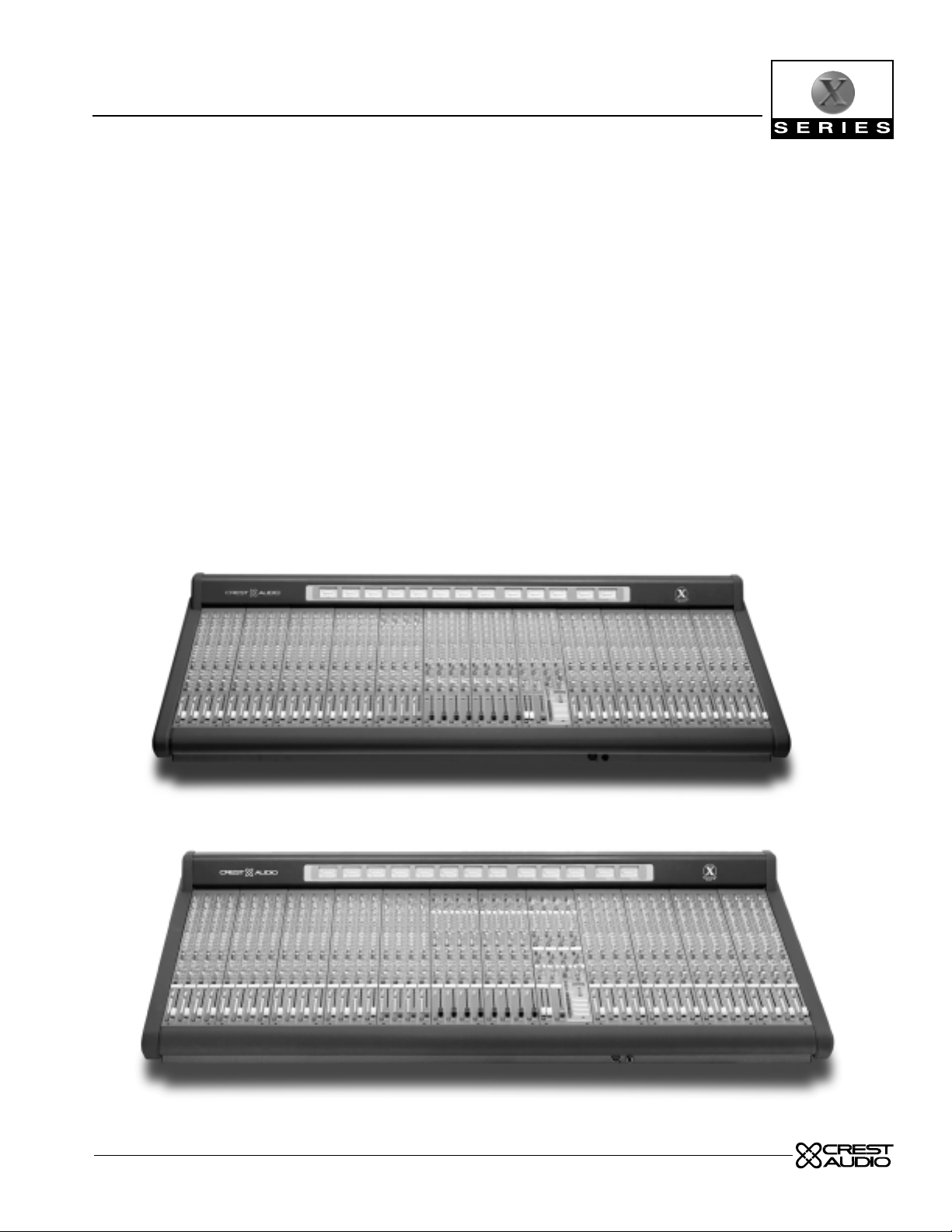
owner’s manual
X-Eight HS and RT mixing consoles
Page 2
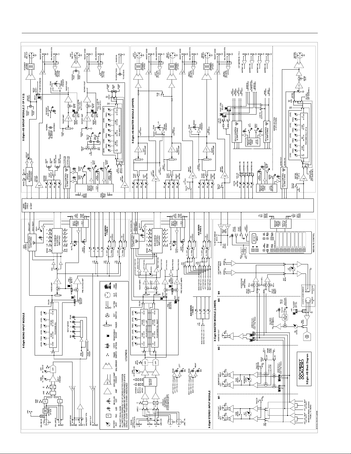
X-Eight owner’s manual
HS block diagram
2
5
5
1
3
7
7
Page 3

1
2
3
4
5
groups HS p. 41
groups RT p. 59
master HS p. 73
6
master RT p. 101
7
micro muting system p. 125
8
power supply p. 141
stereo inputs p. 25
mono inputs p. 7
table of contents
Page 4
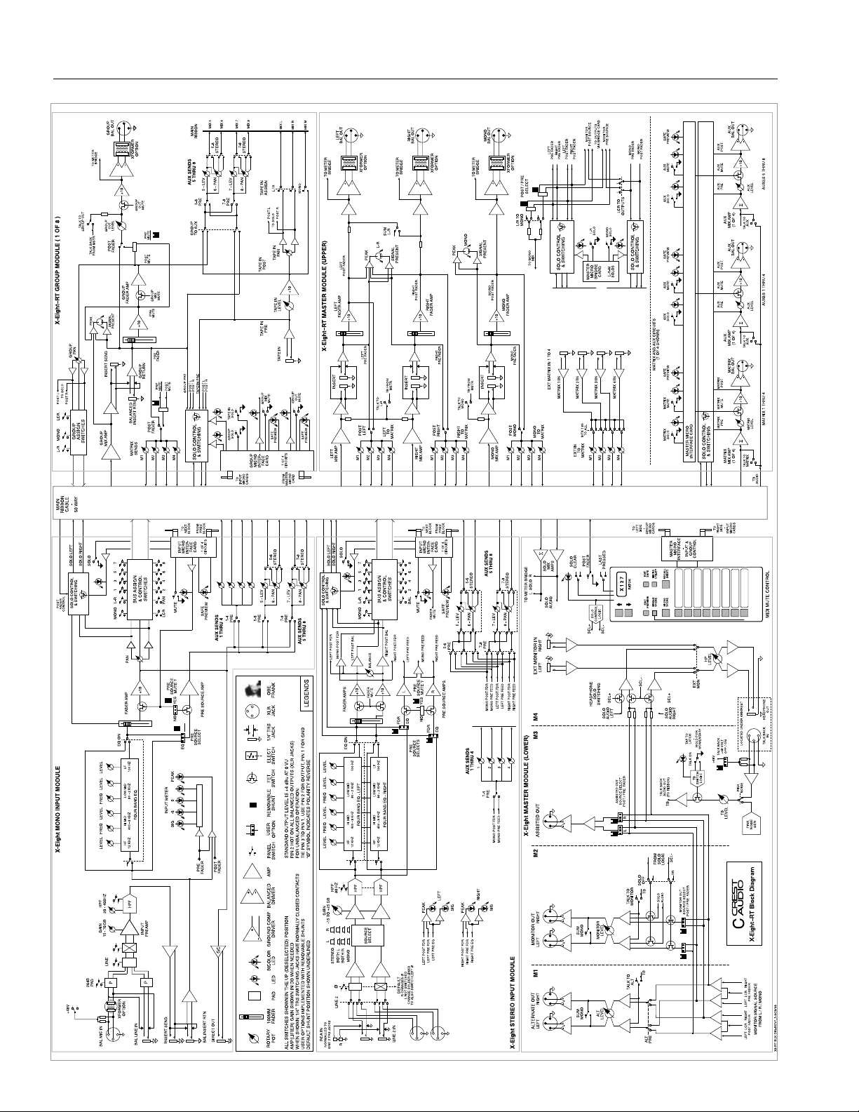
X-Eight owner’s manual
RT block diagram
OFF
SCL+
∑
Ø
1+8234
LINE 1 IN
L
R
L
R
L
R
L
LF
2
4
6
6
1
7
7
Σ
Σ
POST FADER CTRL
FDR
Σ
Σ
MUTE SCENE SELECT
GC
P
LR
Page 5

how to use this manual
conventions
terms
indicators or controls employed on the X-Eight console
will appear as:
TERMS
tasks
are broken down into steps
1
2
3
warnings
indicators
tips
see
see—references other sections of the manual containing
supplementary information on the current topic or a related issue
Prefered methods.
Helpful hints.
Feature insights.
+
Procedures not to attempt.
Issues or hazards to keep
in mind when operating
the equipment.
a
What to look
for on-screen.
Alerts, indicators, or
prompts that may appear.
®
Page 6
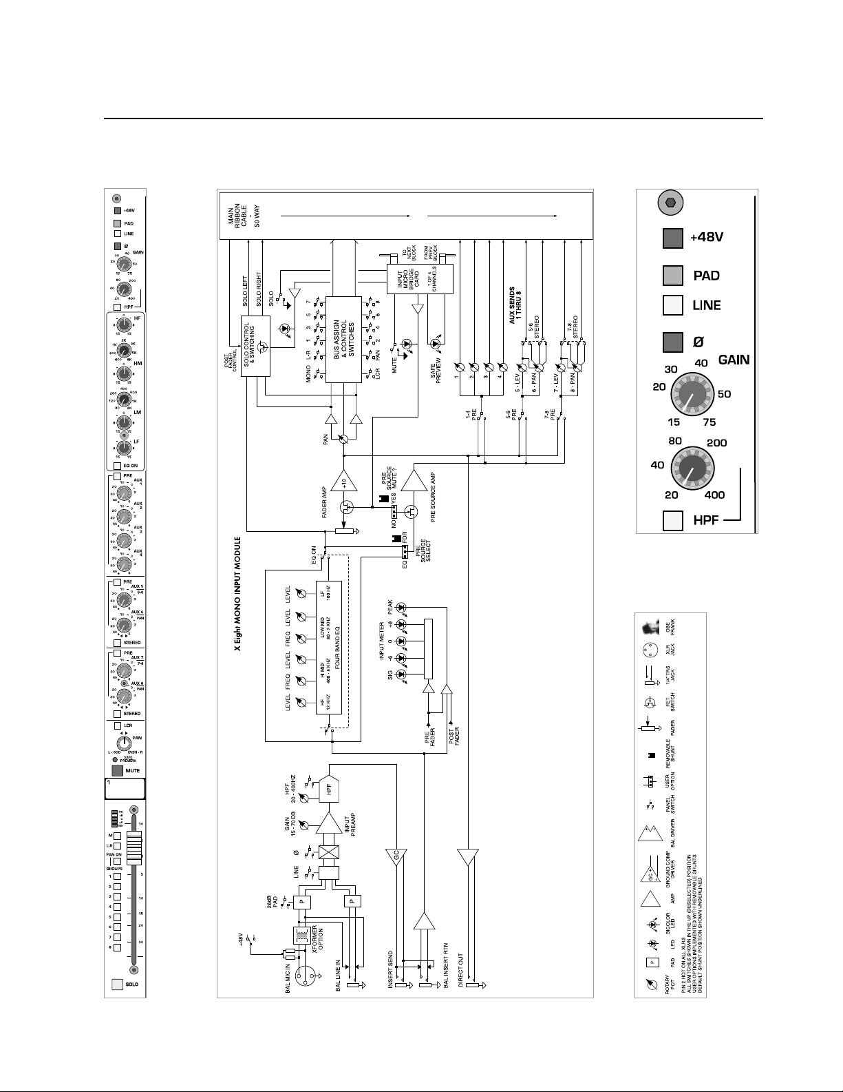
p.6
X-Eight owner’s manual
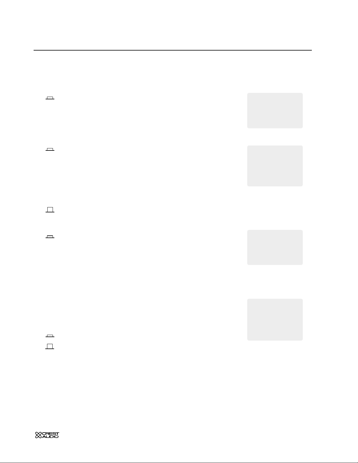
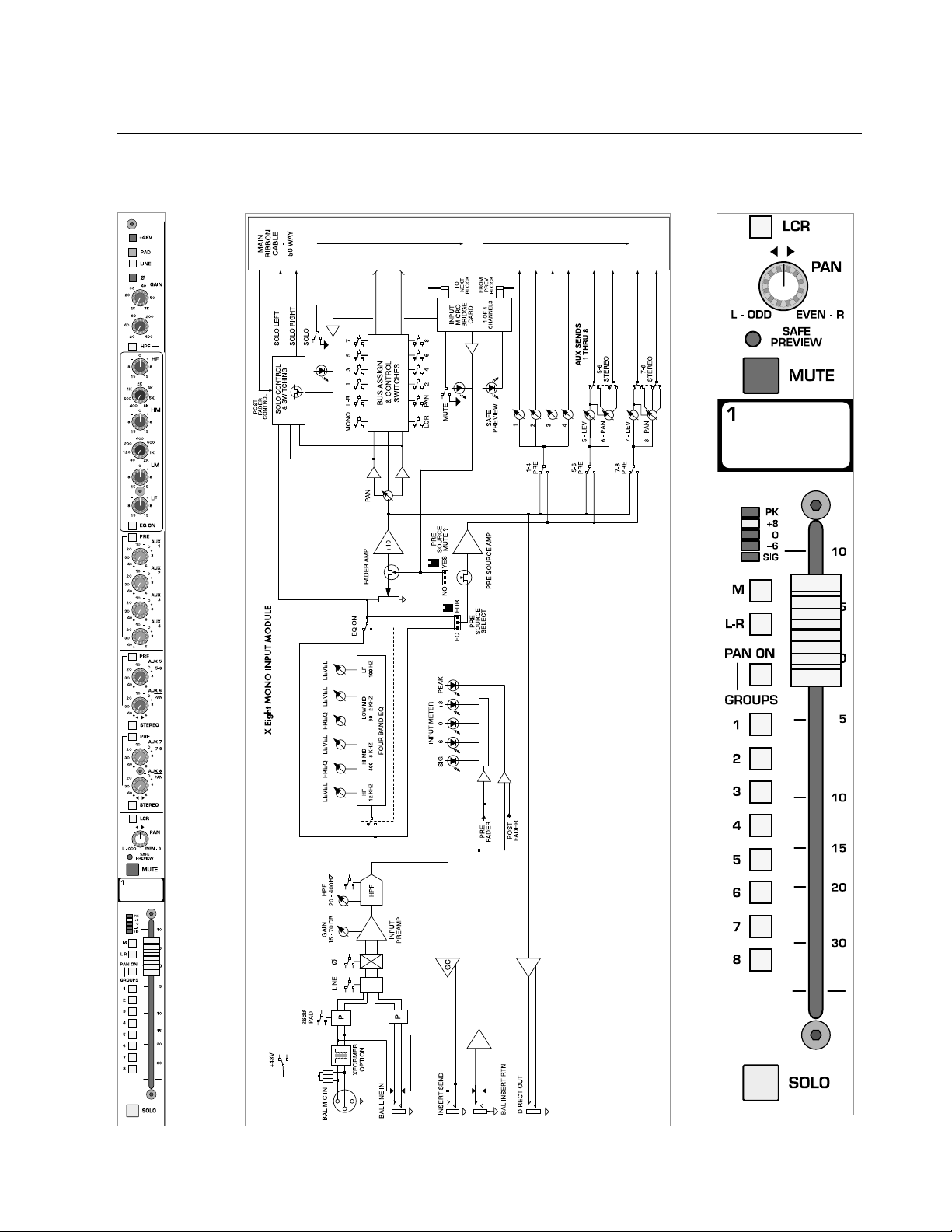
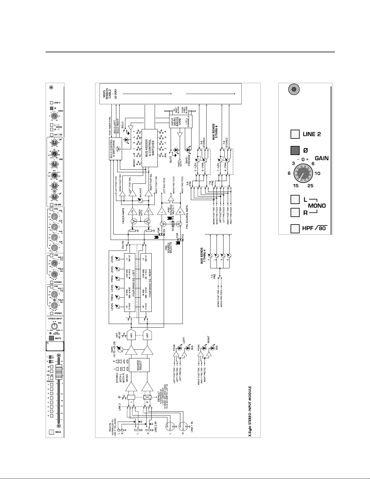
mono input module
module
panel
legend
block diagram
1
Page 7
p.7
mono input module
features
phantom power—+48V
48 volts DC is applied to pins 2 and 3 on the mic-input XLR connector. This option is used with condenser microphones and active dir ect
boxes that require an external DC voltage (phantom power) in order to
operate.
pad
The mic-input signal is attenuated by 20dB to prevent some signals
(e.g.kick drum or lead vocal) from overloading the preamp stage.The pad
is used to bring a hot mic-input signal down to a controllable level. The
20dB pad is not functional when the
LINE switch is depressed.
line
The input preamp circuit is set up to accept a mic-level signal. This
signal is brought in via the XLR mic-input connector located on the rear
panel.The 1/4" TRS input jack is disabled.
The input preamp circuit is set up to accept a line-level signal from
either the XLR mic-input connector or the 1/4" TRS input jack,both located on the rear panel.
When a plug is inserted into the 1/4" TRS input jack, the XLR mic-input
connector is disabled.
polarity reverse—ø
This feature is used for correcting or minimizing polarity and phase related errors. For example, occasionally a balanced input connection is
reverse-wired before it gets to the mixing console. This can happen in
microphones,or in snake line interfaces.By using the polarity reverse feature,this type of error can be corrected.
polarity inverted
polarity not inverted
If the channel peak
LED is illuminated,
first try lowering
the input gain control.
Only when this method is
unsuccessful should the pad
switch be engaged.
+
If the 48V phantom
power switch is
engaged, depressing this
switch disconnects phantom
power from the mic input
XLR.
+
1
When similar signals
from different channels are combined, phase
cancellations can occur.
Reversing the polarity of an
input signal often corrects
such phasing errors.
+
The 48V switch should
not be engaged when
using standard (dynamic)
microphones, or other
sources that do not use
phantom power.
a
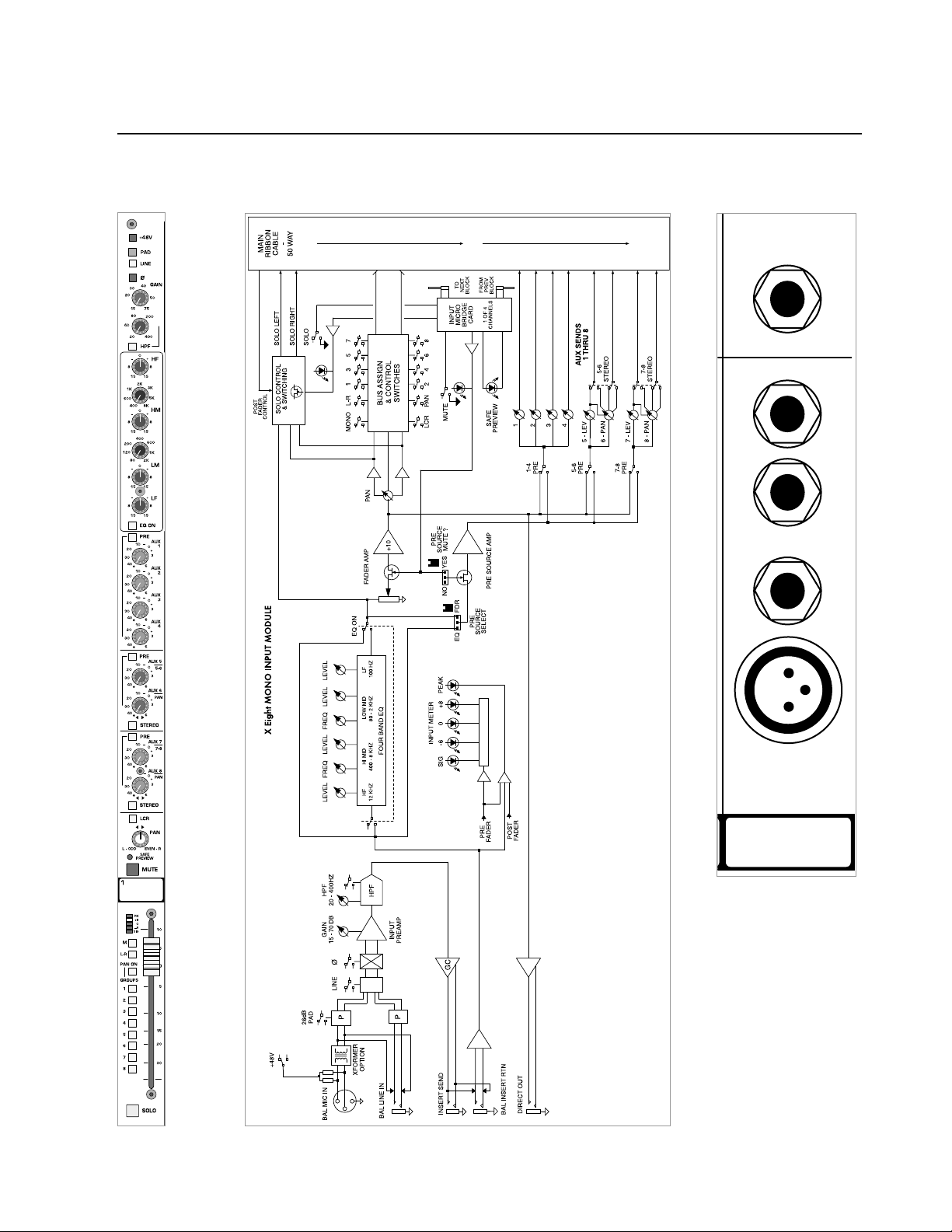
Page 8

p.8
X-Eight owner’s manual
mono input module
module
panel
legend
block diagram
1
Page 9
p.9
mono input module
features
gain
The Input gain control range is closely related to the status of the
PAD
switch and the
LINE switch. In order to establish proper gain structure in
the console,input gain settings must be set correctly.
LINE—switch-up PAD—switch-up
15 to 75dB of gain can be added the mic-input signal.
The impedance at the input XLR is 4kΩ.
LINE—switch-up PAD—switch-down
-5 to 55dB of gain can be added to the mic-input signal.
The impedance at the input XLR is 4kΩ.
LINE—switch-down PAD—switch-up or -down
-10 to 45dB of gain can be added the line-input signal.
The impedance at the input XLR and input 1/4" TRS is 20kΩ.
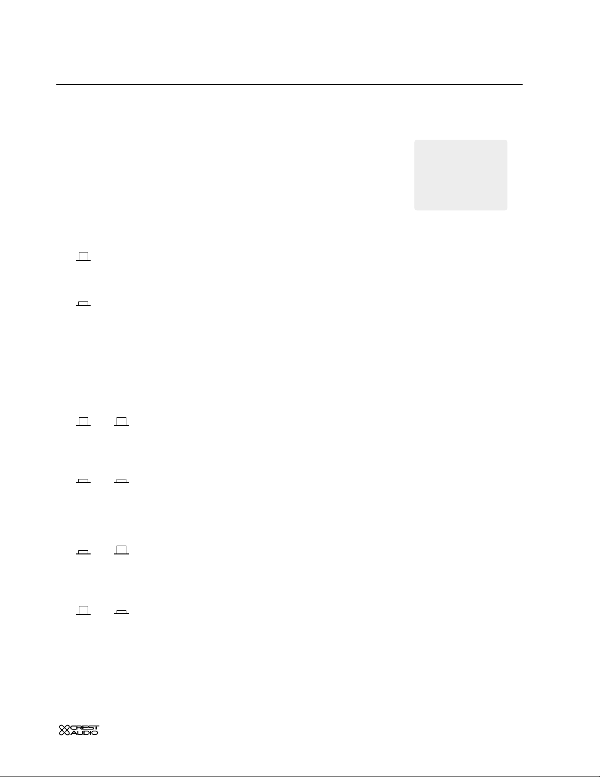
high-pass filter—HPF
Proper use of the high-pass filter reduces or eliminates unwanted low fr equencies without substantially affecting the program material.Quite often
such unwanted low frequencies are included with in-coming mic- or lineinput signals.For example,stage rumble or wind can be picked up through
vocal mics.The slope of the high-pass filter is 12dB per octave.
HPF
High-pass filter is on.
HPF—variable control
When the high-pass filter is on, this control selects a frequency
between 20Hz and 400Hz as the point where attenuation begins.
1
If the channel peak
LED is illuminated,
first try lowering
the input gain control.
Only when this method is
unsuccessful should the pad
switch be engaged.
+
Page 10
1
p.10
X-Eight owner’s manual
mono input module
module
legend
block diagram
panel
Page 11

p.11
mono input module
EQ features
Many audio signals coming into the console require some degree of corrective eq in order to be part of a good sounding mix.
The input eq consists of four-bands: high, high-mid, low-mid and low.
The high and low bands hav e fixed frequencies while the high-mid and lowmid bands are sweepable,with their higher and lower frequencies overlapping adjacent bands.
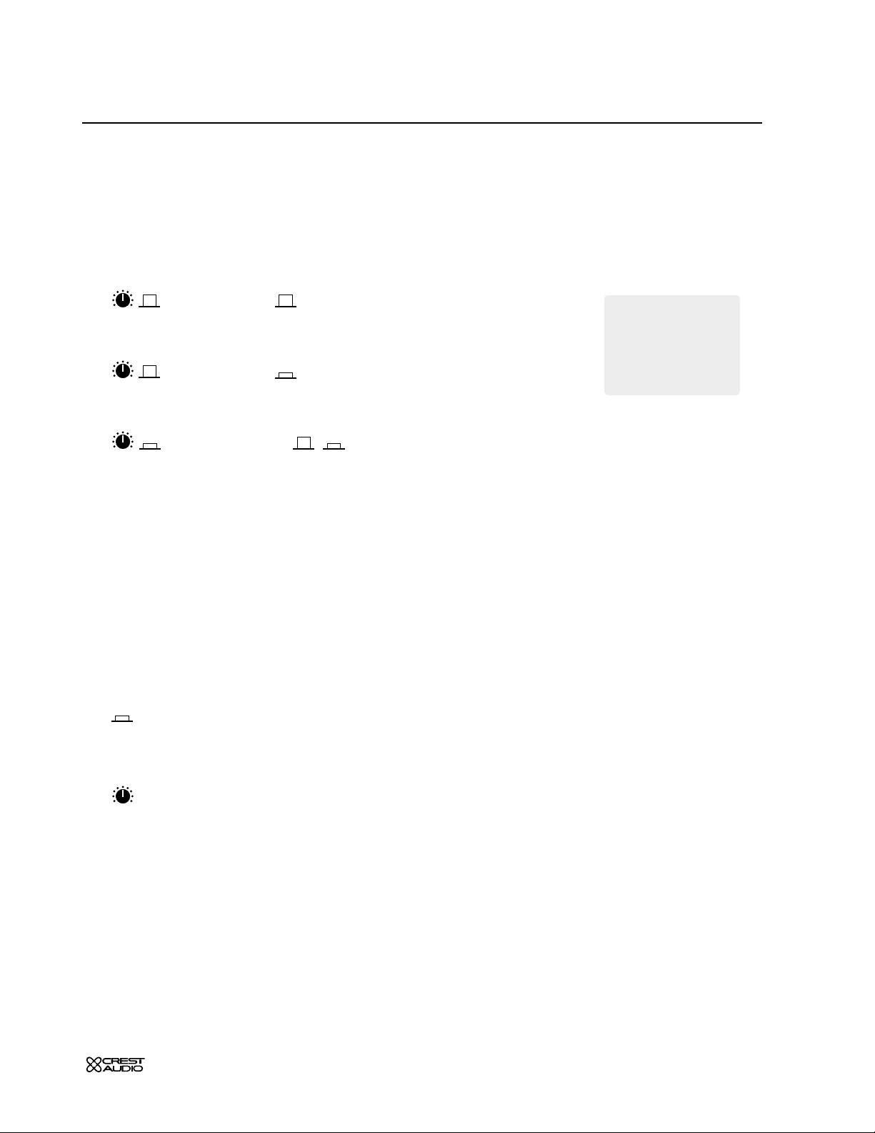
high frequency—HF
15dB boost and cut at 12kHz—Shelving Response.
high-mid frequency—HM
15dB boost and cut.
Selectable frequency range of 400Hz to 8 kHz.
The response is bell-shaped with a fixed Q of 1.5
low-mid frequency—LM
15dB boost and cut.
Selectable frequency range of 80Hz to 2kHz.
The response is bell-shaped with a fixed Q of 1.5
low frequency—LF
15dB boost and cut at 80Hz.
The boost response is bell-shaped and the cut response is shelving.
eq on
Equalizer is on. This switch can be used to make A/B comparisons
between "flat" and eq'd signals.
1
Page 12
1
p.12
X-Eight owner’s manual
mono input module
module
panel
block diagram
Page 13

p.13
mono input module
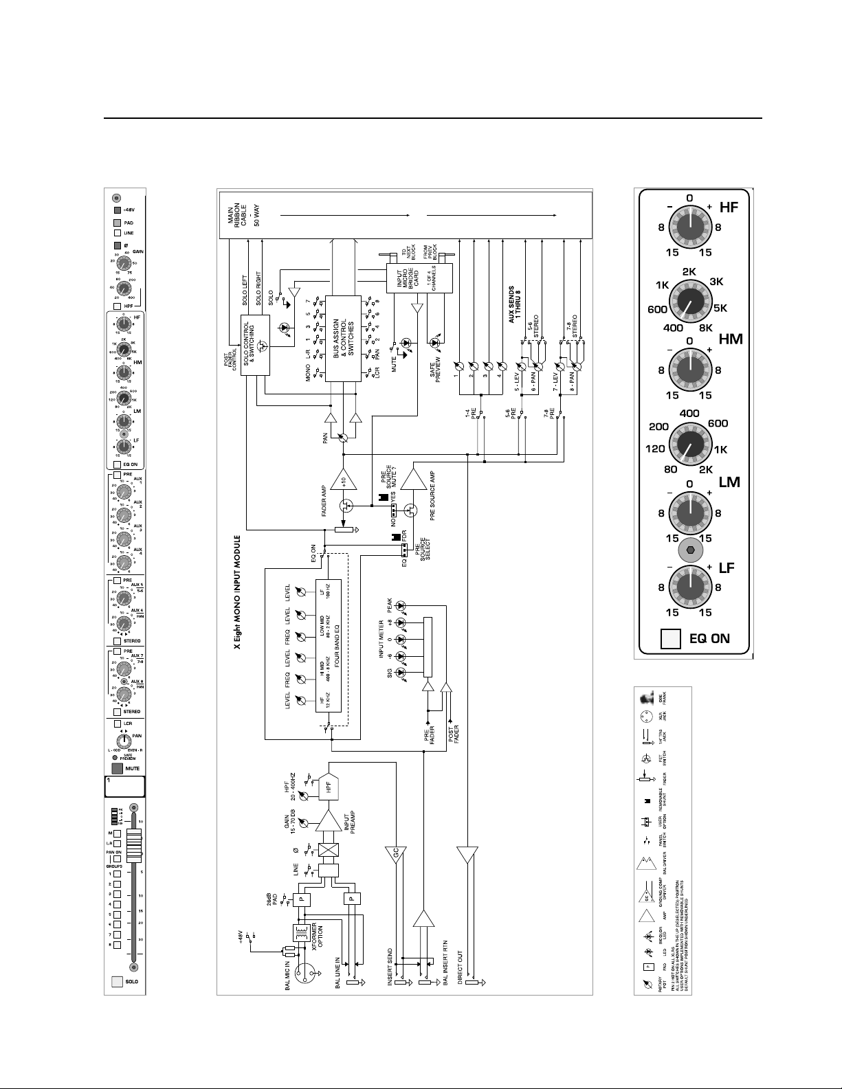
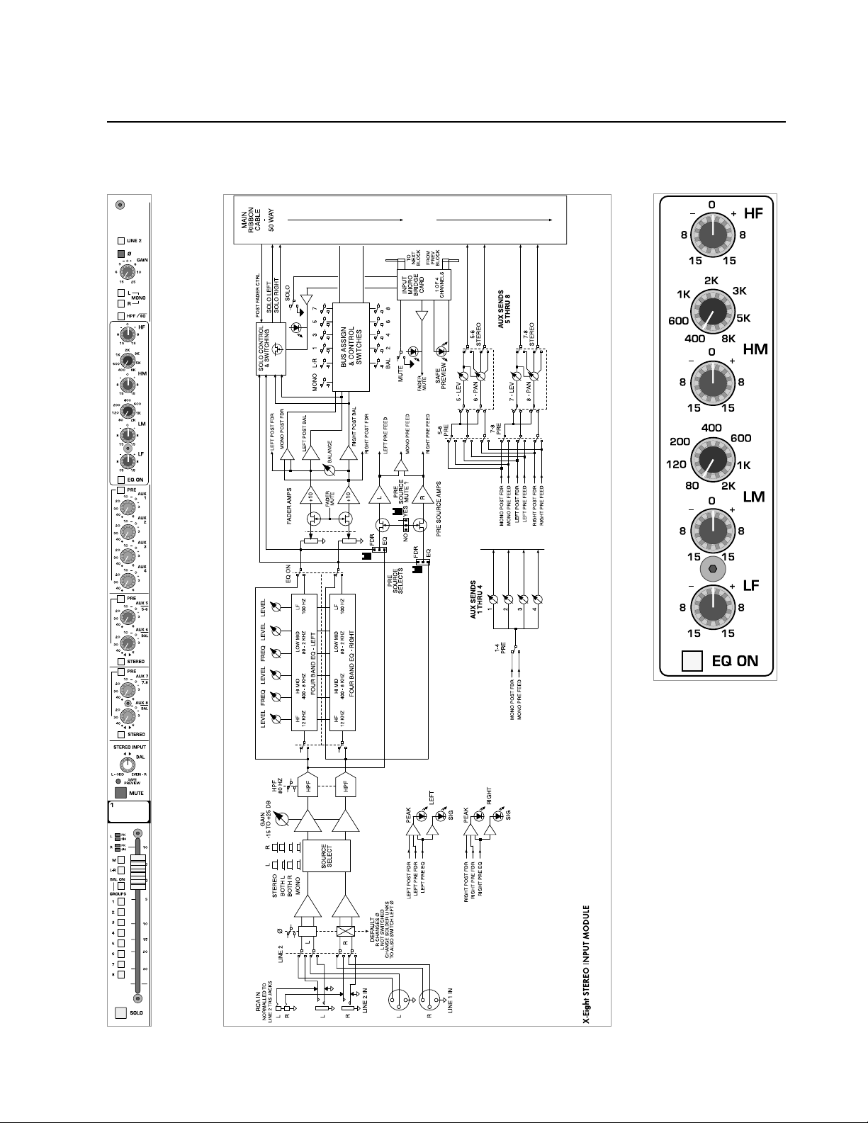
aux send features
Eight auxiliary
AUX SENDS are available for creating individual output mix es.
These mixes can be used for driving effects pr ocessors,providing monitor
mixes, creating broadcast or alternate sound reinforcement mixes, or
other special requirements.
aux sends 1–8
These knobs adjust the amount of signal sent to the AUX buses.
Unity gain occurs at the zero setting.
AUX 6 and 8 controls pan function
when selected for stereo operation.
aux 1–4, 5/6 and 7/8 pre-fader—PRE
The default signal source for the AUX SENDS is post-fader.These switches
are used for selecting the pre-fader signal for their respective auxes. The
pre-fader signal is derived post-mute and post-eq.
see—internal jumper options
AUX SENDS
are post-eq,post-mute,and post-fader.
AUX SENDS are post-eq,post-mute, and pre-fader.
aux stereo 5/6 and 7/8
The default configuration for
AUX
5,6,7 and 8 is mono,as with AUX 1–4.
In situations where stereo-aux signals are required (such as driving stereo
in-ear monitors or effects processors),these switches reconfigure the
AUX
SENDS
to operate in stereo by changing the functions of the potentiometers.
AUXES are configured as individual mono sends.
AUXES are configured as level and pan for stereo operation.
1
Page 14

1
p.14
X-Eight owner’s manual
mono input module
module
panel
block diagram
Page 15
p.15
mono input module
bus assignment features
The Input bus assignment section offers considerable flexibility for creating what eventually becomes the main output mix.Such features as
LCR,
GROUP PAN ON
and eight-individual group assignments allow several
approaches to building the desired mix.All assignments are derived postfader, post-eq,and post-mute.
left-center -right—LCR
This feature is used to precisely position a signal in a sound system with a
center speaker cluster in addition to left and right clusters.The
PAN control
becomes an integral part of how the input-signal is sent to the
LEFT,CEN-
TER,and RIGHT outputs.
The post-fader signal is assigned to the
LEFT,RIGHT
,and MONO/
CENTER
buses.Relative amounts of the signal fed to each bus is determined by the
position of the
PAN contr ol.
pan control
The pan control positions the signal within the stereo left/right field,
(or between left/center or center/right in
LCR mode).The signal must be
assigned to either LCR or the L-R bus for the pan control to have any
affect.
see—left-center -right
safe preview—LED
Green steady
This means that the mute function is in safe-mode.If the channel is part
of a mute scene,it will not be activated when the scene is recalled.The
local mute function operates normally regardless of whether or not the
channel is in safe-mode.
Green flashing
The micro mute system is in edit-safe mode,and the channel is included
in the safe-scene.Pressing the local mute button will include or exclude
the mute from the safe-scene.
Pressing the edit-safe button in the micro channel section will r emov e the
console from edit-safe setup mode and save any changes that have been
made to the safe-scene. At this point, the green-
LED will stop flashing.
The green-
LED will light steadily if the channel is part of the safe-scene, or
extinguish if it is not part of the safe-scene.
1
When in safe-mode,
a channel will not
accept commands for any
external source.
Commands sent from the
master onboard processor
and any external MIDI
device will also be ignored.
+
green-LED status
flashing green
edit-safe mode
channel included in safe-scene
steady green
part of the safe-scene
no light
not part of the safe-scene
®
LED
LED
Page 16
1
p.16
X-Eight owner’s manual
mono input module
module
panel
block diagram
Page 17
p.17
mono input module
bus assignment features
safe preview—LED
Red steady
This indicates that the mute has been activated by the micro mute section and is part of the current mute scene.
Red flashing
This indicates that the micro mute system is in edit-preview mode and
the channel is part of the mute scene that is currently being created or
edited.Pressing the local mute button will include or exclude the channel
from the selected mute scene.
Pressing the edit-preview button (
LED-off) in the micro mute section will
remove the console from edit-preview mode and save any changes that
have been made to the selected m ute scene. At this point,the red-
LED will
stop blinking.
The red-
LED will light steadily if the channel is part of the active mute
scene,or extinguish if it is not part of the active mute scene.
see—microprocessor muting
mute
The Mute switch has three functions:
1 It acts primarily as a local mute switch by activating and deactivating the
mute. When any mute is activated locally,it will remain muted until it is
deactivated locally regardless of whether or not the mute is part of the
safe-set or an active mute scene (or a mute scene that has been made inactive).
2 It is used in creating and editing mute scenes when the micro-
processor mute section is in edit-preview mode.
3 It is used for including and excluding the mute in the safe-set when the
microprocessor mute section is in edit-safe mode.
This switch is illuminated whenever the channel is muted.
see—microprocessor muting
write-in label
This label may be written on with a grease-marker,and later wiped clean
with a cloth moistened with isopropyl/rubbing alcohol.Masking tape may
also be placed on this surface,if desired.
1
red-
LED status
flashing red
edit-preview mode
channel in mute scene
steady red
part of active mute scene
no light
not part of mute scene
®
LED
LED
Page 18
1
p.18
X-Eight owner’s manual
mono input module
module
panel
block diagram
Page 19

p.19
mono input module
level meter features
level meter
Each input includes a five-segment
LED meter
for visually monitoring signal levels.This is essential f or setting up and maintaining proper gain structure.
peak indicator—PK
The input signal is monitored at several points throughout the channel. These points are the mic preamp, the EQ stage and the fader stage.
Overloads at any of these stages will cause the red peak-
LED to light.
Then the channel gain should reduced.
signal level LED’s
These three LED's light up at +8—yellow, 0—green, and -6 dB—
green. This level range -6 to +8 is the optimum operating range.
Compressed or relatively constant signals should remain close to 0.
signal present indicator—SIG
This green-LED varies in brightness in response to signal levels
between -40 dB and -6 dB.
Occasional flashing of the
peak LED is acceptable,
but frequent flashes indicate that channel levels
must be lowered.
®
1
If the channel peak
LED is illuminated,
first try lowering
the input gain control.
Only when this method is
unsuccessful should the pad
switch be engaged.
+
LEDLEDLEDLEDLED
LED
LED
LED
Page 20
1
p.20
X-Eight owner’s manual
mono input module
module
panel
block diagram
Page 21
p.21
mono input module
bus assignment features
mono assignment—M
The signal is assigned to the discrete mono bus.
When the
LCR button is depressed,this switch is bypassed.
left / right assignment—L-R
The Input signal is assigned to the main Left and Right output buses,
deriving its signal after the channels pan system.When the LCR button is
depressed,this switch is bypassed.
pan on—groups—PAN ON
The eight
GROUP assignment switches assign the input signal in mono,
independent of the pan pot.
The eight
GROUP assignment switches assign signals as four stereo-
pairs.The
PAN control governs the stereo placement of the four stereo-
pairs,which are now configured as odd–left / even–right.
For example:
GROUP 1—left,GROUP 2—right,GROUP 3—left,GROUP4—right,
...continuing through
GROUP
8.
group 1–8 assignment
The input channel's post-fader signal is assigned to the corresponding
GROUP bus(es).
see—pan on—groups
input fader
The input fader is the primary level control for signals being sent to any of
the console's mix buses.The only signals not affected are
AUX sends select-
ed to be pre-fader. The fader offers greater than 80dB of attenuation and
up to 10dB of boost.Normal operation is between -10 and 0.
solo
Pressing this switch will include (illuminated) or exclude (not-illuminated) the input channel from the console's
SOLO system.
see—master module,solo control system
Always turn off and
disconnect the amplifier from mains voltage
before making audio
connections.
As an extra precaution, have
the attenuators turned down
during power-up.
+
1
Page 22
1
p.22
X-Eight owner’s manual
mono input module
module
panel
block diagram
Direct
Out
I
n
s
e
r
t
Bal Line In
S
e
n
d
R
e
t
u
r
n
Bal Mic In
Page 23
p.23
mono input module
rear panel features
direct out 1/4" TRS
jack
The input channel's signal is available at this output jack.The
default signal routing is derived post-fader,post-eq and post-mute.This
output jack is ground-compensated.
insert points
Separate 1/4" TRS
jacks provide the facilities for inserting an external sig-
nal processor into the signal path of the input channel.
insert send
This jack serves as an output for connection to the input of a
signal processor.The signal is derived after the mic preamp and
HPF but
before the eq section.Plugging a
1/4" TRS plug into this jack does not break
the signal flow of the channel.This output jack is ground-compensated.
insert return
The output of a signal processor is fed to this jack.It can accept
a balanced or unbalanced signal and is located pre-eq.Plugging a
1/4" TRS
plug into this jack does break the signal flow of the channel.
balanced line-in jack—Bal Line In
Line-level signals,balanced or unbalanced,may be brought into
the input channel through this jack.The
LINE switch must be depressed for
this jack to be active.
balanced mic-in xlr connector—Bal Mic In
This balanced female XLR accepts a low-impedance microphone
signal,or a line-level signal,depending on position of the LINE switch on
the front panel.
see—mono input module,phantom power,line
In situations where
the preamp circuitry is
not needed, the Insert
Return can be used as the
channel’s input.
For example, when using an
expensive tube mic preamp.
+
The insert send can
also be used as an
additional channel output
when s pre-EQ signal is
needed.
+
1
Page 24
p.24
X-Eight owner’s manual
stereo input module
module
panel
block diagram
2
Page 25
p.25
stereo input module
features
The stereo input module can be configured to operate as either stereo or
mono. When configured to operate in mono,many features are identical
to those of the mono input module.
line select—Line 2
This switch determines selection of input signals from the three sets of
rear panel connectors.
The channel is in
LINE 1 MODE.The signals are brought in via the left
and right line-input
XLR
s located on the rear panel.
The channel is in
LINE 2 MODE.The signals are brought in via the RCA
line-input connectors which are normalled through the
1/4" TRS
line-input
jacks.Insertion of a plug into the
1/4" jack disconnects the RCA jacks.
left and right mono-switches
These switches provide several options for configuring the stereo lineinput module as a mono line-input module.
left right
Signals brought into the left and right inputs are tr eated as stereo
throughout the module.
left right
Signals brought into the left and right inputs are summed together immediately before the
GAIN control.The summed signal is treated as mono
throughout the rest of the module.
left right
The signal fed to the left input is treated as a mono signal throughout the
module.No signal from the right input is used.
left right
The signal fed to the right input is treated as a mono signal throughout
the module.No signal from the left input is used.
2
To avoid redundancy,
mono features will refer
back to corresponding sections on the Mono module.
Descriptions given here are
specifically for the default
Stereo configuration.
+
Page 26

p.26
X-Eight owner’s manual
stereo input module
module
panel
block diagram
2
Page 27

p.27
stereo input module
features
input gain—GAIN
This control adjust the gain of the input preamp(s).
Both left and right input signals are affected by this contr ol.
polarity reverse—ø
This switch inverts the polarity of the right input signal in relation to the
left input signal.
see—mono input module
Polarity of the right input signal is inverted.
Polarity of the right input signal is not inverted.
high-pass filter—
HPF
The high-pass filter is activated for signals coming into both the left and
right inputs. The shelving frequency is fixed at 80Hz with a slope of 12dB
per octave.
Proper use of the high-pass filter reduces or eliminates unwanted low fr equencies,without substantially affecting the program material.Quite often
such unwanted low frequencies are included with in-coming mic- or lineinput signals.For example,stage-rumble or wind can be picked up through
vocal mics.
2
Page 28
2
p.28
X-Eight owner’s manual
stereo input module
module
panel
block diagram
Page 29

p.29
stereo input module
four-band stereo
EQ features
Although left and right signals are processed separately,the parameters are
set in tandem by common front-panel controls.
see—mono input module
high frequency—HF
15dB boost and cut at 12kHz—shelving response.
high-mid frequency—HM
15dB boost and cut.
Selectable frequency range of 400Hz to 8 kHz.
The response is bell-shaped with a fixed Q of 1.5
low-mid frequency—LM
15dB boost and cut.
Selectable frequency range of 80Hz to 2kHz.
The response is bell-shaped with a fixed Q of 1.5
low frequency—LF
15dB boost and cut at 80Hz.
The boost response is bell-shaped and the cut response is shelving.
equalizer—EQ ON
Equalizer is on. This switch can be used to make A/B comparisons
between "flat" and eq'd signals.
2
Page 30
2
p.30
X-Eight owner’s manual
stereo input module
module
panel
block diagram
Page 31

p.31
stereo input module
aux send features
The following descriptions apply to the stereo line input module when
configured for stereo operation.
see—mono input module for mono operation
aux send 1–8 controls
These knobs adjust the amount of signal sent the AUX buses.
AUX 1–4 are fed from a summed-mono source. AUXES 5–8 are also fed
from this mono source,but can be switched to stereo operation.
see—stereo balance
aux 1-4,5/6 and 7/8 pre-fader—PRE
The default signal source for the AUX SENDS is post-fader.These switches
select a pre-fader source for their r espective auxes.The pre-fader signal is
derived post-mute and post-eq.
see—internal jumper options
Corresponding
AUX SENDS
are post-eq,post-mute and post-fader.
Corresponding
AUX SENDS are post-eq,post-mute and pre-fader.
stereo balance 5 and 6—STEREO
AUX 5 and 6 are mono.
AUX 5 control acts as a left and right level-control and AUX 6 control
acts as a left/right balance-control.
stereo balance 7 and 8—
STEREO
AUX 7 and 8 are mono.
AUX 7 control acts as a left and right level-control and AUX 8 control
acts as a left/right balance-control.
2
Page 32

2
p.32
X-Eight owner’s manual
stereo input module
module
panel
block diagram
Page 33

p.33
stereo input module
bus assignment features
balance control
The Balance control adjusts the Stereo balance for Left/Right and the
Group Assignment section when in Balance mode.
When the Stereo Line Input module is being used as a Mono input,both
(left and right select switches depressed) the Balance control functions as
a Pan control.
safe preview LED
see—mono input module for full description
mute
see—mono input module for full description
write-in label
This label may be written on with a grease-marker,and later wiped clean
with a cloth moistened with isopropyl/rubbing alcohol.
2
Page 34

2
p.34
X-Eight owner’s manual
stereo input module
module
panel
block diagram
Page 35

p.35
stereo input module
bus assignment features
peak indicator—A separate PK and SIGLED is provided for left
and right
The input signal is monitored at several points throughout the channel. These points are the mic preamp, the EQ stage and the fader stage.
Overloads at any of these stages will cause the red peak-
LED to light.
Then the channel gain should reduced.
signal present indicator—SIG
This green-LED varies in brightness in response to signal levels
between -40 dB and -6 dB.
mono assignment—M
The input signal is assigned to the discrete mono bus.Left and right
signals are summed to make up the mono or center signal.
left/right assignment—L/R
The stereo input signals are assigned directly to the main left and
right output buses.
The proportion of left vs.right can be adjusted by the
BALANCE
control.
Best operation occurs when
the green LED is brightly
illuminated and the red
LED
occasionally flickers.
®
2
LED
LED
Page 36

2
p.36
X-Eight owner’s manual
stereo input module
module
panel
block diagram
Page 37

p.37
stereo input module
bus assignment features
balance on—groups—BAL ON
The left and right signals are summed as mono to make up the gr oup
assignment signals.
The left and right signals are assigned in stereo to the groups in
odd/even pairs.
GROUP assignment switches 1,3,5 and 7 carry the left input-
signal and
GROUP assignment switches 2,4,6 and 8 carry the right input-sig-
nal.
The proportion of left vs.right can be adjusted by the
BALANCE control.
group 1–8 assignment
The input channel's post-fader signal is assigned to the corresponding
GROUP bus(es).
see—balance on—groups
input fader
The input fader is the primary level control for signals being sent to any of
the console's mix buses.The only signals not affected are
AUX sends select-
ed to be pre-fader. The fader offers greater than 80db of attenuation and
up to 10db of boost.Normal operation is between -10 and 0.
solo
Pressing this switch will include (illuminated) or exclude (not-illuminated) the input channel from the console's
SOLO system.The channel is
Solo'd in stereo.
see—master module,solo control system
2
Page 38

2
p.38
X-Eight owner’s manual
stereo input module
module
panel
Bal Line In 2
L
R
Bal Line In 1
L
R
Line In 2
L
R
block diagram
Page 39

p.39
stereo input module
rear panel features
The stereo line-input module provides connectors for three stereo linelevel signals.
see—line 2 switch.
balanced left and right line-in XLR
connectors
These two jacks accept balanced or unbalanced +4dB line level signals.The
LINE 2 switch on front-panel must be disengaged for these connectors to
be active.
line-input left and right 1/4" TRS jacks
These two jacks accept balanced or unbalanced line level signals.The LINE
2 switch on front panel must be engaged for these jacks to be active.
line-input left and right
RCA connectors
These two jacks accept unbalanced line-level signals.They are activ e when
the
LINE 2 switch on front-panel is engaged and nothing is plugged into the
corresponding left or right
1/4" TRS jack(s).
2
Page 40

p.40
X-Eight owner’s manual
group HS module
module
panel
block diagram
CABLE
3
GROUP
BAL OUT
OPTION
XFORMER
GROUP
FADER
X-Eight–HS GROUP MODULE (1 OF 4 X 2)
PAN
GROUP
L-R
GROUP
MONO
FEED
METER
SELECT
GROUP
OP FEED
POST
POST
ROTARY
SWITCHES
GROUP
BUS ASSIGN
INSERT SEND
GC
TO METER BRIDGE
FADER
MIX AMP
∑
REVERSE
FADER
SENDS
MATRIX
M1
PEAK
AUX / GROUP
NORMAL
SYMBOLS
ALL SWITCH
PRE
ROTARY
POST
M2
BAL INSERT RTN
IN GROUP
PRE
GROUP
GROUP
(TO EQ)
RETURN
REVERSED
MATRIX
POST FADER
MATRIX
M3
M4
SIGNAL
PRESENT
FADER AMP
PRE
FADER
POST
POST ROTARY
FADER PRE
SOLO CONTROL
AUX
BAL OUT
POST
ROTARY
FADER POST
FADER
PRE
MUTE
+10
MATRIX
POST
ROTARY PRE
& SWITCHING
MUTE
POST
FADER
POST
FADER
FADER TO MATRIX
MUTE
ROTARY
FADER
POST
PRE / POST
MUTE SELECT
ROTARY AMP
PRE
ROTARY
BUS
GROUP
SOLO
SOLO
TO
INPUT
INSERT SEND
ROTARY POST
MICRO
CARDS
BAL INSERT RTN
GC
AUX
(TO EQ)
RETURN
MUTE
ROTARY
PRE / POST
MUTE SELECT
ROTAR Y T O MA TRIX
LEVEL
PRE
POST
MUTE
MUTE
+10
FADER
TALK TO
TB
AUDIO
MICRO
GROUP
BRIDGE
MATRIX
FADER
CARD
POST
TALK TO
MUTE
ROTARY
ROTARY
SAFE
1 OF 4
AUX
BUS
PREVIEW
CHANNELS
FROM
LEVEL
LEVEL
LEVEL
LEVEL
MICRO
MASTER
CARD
EQ
FREQ
FREQ
FREQ
FREQ
ROTARY
ROTARY
TO
EQ
MUTE
PRE
GROUP
ON
SAFE
FADER
PREVIEW
FADER IN
TO GROUP BUS
PRE
LF
LO MID
MIDHI MIDHF
PRE
ROTARY
FIVE BAND EQ
400 TO 8K 200 TO 4K 100 TO 2K12K 40 TO 400
AUX
GROUP
RETURN
RETURN
AUX
TO AUX BUS
MIX AMP
∑
50 WA Y
Page 41

p.41
group HS module
output eq
features
The HS output-section includes twelve output-equalizers occupying the
upper portions of the eight
GROUP sub-modules and the four MASTER sub-
modules.
By using designated assignment switches, output eq’s can be fed by the
eight
AUXES or GROUPS,the four matrix masters or left,right,and mono mas-
ters.Each eq features five-bands of equalization,making them ideal for feeding on-stage or in-ear monitors.
high frequency—HF
15dB boost and cut at 12kHz—shelving response.
high-mid frequency—HM
Selectable frequency range of 400Hz to 8 kHz.
The response is bell-shaped with a fixed Q of 1.5
15dB boost and cut.
mid frequency—MID
Selectable frequency range of 200Hz to 4kHz.
The response is bell-shaped with a fixed Q of 1.5
15dB boost and cut.
low-mid frequency—LM
Selectable frequency range of 100Hz to 2kHz.
The response is bell-shaped with a fixed Q of 1.5
15dB boost and cut.
low frequency—LF
Selectable frequency range of 20Hz to 400Hz.
The response is bell-shaped with a fixed Q of 1.5.
15dB boost and cut.
3
Page 42

p.42
X-Eight owner’s manual
group HS module
module
panel
block diagram
CABLE
3
GROUP
BAL OUT
OPTION
XFORMER
GROUP
FADER
X-Eight–HS GROUP MODULE (1 OF 4 X 2)
PAN
GROUP
L-R
GROUP
MONO
FEED
METER
SELECT
GROUP
OP FEED
POST
POST
ROTARY
SWITCHES
GROUP
BUS ASSIGN
INSERT SEND
GC
TO METER BRIDGE
FADER
MIX AMP
∑
REVERSE
FADER
SENDS
MATRIX
M1
PEAK
AUX / GROUP
NORMAL
SYMBOLS
ALL SWITCH
PRE
ROTARY
POST
M2
BAL INSERT RTN
IN GROUP
PRE
GROUP
GROUP
(TO EQ)
RETURN
REVERSED
MATRIX
POST FADER
MATRIX
M3
M4
SIGNAL
PRESENT
FADER AMP
PRE
FADER
POST
POST ROTARY
FADER PRE
SOLO CONTROL
AUX
BAL OUT
POST
ROTARY
FADER POST
MUTE
FADER
PRE
MUTE
+10
MATRIX
POST
ROTARY PRE
& SWITCHING
POST
FADER
POST
FADER
FADER TO MATRIX
MUTE
ROTARY
FADER
POST
PRE / POST
MUTE SELECT
ROTARY AMP
PRE
ROTARY
BUS
GROUP
SOLO
SOLO
TO
INPUT
INSERT SEND
ROTARY POST
MICRO
CARDS
BAL INSERT RTN
GC
AUX
(TO EQ)
RETURN
MUTE
ROTARY
PRE / POST
MUTE SELECT
ROTAR Y T O MA TRIX
LEVEL
PRE
POST
MUTE
MUTE
+10
FADER
TALK TO
TB
AUDIO
MICRO
GROUP
BRIDGE
MATRIX
FADER
CARD
POST
TALK TO
MUTE
ROTARY
ROTARY
SAFE
1 OF 4
AUX
BUS
PREVIEW
CHANNELS
FROM
LEVEL
LEVEL
LEVEL
LEVEL
MICRO
MASTER
CARD
EQ
FREQ
FREQ
FREQ
FREQ
ROTARY
ROTARY
TO
EQ
MUTE
PRE
GROUP
ON
SAFE
FADER
PREVIEW
FADER IN
TO GROUP BUS
PRE
LF
LO MID
MIDHI MIDHF
PRE
ROTARY
FIVE BAND EQ
400 TO 8K 200 TO 4K 100 TO 2K12K 40 TO 400
AUX
GROUP
RETURN
RETURN
AUX
TO AUX BUS
MIX AMP
∑
50 WA Y
Page 43

p.43
group HS module
output EQ
features
equalizer—EQ ON
Equalizer is on. This switch can be used to make A/B comparisons
between "flat" and eq'd signals.
group equalization —per output channel—EQ TO GROUP
This switch selects the signal path for the eq.
eq to
AUX MASTERS
eq to
GROUPS
This switch can be
used to make A/B
comparisons of "flat"
and EQ'd signals.
+
3
Page 44

p.44
X-Eight owner’s manual
group HS module
module
panel
block diagram
CABLE
3
GROUP
BAL OUT
OPTION
XFORMER
GROUP
FADER
X-Eight–HS GROUP MODULE (1 OF 4 X 2)
PAN
GROUP
L-R
GROUP
MONO
FEED
METER
SELECT
GROUP
OP FEED
POST
POST
ROTARY
SWITCHES
GROUP
BUS ASSIGN
INSERT SEND
GC
TO METER BRIDGE
FADER
MIX AMP
∑
REVERSE
FADER
SENDS
MATRIX
M1
PEAK
AUX / GROUP
NORMAL
SYMBOLS
ALL SWITCH
PRE
ROTARY
POST
M2
BAL INSERT RTN
IN GROUP
PRE
GROUP
GROUP
(TO EQ)
RETURN
REVERSED
MATRIX
POST FADER
MATRIX
M3
M4
SIGNAL
PRESENT
FADER AMP
PRE
FADER
POST
POST ROTARY
FADER PRE
SOLO CONTROL
AUX
BAL OUT
POST
ROTARY
FADER POST
MUTE
FADER
PRE
MUTE
+10
MATRIX
POST
ROTARY PRE
& SWITCHING
POST
FADER
POST
FADER
FADER TO MATRIX
MUTE
ROTARY
FADER
POST
PRE / POST
MUTE SELECT
ROTARY AMP
PRE
ROTARY
BUS
GROUP
SOLO
SOLO
TO
INPUT
INSERT SEND
ROTARY POST
MICRO
CARDS
BAL INSERT RTN
GC
AUX
(TO EQ)
RETURN
MUTE
ROTARY
PRE / POST
MUTE SELECT
ROTAR Y T O MA TRIX
LEVEL
PRE
POST
MUTE
MUTE
+10
FADER
TALK TO
TB
AUDIO
MICRO
GROUP
BRIDGE
MATRIX
FADER
CARD
POST
TALK TO
MUTE
ROTARY
ROTARY
SAFE
1 OF 4
AUX
BUS
PREVIEW
CHANNELS
FROM
LEVEL
LEVEL
LEVEL
LEVEL
MICRO
MASTER
CARD
EQ
FREQ
FREQ
FREQ
FREQ
ROTARY
ROTARY
TO
EQ
MUTE
PRE
GROUP
ON
SAFE
FADER
PREVIEW
FADER IN
TO GROUP BUS
PRE
LF
LO MID
MIDHI MIDHF
PRE
ROTARY
FIVE BAND EQ
400 TO 8K 200 TO 4K 100 TO 2K12K 40 TO 400
AUX
GROUP
RETURN
RETURN
AUX
TO AUX BUS
MIX AMP
∑
50 WA Y
Page 45

p.45
group HS module
matrix features
The X-Eight HS includes four
MA TRIX outputs.Each of these outputs can be
made up of signals from the eight
GROUPS; the left, right and mono buses;
and an external source.
matrix 1–4 levels—M1,M2,M3,M4
These level controls are used to mix the group's signal into the cor-
responding matrix.
post-group
The GROUP fader setting has no effect on the group-to-matrix level
controls 1–4.
The
GROUP fader is introduced into the signal path.When the group
is muted,the matrix level controls 1–4 are muted as well.
3
Page 46

p.46
X-Eight owner’s manual
group HS module
module
panel
block diagram
CABLE
3
GROUP
BAL OUT
OPTION
XFORMER
GROUP
FADER
X-Eight–HS GROUP MODULE (1 OF 4 X 2)
PAN
GROUP
L-R
GROUP
MONO
FEED
METER
SELECT
GROUP
OP FEED
POST
POST
ROTARY
SWITCHES
GROUP
BUS ASSIGN
INSERT SEND
GC
TO METER BRIDGE
FADER
MIX AMP
∑
REVERSE
FADER
SENDS
MATRIX
M1
PEAK
AUX / GROUP
NORMAL
SYMBOLS
ALL SWITCH
PRE
ROTARY
POST
M2
BAL INSERT RTN
IN GROUP
PRE
GROUP
GROUP
(TO EQ)
RETURN
REVERSED
MATRIX
POST FADER
MATRIX
M3
M4
SIGNAL
PRESENT
FADER AMP
PRE
FADER
POST
POST ROTARY
FADER PRE
SOLO CONTROL
AUX
BAL OUT
POST
ROTARY
FADER POST
MUTE
FADER
PRE
MUTE
+10
MATRIX
POST
ROTARY PRE
& SWITCHING
POST
FADER
POST
FADER
FADER TO MATRIX
MUTE
ROTARY
FADER
POST
PRE / POST
MUTE SELECT
ROTARY AMP
PRE
ROTARY
BUS
GROUP
SOLO
SOLO
TO
INPUT
INSERT SEND
ROTARY POST
MICRO
CARDS
BAL INSERT RTN
GC
AUX
(TO EQ)
RETURN
MUTE
ROTARY
PRE / POST
MUTE SELECT
ROTAR Y T O MA TRIX
LEVEL
PRE
POST
MUTE
MUTE
+10
FADER
TALK TO
TB
AUDIO
MICRO
GROUP
BRIDGE
MATRIX
FADER
CARD
POST
TALK TO
MUTE
ROTARY
ROTARY
SAFE
1 OF 4
AUX
BUS
PREVIEW
CHANNELS
FROM
LEVEL
LEVEL
LEVEL
LEVEL
MICRO
MASTER
CARD
EQ
FREQ
FREQ
FREQ
FREQ
ROTARY
ROTARY
TO
EQ
MUTE
PRE
GROUP
ON
SAFE
FADER
PREVIEW
FADER IN
TO GROUP BUS
PRE
LF
LO MID
MIDHI MIDHF
PRE
ROTARY
FIVE BAND EQ
400 TO 8K 200 TO 4K 100 TO 2K12K 40 TO 400
AUX
GROUP
RETURN
RETURN
AUX
TO AUX BUS
MIX AMP
∑
50 WA Y
Page 47

p.47
group HS module
aux master output features
This section includes the standard output features
for
AUX SENDS 1–8.
safe preview
LED
see—mono input module for full description
mute
see—mono input module for full description
aux 1–8 output level
The AUX MASTER output level controls set the levels that appear at the
corresponding
AUX
output connectors on the rear-panel.
talk to—aux 1–8
Adds the
T ALKBACK system output to the associated AUX output.The
level of the
T ALKBACK signal is set by the TALKBACK level contr ol in the MAS-
TER
section.
solo
Pressing this switch will include when illuminated or exclude when
not illuminated the
AUX from the console's SOLO system.
see—master module, solo control system
3
Page 48

p.48
X-Eight owner’s manual
group HS module
module
panel
block diagram
CABLE
3
GROUP
BAL OUT
OPTION
XFORMER
GROUP
FADER
X-Eight–HS GROUP MODULE (1 OF 4 X 2)
PAN
GROUP
L-R
GROUP
MONO
FEED
METER
SELECT
GROUP
OP FEED
POST
POST
ROTARY
SWITCHES
GROUP
BUS ASSIGN
INSERT SEND
GC
TO METER BRIDGE
FADER
MIX AMP
∑
REVERSE
FADER
SENDS
MATRIX
M1
PEAK
AUX / GROUP
NORMAL
SYMBOLS
ALL SWITCH
PRE
ROTARY
POST
M2
BAL INSERT RTN
IN GROUP
PRE
GROUP
GROUP
(TO EQ)
RETURN
REVERSED
MATRIX
POST FADER
MATRIX
M3
M4
SIGNAL
PRESENT
FADER AMP
PRE
FADER
POST
POST ROTARY
FADER PRE
SOLO CONTROL
AUX
BAL OUT
POST
ROTARY
FADER POST
MUTE
FADER
PRE
MUTE
+10
MATRIX
POST
ROTARY PRE
& SWITCHING
POST
FADER
POST
FADER
FADER TO MATRIX
MUTE
ROTARY
FADER
POST
PRE / POST
MUTE SELECT
ROTARY AMP
PRE
ROTARY
BUS
GROUP
SOLO
SOLO
TO
INPUT
INSERT SEND
ROTARY POST
MICRO
CARDS
BAL INSERT RTN
GC
AUX
(TO EQ)
RETURN
MUTE
ROTARY
PRE / POST
MUTE SELECT
ROTAR Y T O MA TRIX
LEVEL
PRE
POST
MUTE
MUTE
+10
FADER
TALK TO
TB
AUDIO
MICRO
GROUP
BRIDGE
MATRIX
FADER
CARD
POST
TALK TO
MUTE
ROTARY
ROTARY
SAFE
1 OF 4
AUX
BUS
PREVIEW
CHANNELS
FROM
LEVEL
LEVEL
LEVEL
LEVEL
MICRO
MASTER
CARD
EQ
FREQ
FREQ
FREQ
FREQ
ROTARY
ROTARY
TO
EQ
MUTE
PRE
GROUP
ON
SAFE
FADER
PREVIEW
FADER IN
TO GROUP BUS
PRE
LF
LO MID
MIDHI MIDHF
PRE
ROTARY
FIVE BAND EQ
400 TO 8K 200 TO 4K 100 TO 2K12K 40 TO 400
AUX
GROUP
RETURN
RETURN
AUX
TO AUX BUS
MIX AMP
∑
50 WA Y
Page 49

p.49
group HS module
reverse aux
/
group
The
REVERSE AUX / GROUP feature is used to swap the functions of the
AUX
MASTER
controls and the GR OUP MASTER controls.
Swapped controls include:the
T ALK TO switch, the
SOLO switch, the MUTE
switch,the
SAFE PREVIEW LED and the MASTER LEVEL
control (via rotary con-
trol on the
AUX MASTER and a fader on the GROUP MASTER
).
reverse aux / group
red
LED
off
The
AUX 1–8 and GROUP 1–8 MASTER level controls,SAFE PREVIEW LED,
SOLO,MUTE and T ALKTO switches operate as normal in their default con-
figuration.
red
LED on
AUX
and GROUP
functions are reversed.
The
AUX 1–8 output levels are controlled by the output faders.
The
AUX SAFE PREVIEW LED
,AUX SOLO
,
AUX MUTE and AUX TALKTO switches
apply to the
GROUP
output signal.
The
GROUP 1–8 output levels are controlled b y the rotary AUX 1–8 MAS-
TER
level controls.
The
GROUP SAFE PREVIEW LED,GROUP SOLO,GROUP MUTE and GROUPT ALKTO
switches apply to the AUX output signal.
This is a useful feature when the mixer is
being used to feed on-stage
or in-ear monitors.
The AUX MASTER level is
now controlled by the fader.
A red LED visually indicates
when this feature has been
selected.
There is one switch for each
of the eight AUX MASTERS
/
GROUP MASTERS.
+
3
LED
Page 50

p.50
X-Eight owner’s manual
group HS module
module
panel
block diagram
CABLE
3
GROUP
BAL OUT
OPTION
XFORMER
GROUP
FADER
X-Eight–HS GROUP MODULE (1 OF 4 X 2)
PAN
GROUP
L-R
GROUP
MONO
FEED
METER
SELECT
GROUP
OP FEED
POST
POST
ROTARY
SWITCHES
GROUP
BUS ASSIGN
INSERT SEND
GC
TO METER BRIDGE
FADER
MIX AMP
∑
REVERSE
FADER
SENDS
MATRIX
M1
PEAK
AUX / GROUP
NORMAL
SYMBOLS
ALL SWITCH
PRE
ROTARY
POST
M2
BAL INSERT RTN
IN GROUP
PRE
GROUP
GROUP
(TO EQ)
RETURN
REVERSED
MATRIX
POST FADER
MATRIX
M3
M4
SIGNAL
PRESENT
FADER AMP
PRE
FADER
POST
POST ROTARY
FADER PRE
SOLO CONTROL
AUX
BAL OUT
POST
ROTARY
FADER POST
MUTE
FADER
PRE
MUTE
+10
MATRIX
POST
ROTARY PRE
& SWITCHING
POST
FADER
POST
FADER
FADER TO MATRIX
MUTE
ROTARY
FADER
POST
PRE / POST
MUTE SELECT
ROTARY AMP
PRE
ROTARY
BUS
GROUP
SOLO
SOLO
TO
INPUT
INSERT SEND
ROTARY POST
MICRO
CARDS
BAL INSERT RTN
GC
AUX
(TO EQ)
RETURN
MUTE
ROTARY
PRE / POST
MUTE SELECT
ROTAR Y T O MA TRIX
LEVEL
PRE
POST
MUTE
MUTE
+10
FADER
TALK TO
TB
AUDIO
MICRO
GROUP
BRIDGE
MATRIX
FADER
CARD
POST
TALK TO
MUTE
ROTARY
ROTARY
SAFE
1 OF 4
AUX
BUS
PREVIEW
CHANNELS
FROM
LEVEL
LEVEL
LEVEL
LEVEL
MICRO
MASTER
CARD
EQ
FREQ
FREQ
FREQ
FREQ
ROTARY
ROTARY
TO
EQ
MUTE
PRE
GROUP
ON
SAFE
FADER
PREVIEW
FADER IN
TO GROUP BUS
PRE
LF
LO MID
MIDHI MIDHF
PRE
ROTARY
FIVE BAND EQ
400 TO 8K 200 TO 4K 100 TO 2K12K 40 TO 400
AUX
GROUP
RETURN
RETURN
AUX
TO AUX BUS
MIX AMP
∑
50 WA Y
Page 51

p.51
group HS module
group assignment features
mono assignment—from group—MONO
The
GROUP signal is assigned to the discrete mono bus.
left/right assignment—from group—L/R
The
GROUP signal is assigned to the main left and right output buses.
pan
The PAN pot is used to position the group signal within the stereo left
/ right field. The signal must be assigned to left and right in order for the
PAN control to have any effect.
safe preview LED
see—mono input module
mute
see—mono input module
3
Page 52

p.52
X-Eight owner’s manual
group HS module
module
panel
block diagram
CABLE
3
GROUP
BAL OUT
OPTION
XFORMER
GROUP
FADER
X-Eight–HS GROUP MODULE (1 OF 4 X 2)
PAN
GROUP
L-R
GROUP
MONO
FEED
METER
SELECT
GROUP
OP FEED
POST
POST
ROTARY
SWITCHES
GROUP
BUS ASSIGN
INSERT SEND
GC
TO METER BRIDGE
FADER
MIX AMP
∑
REVERSE
FADER
SENDS
MATRIX
M1
PEAK
AUX / GROUP
NORMAL
SYMBOLS
ALL SWITCH
PRE
ROTARY
POST
M2
BAL INSERT RTN
IN GROUP
PRE
GROUP
GROUP
(TO EQ)
RETURN
REVERSED
MATRIX
POST FADER
MATRIX
M3
M4
SIGNAL
PRESENT
FADER AMP
PRE
FADER
POST
POST ROTARY
FADER PRE
SOLO CONTROL
AUX
BAL OUT
POST
ROTARY
FADER POST
MUTE
FADER
PRE
MUTE
+10
MATRIX
POST
ROTARY PRE
& SWITCHING
POST
FADER
POST
FADER
FADER TO MATRIX
MUTE
ROTARY
FADER
POST
PRE / POST
MUTE SELECT
ROTARY AMP
PRE
ROTARY
BUS
GROUP
SOLO
SOLO
TO
INPUT
INSERT SEND
ROTARY POST
MICRO
CARDS
BAL INSERT RTN
GC
AUX
(TO EQ)
RETURN
MUTE
ROTARY
PRE / POST
MUTE SELECT
ROTAR Y T O MA TRIX
LEVEL
PRE
POST
MUTE
MUTE
+10
FADER
TALK TO
TB
AUDIO
MICRO
GROUP
BRIDGE
MATRIX
FADER
CARD
POST
TALK TO
MUTE
ROTARY
ROTARY
SAFE
1 OF 4
AUX
BUS
PREVIEW
CHANNELS
FROM
LEVEL
LEVEL
LEVEL
LEVEL
MICRO
MASTER
CARD
EQ
FREQ
FREQ
FREQ
FREQ
ROTARY
ROTARY
TO
EQ
MUTE
PRE
GROUP
ON
SAFE
FADER
PREVIEW
FADER IN
TO GROUP BUS
PRE
LF
LO MID
MIDHI MIDHF
PRE
ROTARY
FIVE BAND EQ
400 TO 8K 200 TO 4K 100 TO 2K12K 40 TO 400
AUX
GROUP
RETURN
RETURN
AUX
TO AUX BUS
MIX AMP
∑
50 WA Y
Page 53

p.53
group HS module
group
/
aux level features
signal/peak LED’s
This dual color LED
responds to the pre-fader signal. It illuminates
green with varying brightness in proportion to the audio signal.When the
signal approaches clipping,either pre or post fader ,the
LED illuminates red.
talk to—fader 1–8
This switch adds the TALKBACK system output to the fader signal.The
level of the
T ALKBACK signal is set by the TALKBACK level contr ol in the MAS-
TER section.
fader
The fader normally controls the level at which the GROUP signal is sent to
any assigned buses or outputs. When the
REVERSE AUX
/GR OUP switch is
selected,the fader controls the level of the
AUX output.
solo
Pressing this switch will include or exclude the fader signal from the
console's
SOLO system.
see—master module,solo control system
3
LED
Page 54

p.54
X-Eight owner’s manual
group HS module
module
panel
1
Group Out
AUX
1
Out
Insert
Send
Return
Insert
Send
Return
Group In
1
block diagram
CABLE
3
GROUP
BAL OUT
OPTION
XFORMER
GROUP
FADER
X-Eight–HS GROUP MODULE (1 OF 4 X 2)
PAN
GROUP
L-R
GROUP
MONO
50 WA Y
FEED
METER
SELECT
GROUP
OP FEED
POST
POST
ROTARY
SWITCHES
GROUP
BUS ASSIGN
INSERT SEND
GC
TO METER BRIDGE
FADER
MIX AMP
∑
REVERSE
FADER
SENDS
MATRIX
M1
PEAK
AUX / GROUP
NORMAL
SYMBOLS
ALL SWITCH
PRE
ROTARY
POST
M2
BAL INSERT RTN
IN GROUP
PRE
GROUP
GROUP
(TO EQ)
RETURN
REVERSED
MATRIX
POST FADER
MATRIX
M3
M4
SIGNAL
PRESENT
FADER AMP
PRE
FADER
POST
POST ROTARY
FADER PRE
SOLO CONTROL
AUX
BAL OUT
POST
ROTARY
FADER POST
MUTE
FADER
PRE
MUTE
+10
MATRIX
POST
ROTARY PRE
& SWITCHING
POST
FADER
POST
FADER
FADER TO MATRIX
MUTE
ROTARY
FADER
POST
PRE / POST
MUTE SELECT
ROTARY AMP
PRE
ROTARY
BUS
GROUP
SOLO
SOLO
TO
INPUT
INSERT SEND
ROTARY POST
MICRO
CARDS
BAL INSERT RTN
GC
AUX
(TO EQ)
RETURN
MUTE
ROTARY
PRE / POST
MUTE SELECT
ROTAR Y T O MA TRIX
LEVEL
PRE
POST
MUTE
MUTE
+10
FADER
TALK TO
TB
AUDIO
MICRO
GROUP
BRIDGE
MATRIX
FADER
CARD
POST
TALK TO
MUTE
ROTARY
ROTARY
SAFE
1 OF 4
AUX
BUS
PREVIEW
CHANNELS
FROM
LEVEL
LEVEL
LEVEL
LEVEL
MICRO
MASTER
CARD
EQ
FREQ
FREQ
FREQ
FREQ
ROTARY
ROTARY
TO
EQ
MUTE
PRE
GROUP
ON
SAFE
FADER
PREVIEW
FADER IN
TO GROUP BUS
PRE
LF
LO MID
MIDHI MIDHF
PRE
ROTARY
FIVE BAND EQ
400 TO 8K 200 TO 4K 100 TO 2K12K 40 TO 400
AUX
GROUP
RETURN
RETURN
AUX
TO AUX BUS
MIX AMP
∑
Page 55

p.55
group HS module
rear panel features
group output
This balanced male XLR connector carries the GROUP
output signal.
see—group fader,front-panel description
group insert point
Separate 1/4" TRS jacks provide the ability to insert an external signal
processor into the signal path of the
GROUP.
group insert send
This output connects to the input of an external signal proces-
sor. The signal is derived after the group-summing amplifier.
This output is ground compensated.
group insert return
This balanced input accepts a signal from the output of an
external signal processor. It accepts either balanced or unbalanced signals.
Plugging a 1/4" plug
into this jack does not
break the internal signal
flow of the Group.
+
Plugging a 1/4" plug
into this jack breaks
the signal flow
of the Group.
+
3
Page 56

p.56
X-Eight owner’s manual
group HS module
module
panel
lamp dim / meterbridge connectors
1
Group Out
AUX
1
Out
Insert
Send
Return
Insert
Send
Return
Group In
1
Meter Bridge
Lamp
Dim
block diagram
CABLE
3
GROUP
BAL OUT
OPTION
XFORMER
GROUP
FADER
X-Eight–HS GROUP MODULE (1 OF 4 X 2)
PAN
GROUP
L-R
GROUP
MONO
FEED
METER
SELECT
GROUP
OP FEED
POST
POST
ROTARY
SWITCHES
GROUP
BUS ASSIGN
INSERT SEND
GC
TO METER BRIDGE
FADER
MIX AMP
∑
REVERSE
FADER
SENDS
MATRIX
M1
PEAK
AUX / GROUP
NORMAL
SYMBOLS
ALL SWITCH
PRE
ROTARY
POST
M2
BAL INSERT RTN
IN GROUP
PRE
GROUP
GROUP
(TO EQ)
RETURN
REVERSED
MATRIX
POST FADER
MATRIX
M3
M4
SIGNAL
PRESENT
FADER AMP
PRE
FADER
POST
POST ROTARY
FADER PRE
SOLO CONTROL
AUX
BAL OUT
POST
ROTARY
FADER POST
MUTE
FADER
PRE
MUTE
+10
MATRIX
POST
ROTARY PRE
& SWITCHING
POST
FADER
POST
FADER
FADER TO MATRIX
MUTE
ROTARY
FADER
POST
PRE / POST
MUTE SELECT
ROTARY AMP
PRE
ROTARY
BUS
GROUP
SOLO
SOLO
TO
INPUT
INSERT SEND
ROTARY POST
MICRO
CARDS
BAL INSERT RTN
GC
AUX
(TO EQ)
RETURN
MUTE
ROTARY
PRE / POST
MUTE SELECT
ROTAR Y T O MA TRIX
LEVEL
PRE
POST
MUTE
MUTE
+10
FADER
TALK TO
TB
AUDIO
MICRO
GROUP
BRIDGE
MATRIX
FADER
CARD
POST
TALK TO
MUTE
ROTARY
ROTARY
SAFE
1 OF 4
AUX
BUS
PREVIEW
CHANNELS
FROM
LEVEL
LEVEL
LEVEL
LEVEL
MICRO
MASTER
CARD
EQ
FREQ
FREQ
FREQ
FREQ
ROTARY
ROTARY
TO
EQ
MUTE
PRE
GROUP
ON
SAFE
FADER
PREVIEW
FADER IN
TO GROUP BUS
PRE
LF
LO MID
MIDHI MIDHF
PRE
ROTARY
FIVE BAND EQ
400 TO 8K 200 TO 4K 100 TO 2K12K 40 TO 400
AUX
GROUP
RETURN
RETURN
AUX
TO AUX BUS
MIX AMP
∑
50 WA Y
Page 57

p.57
group HS module
rear panel features
auxiliary 1–8 output XLR’s
This balanced male XLR connector carries the
AUX output signal.
These outputs are controlled by their r espective
AUX output level controls.
see—aux section, front panel description
aux insert point
Separate 1/4" TRS
jacks provide the ability to insert an external signal
processor into the signal path of the
AUX.
aux insert send
This output connects to the input of an external signal proces-
sor. The signal is derived after the
AUX-summing amplifier.
This output is ground compensated.
aux insert return
This balanced input accepts a signal from the output of an
external signal processor. It accepts either balanced or unbalanced signals.
group inputs 1–8
These 1/4" TRS jacks accept balanced or unbalanced line-level signals.
They act as external inputs for
GROUPS
1–8.
lamp dim
Goose-neck lamps light-up at full intensity.
Goose-neck lamps light-up at medium intensity.
meterbridge connector
This connector carries all of the required connections up to the meterbridge.
3
Plugging a 1/4" plug
into this jack does not
break the internal signal
flow of the AUX BUS.
+
Plugging a 1/4" plug
into this jack breaks
the signal flow
of the Group.
+
Page 58

p.58
X-Eight owner’s manual
group RT module
module
panel
block diagram
4
Page 59

p.59
group RT module
group output control features
This section controls signals sent to the
GROUP OUTPUT XLR on the rear
panel.
safe preview—LED
see—mono input module
mute
see—mono input module
group output level control
This control is used to adjust the signal level at the
GROUP OUTPUT
XLR.
Note: The
GROUP METER
follows this signal.
talk to
The T ALKBA CK system output is added to the GROUP OUTPUT.The level
of the
T ALKBACK signal is set by the TALKBACK level control in the master
section.
post-fader
The group fader setting has no effect on the group output level.
The group fader is inserted into the group output signal path.
write-in label
This label may be written on with a marker, and later wiped clean with a
cloth moistened with isopropyl/rubbing alcohol.
4
Page 60

p.60
X-Eight owner’s manual
group RT module
module
panel
block diagram
4
Page 61

p.61
group RT module
matrix features
The X-Eight RT includes four
MA TRIX outputs. Each MATRIX
mix can draw
signals from the eight
GROUP buses;the left, right,and mono buses; and an
external source.
matrix 1–4 level controls
These level controls are used to mix the
GROUP'S signal into the cor-
responding
MA TRIX.
post-fader—recessed
The GROUP fader setting has no effect on the GROUP-to-MATRIX 1–4
level controls.
The
GROUP fader is introduced into the signal path.When the GROUP
is muted,the MATRIX 1–4 level controls are muted as well.
4
Page 62

p.62
X-Eight owner’s manual
group RT module
module
panel
block diagram
4
Page 63

p.63
group RT module
external tape input assignment features
Each of the eight
GROUP sub-modules includes a TAPE-IN section, although
this section is not directly associated with the
GROUPS.
Its function is to provide a line return (or input) that can be assigned to
the left,right and mono outputs.
These inputs also act as the source for the
AUX SENDS 5–8 section located
directly below the
T APE-IN section.
level
This control sets the signal level brought in through the TAPE-IN jack
on the rear panel.
pan
When the T APE-IN L/Rassignment switch is depressed,the PAN control
is used to position the signal within the stereo field.
mono assignment
The TAPE-IN signal is assigned to the discrete mono bus.
left/right assignment—L/R
The TAPE-IN signal is assigned to the main left and right output buses.
solo
Pressing this switch will include (illuminated) or exclude (not illumi-
nated) the
T APE-IN signal from the console's SOLO system.
see—master module,solo control system
4
Page 64

4
p.64
X-Eight owner’s manual
group RT module
module
panel
block diagram
Page 65

p.65
group RT module
aux/
group assignment features
aux sends 5–8
This section is used to send signals to AUXES 5 through 8.The aux signals
can originate from the
T APE-
IN section or the GROUP
section,pre- or post-
fader depending on settings of the switches below.
group-to-aux assignment—GROUP TOAUX
AUX SENDS 5–8 receive signals from the T APE RETURN section, directly
after the
T APE RETURN level control.
AUX SENDS 5–8 receive signals from the GROUP section, directly after
the
GROUP fader.
aux stereo 5/6 and 7/8
The default configuration for
AUXES
5,6,7 and 8 is mono.These switches con-
figure the odd / even (5/6 and 7/8)
AUX pairs as stereo sends.
The
ODD-AUX becomes the PAN control and the EVEN-AUX becomes the LEVEL
control.
corresponding
AUXES are configured as individual mono sends.
corresponding
AUXES are configured as LEVEL and PAN for stereo oper-
ation.
aux pre-fader 5/6 and 7/8—PRE
The default signal source for the
AUX SENDS is post-fader.These switches
are used for selecting the pre-fader signal for their respective
AUXES.
corresponding
AUX SENDS are post-mute and post-fader.
corresponding
AUX SENDS are post-mute and pre-fader.
4
Page 66

4
p.66
X-Eight owner’s manual
group RT module
module
panel
block diagram
Page 67

p.67
group RT module
group/aux level features
left-center -right—LCR
The post-fader
GROUP signal is assigned to the left, right and
mono/center buses.Relative amounts of the signal fed to each bus is determined by the position of the
PAN pot.
pan
The
PAN pot positions the signal within the stereo left/right field, or
between left-and-center or center -and-right in LCR mode.The signal must
be assigned as to LCR or the L-R bus in order for the
PAN control to have
any affect.
see—left-center -right and left/right assignment
mono assignment—M
The Group signal is assigned to the discrete Mono bus. When the
LCR button is depressed,this switch is bypassed.
left/right assignment—L-R
The Group signal is assigned to the main Left and Right output buses.
When the LCR button is depressed,this switch is bypassed.
safe preview LED
see—mono input module
group mute
see—mono input module
write-in label
This label may be written on with a marker, and later wiped clean with a
cloth moistened with isopropyl/rubbing alcohol.
signal/peak LED—SIG/PEAK
This dual-color LED responds to the pre-fader GR OUP signal. It indicates green with varying-brightness, in proportion to the audio signal.
When the signal approaches clipping, either pre or post fader, the LED
turns red.
group fader
The GROUP fader controls the level at which the GR OUP signal is sent to any
assigned mix-buses or outputs.
4
LED
Page 68

4
p.68
X-Eight owner’s manual
group RT module
module
panel
Matrix In 1
S
e
n
d
R
e
t
u
r
n
Group 1 Out
Tape In
1
I
n
s
e
r
t
block diagram
Page 69

p.69
group RT module
rear panel features
tape/line-input jack
A +4dBu line-level signal,balanced or unbalanced,is brought in through this
jack.
see—tape-in,front-panel description
insert point
Separate
1/4" TRS jacks allow insertion of an external signal processor into
the signal path of the
GROUP.
insert send
This ground-compensated output connects to the input of an
external signal processor. The signal is derived after the group-summing
amplifier.
insert return
This balanced input accepts a signal from the output of an
external signal processor. It accepts either balanced or unbalanced signals.
group output
This balanced male XLR connector carries the GROUP output
signal.This output is controlled by the GROUP output section.This signal is
monitored on the group meter.
see—group output,front-panel description
4
Plugging a 1/4" plug
into this jack does not
break the internal signal
flow of the Group.
+
Plugging a 1/4" plug
into this jack breaks
the signal flow
of the Group.
+
Page 70

4
p.70
X-Eight owner’s manual
group RT module
module block diagram
panel
Matrix In 1
S
e
n
d
R
e
t
u
r
n
Group 1 Out
Tape In
1
I
n
s
e
r
t
MIDI/DC power detail
lamp dim/meterbridge connector detail
Meter Bridge
Lamp
Dim
MIDI
In Out
DC In
Page 71

p.71
group RT module
rear panel features
matrix in 1–4
located on the back of the
GROUP 1–4 block
These
1/4"TRS jacks accept balanced or unbalanced +4dBu line level sig-
nals.They act as external inputs for
MA TRIX 1–4.
see—master module, MATRIX
1–4 front-panel description
midi in,midi out
located on the back of the GROUP 5–8 block
These jacks make it possible for the
MICROPR OCESSOR MUTE SYSTEM to be
part of a
MIDI system.Program changes and certain system-exclusive tasks
can be carried out.
see—microprocessor mute system
midi in
Midi information is brought into the console and routed to the
Microprocessor controlled mute system.
midi out
Midi information being sent out by the Microprocessor-controlled Mute
system is available at this connector.
DC
power-in
located on the back of the GROUP 5–8 block
This is where the powersupply cable gets connected to the console.
lamp dim
goose-neck lamps light-up at full-intensity.
goose-neck lamps light-up at medium-intensity.
meterbridge connector
This connector carries all of the required connections up to the meterbridge.
4
Page 72

p.72
X-Eight owner’s manual
master HS module
module
block diagram
5
panel
Page 73

p.73
master HS module
output EQ
features
On the
MASTER module block, the default sources for the four output eq’s
are the
MA TRIX 1–4 masters.
By using designated assignment switches,source for the first three output
eq’s can be switched over to the left,right and mono masters.The fourth
eq is always fed by
MA TRIX 4 master .
All eq's feature five bands of equalization.
see—group
HS module
high frequency—HF
15 db boost/cut at 12kHz—shelving response.
high-mid frequency—HM
15 db boost/cut.
selectable frequency range of 400Hz to 8 kHz.
The response is bell-shaped with a fixed Q of 1.5.
mid frequency—MID
15 db boost/cut.
selectable frequency range of 200Hz to 4 kHz.
The response is bell-shaped with a fixed Q of 1.5.
low-mid frequency—LM
15 dB boost/cut.
selectable frequency range of 100Hz to 2 kHz.
The response is bell-shaped with a fixed Q of 1.5.
5
Page 74

p.74
X-Eight owner’s manual
master HS module
module
panel
5
block diagram
Page 75

p.75
master HS module
output EQ
features
low frequency—LF
Selectable frequency range of 20Hz to 400Hz.
The response is bell-shaped with a fixed Q of 1.5.
15 dB boost/cut.
equalizer—
EQ ON
Equalizer is on. This switch can be used to make A/B comparisons
between flat and eq’d signals.
left,right, mono equalization—EQ TO LEFT,TO RIGHT,TO MONO
These three switches select the signals fed to each of the first three
eq’ s on the first thr ee master sub-modules.The fourth
MASTER sub-module
does not include a switch because its source is always
MA TRIX 4.
MA TRIX
1–3 are fed to the first three eq’s.
left,right and/or mono are fed to the first three eq’s.
5
Page 76

p.76
X-Eight owner’s manual
master HS module
module
5
block diagram
panel
Page 77

p.77
master HS module
matrix features
The X-Eight HS includes four
MA TRIX mixes.Each of these outputs can be
made up of signals from the eight
GROUPS,left,right, mono and an external
source.
left,right, and mono levels—MATRIX 1–4
These level controls are used to mix the left, right,and mono signals
into the corresponding
MA TRIX.
post-fader—left,right, and mono
These three post-fader switches determine whether the left, right and
mono
MASTER faders have any effect on signals that available to MATRIX 1–4.
post-left,post-right, post-mono
The left,right and/or mono fader settings have no effect on the LEFT-,
RIGHT- and/or MONO-TO-MA TRIX 1–4 level controls.
The left, right and/or mono faders are introduced into the signal
paths. When the left, right and/or mono are muted, the corresponding
MA TRIX
1–4 level controls are also muted.
external input levels—MATRIX 1–4
These level controls ar e used to mix the external MATRIX input signals
into the corresponding matrix.The external
MA TRIX input connectors are
located on the rear-panel of the
MASTER module.
external matrix routing—MTX 1 IN TOALL
This switch routes the signal from the external MATRIX input 1 jack to
the external
MA TRIX 1–4 input level controls.This wa y ,a single external input
can be added to each of the four matrices.
When this switch is down,the external
MA TRIX input jacks 2,3 and 4 are
disabled.
5
Page 78

p.78
X-Eight owner’s manual
master HS module
module
panel
5
block diagram
Page 79

p.79
master HS module
matrix output features
safe preview LED
see—mono input module
mute
see—mono input module
master output levels—MTX 1–4
These are the
MASTER output level controls for the MATRIX section.
They control the levels that appear at the corresponding
MA TRIX output
connectors on the rear-panel.
matrix 1–4 talkback—
T ALK TO
This switch adds the TALKBACK system output to the MATRIX outputs.
The level of the
T ALKBACK
signal is set by the T ALKBA CK level control in the
MASTER
section.
solo
Pressing this switch will include (illuminated) or exclude (not ilumi-
nated)
MA TRIX from the console's SOLO system.
see—master module,solo control system
5
Page 80

p.80
X-Eight owner’s manual
master HS module
module
panel
5
block diagram
Page 81

p.81
master HS module
alternate out features
The
AL TERNATE output section allows assignment of the left and right MASTER
signals (plus center—if
LCR-TO-OUTPUTS is selected) to a separate pair of bal-
anced male XLR connectors on the rear-panel.
By utilizing the mode switches located below the
AL T OUT level control,these
signals can be derived in a number of ways. In default mode (no switches
depressed),the post-fader left and right
MASTER (in center) signals are rout-
ed through the
AL T OUT level contr ol and appear at the
AL T OUT connectors.
alternate out level
This control sets the levels that appear at the AL T OUT left and right
balanced
XLR connectors on the rear-panel.
sum mono
The main left and right (and mono/center) signals are summed
together as a mono signal. This signal is then routed through the
AL T OUT
level control and appears at the left and right AL T OUT balanced male XLR
connectors on the rear-panel.
The main left and right (and mono/center) signals are routed in
stereo through the
AL T OUT
Level control and appear at the left and right
AL T OUT
balanced male XLR connectors on the rear-panel.
pre switch
The left and right (and mono/center) master faders have no eff ect on
the left and right (and mono/center) signals routed through the
AL T OUT
level control and appear at the left and right
AL T OUT balanced male XLR
connectors on the rear-panel.
The left and right (and mono/center) master faders control the lev-
els of the left and right (and mono/center) signals routed through the
AL T
OUT
level control and appear at the left and right AL T OUT balanced male
XLR connectors on the rear-panel.
5
Page 82

p.82
X-Eight owner’s manual
master HS module
module
panel
5
block diagram
Page 83

p.83
master HS module
alternate out features
talkback alternate—T ALK TO AL T OUT
The
T ALKBACK system output is added to the left and right ALT
out-
puts.The level of the
T ALKBACK signal is set by the
T ALKBACK level control in
the
MASTER section.
talkback left/right—T ALK TO L/R
The TALKBACK system output is added to the left and right MASTER
outputs. The level of the
T ALKBACK signal is set by the T ALKBA CK level con-
trol in the
MASTER section.
sum left/right—SUM L/R
The main left and right signals are summed together as a mono signal and appear at the left- and right-output balanced male XLR connectors
on the rear-panel.
The Main Left and Right signals appear in stereo at the left- and rightoutput balanced male XLR connectors on the rear-panel.
5
Page 84

p.84
X-Eight owner’s manual
master HS module
module
panel
5
block diagram
Page 85

p.85
master HS module
left and right level features
left and right master faders
These faders govern the main left and right output levels.
signal/peak LED—SIG/PEAK
This dual-color LED
responds to the combined pre-fader stereo signal.It illuminates green with varying brightness in proportion to the audio
signal. When the signal approaches clipping, either pre or post fader, the
LED
illuminates red.
solo
Pressing this switch will include (illuminated) or exclude (not illumi-
nated) the left and right signals from the console's
SOLO system.The signals
are monitored in stereo.
see—master module,solo control system
5
LED
Page 86

p.86
X-Eight owner’s manual
master HS module
module
panel
5
block diagram
Page 87

p.87
master HS module
monitor output features
The
MONITOR output section controls the audio feed for the console oper-
ator .Features are similar to those of
AL T OUT
section,except that the MON-
ITOR
section is normally used to access the SOLO system as well as main
outputs.
Like the alternate output section,it provides the ability to assign the left
and right
MASTER signals to a designated pair of balanced male XLR con-
nectors on the rear-panel.
By utilizing the mode switches located below the
LOCAL MONIT OR OUTPUT
level control,these signals can be derived in a number of different wa ys.In
default mode (no switches depressed),the post-fader left and right
MASTER
signals are routed thr ough LOCAL MONITOR level contr ol and a ppear at the
MONITOR OUT balanced male XLR connectors on the rear-panel.
This feed is replaced by the
SOLO signal when a SOLO is activated on the
console.
monitor-out level
see—alternate out
sum mono
see—alternate out
solo-off
When any of the SOLO switches on the console are active,the SOLO
audio is routed in stereo through the MONITOR OUT level control and
appears at the left and right
MONITOR OUT balanced male XLR connector
on the rear-panel.
This setting overrides the left and right feed to the
MONITOR output.
When any of the
SOLO switches on the console are active, the
MONITOR outputs are not affected.
monitor talkback—T ALK TO MONITOR OUT
The TALKBACK system output is added to the left and right MONITOR
outputs. The level of the TALKBA CK signal is set by the TALKBA CK level control in the
MASTER section.
5
Page 88

p.88
X-Eight owner’s manual
master HS module
module
panel
5
block diagram
Page 89

p.89
master HS module
local monitor output features
talkback mono—T ALK TO MONO
The
T ALKBACK system output is added to the mono MASTER output.
The level of the
T ALKBACK signal is set by the
T ALKBACK level control in the
MASTER
section.
main left/right to mono—L/R T O MONO
The MAIN left and right post-fader signals are summed together as a
mono signal and are routed to the mono bus.The summed left and right
signals automatically combine with any signals that are assigned dir ectly to
the mono bus to make up the mono output.
The mono output consists exclusively of signals assigned directly to
the mono bus.Signals that appear at the
MAIN
left and right faders do not
appear at the mono output.
signal/peak LED—SIG/PEAK
This dual-color LED responds to the pre-fader mono signal.It illuminates green with varying brightness in proportion to the audio signal.
When the signal approaches clipping,either pre or post fader ,the
LED
illu-
minates red.
5
LED
Page 90

p.90
X-Eight owner’s manual
master HS module
module
panel
5
block diagram
Page 91

p.91
master HS module
mono master level features
mono master fader
This fader governs the mono output level.
solo
Pressing this switch will include or exclude the mono signal from the
console's
SOLO system.
see—master module,solo control system
5
Page 92

p.92
X-Eight owner’s manual
master HS module
module
panel
5
block diagram
Page 93

p.93
master HS module
talkback features
The
T ALKBACK system provides facilities for assigning an external signal
(usually the console operator's microphone) to any of the console's outputs.Other signals can be routed through the
T ALKBACK system including
an external tone oscillator or the built in
PINK NOISE generator.
talkback level
This control sets the level that appears at any of the outputs with
their respective
T ALK TO switches engaged.It also governs the audio level
at the
T ALKBACK output on the rear panel.
pink noise
The TALKBACK in-connector is disabled and PINK NOISE is sent though
the
T ALKBACK system.
talkback on—TALK ON
This switch must be activated for the TALKBACK system to operate.
There are two-ways to activate it:
1 Momentary - Depressing the button for more-than 1/2 of a second will
cause it to act as a momentary switch.When the button is released, the
T ALKBACK section will be shut-off.
2 On / Off - A quick tap on the button (less-than 1/2 second) will cause
the switch to electronically change its state fr om on-to-off or from off-to-on.
left/right/center—LCRTO OUTPUTS
This feature is useful for monitoring the console when creating an LCR
mix.Local monitoring is usually done with two speakers.The
LCR to out-
puts feature combines the center (or mono) signal with the left and right
signals,creating a phantom center channel.This feature affects the
AL T OUT
section,the
MONITOR OUT
section,the HEARING ASSIST output and the head-
phone feed.
Center (mono) channel is not included in the
MONITOR
paths.
The center (or mono) channel is combined with left and right
MON-
ITOR
outputs. This makes it possible to hear the center channel without a
designated speaker.
5
Page 94

p.94
X-Eight owner’s manual
master HS module
module
panel
5
block digram
Page 95

p.95
master HS module
solo control features
headphone level
This control governs the level at the headphone jack located in the
front of the console under the arm rest.
solo clear
When this switch is lit,it indicates that at least one SOLO on the console is
active.Depressing this switch will clear any active
SOLOS and this light will
go out.
post-fader
This switch determines whether the SOLO system sources will be pre or
post level control.It affects all inputs and outputs globally throughout the
console.
The audio from active solos is deriv ed after the corresponding fader
or
MASTER level control.This is also referred to as AFL—after-fader listen.
The audio from active solos is derived before the corresponding
fader or master level control.This is also referred to as
PFL—pre-fader lis-
ten.
last pressed
The SOLO system can operate in two different modes,as described below .
In either mode,a solo can be activated by pressing the desired local
SOLO
button. The button will light up to indicate that the
SOLO is active, and
pressing an active
SOLO button will make it inactive and the button's light
will go out.
Any number of solos can be active at once.
There are two-ways to make active solos inactive.
1 Press an active
SOLO button (one that is lit) and it will be made inactive.
2 Press the
SOLO CLEAR button.
Only one solo can be active at a time.Pressing on an inactive
SOLO
button will activate that solo and make a pre vious solo inactive.
5
Page 96

p.96
X-Eight owner’s manual
master HS module
module
panel
Matrix 1
Alt L Out
Insert
Send
Return
Left
Out
In
Out
5
block diagram
Page 97

p.97
master HS module
rear panel features
left and right alternate output XLR’s
This pair of balanced male XLR connectors carries the left and right
AL T OUT signals.These outputs are controlled by the
AL T OUT level control.
see—left and right alternate output,front-panel description
XLR output jack on monitor
This pair of ground compensated
1/4" TRS jacks carries the left and right
MONITOR signals.These outputs are controlled by the MONITOR level con-
trol.
see—monitor,front-panel description
matrix 1–8 output XLR’s
This group of four balanced male-
XLR connectors carries the
MA TRIX
1–8 output signals.These outputs are controlled by their r espective MATRIX
OUTPUT
level controls.
see—matrix,front-panel description
left,right and mono output XLR’s
This group of three balanced male-XLR connectors carries the left,
right and mono output signals. These outputs are controlled by the left,
right and mono output faders.
see—left,right,and mono masters, front-panel description
5
Page 98

5
p.98
X-Eight owner’s manual
master HS module
module
Alt R Out
Insert
Send
Return
Right
Out
In
Out
MIDI/DC power detail
MIDI
In Out
DC In
block diagram
panel
Page 99

p.99
master HS module
rear panel features
insert points—left,right,and mono
Separate
1/4" TRS jacks provide the ability to insert external signal proces-
sor into the signal paths of the left,right and mono
MASTERS.
insert sends—left,right,and mono
These jacks connect to the input of signal processors.The sig-
nals are ground compensated.
insert returns—left,right, and mono
These jacks connect to the outputs of a signal processors.They
can accept balanced or unbalanced signals.
Midi In,Midi Out
These jacks allow the MICROPROCESSOR MUTE SYSTEM to be linked into a MIDI
system.Program changes and certain system-exclusive tasks can be carried
out.
see—microprocessor mute system
midi-in
M
IDI information is brought into the console and routed to the MICRO-
PROCESSOR MUTE SYSTEM.
midi-out
M
IDI information sent out by the MICROPR OCESSOR MUTE SYSTEM is available
at this connector.
DC
power-in
This jack connects the power supply cable to the console.
5
Plugging a 1/4" plug
into this jack does not
break the internal signal
flow of the respective left,
right, and mono masters.
+
Plugging a 1/4" plug
into this jack breaks
the signal flow
of the respective left, right,
and mono masters.
+
Page 100

block diagram
p.100
X-Eight owner’s manual
master RT module
module
panel
6
GC
LEFT
POST FADER
L-R
SOLO
MONO
SOLO
AUX
+10
Σ
MATRIX
LEVEL
TALK TO
∑
AUX
AUX
LEVEL
BAL OUT
+10
TALK TO
AUX
 Loading...