

Page 1

WK4
PS2500 - GPS2500
SK76 - SK88
WK6 - WK8
SK760 - SK880
A/V Kit with Vocal Processor
GENERALMUSIC
Installation Instructions
Kit A/V con Vocal Processor
Istruzioni per l’installazione
ENGLISH/ITALIANO code: 271205
Page 2
CAUTION
Read these notes before proceeding
These servicing instructions are for use by qualified personnel only. To reduce the risk of electric
shock and device malfunction, do not perform any user-servicing but refer all servicing to the
nearest Service Center Authorized by GENERALMUSIC. Any servicing performed by unqualified
service personnel will forfeit all GUARANTEE rights and will exonerate GENERALMUSIC from
all liabilities for damage to property or persons resulting from device malfunction.
ATTENZIONE
Leggi queste note prima di procedere
Le seguenti istruzioni di servizio sono ad esclusivo uso di personale qualificato. Per evitare il
rischio di scosse elettriche e malfunzionamenti dell’ apparecchio, non tentate di effettuare
personalmente queste operazioni, rivolgetevi al più vicino Centro di Assistenza Autorizzato
GENERALMUSIC. Ogni intervento effettuato da personale non qualificato farà decadere i diritti
di GARANZIA ed esonererà GENERALMUSIC da ogni responsabilità su eventuali danni a
persone o cose conseguenti dal suo malfunzionamento.
ATTENTION
Observe precautions when handling electrostatic sensitive devices.
ATTENZIONE
Maneggiare con cura i dispositivi elettronici sensibili alle cariche elettrostatiche.
Device serial number.
Numero di serie apparecchio.
Optional accessory installed.
Accessorio opzionale installato.
Stamp of Service Center
Authorized by Generalmusic
Timbro Centro Assistenza
Autorizzato da Generalmusic
Installation Date.
Data di installazione.
Page 3
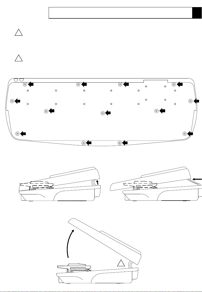
WK4 - WK6 and WK8
Model - Modello Instructions / Istruzioni
ENGLISH
Disconnect the instrument from the mains.
!
Carefully turn the instrument over and unscrew the screws marked by the arrows.
Hold the chassis (top and bottom) tightly and turn the instrument the right way up. Grasp the extreme top
ends of the lid and lift it off by following the sequence of illustrations A, B and C.
ITALIANO
Sconnetti lo strumento dalla presa di corrente.
Rovesciare con attenzione lo strumento e rimuovere le viti indicate dalle frecce.
!
Trattenendo saldamente le parte superiore e inferiore dello strumento raddrizzarlo, afferrare le estremità del
coperchio e sollevarlo seguendo le istruzioni A, B e C.
Front / Davanti
Rear / Dietro
Opening / Apertura
(A) Lift up
Sollevare
(B) Pull towards you to clear the keyboard.
Tiralo verso te per liberarlo dalla tastiera.
(C) Raise the lid, taking care not to disconnect the cables.
Sollevare il coperchio, facendo attenzione a non scollegare i cavi.
!
Mounting Instructions M-3
Page 4
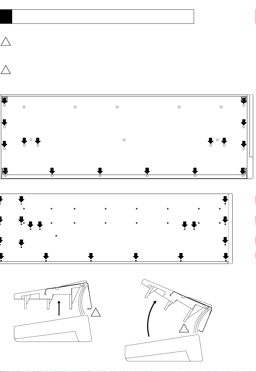
Opening / Apertura SK76-88 and SK760-880
Instructions / Istruzioni
ENGLISH
Disconnect the instrument from the mains.
!
Carefully turn the instrument over and unscrew the screws marked by the arrows.
Hold the chassis (top & Bottom) tightly and turn the instrument the right way up,
lift off the top chassis as shown in the figure with care without forcing or disconnecting the cables.
ITALIANO
Sconnettere lo strumento dalla presa di corrente.
!
Rovesciare con attenzione lo strumento e rimuovere le viti indicate dalle frecce.
Trattenendo saldamente le parti superiore e inferiore raddrizzare lo strumento,
rimuovere la parte superiore come indicato in figura, attenzione a non forzare o scollegare i cavi.
Front / Davanti
Rear / Dietro
Model - Modello
a) Lift up.
Sollevare.
M-4 Mounting Instructions
Rear / Dietro
!
a) Be careful do not disconnect the cables.
Attenzione a non sconnettere i cavi.
!
Page 5
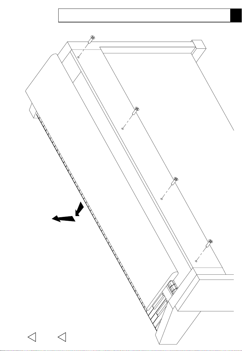
PS2500
Model - Modello
Opening 1/ Apertura 1 ->
Instructions / Istruzioni
ENGLISH
Disconnect the instrument from the mains.
Unscrew the four screws at the rear of instrument.
!
ITALIANO
Sconnettere lo strumento dalla presa di corrente.
Rimuovere le quattro viti sul retro dello strumento.
Remove the top panel in the direction as shown.
Rimuovere il pannello superiore nella direzione indicata.
!
Mounting Instructions M-5
Page 6

PS2500-> Opening 2/ Apertura 2
Instructions / Istruzioni Model - Modello
M-6 Mounting Instructions
Remove the keyboard cover (slide it through the lateral guides).
Rimuovere i due bloccaggi (A) dai laterali.
Remove the two locking plates (A) from the sides.
ENGLISH
Rimuovere il copri tastiera (farlo scorrere attraverso le guide laterali).
ITALIANO
Page 7

Model - Modello
Opening 1/ Apertura 1 ->GPS2500
Instructions / Istruzioni
Rimuovere il pannello di protezione sollevandolo dal retro (B). Svitare le due viti laterali (C).
Sconnettere lo strumento dalla presa di corrente. Sollevare il coperchio e svitare le tre viti (A).
Sollevare la specchiera col copritastiera sollevato.
ITALIANO
Note: to operate without difficulty two people are required.
Remove the protection panel by lifting it from the rear (B). Unscrew the two lateral screws (C).
Disconnect the instrument from the mains. Lift the cover and unscrew the three screws (A).
Lift up the front panel with the keyboard cover raised.
ENGLISH
!
Nota: per operare facilmente sono necessarie due persone.
!
Mounting Instructions M-7
Page 8

-> Opening 2/ Apertura 2
Instructions / Istruzioni
GPS2500
Model - Modello
Unscrew the three screws (A), disconnect the three grounding jumpers (B), pull the controls panel
to disconnect other jumpers of the controls panel, rest the panel temporarily on the keyboard.
To easy access to the internal circuitry, you must remove the controls panel.
toward you and raise it. To install the optional accessories it is not necessary
ENGLISH
Per far ciò svitare le tre viti (A), scollegare i tre rilanci di massa (B), muovere il pannello dei controlli
scollegare gli altri rilanci dal pannello di controllo, appoggiarlo temporaneamente sopra la tastiera.
Per facilitare l’accesso alle parti interne devi rimuovere il pannello dei controlli.
leggermente avanti e in su. Per installare gli accessori opzionali non è necessario
To re-assemble the piano follow the instructions in reverse order.
ITALIANO
Per riassemblare il piano seguire all’indietro le istruzioni.
M-8 Mounting Instructions
Page 9

WK4, WK6 and WK6 Power Station
Model Instructions
Mounting
NOTE:
set on A position if the buffer
The jumper J1 [F] must be
Leave the jumper J2 on its
modules are intalled.
position if the SIMM dram
modules are installed, on B
position.
(Code 841009)
(Code 841004)
(Code 761143)
(Code 761152)
(Code 761093)
by means of the screw [8].
and to the CPU [A] and amplifier [D] boards.
ENGLISH
KIT 970291 (PAL) - KIT 970292 (NTSC) - A/V Kit with Vocal Processor
- Locate the CPU Board [A] and insert the buffer modules [2] into the connectors [H].
- Fix the AUDIO/VIDEO Board [1] to the threaded locations of the support [B]
- Connect the cable [3] to the CPU board.
and that the jumper J1 [F] is set to position "A".
- Check that the two jumpers J5 e J8 [E] are set to position "A"
- Connect the cables [3-4-5-6-7] to the AUDIO/VIDEO Board [1]
Audio/Video board NTSC
1) Audio/Video board PAL
2) 2 buffer modules
Part List:
(Code 840204)
5) 16 contacts x 7.5cm flat cable
4) 9 contacts x 15cm flat cable
3) 34 contacts x 7.5cm flat cable
Mounting Instructions M-9
(Code 271200)
(Code 955990)
(Code 130317)
(Code 840823)
(Code 120003)
(Code 841025)
(Code 130428)
11) Vocal Processor Owner’s Manual
10) Vocal Processor Demo Disk
Video Cable NTSC (Din to Rca)
9) Video Cable PAL (Din to Scart)
6) 10 contacts x 10cm flat cable
7) 2 contacts x 10cm cable
8) 4 screws (M3x8)
Page 10

(Cod. 841004)
3) Cavo piatto 34 contatti 7.5cm
12) Disco sistema operativo WK4
9) Cavo Video PAL (Din / Scart)
Cavo Video NTSC (Din / Rca)
10) Disco Demo Vocal Processor
11) Manuale Utente Vocal Processor
7) Cavo schermato 2 contatti 10cm
6) Cavo piatto 10 contatti 10cm
5) Cavo piatto 16 contatti 7.5cm
4) Cavo piatto 9 contatti 15cm
8) 4 viti (M3x8)
(Cod. 271200)
(Cod. 955991)
(Cod. 840823)
(Cod. 955990)
(Cod. 130428)
(Cod. 130317)
(Cod. 120003)
(Cod. 841025)
(Cod. 841009)
(Cod. 840204)
NOTE:
nella posizione A se sono installati
Lasciare il ponticello J2 nella sua
posizione.
i moduli buffer, nella posizione B se
sono installati i moduli Dram SIMM.
Il ponticello J1 [F] deve essere
KIT 970291 (PAL) - KIT 970292 (NTSC) - Kit A/V con Vocal Processor
- Trovare la scheda CPU [A] e inserire i moduli buffer [2] nei connettori [H].
- Collegare il cavo [3] alla scheda CPU.
- Fissare la scheda AUDIO/VIDEO [1] agli inserti filettati sul supporto [B]
- Collegare con i cavi [3-4-5-6-7] la scheda AUDIO/VIDEO [1]
alla scheda CPU [A] e alla scheda Amplificatore [D].
- Controllare che i due ponticelli J5 e J6 [E] siano in posizione "A"
e che il ponticello J1 [F] sia in posizione "A".
Scheda Audio/Video NTSC
1) Scheda Audio/Video PAL
Lista Parti:
tramite le viti [8].
2) 2 moduli buffer
(Cod. 761143)
(Cod. 761152)
(Cod. 761093)
Istruzioni
Montaggio
ITALIANO
Modello
WK4, WK6 e WK6 Power Station
NOTA: per WK6 e WK6 Power Station usare il disco di sistema operativo fornito con la tastiera.
Page 11

GPS2500 and PS2500
Model
Mounting
Instructions
Leave the jumper J2 on
its position.
modules are intalled.
position if the SIMM dram
modules are installed, on B
set on A position if the buffer
The jumper J1 [F] must be
NOTE:
(761152)
(761093)
(840204)
(841049)
(841009)
(841004)
(761143)
by means of the screw [8].
and to the CPU [A] and amplifier [D] boards.
ENGLISH
KIT 970291 (PAL) - KIT 970292 (NTSC) - A/V Kit with Vocal Processor
- Locate the CPU Board [A] and insert the buffer modules [2] into the connectors [H].
- Fix the AUDIO/VIDEO Board [1] to the threaded locations of the support [B]
- Connect the cable [3] to the CPU board.
and that the jumper J1 [F] is set to position "A".
- Check that the two jumpers JP1 e JP2 [E] are set to position "A"
- Connect the cables [3-4-5-6-7] to the AUDIO/VIDEO Board [1]
1) Audio/Video board PAL
Part List:
2) 2 buffer modules
5) 16 contacts x 7.5cm flat cable
Audio/Video board NTSC
6) 10 contacts x 40cm flat cable
4) 9 contacts x 15cm flat cable
3) 34 contacts x 7.5cm flat cable
Mounting Instructions M-11
(120003)
(130428)
(955990)
(271200)
(130317)
(841025)
8) 4 screws (M3x8)
7) 2 contacts x 10cm cable
10 contacts x 65cm flat cable (841019)
11) Vocal Proc. Owner’s Manual
10) Vocal Proc. Demo Disk
Video Cable NTSC (Din to Rca)
9) Video Cable PAL (Din to Scart)
Page 12

(840204)4) Cavo piatto 9 contatti 15cm
(841019) Cavo piatto 10 contatti 65cm
(271200)
(955994)
(130317)
(955990)
(130428)
(120003)
(841025)
(841009)
(841049)
5) Cavo piatto 16 contatti 7.5cm
6) Cavo piatto 10 contatti 40cm
7) Cavo schermato 2 contatti 10cm
8) 4 viti (M3x8)
9) Cavo Video PAL (Din / Scart)
Cavo Video NTSC (Din / Rca)
10) Disco Demo Vocal Processor
12) Disco Sistema Op. PS-GPS
11) Manuale Utente Vocal Proc.
nella posizione A se sono installati
Lasciare il ponticello J2 nella sua
i moduli buffer, nella posizione B se
sono installati i moduli Dram SIMM.
Il ponticello J1 [F] deve essere
NOTE:
posizione.
KIT 970291 (PAL) - KIT 970292 (NTSC) - Kit A/V con Vocal Processor
Lista Parti:
(761093)
(761152)
(841004)
(761143)
1) Scheda Audio/Video PAL
Scheda Audio/Video NTSC
2) 2 moduli buffer
3) Cavo piatto 34 contatti 7.5cm
- Trovare la scheda CPU [A] e inserire i moduli buffer [2] nei connettori [H].
- Fissare la scheda AUDIO/VIDEO [1] agli inserti filettati sul supporto [B]
- Collegare con i cavi [3-4-5-6-7] la scheda AUDIO/VIDEO [1]
- Controllare che i due ponticelli JP1 e JP2 [E] siano in posizione "A"
- Collegare il cavo [3] alla scheda CPU.
tramite le viti [8].
alla scheda CPU [A] e alla scheda Amplificatore [D].
e che il ponticello J1 [F] sia in posizione "A".
ITALIANO
GPS2500 and PS2500
Istruzioni
Montaggio
Modello
Page 13

SK76-SK88
Model
Mounting
Instructions
Leave the jumper J2 on its
position.
intalled.
SIMM dram modules are
NOTE:
are installed, on B position if the
on A position if the buffer modules
The jumper J1 [F] must be set
(120003)
(130428)
(955990)
(955992)
(271200)
(130317)
(841025)
(841049)
(761152)
(761143)
KIT 970291 (PAL) - KIT 970292 (NTSC) - A/V Kit with Vocal Processor
ENGLISH
by means of the screw [8].
- Locate the CPU Board [A] and insert the buffer modules [2] into the connectors [H].
- Fix the AUDIO/VIDEO Board [1] to the threaded locations of the support [B]
- Connect the cable [3] to the CPU board.
and that the jumper J1 [F] is set to position "A".
and to the CPU [A] and amplifier [D] boards.
- Check that the two jumpers JP1 e JP2 [E] are set to position "A"
- Connect the cables [3-4-5-6-7] to the AUDIO/VIDEO Board [1]
Audio/Video board NTSC
1) Audio/Video board PAL
Part List:
(841009)
(761093)
(840204)
(841004)
5) 16 contacts x 7.5cm flat cable
6) 10 contacts x 40cm flat cable
7) 2 contacts x 10cm cable
4) 9 contacts x 15cm flat cable
3) 34 contacts x 7.5cm flat cable
2) 2 buffer modules
8) 4 screws (M3x8)
11) Vocal Processor Owner’s Manual
10) Vocal Processor Demo Disk
Video Cable NTSC (Din to Rca)
9) Video Cable PAL (Din to Scart)
12) SK76 Operating System Disk
Mounting Instructions M-13
(955993)
SK88 Operating System Disk
Page 14

KIT 970291 (PAL) - KIT 970292 (NTSC) - Kit A/V con Vocal Processor
Disco Sistema Operativo SK88
5) Cavo piatto 16 contatti 7.5cm
11) Manuale Utente Vocal Processor
12) Disco Sistema Operativo SK76
10) Disco Demo Vocal Processor
Cavo Video NTSC (Din / Rca)
9) Cavo Video PAL (Din / Scart)
6) Cavo piatto 10 contatti 40cm
7) Cavo schermato 2 contatti 10cm
Scheda Audio/Video NTSC
4) Cavo piatto 9 contatti 15cm
1) Scheda Audio/Video PAL
3) Cavo piatto 34 contatti 7.5cm
- Trovare la scheda CPU [A] e inserire i moduli buffer [2] nei connettori [H].
e che il ponticello J1 [F] sia in posizione "A".
alla scheda CPU [A] e alla scheda Amplificatore [D].
- Controllare che i due ponticelli JP1 e JP2 [E] siano in posizione "A"
- Fissare la scheda AUDIO/VIDEO [1] agli inserti filettati sul supporto [B]
- Collegare con i cavi [3-4-5-6-7] la scheda AUDIO/VIDEO [1]
- Collegare il cavo [3] alla scheda CPU.
2) 2 moduli buffer
8) 4 viti (M3x8)
Lista Parti:
tramite le viti [8].
(955990)
(955993)
(955992)
(271200)
NOTE:
nella posizione A se sono installati
Lasciare il ponticello J2 nella sua
posizione.
i moduli buffer, nella posizione B se
sono installati i moduli Dram SIMM.
Il ponticello J1 [F] deve essere
(761152)
(120003)
(130428)
(130317)
(761093)
(840204)
(841025)
(841049)
(841009)
(841004)
(761143)
SK76-SK88Montaggio
Istruzioni
ITALIANO
Model
Page 15

SK760-SK880
Model
Mounting
Instructions
Leave the jumper J2 on its
position.
intalled.
SIMM dram modules are
The jumper J1 [F] must be set
on A position if the buffer modules
are installed, on B position if the
NOTE:
(761143)
by means of the screw [8].
and to the CPU [A] and amplifier [D] boards.
KIT 970291 (PAL) - KIT 970292 (NTSC) - A/V Kit with Vocal Processor
ENGLISH
- Connect the cable [3] to the CPU board.
- Fix the AUDIO/VIDEO Board [1] to the threaded locations of the support [B]
- Locate the CPU Board [A] and insert the buffer modules [2] into the connectors [H].
and that the jumper J1 [F] is set to position "A".
- Connect the cables [3-4-5-6-7] to the AUDIO/VIDEO Board [1]
- Check that the two jumpers JP1 e JP2 [E] are set to position "A"
1) Audio/Video board PAL
Part List:
(840204)
(841004)
(761093)
(761152)
Audio/Video board NTSC
(841009)
(841049)
2) 2 buffer modules
3) 34 contacts x 7.5cm flat cable
4) 9 contacts x 15cm flat cable
6) 10 contacts x 40cm flat cable
5) 16 contacts x 7.5cm flat cable
(130428)
(841025)
(130317)
(120003)
8) 4 screws (M3x8)
7) 2 contacts x 10cm cable
9) Video Cable PAL (Din to Scart)
Video Cable NTSC (Din to Rca)
(271200)
(955990)
10) Vocal Processor Demo Disk
NOTE: the system disk is already supplied with
11) Vocal Processor Owner’s Manual
the keyboard.
Mounting Instructions M-15
Locate the jumpers [E] accordingly with the code shown on the label sticked to the board: * 730668 **731020
Page 16

- Collegare il cavo [3] alla scheda CPU.
- Collegare con i cavi [3-4-5-6-7] la scheda AUDIO/VIDEO [1]
- Fissare la scheda AUDIO/VIDEO [1] agli inserti filettati sul supporto [B]
- Controllare che i due ponticelli JP1 e JP2 [E] siano in posizione "A"
alla scheda CPU [A] e alla scheda Amplificatore [D].
e che il ponticello J1 [F] sia in posizione "A".
- Trovare la scheda CPU [A] e inserire i moduli buffer [2] nei connettori [H].
KIT 970291 (PAL) - KIT 970292 (NTSC) - Kit A/V con Vocal Processor
tramite le viti [8].
ITALIANO
2) 2 moduli buffer
3) Cavo piatto 34 contatti 7.5cm
1) Scheda Audio/Video PAL
4) Cavo piatto 9 contatti 15cm
Scheda Audio/Video NTSC
7) Cavo schermato 2 contatti 10cm
6) Cavo piatto 10 contatti 40cm
9) Cavo Video PAL (Din / Scart)
Cavo Video NTSC (Din / Rca)
10) Disco Demo Vocal Processor
11) Manuale Utente Vocal Processor
5) Cavo piatto 16 contatti 7.5cm
Lista Parti:
8) 4 viti (M3x8)
(761143)
(841004)
(840204)
(761093)
(761152)
(841009)
(841049)
(841025)
(130317)
(130428)
(120003)
(271200)
(955990)
nella posizione A se sono installati
Il ponticello J1 [F] deve essere
NOTE:
Istruzioni
Montaggio
Model
SK760-SK880
sono installati i moduli Dram SIMM.
i moduli buffer, nella posizione B se
Lasciare il ponticello J2 nella sua
posizione.
NOTA: il disco di sistema è già fornito con
la tastiera.
Localizzare i ponticelli [E] secondo il codice stampato sull’etichetta applicata alla scheda: *730668 **731020
 Loading...