

Peavey VSX 26e, VSX 48e Operating Manual
VSX™ 26e and VSX™ 48e
Digital Loudspeaker
Processors
Operating
Manual
www.peavey.com

FCC/ICES Compliancy Statement
This device complies with Part 15 of the FCC rules and Industry Canada license-exempt RSS Standard(s). Operation is
subject to the following two conditions: (1) this device may not cause harmful interference, and (2) this device must
accept any interference received, that may cause undesired operation.
Le présent appareil est conforme aux CNR d’lndustrie Canada applicables aux appareils radio exempts de
licence. L’exploitation est autorisée aux deux conditions suivantes: (1) I’appareil ne doit pas produire de
brouillage, et (2) I’utilisateur de I’appareil doit accepter tout brouillage radioélectrique subi, même si le
brouillage est susceptible d’en compromettre le fonctionnement.
Warning: Changes or modifications to the equipment not approved by Peavey Electronics Corp. can void the
user’s authority to use the equipment.
Note – This equipment has been tested and found to comply with the limits for a Class B digital device,
pursuant to Part 15 of the FCC Rules. These limits are designed to provide reasonable protection against
harmful interference in a residential installation. This equipment generates, uses, and can radiate radio
frequency energy and, if not installed and used in accordance with the instructions, may cause harmful
interference to radio communications. However, there is no guarantee that interference will not occur in a
particular installation. If this equipment does cause harmful interference to radio or television reception,
which can be determined by turning the equipment off and on, the user is encouraged to try and correct the
interference by one or more of the following measures.
• Reorient or relocate the receiving antenna.
• Increase the separation between the equipment and receiver.
• Connect the equipment into an outlet on a circuit different from that to which the receiver is
connected.
• Consult the dealer or an experienced radio/TV technician for help.
Caution
The equipment complies with FCC radiation exposure limits set forth for an uncontrolled
environment.
2

ENGLISH
VSX™ 26e and VSX™ 48e
Digital Loudspeaker Processors
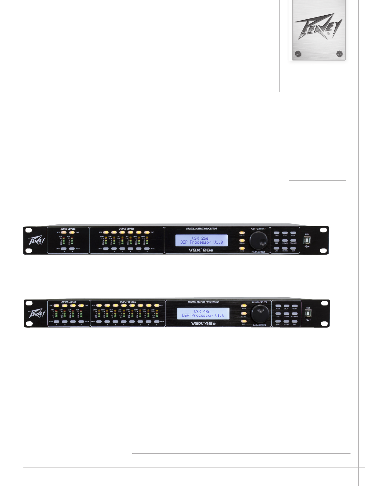
The VSXe processors are DSP-based, loudspeaker management systems that boast a 96kHz sample rate and a floating point DSP processor for
quiet accurate filter response. The crossover filters are fully adjustable and any input can be routed to any output. The VSX® Editor Program for PC
allows complete remote setup and operation via the front panel USB port or by the rear panel Ethernet network connection. Files can also be saved
and loaded using this interface software.
This manual covers both the VSX 26e and VSX 48e DSP processors. The units are essentially identical except for the number of inputs and outputs.
Please read this guide carefully to ensure your personal safety as well as the safety of your equipment.
Features
• Balanced Inputs: VSX 26e 2, VSX 48e 4
• Balanced Outputs: VSX 26e 6, VSX 48e 8
• 96 kHz Sample rate
• 24 bit Delta-Sigma A/D and D/A converters
• Dynamic range input to output greater than 109 dB (A-weighted) or 107 dB (unweighted)
• Every input features Gain, Mute, HP and LP filters, 8 bands of PEQ, polarity and Delay (680 mS),
• Every output features: 9 bands of PEQ, gain, compressor/limiter, polarity, Delay (680 mS), mute, and crossover/band-pass filters
• EQ filter types include: PEQ, Low-Shelf, Hi-Shelf, Low-Pass, High-Pass, All-Pass1 and All-Pass2.
• Crossover/Band-pass filters feature Butterworth, Bessel or Linkwitz-Riley alignments from 1st order (6 dB/Oct) to 8th order (48 dB/Oct).
• Signal generator (sine, white noise, pink noise).
• Channels can be linked for simplified stereo operation.
• 5 segment LED meters on each input
• 5 segment LED meters with limit indication on each output
• 2 XLR balanced inputs and 6 XLR balanced outputs VSXe 26
• 4 XLR balanced inputs and 8 XLR balanced outputs VSXe 48
• Maximum input and output level +20 dBu, XLR balanced inputs and outputs.
• Frequency response 20 Hz to 20 kHz +0, -1 dB
• THD+N < 0.01% at 1 kHz.
• Security lock
• USB B port for setup and control
• Ethernet port for setup and control.
• Dimensions (HxWxD) 1.75" x 19" x 8" / 45mm x 480mm x 20.5mm
• Weight 5.2 lbs /2.88 kg
• PC Editor Programs allow complete remote setup and operation via USB or Ethernet.
NOTE: The VSX processors can be setup and operated both from the front panel and from the VSX Editor running on a PC. The
PC can be connected to the VSX via USB or Ethernet.
3
Front Panel
6
6 5 4 3 2
5 4 3 2
10
10
9
9
8
8
7
7
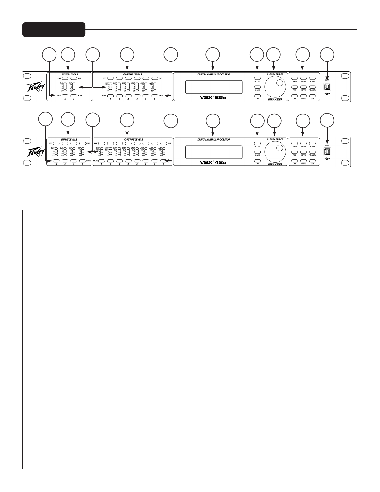
(1) USB port
The USB "B" connector is used to connect a host computer for editing and control using the VSX Editor Program.
1
1
(2) Process Function Buttons
The process-function buttons are used to select a process for editing. Lighted buttons illuminate to indicate they are available
selections. The available functions are different when an input, output or system mode (no input or output selected) for editing.
GAIN: Used to access channel gain controls
Delay: Used to access channel Delay controls
COMP: Available only for output editing, used to access channel compressor/limiter controls.
PEQ: Used to access channel equalization controls
Xover: Used to access the low-pass filter and high-pass filter controls.
POLARITY: Used to access channel polarity normal or invert controls
MATRIX: Available only for output editing, used to route inputs to outputs.
EXIT: Exit channel editing.
(3) Parameter Knob
The parameter knob is used by pressing and rotating to edit processing parameters.
(4) System Function Buttons
Utility: Utility functions include setting Unit ID#, IP address, Security Lock and password, input signal or signal generator,
copy channel and Delay units.
Recall: Used to load saved system presets.
Save: Used to save system presets.
4
(5) LCD Display
Used in conjunction with the front panel controls to edit processing parameters.
(6) Output Mute Buttons
Pressing the mute button alternately mutes and un-mutes the corresponding output. The button lights red when muted.
(7) Output Edit Buttons
Press this button to begin editing processes for the selected output. The specific process to edit can be selected using the process-function
buttons on the right.
(8) Input/Output Monitoring:
Input: The 5 segment LED meters indicate the input signal level with the top Clip LED illuminating before the onset of
clipping. Although you will want to avoid clipping, you will achieve best performance if the 0 LED lights frequently during
loud passages.
Output: The top LED illuminates to indicate the signal has reached the threshold set in the compressor/limiter and that gain
reduction is occurring. The bottom 4 LEDs form the output level meters indicating signal level. The Clip LED illuminates
before the onset of clipping. Although you will want to avoid clipping, you will achieve best performance if the 0 LED flashes
frequently during loud passages.
(9) Input Edit Buttons
Press this button to begin editing processes for the selected input. The specific process to edit can be selected using the process-function
buttons on the right.
(10) Input Mute Buttons
Pressing the mute button alternately mutes and un-mutes the corresponding input. The button lights red when muted.
Rear Panel
11
11 12 13 15 16
12 13
14
15 16
14
5
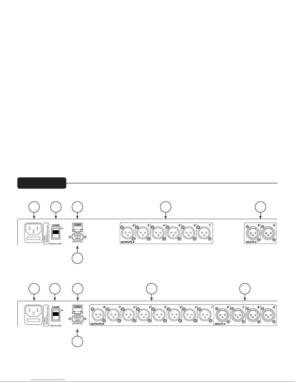
(11) IEC POWER CORD CONNECTION and Fuse Holder
This receptacle is for the IEC line cord (supplied) that provides AC power to the unit. It is very important that you ensure the unit
has the proper AC line voltage supplied.
Please read this guide carefully to ensure your personal safety as well as the safety of your equipment. Never break off the ground pin
on any equipment. It is provided for your safety. If the outlet used does not have a ground pin, a suitable grounding adapter should
be used and the third wire should be grounded properly. To prevent the risk of shock or fire hazard, always be sure that the mixer
and all other associated equipment are properly grounded.
Caution: For 195 to 240 VAC operation, a “F2AL 250V” fuse rated at 2 amps should be used.
(12) ON-OFF SWITCH
This rocker switch supplies AC power to the unit when switched to the ON position. The ON position is with the top side of the
switch pushed “in” or nearly flush with the rear panel.
(13) Ethernet Control Interface
Ethernet port for control of the VSX using the graphical user interface.
(14) D sub 9 connector
Connection for RS232 and RS485 serial control.
(15) OUTPUTS
XLR balanced outputs 1-6 or 1-8.
(16) INPUTS
XLR balanced inputs A and B or A, B, C and C.
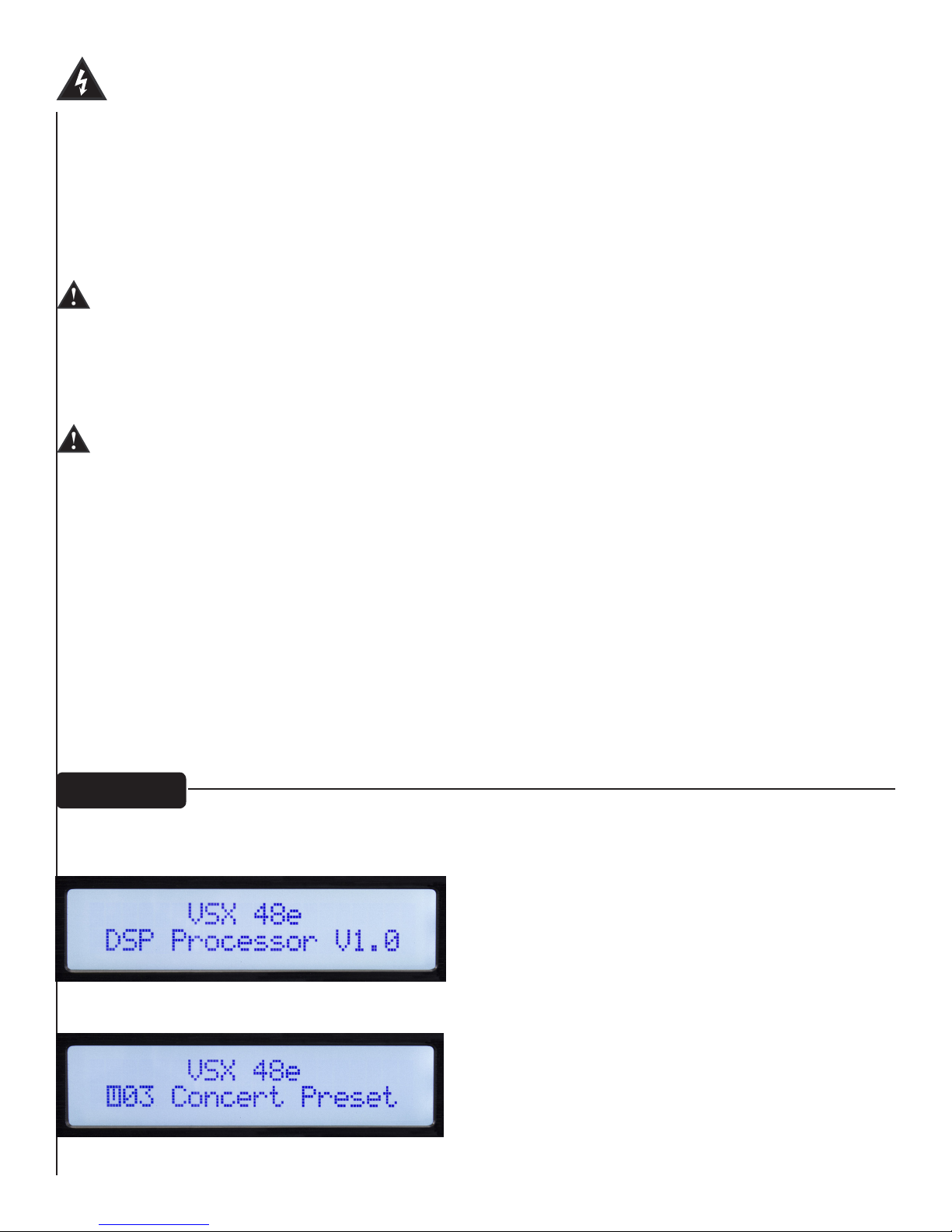
Operation
Operating the VSX processors from the front panel is made simple by a wide array of buttons and a simple
intuitive interface.
Opening screen shows product name and firmware version.
After a brief time out, the currently active preset is displayed.
6
Global Functions: Utility, Recall and Save
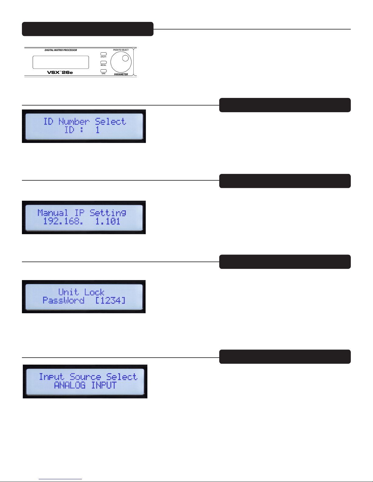
Pressing the utility button opens the screens for system wide settings. Each press of the utility button advances
to the next screen in the sequence. You can press the "Exit" button at any time to return to the main screen.
Device ID #: (Utility Button)
The ID number of the unit can be set in this screen. The ID is used with the Editor program to identify this
unit when multiple units are connected. Each unit must have a unique identifier. It is most important when
units are connected together using the RS 485 serial interface. See the section on serial communication for
more details.
Ethernet Address: (Utility Button)
Set the Ethernet, IP address here for connection to the Editor program using the Ethernet port. Make sure to
note the new address if you edit address!
Security Lock: (Utility Button)
Once on this screen, the parameter knob is used to set the password. Press to advance and rotate to change
each digit. A "Y" or "N" will appear allowing to engage the lock "Y" or turn it off "N".
Input Source Select: (Utility Button)
During normal operation, the analog inputs on the rear of the VSX are routed to the outputs. However, the
VSX has an internal signal generator that can be used for setup and testing. Rotating the parameter knob allows
you to select Analog Input, Pink Noise, White Noise or a Sine-Wave as the input source for all inputs. The
new selection will blink on the screen. Press the Parameter knob to select. You may wish to mute outputs that
you do not wish to receive the signal from the generator. Analog input must be selected for those inputs to
function.
7
 Loading...