


Net2
19/11/2012
0 V
0 V
12V
1 redaeR
:noituaC ylno sredaer CD V21 roF
2 red
aeR
.
stupnI
tputsuO
rewoP
0V
repmaT/USP
tcatnoC
no
ttu
B
ti
x
E
2 yaleR
1 yaleR
Expansion
Port 1Port 2Port 3Port 4
Port 5
Rx
Tx
RS485 Network
CAT5 Cable Coding
nrG
/thW
eraps ro neercS
atad morf seroc
elbac
n
ee
rG
gnrO/th
W
egnarO
10/100 Ethernet
Server Connected
Server Link
100
10
End of Line Termination
ON
OFF
Net2 plus
Intruder Alarm
Set
V0
mrA
sn
S
MOC
.O.N
LABEL HERE
LABEL HERE
http://paxton.info/107
123456
00-01-02-03-04-05
2345612
INPUT AC 100-240V
50 / 60 Hz
1.2A
OUTPUT DC 13.8V 2A
Ins-30200 Net2 Entry - Control unit
Paxton
Technical Support
01273 811011 support@paxton.co.uk
Technical help is available: Monday - Friday from 07:00 - 19:00 (GMT)
Saturday from 09:00 - 13:00 (GMT)
Documentation on all Paxton products can be found on our website - http://www.paxton.co.uk/
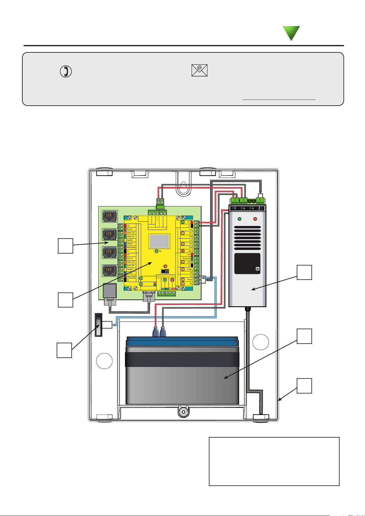
Description of product
The Net2 Entry control unit is the central interface between a panel and the door and provides data and PoE power
for the monitors. The ports can also be used to expand the network of panels and monitors through Net2 Entry
extension switches or to connect the control unit to a Net2 system running Net2 v4.25 or later.
1
4
2
3
5
6
1. PoE Switch ( 4 PoE + 1 standard port )
Paxton recommend that the network cable is run
to each location and terminated in a network box.
A patch cable should then be used to link the unit
to the network. This makes unit replacement or
removal for building maintenance much easier.
2. Net2 plus control unit
3. Tamper switch
4. 2A 12V DC power supply
5. Battery backup ( not supplied )
6. Plastic cabinet
Installation
Connect the entry panel to the control unit using the network cabling. Connect the monitor(s) to the control unit.
Further devices may easily be added as required in the future.
Power up the control unit.
The Net2 Entry panel and monitor(s) will power up using the PoE provided by the control unit.
Net2 hardware and software
The access control function is administered by the Net2 system.
The installation of Net2 hardware and software is fully described in the Net2 documentation supplied with this unit
and also on the website as follows:
XIns-30080 - Net2 plus control unit < http://paxton.info/924 >
XAN1127 - Net2 Entry - Planning and installation < http://paxton.info/1896 >
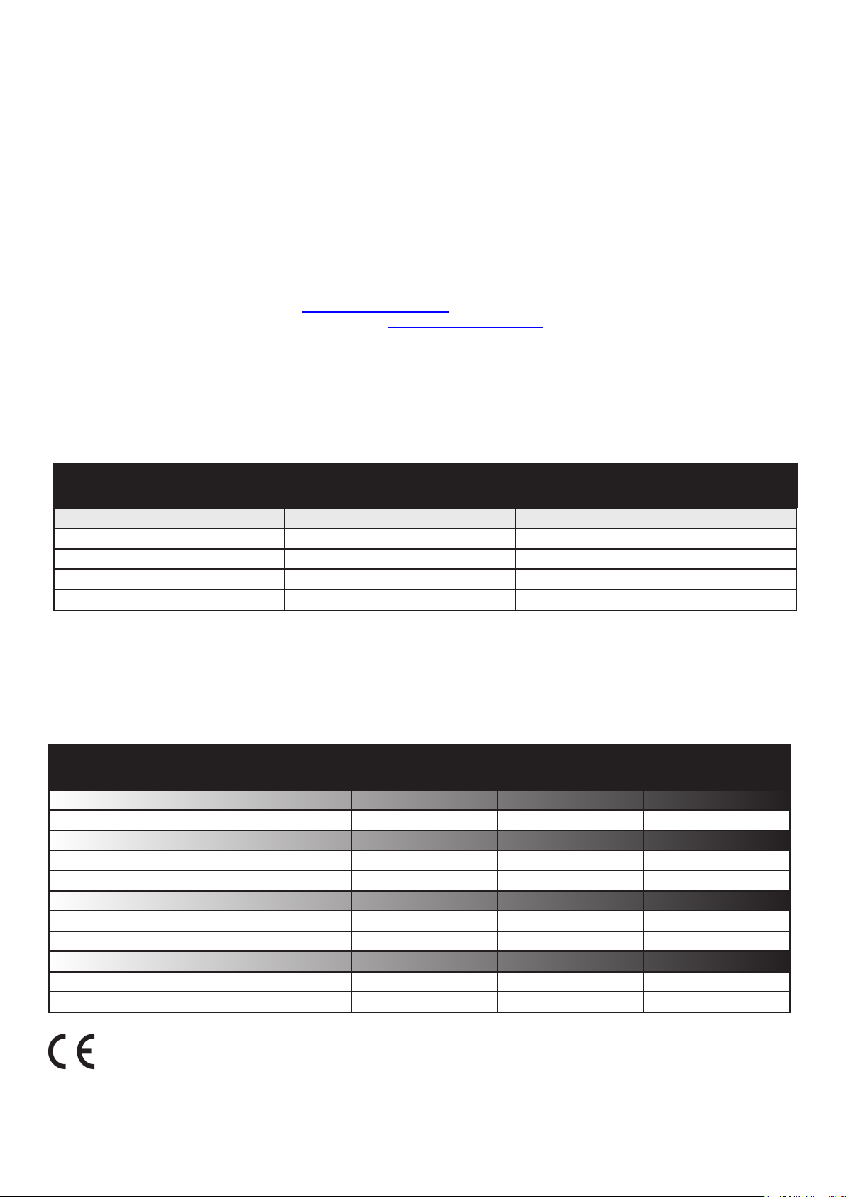
Lock power considerations
The power required for the lock will limit the number of Net2 Entry devices that this control board will support.
Each control board has four network ports that can also provide PoE. The following table shows the devices that
can be supported by a Net2 Entry control unit depending on the power required for the lock.
Resource Distribution
Lock power required
up to 650 mA
up to 500 mA
up to 350 mA
up to 200 mA
The additional network connections are available to link to the Net2 PC server, other Net2 Entry control units or
network switch units to expand the system. These do not require PoE power.
If additional equipment (Exit button, internal reader/keypad, etc.) is to be tted, this must be included in the Lock
power requirement.
PoE powered devices
1 Panel only
1 Panel + 1 Monitor
1 Panel + 2 Monitors
1 Panel + 3 Monitors
Additional network connections
3
2
1
0
Specications
Dimensions
Electrical
PSU output voltage
PSU output current
Features
PoE network ports
Standard network ports
Environment
Operating temperature
IP Rating
Width
236 mm 320 mm 80 mm
Min
Min
Min
0 °C 45 °C
Height
Max
12v DC
2A
Max
4
1
Max
Depth
IEEE 802.3af
Net2 plus port
Indoor use only
This equipment has been tested and found to comply with the limits for a Class A digital device,
pursuant to the standard EN55022, when using UTP (unshielded twisted pair) category cable. In order
to comply with the limits for a Class B digital device it is necessary to use FTP (foiled twisted pair) or
STP (shielded twisted pair) category cable on the PoE/network ports.
 Loading...