


Users Manual
Model 656 / 636
PAXAR Systems Group
Manual Edition 3.0
18 February 2002
Manual Part Number 351398
This page intentionally blank
ii • |
Users Manual Model 656/636 |
Contents
Scope |
1 |
Introduction ............................................................................................................................... |
1 |
Safety Issues / Warnings |
1 |
Caution ...................................................................................................................................... |
1 |
Warranty Information |
2 |
Customer Responsibility |
3 |
Location of Printer..................................................................................................................... |
3 |
AC Power Line .......................................................................................................................... |
4 |
Unpacking.................................................................................................................................. |
4 |
Inventory of Components .......................................................................................................... |
5 |
Printer Setup |
6 |
Installing the Stacker ................................................................................................................. |
6 |
Fuse Configuration .................................................................................................................... |
7 |
P.C. Board Installation............................................................................................................... |
7 |
TCB Dip Switch S2 Settings ..................................................................................................... |
8 |
Installing the Power Cord .......................................................................................................... |
8 |
Installing the PC Interface Cable............................................................................................... |
9 |
Installing the PC Software......................................................................................................... |
9 |
Product Description |
10 |
Printer Description................................................................................................................... |
10 |
Personal Computer Specifications........................................................................................... |
11 |
Unit Specification .................................................................................................................... |
11 |
Printer Operation |
13 |
Installing Ink Ribbon ............................................................................................................... |
13 |
Loading Stock.......................................................................................................................... |
14 |
Butt Splice ............................................................................................................................... |
15 |
Web Guide Adjustment ........................................................................................................... |
15 |
Print Head Open / Close .......................................................................................................... |
16 |
Control Panel Operation |
17 |
Printer Controls........................................................................................................................ |
17 |
Indicator Lights........................................................................................................................ |
19 |
Front Panel Menu Functions.................................................................................................... |
20 |
Users Manual Model 656/636 |
• iii |
LCD Display............................................................................................................................ |
21 |
Display Modes ......................................................................................................................... |
23 |
Maintenance / Adjustments |
29 |
Print Head Handling ................................................................................................................ |
29 |
Print Head Cleaning................................................................................................................. |
30 |
Print Head Replacement .......................................................................................................... |
31 |
Print Head Adjustment............................................................................................................. |
32 |
Registration Sensor Adjustment .............................................................................................. |
33 |
Stock out Adjustment............................................................................................................... |
37 |
Knife Square Adjustment......................................................................................................... |
37 |
Stacker Adjustments ................................................................................................................ |
38 |
Stock Feed Adjustment............................................................................................................ |
38 |
Mechanical Adjustment Of Feed Roller Pressure (Blue Roller).............................................. |
39 |
Mechanical Adjustment of Stock Sense - Mark Light Receiver.............................................. |
39 |
Electrical Connections |
41 |
Machine Wiring ....................................................................................................................... |
41 |
Relay Assembly ....................................................................................................................... |
42 |
Electrical System Schematic.................................................................................................... |
43 |
Motherboard Power Connectors .............................................................................................. |
44 |
Electrical Trouble Shooting |
45 |
Power Up / Sign On / Communications................................................................................... |
45 |
Stock / Ink Advance................................................................................................................. |
47 |
Print ......................................................................................................................................... |
49 |
Cut / Stack................................................................................................................................ |
51 |
Electrical Trouble Shooting / Machine Set Up Sequence........................................................ |
52 |
Mechanical Trouble Shooting |
53 |
Stock ........................................................................................................................................ |
53 |
Ink............................................................................................................................................ |
55 |
Print ......................................................................................................................................... |
56 |
Knife ........................................................................................................................................ |
57 |
Mechanical Trouble Shooting Sequence ................................................................................. |
59 |
Lubrication Procedure ............................................................................................................. |
59 |
Appendix A |
60 |
Error Messages ........................................................................................................................ |
60 |
Appendix B |
61 |
Software Upgrade Chip Placement Positions .......................................................................... |
61 |
Appendix C |
64 |
Ink and Stock Transfer Types.................................................................................................. |
64 |
Appendix D |
67 |
Knife MFG Guideline.............................................................................................................. |
67 |
iv • |
Users Manual Model 656/636 |
Assembly Drawings |
71 |
Unwind Assembly Drawing .................................................................................................... |
72 |
Unwind Parts List .................................................................................................................... |
73 |
Web Guide / Light Bar Assembly Drawing............................................................................. |
74 |
Web Guide / Light Bar Parts List ............................................................................................ |
75 |
Drive Assembly Drawing ........................................................................................................ |
76 |
Drive Parts List........................................................................................................................ |
77 |
Printhead Assembly Drawing .................................................................................................. |
78 |
Printhead Parts List.................................................................................................................. |
79 |
Ink Unwind / Rewind Assembly.............................................................................................. |
80 |
Ink Unwind / Rewind Parts List .............................................................................................. |
81 |
Ink Rewind Arbor Assembly................................................................................................... |
82 |
Ink Rewind Arbor Parts List.................................................................................................... |
83 |
Feed & Ink Drive Assembly.................................................................................................... |
84 |
Feed & Ink Drive Parts List..................................................................................................... |
85 |
Timing Belt Threading Diagram.............................................................................................. |
86 |
Timing Belt Parts List.............................................................................................................. |
87 |
Ink Turn Roller Assembly ....................................................................................................... |
88 |
Ink Turn Roller Parts List........................................................................................................ |
89 |
Knife Assembly Drawing ........................................................................................................ |
90 |
Knife Parts List........................................................................................................................ |
91 |
Stacker Assembly Drawing ..................................................................................................... |
92 |
Stacker Parts List ..................................................................................................................... |
93 |
Rewind Assembly Drawing..................................................................................................... |
94 |
Rewind Parts List..................................................................................................................... |
95 |
Stock Out Sensor Assembly Drawing ..................................................................................... |
96 |
Stock Out Sensor Parts List ..................................................................................................... |
97 |
Optional Stackers |
98 |
4.25” Stacker Specifications.................................................................................................... |
99 |
Optional 4.25” Pick-up Assembly ......................................................................................... |
100 |
Optional 4.25” Pick-up Parts List.......................................................................................... |
101 |
Optional 4.25” Stacker Assembly.......................................................................................... |
102 |
Optional 4.25” Stacker Parts List .......................................................................................... |
103 |
Optional Down Stacker Assembly Drawing (Part 1)............................................................. |
104 |
Optional Down Stacker Parts List (Part 1) ............................................................................ |
105 |
Optional Down Stacker Assembly Drawing (Part 2)............................................................. |
106 |
Optional Down Stacker Parts List (Part 2) ............................................................................ |
107 |
Optional Down Stacker Assembly Drawing (Part 3)............................................................. |
108 |
Optional Down Stacker Parts List (Part 3) ........................................................................... |
109 |
Users Manual Model 656/636 |
• v |

Scope
Introduction
This user manual was arranged for the person who is going to operate this machine. The information is arranged in the order that is needed to install and operate the machine. It starts with general information, then to unpacking the carton, installing the ink ribbon and stock, printer operation, control panel operation, and finally care and maintenance of the unit.
We at PAXAR hope that you will come to appreciate the efforts and quality which have gone into producing your PAXAR 656 / 636 Printer and wish to remind you that you are our number one priority. We welcome any constructive comments or criticisms so that we may continue to offer you the best printer in the industry for years to come.
Safety Issues / Warnings
Caution
This machine has some pinch points. All of these areas have been well guarded and it is recommended that the safety features of this machine are never altered or defeated.
Users Manual Model 656/636 |
Scope • 1 |
Warranty Information
Limited Warranty
PAXAR Systems Group, Division of PAXAR Corporation, extends the following warranties to the original purchaser of a PAXAR 656 / 636 which has been installed and operated using recommended procedures and operating conditions.
Parts
Parts found defective in material or workmanship will be replaced at no charge for a period of six months following the machine's shipment date. Parts damaged by negligence, abuse, or normal wear are not covered. PAXAR 656 / 636 parts classed as normal wear items include print heads, feed and platen rollers, and knife blades.
Service
Service to replace defective parts as defined above, shall be provided at no charge for a period of six months following the shipment date.
When ordering machines and supplies in the U.S.A., reference all correspondence to the address below.
PAXAR Corporation
One Wilcox Street
Sayre, Pa. 18840
Call: 1-800-96PAXAR or (570) 888-6641 Fax: (570) 888-5230
For spare parts, requests for service or technical support Paxar Service Group
170 Monarch Lane Miamisburg, OH 45342
Call: |
(800) 543-6650 |
|
Fax: |
(937) |
865-2092 for Warranty Parts |
Fax: |
(937) |
865-2707 or (937) 865-6605 for Customer Parts Orders |
For parts and service in other countries please contact your local PAXAR supplier.
PAXAR Apparel Identification Systems Group reserves the right to incorporate any modifications or improvements in the machine system and machine specifications which it considers necessary and does not assume any obligation to make said changes in equipment previously sold.
2 • Warranty Information |
Users Manual Model 656/636 |
Customer Responsibility
Location of Printer
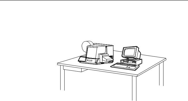
The printer weighs approximately 57 Lbs (~26Kg) and requires a table of sufficient quality and strength to handle this load while the printer is operating. PAXAR recommends an industrial type work table having the approximate dimensions of 96" wide to 30" deep to 32" high. Refer to Figure 1a.
Figure 1a Recommended workstation layout.
The location of the PAXAR 656 / 636 printer should be based on human factors. The printer should be located in an area which maintains optimum flow of your product while providing for the operator’s comfort. PAXAR has taken significant steps to ensure that the operator controls and operations are easily accessible. This goal can only be met, however, if the printer is also located with human factors in mind. These include the height of the printer, the space around the printer, and the accessibility to the printer.
The PAXAR 656 / 636 printer is a high resolution thermal printer. While PAXAR has designed the printer to be reasonably quiet, it is recommended to location the printer in an area where printing and cutting repetitious noise is acceptable.
The unit should always be operated with the cover closed to minimize the amount of dust and dirt in the machine.
Users Manual Model 656/636 |
Customer Responsibility • 3 |

AC Power Line
PAXAR requires that the electric service be 10 Amps @ 110VAC or 10 Amps @ 220VAC. This will allow the computer and any additional support or service equipment to be plugged into the same service.
Any electrical service which is supplying a PAXAR printer or peripheral equipment connected to a PAXAR printer should follow standard electrical code practices including proper grounding and neutral requirements.
The PAXAR printer was designed to operate in an industrial setting for extended period of time; however, the printer is controlled by a microprocessor which is very sensitive to brownouts or power spikes. For this reason as well as the minimum recommended current supply, PAXAR recommends that a separate “clean” service be installed or reserved for the exclusive use of the PAXAR printer and it’s peripherals.
Unpacking
The PAXAR printer is shipped in a large cardboard box which may be difficult to move by hand.
DO NOT REMOVE THE PRINTER FROM THE CRATE OR UNPACK IN THE SHIPPING / RECEIVING DEPARTMENT.
NOTE: Unpacking in the shipping/receiving department is not recommended for the following reasons. First: The cardboard carton in which your PAXAR printer was shipped allows the printer to be moved with a forklift, forkcart or hand cart. Because of the weight of the printer, it is easier and safer to use one of these devices to move the printer to its intended installation location. Second: Leaving the printer in the carton while it is being moved within your facility will help to protect the printer during any movements to this new location. Once the printer has reached its intended location you should begin the unpacking process.
Open the printer from the top of the box (See Figure 1b). Do not cut deep into the carton as there are items located just under the top. Remove the items located on the top insert. Remove the top insert. Lift the printer onto the table with the two banding straps. Remove the two straps and the plastic from the printer. Inspect the machine for shipping damage. If obvious damage is discovered, contact PAXAR for further instructions - in the U.S.A. at 570-888-9116. In other countries please contact your local PAXAR supplier. Once you are satisfied that there was no obvious shipping damage to the printer, the printer can now be lifted to its intended location.
4 • Customer Responsibility |
Users Manual Model 656/636 |
In some cases, a double box has been used to ship your printer.
Figure 1b Shipping Carton.
Save the shipping materials to relocate the unit or return to factory for service.
Inventory of Components
The following list shows the additional parts (pieces) which should be included in your PAXAR 656 / 636 shipping container. If anything is missing, notify PAXAR immediately - in the U.S.A. at 570-888-9116. In other countries please contact your local PAXAR supplier.
-PAXAR 656 / 636 "User's Manual"
-Tool kit
-A quick-disconnect power cord
-Optional IC card for custom Logos or additional fonts that were special ordered. (in the back of the manual)
-Stacker assembly
-Optional software ordered to drive the printer.
-A serial communications cable
NOTE: Some of the above parts may be inside of the envelope which contains the tool kit.
PAXAR 656 / 636 TOOL KIT (#351390)
241149 |
Anti-Static Gloves (2) |
921309 |
Hex Key Set |
921316 |
3/16" Long Ball Driver |
181301 |
2.5mm Ball Driver |
301156 |
Chip Removal Tool |
351398 |
656 / 636 Users Manual |
Users Manual Model 656/636 |
Customer Responsibility • 5 |

Printer Setup
Installing the Stacker
Remove the stacker from the separate packaging. Remove the packaging from around the stacker and save with the rest of the printer packing supplies.
Swing open the top cover to the printer. Locate the large knob and two round pins on the right hand side of the printer. Loosen the knob enough to allow the stacker to slide between the printer housing and the knob. The stacker will rest on the two pins. Slide the stacker to the back until it contacts the up-right frame. Tighten the knob. Adjusting the stacker is covered later.
Install the stacker up-right rails. Remove one of the thumb screws. Insert the thumb screw through the mating hole in the up-right rail assembly. Thread the thumb screw into the mounting block. Repeat the above procedure for the other thumb screw.
There is a harness and connector leading from the back of the stacker that plugs into the center connector on the last PC board. The connector and plug are polarized. Rotate the plug until the polarized plug and connector align and push them together.
6 • Printer Setup |
Users Manual Model 656/636 |
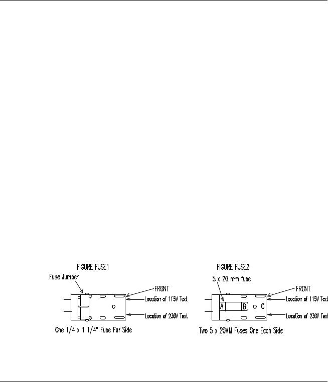
Fuse Configuration
The main fuse(s) on the Paxar 656 / 636 are located inside the AC power entry receptacle. The entry has a fuse drawer that holds the fuse(s) and selects the appropriate line voltage. If the number in the window DOES NOT match the AC line intended to be supplied to the printer, DO NOT plug the power cord in. Re configure as follows:
1)Using a flat blade screw driver, open the AC entry by lifting the tab just above the voltage indicator window.
2)Remove the red fuse drawer.
3)Remove all fuses and the fuse jumper if it is present.
4)Insert into the fuse drawer the correct number and style of fuses and fuse jumper for your application.
Configuration Number One: |
Line voltage between the range of |
|
90 - 132VAC @ 50 - 60Hz |
1)Install one 921167 - 10.0A 250V Fast Acting 1/4 x 1 1/4"
2)Install one Fuse Jumper
See Figure FUSE1
Configuration Number Two: Line voltage between the range of 180 - 265VAC @ 50 - 60Hz
1) Install two 921168 10.0A 250V Fast Acting 5 x 20MM
NOTE: The fuse jumper must be removed to install both 5 x 20mm fuses.
The fuses must be between points A and B as shown not B and C.
See Figure FUSE2
4)Reinsert the fuse drawer into the AC entry with the desired voltage up.
5)Close the AC entry and verify the correct voltage is now visible.
P.C. Board Installation
Install P.C. Boards as follows:
Users Manual Model 656/636 |
Printer Setup • 7 |

Memory Card Option Board (350016) |
- Slot 5 (from back) |
Diskless Rom Bd. (281164) |
- Slot 4 |
Thermal Control Bd. (351105) |
- Slot 2 |
Head Control Bd. (351106) |
- Slot 1 |
TCB Dip Switch S2 Settings
TCB DIP SWITCH S2 SETTINGS
1 |
DPI |
OFF = 240 |
ON = 300 |
2 |
DPI (Undefined) |
OFF = Default |
ON = |
3 |
MACHINE TYPE |
OFF = 656 |
ON = 636 |
4 |
MACHINE TYPE (Undefined) |
OFF = Default |
ON = |
5 |
JAM SENSOR |
OFF = not installed |
ON = installed |
6 |
UNDEFINED |
OFF = Default |
ON = |
7 |
UNDEFINED |
OFF = Default |
ON = |
8 |
UNDEFINED |
OFF = Default |
ON = |
Installing the Power Cord
A power cord is shipped with each printer. The cord for 110 volt printers, will use the standard three prong plug used in the U.S.A. A 220 volt printer and other 110 volt configurations must have the receptacle end of the connector removed and the proper plug installed. It is the customers responsibility to have the plug and alteration work done by a certified electrician. Paxar supplies printers to many countries with many variations. Therefore we leave this to the customer to make the proper selection for their country.
8 • Printer Setup |
Users Manual Model 656/636 |

Installing the PC Interface Cable
The 656 / 636 requires a 9-pin RS232 cable. This cable is provided with the printer. If the cable was not found it can be order from PAXAR (Part no. 351124).
The male end of the cable should be connected to the 9-pin D-shell female connector that is located on the right side of the printer. The female end of the cable is made to fit a 9-pin male RS232 connector on the back of the PC.
Installing the PC Software
The software to drive the Paxar family of printers is covered in separate documentation. The "Formatter" software to create formats by the customer for the Paxar 656 / 636 printer is a Windows application. The original software "Selfform" will not create formats for the 656 / 636. The new "Formatter" package is capable of making formats for all Paxar control printers.
The original DOS version of "PCMate" has been updated to drive the 656 / 636 printer. PCMate DOS version 3.05 or later needs to be used.
The printer is also capable of operating directly from a mainframe when using the RS232 interface and Paxar's PCL command language.
Users Manual Model 656/636 |
Printer Setup • 9 |
Product Description
Printer Description
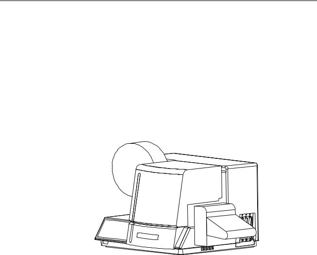
The PAXAR MODEL 656 / 636 THERMAL PRINTER (Figure 2) is an electronic printer that can print on Fabric Tapes, Card Stock, Heat Seal Stock and Pressure Sensitive roll stocks. This printer interfaces to a computer or a main frame system that allows the customer to print computer input or even design a label with PAXAR’S PCMate Plus's "FORMATTER" program. This printer can generate a complete label printed on one side.
•Design your own labels on a PC
•Computer interface = IBM Compatible
•Mainframe direct interface
•RS232 9 Pin D shell female Serial interface connector
Figure 2 PAXAR MODEL 656 / 636 LABEL PRINTER
10 • Product Description |
Users Manual Model 656/636 |

Personal Computer Specifications
This specification describes the hardware and application software requirements for the Personal Computer that is connected to the PAXAR 656 / 636 Printer.
The PAXAR 656 / 636 Printer uses a DOS Version of PCMate or a Windows version of “PcMate Plus / Formatter ”. These applications create the tag or label formats (layouts) then fill and transfer data to the printer through the serial port of the computer.
“PcMate Plus / Formatter ” Requires the following; - IBM® PC or compatible
- Microsoft Windows® 95 or higher (Including Win 2000, ME, and NT) - 16 Megabytes RAM (minimum) - 32 Megabytes recommended
- 50 Megabytes (minimum) free disk space
- Pentium or Pentium Type processor - 200 Mhz or higher - 3-1/2" floppy drive
Refer to your specific software package for proper installation procedures.
Unit Specification
Narrow web thermal transfer or thermal direct one sided printer |
|
method: |
Speed - up to 7 IPS (177.8mm/second) |
|
|
|
|
Label Size |
Max: up to 5.125" (130.2mm) web x up to 7" (177.8 mm) feed cut and stacked up to 14.0" |
|
(355.6mm) feed w/ rewind |
|
Min: 1" (25.4mm) web x 1" (25.4mm) feed |
|
|
Print Area |
Max: up to 5" (127mm) web x up to 13.875" (352.4 mm) feed |
|
Min: None |
|
|
Resolution |
240 DPI x 240 DPI standard domestic |
|
300 DPI x 300 DPI standard internationally |
Fonts |
Two scalable fonts resident: condensed, standard, and bold typefaces, upper and lower case |
|
4pt up to 96pt (300 DPI), 6pt up to 96pt (240 DPI) |
|
all rotations 0°, 90°, 180°, 270° |
Logos |
No restriction on number or size per tag (up to maximum image area) |
|
all rotations 0°, 90°, 180°, 270° |
Care |
Full International Set |
Symbols |
.200" (5.1mm) x .200" (5.1mm) (240 DPI) (4 care symbols per 1" (25.4mm)) |
|
.156" (3.9mm) x .187" (4.8mm) (300 DPI) (5 care symbols per 1" (25.4mm)) |
|
All rotations 0°, 90°, 180°, 270° |
Justification |
Left, Right, and Center field selectable |
Stock |
Support for blank or pre-printed fabrics, blank or pre-printed card stock and die cut blank or |
|
pre-printed pressure sensitive |
Interface |
PAXAR PCL via RS232 serial port - 9 pin D-shell |
|
Verifier serial port - 8 pin MicroDin |
Users Manual Model 656/636 |
Product Description • 11 |
Control |
Push-button printer function with 2 Line x 24 Character International LCD Backlit Display |
Panel |
|
Dimensions |
16.0" (406.4 mm) high x 27" (685.8 mm) wide |
|
including stacker x 18.5" (469.9mm) deep |
Weight |
57 Lbs. ( 26Kg.) |
|
|
Electrical |
90-132 / 180-265 VAC 50-60Hz 10Amp Switch selectable |
|
|
Temperature |
41°F (5°C) to 104°F (40°C) |
Humidity |
5% to 90% non-condensing |
Other |
- Downloading of information while machine is operating |
Features |
- Sequenced Fields |
|
- Time/Date Stamping |
|
- Life Counts |
|
- Operator adjustable: strobe, cut position, print position, baud rate, and buffer size |
|
- Error Detection of: stock out, ink out, print head open, guard open, full stacker, and print head |
|
over-temperature |
|
- Display: labels left to print in a batch, batch ID, total life inches, total life cuts |
|
- Self Diagnostics |
|
- Missed sense mark detection and correction |
|
- Slot, Notches, Hole or Reflective registration detection |
Ink Ribbon |
PAXAR standard thermal colors and widths |
Options |
- VL70 Barcode Verifier System |
|
- Rewind Unit (110V or 220V) |
|
- Reflective Sensor (Back of Web Only) |
|
- PCMate |
|
- SELFFORM |
|
- Spare Parts Kit |
|
- International Hardware Kit |
|
|
12 • Product Description |
Users Manual Model 656/636 |
Printer Operation
Installing Ink Ribbon
NOTE: WHEN THIS MACHINE IS TURNED ON FOR THE FIRST TIME,
A PAXAR FIELD ENGINEER MUST BE PRESENT.
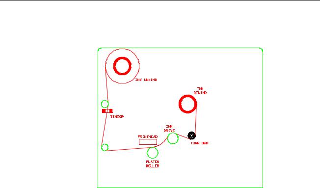
Figure 2
(Threading path)
The ink ribbon comes pre-packaged in a plastic bag. For best results, leave the ink ribbon wrapped in this bag until you are ready to use it in the printer. Use the procedure and diagram below for loading the ink.
1)Unwrap the ink ribbon and put it on the ink-ribbon supply arbor (Figure 2) by pressing it on to the arbor when the three slots are lined up.
2)Make sure the ink ribbon comes off the roll in the direction shown below and is threaded as illustrated (see Figure 2).
NOTE: A new ink ribbon has a leader which makes it easier to use when threading the ribbon through the print area.
3)Put an empty ink-ribbon take-up core on the ink-ribbon take-up arbor. The ink take-up core must be at least as wide as the ink supply. The tape on the supply roll of ink will be used to fasten the leader to the core.
4)Advance the ink until the leader starts to wrap around the take-up core.
5)Lower the take-up arbor into place. You will have to rotate the ink arbor as the swing arm is returned to the drive roller to keep excess slack ink from between the print head and the take up roller.
NOTE: Make sure that the ink-ribbon take-up core and the ink-ribbon supply roll are against the edge guide plate so that the ink ribbon tracks straight through the print station.
Users Manual Model 656/636 |
Printer Operation • 13 |
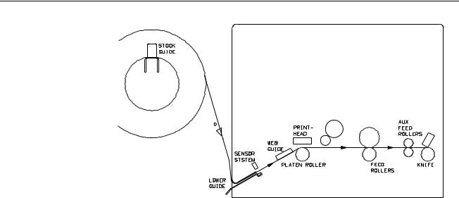
Loading Stock
Ink Take-up
Stock out
Decurler
FIGURE 3 STOCK THREADING
LOADING STOCK FOR THE FIRST TIME
1)Slide the outboard stock guide to a position wider than the roll of stock to be loaded. Set the stock roll core over the outboard guide and slide the roll to the back guide. Move the outboard stock guide in until it contacts the stock roll.
2)Remove the tape or pull the glued end of the stock loose from the supply roll of stock. Pull off about 2 feet (.5 m) of stock to thread it through the printer.
NOTE: If the material was glued to the core, cut off all material that has glue on any surface.
3)Open the print head by pressing the release lever.
4)Open the web guide just before the print head platen roller to a width wider than the stock to be used.
5)With the cover in the up position, slide the leading edge of the stock through the lower guide that also contains the sensor system. Keep the stock to the back of the printer as the unit is a back justified printer.
6)As the stock exits the sensor area, continue to slide the stock through the print station. At this point you may need to direct the edge of the stock below the ink drive roller.
7)With the feed roller open, slide the stock through the two feed rollers, aux. feed and through the knife into the stacker approximately 1/2 to 3/4 of an inch.
8)Check that the stock is still to the back of the printer.
9)Adjust the front web guide, just in back of the platen roller, until it just misses the front guide. This is to allow for the slight tolerance variation in the stock.
10)Close the feed roller and the print head station.
11)Rewind any loose stock onto the supply roll.
14 • Printer Operation |
Users Manual Model 656/636 |
Butt Splice
NOTE: DO NOT RUN BUTT SPLICES THROUGH THE PRINT STATION
The PAXAR 656 / 636 has been designed with the operators need to change supplies quickly in mind. Re threading the stock is quicker than butt splicing. If you have determined a butt splice is necessary, tape the free end of the new stock roll & the free end still in the printer together. Make sure you have determined how the new roll will go on the printer to prevent any twist in the stock.
Following the procedure previously outlined, load new supply roll onto the printer. Remove all slack by rotating the supply roll counterclockwise. Advance splice beyond the print station. This can best be accomplished by using the stock feed function switch combination (see push button description in Control Panel section).
NOTE: Whenever stock of a different type or width is put on the printer, a sample run should be performed. If the print quality is acceptable, you can immediately begin your production run. If the print quality needs to be optimized, refer to the Setup Procedures and perform the procedure needed to make the necessary improvement.
Web Guide Adjustment
The Paxar 656 / 636 printer has been designed with the operators needs in mind. Therefore there are only two web guides in the printer that may need to be changed as the width of the rolls change for formats. Neither of these adjustments require a tool. Guide adjustments have already been covered in the stock loading procedure.
The first guide is on the roll support bar. The front guide must be slid to the back of the printer to hold the supply roll against the back guide plate. Place your thumb against the round stub close to the support bar. Push the guide until it firmly contacts the front of the supply roll. This will hold the supply against the back guide. This completes the adjustment for this guide.
The second guide is located just to the left of the print head and platen roller. This guide must be set close to the front edge of the card stock but must not pinch the edges. If the guide is too tight, the card stock will have rolled up edges. To move this guide place your finger to the inside or the guide opposite the guide pressure screw and pull to widen the opening. To close down the opening, place your thumb against the side of the pressure screw to slid the guide in.
NOTE: THE BACK EDGE OF THE WEB GUIDES HAVE BEEN FACTORY SET. CHECK THAT THE FORMAT HAS BEEN MADE CORRECTLY BEFORE MAKING FURTHER ADJUSTMENTS.
There are two independent adjustments and one fixed back guide. The one fixed back guide is opposite the platen roller guide. This has been located to control the edge of the stock to the first dot on the print head. This location is critical to Paxar's Formatter software. Do not adjust this guide with out consulting a Paxar service engineer.
The adjustable back guide is located on the back of the stock support bar. This guide is moved by loosening the button head screw located to left of the support bar. Loosen the screw and slide the forward or back as needed. The ideal location is to measure from the front of the plate 31/32" (24.6mm) back to the housing.
Users Manual Model 656/636 |
Printer Operation • 15 |

The only other adjustment for the back of the web is the back stacker up-right rail. To move the location of the up-right loosen the knob under the stacker and slide the unit in or out as needed. The up-right rail should be located approx. 1/16" (1.5mm) to the back of the label or tag as it enters the stacker.
Print Head Open / Close
The print head module is to be opened and closed for threading the stock and ink. The unit must also be opened to clean the head and for print head replacement. Later in the manual, under separate heading, cleaning and replacement will be covered.
The print head has an interlock switch that prevents the printer from running with the head in the open position. If the head is open the display will read GUARD OPEN. Both the top cover and head use the same command.
WARNING: DO NOT TOUCH THE PRINT HEAD WITHOUT WEARING THE ANTI-STATIC GLOVES AND THE STATIC WRIST STRAP.
To open the print head for threading supplies, press the lower portion of the latch (see figure ). The head mount plate will hinge from the back to swing open.
Figure Print Head Open / Closed
To close the head mount plate, move the head down while depressing the latch.
When the mount plate swings past the top of the latch release
16 • Printer Operation |
Users Manual Model 656/636 |
Control Panel Operation
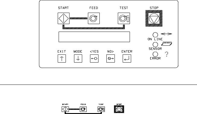
Printer Controls
Start
-Starts the printer
-ON LINE light must be GREEN (Batches downloaded to be printed)
Feed
-FEED and START must both be used
-Feed will stop when the buttons are released
-Labels between the head and knife will be cut and stacked as finished labels
-Stock moves through in one continuos strip
-Stock moves through without printing
-Ink will not advance, ink save on the 656 / 636 will automatically be activated.
-The print head must latched in the down position.
Test
- TEST and START must both be used
Users Manual Model 656/636 |
Control Panel Operation • 17 |
-Test will stop when the buttons are released
-Labels between the head and knife will be cut and stacked as finished labels
-Stock moves through in one continuos strip
-Stock moves through with test pattern printing
-The ink will advance with the stock.
-The print head must be latched in the down position.
Stop
-The stop button will stop the printer at the end of the current label being printed.
18 • Control Panel Operation |
Users Manual Model 656/636 |

Indicator Lights
The Paxar 656 / 636 has three Indicator lights. These lights are used along with the
LCD display to tell the operator the current status of the printer.
On Line
OFF
-Has not been powered on.
-Is in it's power - up sequence.
-Failed the system test
After Power Up Sequence:
-Printer is running.
ORANGE
-System is operational
-Ready for batches to be downloaded
GREEN
-batches to print, ready to start
Sensor
GREEN = "C" SENSOR
-Printer is stopped, - light is on, - sensor is setting over a web sensor mark
-Flashing light while the printer is running, - the sensor is in-line with the registration HOLES
ORANGE = REFLECTIVE SENSOR
- Flashing light while the printer is running, - the sensor is in-line with the registration PRINTED MARKS
Error
ORANGE
- System inter-lock triggered, display for error.
Users Manual Model 656/636 |
Control Panel Operation • 19 |

Front Panel Menu Functions
Ready For Batches |
Î |
Print Reports |
Î |
|
|
|
|
|
|
Ð |
|
|
|
|
|
|
|
Last Verifier Scan |
|
|
|
|
|
|
|
Ð |
|
|
|
|
|
|
|
Verifier History |
|
|
|
|
|
|
|
Ð |
|
|
|
|
|
|
|
Verifier Setup |
|
|
|
|
|
|
|
Ð |
|
|
|
|
|
|
|
Clear Verifier Scan |
|
|
|
Memory |
|
|
|
|
|
Setup |
Î |
Life Counts |
Î |
Protected Features |
|
|
|||
|
|
|
|
|
Ð |
|
Ð |
|
Ð |
|
|
|
|
|
Print Position |
|
Label Counter |
|
Set Date / Time |
|
|
|
|
|
Ð |
|
Ð |
|
Ð |
|
|
|
|
|
Cut Position |
|
Total Labels |
|
Change Password |
|
|
|
|
|
Ð |
|
Ð |
|
Ð |
|
|
|
|
|
Cutter Enable / |
|
Total Inches |
|
Change Language |
Disable |
|
|
|
|
|
|
|
|
|
Ð |
|
|
|
Ð |
|
|
|
|
|
Adjust Strobe |
|
|
|
Verifier Enable / |
|
|
|
|
Disable |
Ð |
|
|
|
|
|
|
|
|
|
Change Emulation |
|
|
|
|
|
|
|
|
|
Mode |
|
|
|
|
Ð |
|
|
|
|
|
|
|
|
|
Change Ink |
|
|
|
|
|
|
|
|
|
Transfer Type |
|
|
|
|
Ð |
|
|
|
|
|
|
|
|
|
Checkout Format |
|
|
|
|
|
|
|
|
|
|
|
|
|
|
20 • Control Panel Operation |
Users Manual Model 656/636 |
LCD Display
The LCD display is a 2 line, 24 character, with back lighting feature for easy readability. The first line of the display in most cases will be a prompt or question. the second line is the response.
Diagnostic Tests
During power up the following tests and screens will be displayed.
ENGLISH ONLY VXX.XX
DIAGNOSTIC TEST 1
This screen is displayed during the Control Panel test.
This screen will be displayed while the Front Panel is initializing and waiting for the TCB response. The top line will display the FRONT PANEL code version and the machine language (ENGLISH,GERMAN,SPANISH ETC). For example if German were the second language installed the screen would look as follows:
GERMAN / ENGLISH VXX.XX
DIAGNOSTIC TEST 1
The code will check the functionality of the LED's and the display. Each state of the LED's will be checked - (red, green, amber and off). The code will check the LCD display by writing a character to the display, checking for communications and then reading the character back and comparing with the code. If an error occurs, the code will halt the diagnostic test and blink the ERROR LED.
The keypad is also checked during DIAGNOSTIC TEST 1. Each key is tested to see if it is stuck on. If a fault condition is detected, the test is halted and the screen will display the first error key found with the following display:
(BUTTON NAME) KEY STUCK DIAGNOSTIC TEST 1
The (BUTTON NAME) will be one of the push button names on the front panel - START, FEED, TEST, STOP, EXIT, MODE, <YES, NO>, OR ENTER.
When the code has finished the above tests, the code will attempt to communicate with the Control Board (TCB). If all tests are complete and no errors detected, then the system will go to DIAGNOSTIC TEST 2 and display the TCB code version.
CONTROLLER VXX . XX
DIAGNOSTIC TEST 2
This screen should be displayed once the TCB has requested signon from the Front
Panel and the system is waiting for the AT to complete its initialization.
Users Manual Model 656/636 |
Control Panel Operation • 21 |

HOME SCREEN
READY FOR BATCHES
IMAGER VXX . XX
|
OR |
|
|
BATCH ID |
QTY |
PCL001 |
000000010 |
When the printer is powered up and all initializations are complete, and if there are no Batches to print, the HOME screen will be “READY FOR BATCHES" and the A.T. code version number (IMAGER VXX.XX) will be displayed.
When at the "READY FOR BATCHES" screen, and the HOST is mapping, the screen will display :
BUILDING IMAGE
IMAGER VXX . XX
When at the "READY FOR BATCHES" screen and there are no batches and the "ENTER" key is held down the screen will display the last batch printed (if any).
LAST BATCH WAS XXXXXXX
IMAGER VXX . XX
When there are Batches to be printed the HOME screen will be "BATCH ID QTY" screen, the Batch ID / Batch Qty screen will display the currently cutting batch ID and labels left to cut.
If the printer is performing a FEED or a TEST pattern this screen will show "FEEDING" or "PRINTING TEST PATTERN" respectively on line two.
PAXAR 656/240
IMAGER VXX . XX
This is the MACHINE ID screen. This screen shows the machine model - (656 or 636) and the print head type - (240DPI or 300 DPI). This screen will momentarily appear whenever the EXIT / Up arrow is pressed, and there are batches to be printed.
After this momentary display, the "HOME" screen is again displayed. Pressing the MODE / Down Arrow key will take the user to the next screen.
Pressing the EXIT / Up Arrow key will take the user back to the HOME screen.
22 • Control Panel Operation |
Users Manual Model 656/636 |
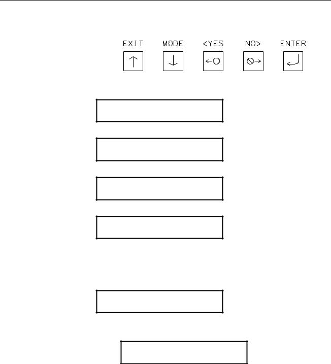
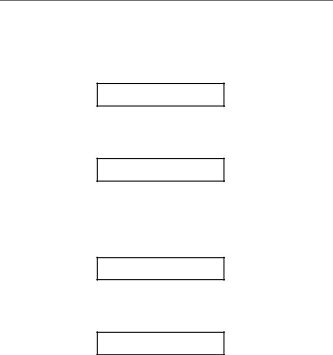
Display Modes
There are four (4) main mode levels which are selected and modified using the following function keys:
Use the MODE ↓ key to move through the main mode screens shown below:
PRESS ENTER FOR
PRINT REPORTS
PRESS ENTER FOR
SETUP
PRESS ENTER FOR
LIFE COUNTS
PRESS ENTER FOR
PROTECTED FEATURES
Use the EXIT ↑ to move to the HOME screens.
Print Report Mode
Use the Mode ↓ key to move to the following screen.
PRESS ENTER FOR
PRINT REPORTS
Use the Enter key to enter this mode.
PRESS ENTER TO
PRINT LAST VERIFIER SCAN
This is the first screen under Reporting features. This screen will appear if a verifier is connected to the printer. This screen allows the user to print the last scan report.
Prints the failure cause for the last bad barcode scan.
Users Manual Model 656/636 |
Control Panel Operation • 23 |
PRESS ENTER TO
PRINT VERIFIER HISTORY
This screen follows the PRINT LAST VERIFIER SCAN screen if a verifier is connected to the printer. This screen allows the user to print history report of the scanner reads.
Prints a report of the history of barcode scan quality.
PRESS ENTER TO
PRINT VERIFIER SETUP
This screen follows the PRINT VERIFIER HISTORY REPORT screen if a verifier is connected to the printer. This screen allows the user to print a verifier report containing verifier setup information.
Prints a report of all verifier current settings.
ENTER TO CLEAR
VERIFIER SCAN MEMORY
This screen follows the BARCODE VERIFIER ON screen if there is a verifier connected to the printer. This screen allows the user to clear the scan history memory in the verifier.
Pressing ENTER clears the verifier scan history.
Pressing the MODE ↓ key will take the user to the Strobe adjust screen. Pressing the EXIT ↑ key will take the user back to the HOME screen.
Setup Mode
Use the Mode ↓ key to move to the following screen.
PRESS ENTER FOR
SETUP
Use the Enter key to enter this mode.
CHANGE PRINT
PRINT: 0 NEW PRINT: + 2
For 300 and 240 dpi machines = .016" increments.
Use the <YES key to decrease the number and the > NO key to increase the number.
Adjustment from - 9 to + 10. Zero is the middle of the range Use the Enter key to save the new value
24 • Control Panel Operation |
Users Manual Model 656/636 |
 Loading...