


Patriot PT-R24, PT-R36, PT-R36-24M-2B, PT-R60, PT-R60-24MG Operating Manual
...
IMPORTANT FOR YOUR SAFETY
THIS MANUAL HAS BEEN PREPARED FOR PERSONNEL QUALIFIED TO INSTALL GAS EQUIPMENT, WHO SHOULD PERFORM THE INITIAL FIELD START-UP AND ADJUSTMENTS OF THE EQUIPMENT COVERED BY THIS MANUAL.
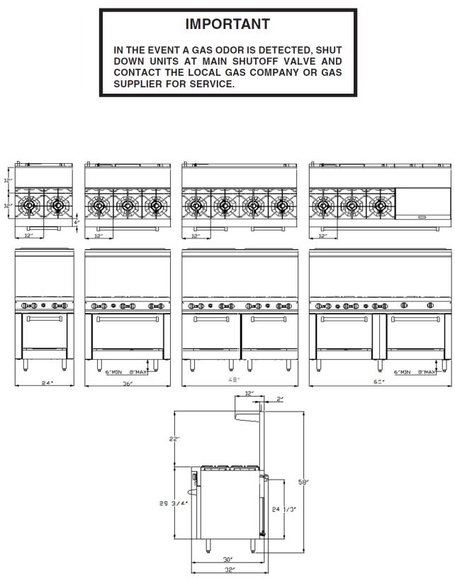
POST IN A PROMINENT LOCATION THE INSTRUCTIONS TO BE FOLLOWED IN THE EVENT THE SMELL OF GAS IS DETECTED. THIS INFORMATION CAN BE OBTAINED FROM THE LOCAL GAS SUPPLIER.
Dimension of Overall
24” Range |
36” Range |
48”Range |
60”Range |
2


Installation, Operation and Care:
PLEASE KEEP THIS MANUAL FOR FUTURE REFERENCE
GENERAL
Ranges are produced with quality workmanship and material. Proper installation, usage and maintenance of your range will result in many years of satisfactory performance.
Suggests that you thoroughly read this entire manual and carefully follow all of the instructions provided.
THIS APPLIANCE IS EQUIPPED FOR NATURAL GAS,
for conversion to LP gas please see gas conversion instruction manual attached. Orifices necessary for LP (propane) (natural) conversion are provided. Please refer to page 3 the orifice size list when you do gas conversion
INSTALLATION
UNCRATING
This range was inspected before leaving the factory. The transportation company assumes full responsibility for safe delivery upon acceptance of the shipment. Immediately after unpacking, check for possible shipping damage. If the range is found to be damaged, save the packaging material and contact the carrier within 15 days of delivery.
Uncrate unit carefully and place in a work-accessible area as near to its final installed position as possible. Remove all shipping wire and wood blocking.
Before installing, check the type of gas supply (natural or propane) to make sure they agree with the specifications on the rating plate located on the inside of the lower kick panel. If the supply and equipment requirements do not agree, do not proceed with the installation. Contact your dealer or company immediately.
LOCATION
The appliance must be installed under a ventilation hood.
The equipment area must be kept free and clear of combustible substances.
The range, when installed, must have a minimum clearance from combustible construction of 12" (304 mm) at the sides and 10" (253 mm) at the rear. Clearance from non-combustible construction is 0" at the sides and 6" (152 mm) at the rear.
The installation location must allow adequate clearances for servicing and proper operation. A minimum front clearance of 40" (1016 mm) is required.
The range must be installed so that the flow of combustion and ventilation air will not be obstructed. Adequate clearance for air openings into the combustion chamber must be provided. Make sure there is an adequate supply of air in the room to allow for combustion of the gas at the burners.
4
INSTALLATION CODES AND STANDARDS
Ranges must be installed in accordance with:
In the United States of America:
1.State and local codes.
2.National Fuel Gas Code, ANSI/Z223.1 (latest edition). Copies may be obtained from The American Gas Association, Inc., 1515
Wilson Blvd., Arlington, VA22209.
In Canada:
1.Local codes.
2.CSA B149.1 Natural Gas and Propane Installation Code.
3.CSA C22.1 Canadian Electric Code.
4.CSA C22.2 Canadian Electric Code.
The above are available from the Canadian Standard Association, 5060 Spectrum Way, Suite 100, Mississauga, Ontario, Canada L4W 5N6.
ASSEMBLY: Ranges Mounted on Casters
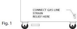
Ranges mounted on casters must use a flexible connector (not supplied by CHEF N’SAVE) that complies with the Standard for Connectors for Movable Gas Appliances, ANSI-Z21.69 • CSA 6.16 and a quick-disconnect device that complies with the Standard for Quick-Disconnect Devices for Use With Gas Fuel, ANSI-Z21.41 • CSA 6.9. In addition, adequate means must be provided to limit movement of the appliance without depending on the connector and the quick-disconnect device or its associated piping to limit appliance movement. Attach the restraining device at the rear of the range as shown in Fig. 1. Remove two screws from the rear of the range and install the tie-down strap shipped with the casters using these screws (Fig. 1). Attach the gas line strain relief to the tie-down strap at the rear of the range (Fig. 1).
If disconnection of the restraint is necessary, turn off the gas supply before disconnection. Reconnect this restraint prior to turning the gas supply on and returning the range to its installation position.
Separate instructions for installing casters to the range are included with the casters. Note: If the range is installed on casters and is moved for any reason, it is recommended that the range be leveled front to back and side to side.
5
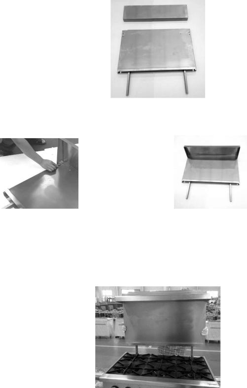
Backsplash
The standard Restaurant Range is equipped with a 23" (584 mm) high backsplash and shelf.
1.Remove the backsplash components from the crating materials.
2.Assemble the required components as shown in Fig’s. 2 and 3 and 4.
Fig. 2
3. Tighten the four screws to secure the shelf.
Fig. 3 |
Fig. 4 |
|
4 Lift the assembly up, sliding the channels into the space provided at the rear of the range.(Fig’s. 5).
Fig. 5
6
 Loading...