

Page 1

ISO 9002
C E R T I F I E D
UL FILE A1130 PARTLOW CORPORATION
Form 2963 • Price $7.50
Edition 8 • © October 1993
Updated March 1996
ARC 4100
Installation, W iring, Operation Manual
The Partlow Corporation • Two Campion Rd. • New Hartford, NY 13413 USA • 315-797-2222 • FAX 315-797-0403
Page 2

PAGE 2
nformation in this installation, wiring, and operation
manual is subject to change without notice. One
I
manual is providedwith each instrument at the time of
shipment. Extra copies are available at the price
published on the front cover.
Copyright © October 1993, The Partlow Corporation, all
rights reserved. No part of this publication may be
reproduced, transmitted, transcribed or stored in a
retrieval system, or translated into any language in any
form by any means without the written permission of the
Partlow Corporation.
This the the Eighth Edition of the ARC 4100 Recording
Controller Manual. It was written and produced entirely on
a desk-top-publishing system. Disk versions are
available by written request to the Partlow Advertising and
Publications Department.
NOTE
We are glad you decided to open this manual. It is
written so that you can take full advantage of the features of
your new ARC 4100 analog chart recording controller
It is strongly recommended that Partlow equipped
applications incorporate a high or low limit protective device which will
shut down the equipment at a preset process condition in order to preclude possible damage to property or products.
.
Page 3

Table of Contents
SECTION 1 - GENERAL Page Number
1.1 Product Description 5
SECTION 2 - INSTALLATION & WIRING
2.1 Installation and wiring 8
2.2 Unpacking 8
2.3 Location 8
2.4 Mounting 8
2.5 Preparation for Wiring 10
2.6 Wiring Connections 10
SECTION 3 TUNING & ALARM ADJUSTMENTS
3.1 Tuning and Alarm Adjustments 18
3.2 Alarm Adjustments 19
PAGE 3
SECTION 4 - SERVICE
4.1 Service 22
4.2 Calibration 23
4.3 Field Range Change 28
APPENDICES
A - Board Layouts and Jumper Positioning
A-1 - Recorder Board 30
A-2 - Controller Board 31
B - Order Matrix 33
C - Specifications 35
Warranty Inside back page
Page 4

PAGE 4
FIGURES & TABLES
Figure 1-1 Front Panel Display & Thumbwheel Station 6
Figure 1-2 Recording Controller Display & Thumbwheel Adjustment 7
Figure 2-1 Installation View & Dimensions 9
Figure 2-2 115 and 230 Wiring Hookup 11
Figure 2-3A Installaion for 115VAC Signal Wiring To Rectifier 12
Figure 2-3 Input Power & Signal Connections Layout 12
Figure 2-4 Thermocouple Process Input 13
Figure 2-5 RTD Process Input 13
Figure 2-6 Volt, Millivolt & Milliamp Process Input 14
Figure 2-6A Milliamp Process Input with Power Supply 14
Figure 2-7 Remote Output Input 15
Figure 2-8 Relay Output Connections 15
Figure 2-9 SSR Driver Output Connections 16
Figure 2-10 Current Output Connections 17
Figure 3-1 Process Alarm Actuation 20
Figure 3-2 Deviation Alarm Actuation 20
Figure 3-3 Deviation Band Alarm Actuation 21
Figure 4-1 Changing Pens 22
Figure 4-2 Recorder PWA Layout for Calibration 27
Figure 4-3 Controller PWA Layout for Calibration 27
Figure 4-4 Range Change Procedure 28
Table 4-1 Troubleshooting Guide 28
Page 5

Product Description 1.1
1.1.1 GENERAL
The unit is a circular chart recording instrument capable of measuring, recording, and
controlling up to two process variables from a variety of inputs. Applications include
temperature (degrees F and C), pressure, relative humidity, pH level, electrical measurement,
flow and others.
Instrument capabilities such as recording, controlling functions, alarm settings, and other
parameters are selected from the order matrix and are factory implemented.
The process input for each pen is configured, at the factory, per order matrix model selection
and directly connects to either thermocouple, RTD, mVDC, VDC, or mADC inputs. Most
changes to input type are easily accomplished in the field. However, an input change from
thermocouple to RTD on units with Recorder PWA's at revisions before Rev D should be done
only after consulting with factory. Inputs are factory calibrated and will require re-calibration if
changed in any way. Thermocouple cold junction compensation is performed automatically by
the instrument.
The instrument can operate with either 115VAC or 230VAC line voltage at 50 or 60Hz. The
voltage and frequency are selected when ordering. The 230VAC line voltage option includes
soldered jumpers to allow the electronics to be configured to 115VAC line voltage when
necessary. The chart drive is not switchable, and must be changed whenever the line
voltage or frequency is changed.
PAGE 5
The instrument is housed in a durable enclosure suitable for panel or surface mounting.
1.1.2 RECORDING
The unit incorporates a 10 inch circular chart. One box of standard charts is provided with
each instrument. Charts are available in a wide selection of zero based, non-zero based,
reverse, and dual scale ranges. The instrument can be provided with one or two pens. Pen
1 is red and Pen 2 is green. Pens are of the disposable fiber-tip type. Changes in pens, as
well as charts, are quickly and easily accomplished.
Displays & Status Indicators
Setpoint is selected/observed using a 3 or 4 - digit pushbutton thumbwheel potentiometer.
Two LED indicators are provided :
INDICATOR COLOR DESCRIPTION
OUT1 Red Output 1 status
OUT2 Yellow Output 2 status
Page 6
PAGE 6
1.1.3 SETPOINT/STATUS INDICATORS
Each recording controller is provided with either a remote or local setpoint capability. If a
local setpoint is desired, the following selections are available:
• Three digit positive only thumbwheel
• Three digit positive and negative thumbwheel
• Four digit positive only thumbwheel
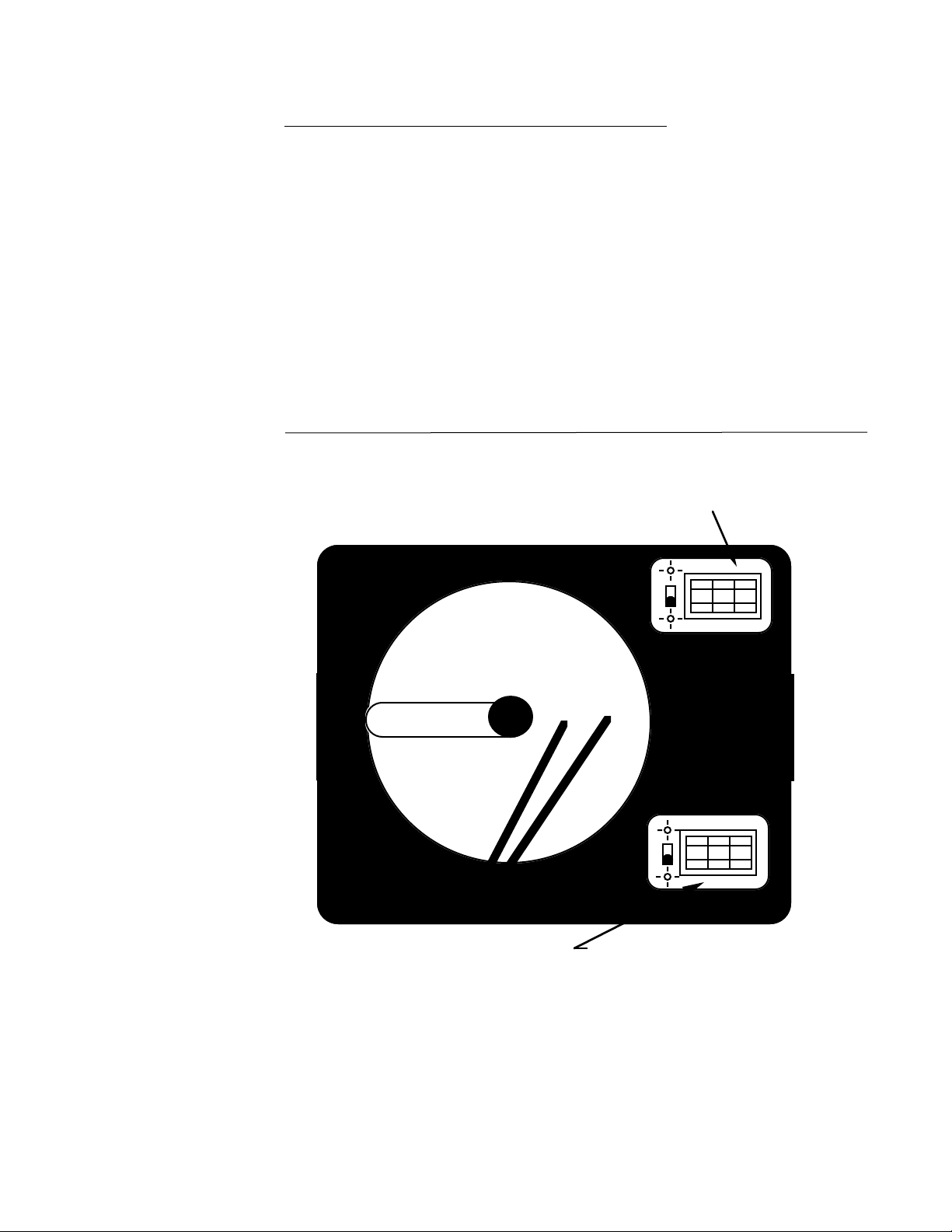
The thumbwheel provided in the upper right corner is for Pen 1 and the thumbwheel provided
in the lower right corner is for Pen 2. The status indicators provided depend upon the specific
pen function, e.g. alarm only, high limit, on-off controller relay, on-off controller SSR driver,
time proportioning relay, time proportioning SSR driver or 4 to 20mA. A detail of the status
indicators is shown in Figure 1-2. Status indication is provided for Pen 1 Output 1, Pen 1
Output 2, Pen 2 Output 1, Pen 2 Output 2.
Pen 1 and Pen 2 Output status indicators are Red LED's.
Pen 1 and Pen 2 Second output orAlarm indicators are Yellow LED's.
FIGURE 1-1
Front Panel Display
& Thumbwheel Station
PEN 1 THUMBWHEEL
& DISPLAY
---
000
+++
---
000
+++
PEN 2 THUMBWHEEL
& DISPLAY
Page 7
1.1.4 CONTROL
(
)
The Recording Controller is available with single and dual pen capability. Each pen is
specified independently and can be provided with one of several control outputs as well as a
second output for control or alarm conditions.
The instruments can be ordered as either high limit, on-off, time proportioning, or current
proportioning. Proportioning units include full PID (Proportional, Integral, and Derivative)
capability.
Remote setpoint capability can be provided for either Pen 1 or Pen 2 setpoint in lieu of local
setpoint. The remote setpoint may be either 4 to 20mA, 1 to 5 volts or a potentiometer.
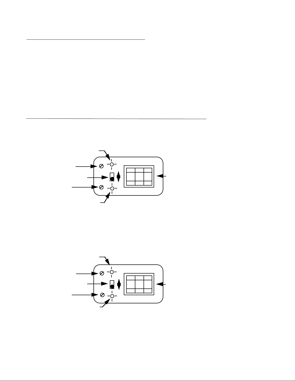
FIGURE 1-2
Recording Controller
Display and Thumbwheel
Adjustment
PAGE 7
Pen 1 Output 1
(Red)
Manual Reset
Adjustment
Output 2 or Alarm
Adjustment
Manual Reset
Adjustment
Output 2 or Alarm
Adjustment
Polarity
Switch
Pen 1 Output 2
Amber
Pen 2 Output 1
(Red)
Polarity
Switch
Pen 2 Output 2
(Amber)
PEN 1
-
+
PEN 2
-
+
+ ++
000
---
+++
000
---
PEN 1
THUMBWHEEL
PEN 2
THUMBWHEEL
Page 8

PAGE 8
Installation & Wiring 2.1
At shipment from the factory the instrument has been configured to accept input(s) as
specified. AC power input is as specified in the model number; 115VAC or 230VAC. Verify
the AC power input provided with the instrument prior to proceeding with installation.
Read these instructions carefully before proceeding with installation and operation. Electrical
code requirements and safety standards should be observed. Installation should be performed by qualified personnel.
Installation of the Instrument includes:
* Unpacking
* Location
* Mounting
* Preparation for Wiring
* Wiring Connections
Unpacking 2.2
Remove the instrument from the carton and inspect it for any damage due to shipment. If any
damage is noticed due to transit, report and file a claim with the carrier. Write the model
number and serial number of the instrument on the front cover of this Operation Manual for
future reference when corresponding with the factory.
Location 2.3
Locate the instrument away from excessive moisture, oil, dust, and vibration. Do not subject
the instrument to operating temperatures outside of 0 to 55° C. (0 to 131°F)
Mounting 2.4
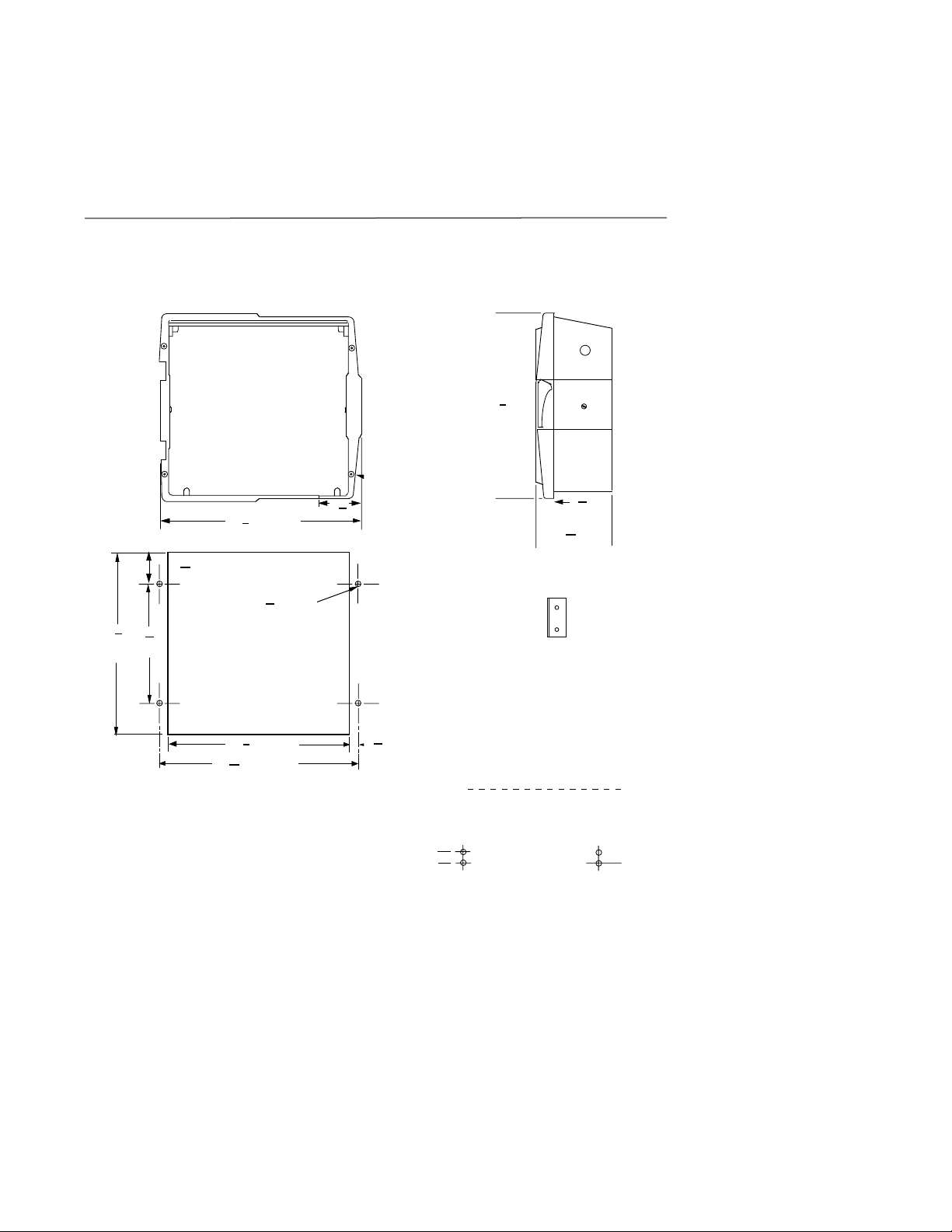
Figure 2-1 shows installation view and physical dimensions for the panel mounted instrument.
The panel that the instrument will be mounted in must provide rigid support for the approxi-
mately 20 pound Instrument. Adjacent Recorders or Recording Controllers may be mounted
within a minimum of 2 inches horizontally and 3 inches vertically, providing that proper panel
support is supplied.
PANEL MOUNTING HARDWARE REQUIRED: ( Not provided with instrument)
(4) 9/32" x 2" bolts w/nuts
(4) appropriate lockwashers
The location of the instrument is important and should be located in an area void of excessive
moisture, vibration, oil, and dust. The instrument should also be located in an ambient
temperature of 0 to 55° C (32 to 131° F).
For panel mounting, cut the panel hole to the dimensions shown in Figure 2-1 (page 9). If the
rear of the panel is accessible for wiring after installation, mount the instrument in the panel by
opening the hinged cover and fastening the instrument to the panel through the mounting
holes located in the case flange. If the rear of the panel is not accessible, the instrument must
be wired first. In this case, see wiring instructions.
Page 9
For surface mounting, install the brackets ordered separately to the sides of the instrument
case and mount to the surface.
FIGURE 2-1
EC1
16
1
2
1
(384.2 mm)
15
8
WIDTH OF COVER
19
2
(65.9 mm)
32
2
4
16
PAGE 9
5
12
1
7
8
(320.7 mm) (190.5 mm)
2
9
DIA.(7.1mm)
32
1
(342.5 mm)
13
2
15
( 354 mm)
13
16
Panel cut-out for flush mounting
2.5"
63.5mm
Page 10

PAGE 10
Preparation for Wiring 2.5
This section is divided into two parts: Wiring Guidelines, and Sensor Placement. Please
review this completely before proceeding with wiring of instrument.
The wiring guidelines contained in the following paragraphs must be followed to
ensure the best possible performance of the instrument. Please review this section
carefully before proceeding.
2.5.1 WIRING GUIDELINES
2.5.1.1 AC POWER WIRING
Clean AC power is required to ensure a proper installation. To be classified "clean" the
following must be met:
Earth Ground
Earth ground must be attached to the instrument's chassis. To verify that it is earth ground
being attached, make a resistance check from instrument chassis to the nearest metal water
pipe or proven earth ground. This reading should not exceed 1000 ohms.
2.5.1.2 WIRE ISOLATION
3 conduit openings, EC1, EC2, and EC3 are provided so wiring can be divided into separated
catagories.
* Analog input or output (i.e. thermocouple, RTD, VDC, mVDC or mADC)
* SPDT Relay or SSR driver outputs
* AC power
The only wires that should be run together are those of the same category. Each of these
must be isolated from each other .
2.5.2 SENSOR PLACEMENT (Thermocouple or RTD)
Thermocouple lead resistance should not exceed 300 ohms.
If this is exceeded, instrument accuracy could be affected.
Two wire RTD's should be used only for lead lengths less than 10 feet.
If the temperature probe is to be subjected to corrosive or abrasive conditions, it should be
protected by the appropriate thermowell. The probe should be positioned to reflect true
process temperature:
In liquid media - the most agitated area.
In air - the best circulated area.
Wiring Connections 2.6
All wiring connections are typically made to the instrument with it installed. Terminal connections should be made via terminal blocks with captive wire clamps, two 12 gauge wires
maximum.
Use the wiring connections, Figure 2-3 (page 12), for planning all wiring installation. The
layout in Figure 2-3 shows the general location and orientation of all terminal blocks. Terminal blocks are designated TB1 thru TB6. Figure 2-3 shows details for the various possible
input connections. Paragraph 2.6.2 provides descriptive detail for AC power connections.
Paragraph 2.6.3 details all input connections, and paragraph 2.6.4 provides wiring connection
details for all outputs.
Page 11

2.6.1 ELECTRICAL CONDUIT OPENINGS
Figure 2-1 shows the location of all electrical conduit openings that are provided on the
instruments. These openings are labeled EC1 thru EC3. It is recommended that wiring enter
the instrument through the conduit openings provided as follows:
EC1 - AC power
EC2 - Analog input and mAdc outputs
EC3 - SPDT relay or SSR driver outputs
Following these recommendations will help ensure proper operation .
Unused conduit openings should be sealed if exposed to the environment.
2.6.2 AC POWER WIRING CONNECTIONS
Avoid electrical shock. AC power wiring must not be connected at the source
distribution panel until all wiring connection procedures are completed.
Consult the model code and the wiring label for the appropriate line voltage for the unit.
Instruments specified with 230VAC power input, as specified in model number, are
provided with a soldered jumper which allows configuration back to 115VAC. Verify
soldered jumper configuration before proceeding with AC power wiring (see Fig.
4-4). Also ensure correct AC chart drive motor is installed (line voltage is stamped
on motor.
PAGE 11
CONNECT AC WIRING AS FOLLOWS:
1. Run AC power cable through the EC1 conduit opening as shown in Figure 2-1 (page 9).
2. Connect AC hot and neutral to terminals 1 and 2 respectively of TB1 as shown in
Figure 2-2 (below).
3. Connect Earth Ground to the instrument ground screw as shown in Figure 2-3 (page 12).
4. If Event Pen option is present, connect the 115VAC power through the EC1 conduit
opening as shown in Figure 2-1 (page 9) and as labeled in Figure 2-3A (page 12).
regardless of which line voltage supply used for instrument supply, event pen
operating voltage is 115 VAC only.
The event pen marks the circular chart on the outside edge of the paper. The pen
movement is short but a distinct difference can be seen between the On and Off cycles of
the pen. Typical event pen usage is for indication of an alarm condition.
Note:
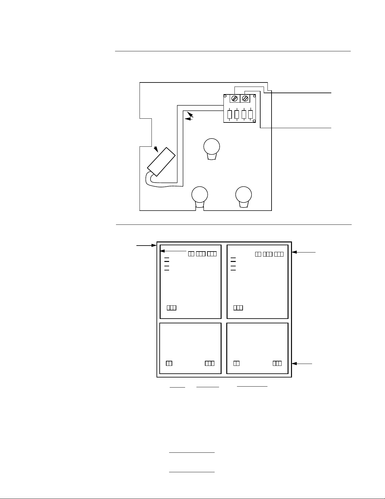
FIGURE 2-2
Neutral
Line 1
115 Hookup
Line 1
Line 2
230 Hookup
12
TB1
Note: Customer supplied disconnect and fuse (3 amps)
12
TB1
Page 12
PAGE 12
g
g
g
FIGURE 2-3A
Installation Instructions for 115VAC Actuating Signal Wiring
to Rectifier/100VDC Event Pen
Event Pen
Coil 100VDC
Wire Assembly
Platen Back
Rectifier
PWA
To EC1
115VAC
actuating
signal
(field supplied)
To EC1
Notes:
1. Signal Wire
to be stranded
14 or 16 Ga. Wire
2. Terminals will
accept 14 or 16
Ga. Wire
FIGURE 2-3
EC1
NEC Class 1
Wirin
GROUND
TB4
123 123
TB6
12 12123 123
BLOCK
Recorder PWA - Pen 1
J7, J6 - AC Power to chart drive motor
J5, J4 - AC Ground for chassis and chart drive
Recorder PWA - Pen 2
J7, J6 - AC Line Voltage (not used)
J5, J4 - AC Ground
12
123 123 123
J7
J6
J5
J4
RECORDER PWA
PEN 1 - RED
CONTROLLER PWA CONTROLLER PWA
TB1
TB2
TB3
TB4
TB5
TB6
TB3
TB2TB1
TB5
TERMINAL
1 & 2
1,2,3
1,2,3
1,2,3
1,2,3
1 & 2
J7
J6
J5
J4
RECORDER PWA
PEN 2 - GREEN
TB4
TB6
DESCRIPTION
AC Hot/Neutral
2nd Output Relay
N.O./Common/N.C.
1st Output Relay
N.O./Common/N.C.
Input Signal
+/- / RTD Common
Remote Setpoint]
+V Out / +/4 to20mA Output
+/-
123
12
TB5
TB3TB2TB1
EC3
NEC Class 1
Wirin
EC2
NEC Class 2
Wirin
Page 13

2.6.3 INPUT CONNECTIONS
Wiring connection for instrument inputs are by input type as described in the following
paragraphs. Each instrument is factory shipped ready to accept input(s) specified.
WARNING
Process input type for each pen can be changed. For Rev. D printed circuit boards and above
refer to Appendix A for jumper selection. For printed circuit boards below Rev D. consult the
factory before making changes to input types.
FIGURE 2-4
TB4
+
-
123
GROUNDED OR
UNGROUNDED
THERMOCOUPLES
MAY BE USED.
PAGE 13
2.6.3.1 THERMOCOUPLE PROCESS INPUT
Make thermocouple connections as shown in Figure 2-4. Use TB4 of the respective recorder
board for Pen 1 or Pen 2. Connect the positive leg of the thermocouple to terminal 1, and the
negative to terminal 2. For industrial environments with comparitively high electrical noise
levels, shielded thermocouples and extension wire is recommended. The shield thermocouple should be grounded at one, preferably at the source end.
FIGURE 2-5
TB4
+
-
1 23
TB4
+123
JUMPER
(Customer supplied)
3 WIRE RTD
2 WIRE RTD
2.6.3.2 RTD PROCESS INPUT
Make RTD connections as shown in Figure 2-5. Use TB4 of the respective recorder board for
Pen 1 or Pen 2. Connections are shown for 3 wire and 2 wire RTD's. If a three wire device is
used, install the common wires to terminals 2 and 3. If a two wire device is used, install a
jumper between terminals 2 and 3.
Page 14

PAGE 14
-
Y
FIGURE 2-6
TB4
+
-
1 23
SHIELDED
TWISTED
PAIR
+
SOURCE
2.6.3.3 VOLT/MILLIVOLT PROCESS INPUT
Make volt or millivolt connections as shown in Figure 2-6. Use TB4 of respective recorder
board for Pen 1 or Pen 2.Terminal 1 is positive and terminal 2 is negative.
2.6.3.4 MILLIAMP PROCESS INPUT
Make milliamp connections as shown in Figure 2-6. Use TB4 of respective recorder board
for Pen 1 or Pen 2. Milliamp input will have an internal 249 ohm shunt resistor jumper
selected at the factory . Milliamp input is configured for 1 to 5VDC input. Terminal 1 is
positive and terminal 2 is negative.
MAY BE
GROUNDED
OR
UNGROUNDED
FIGURE 2-6A
TB4
+
-
1 23
+ -
POWER
SUPPL
Make connections as shown when a transmitter power supply is used.
+ -
SOURCE
Page 15

FIGURE 2-7
PAGE 15
TB5
123
SHIELDED
TWISTED
PAIR
H
TB5
123
SHIELDED
MULTI-CONDUCTOR
CABLE
100K OHM
POTENTIOMETER
+ -
SOURCE
L
Terminal 1 is 5VDC, Terminal 2 is the input, and Terminal 3 is ground.
2.6.3.5 REMOTE SETPOINT INPUT
If Remote Setpoint capability has been specified, make connections as shown in Figure 2-7.
The remote setpoint input is setup as 1 to 5VDC input. Use TB5 of the respective controller
board for Pen 1 or Pen 2. Connect the positive lead to terminal 2 and the negative lead to
terminal 3.
2.6.4 OUTPUT CONNECTIONS
Output connections may be either of the following or a combination there of: SPDT relays,
SSR drivers, or 4 to 20mADC. Either of these output configurations may be selected independently for each pen.
FIGURE 2-8
Note 1
1
N.O. COM N.C.
3
2
POWER
HOT
NEU
LOAD
TB2 or TB3
Note 1
Customer selected fuse should be sized for controlled load.
Maximum fused ratings 5 amp 115VAC resistive load or
2.5 amp 250VAC.
Page 16

PAGE 16
FIGURE 2-9
123
+-
+ -
SSR
TB2 or TB3
2.6.4.1 SPDT RELAY AND SSR DRIVER OUTPUTS
Connections are made to relays as shown in Figure 2-8.
Connections are made to SSR drivers as shown in Figure 2-9.
Terminal connections are made using TB3 of the respective recorder board for the First
Output Relay or SSR Driver and TB2 of the respective recorder board for the Second Output
Relay or SSR Driver. Terminal 1 is N.O., terminal 2 is Common, and terminal 3 is N.C. for
both TB2 and TB3 for Relay Outputs.
The Normally Open ( N.O. ) contacts of the relays should be used for control outputs to
ensure that the outputs are OFF when power is removed from the instrument. Control outputs
are jumper configurable for reverse or direct action for heating and cooling applications
respectively.
Terminal 1 is positive and terminal 2 is negative for both TB2 and TB3 for SSR Driver Outputs. Terminal 3 of TB2 and TB3 is not used with SSR Driver Outputs. (ie. loads that are
smaller than 5 watts in power consumption).
For high impedence loads (i.e. Neon lamp) it may be necessary to remove snubber network
(R68 thru R72 on PWA 046-155-XX) otherwise output will be continuously activated even
though relay is off and LED is extinguished. See Page 22 for resistor location.
Page 17

FIGURE 2-10
TB6
1 2
+
+ -
LOAD
PAGE 17
-
SHIELDED
TWISTED
PAIR
450 ohm
max. load
2.6.4.2 CURRENT OUTPUTS
Connections are made to current outputs as shown in Figure 2-10. Current output is 4 to
20mADC.
Terminal connections are made using TB6 of the respective controller board for one or two
Pen instruments.
Connect positive lead (+) to terminal 1 and the negative lead (-) to terminal 2. Current outputs
will drive into 450 ohms maximum load.
Page 18

PAGE 18
Tuning and Alarm Adjustments 3.1
The Recording Controller can be ordered providing proportional control. This type of control
is provided with Proportional (P), Integral (I, auto reset), and Derivative (D, rate) control
responses. Partlow defines the PID parameters as follows:
P(Proportional) Proportional Band
I(Intergral) Automatic Reset
D(Derivative) Rate
The above PID parameters are jumper selectable.
Manual Reset is provided for use in lieu of, or in conjuction with Automatic Reset, and a Cycle
Time selection is provided for use in Time Proportioning control applications. All are jumper
selectable. These parameters are discussed in the following paragraphs.
3.1.1 PROPORTIONAL BAND
The Proportional Band adjustment is made in terms of percentage. This parameter defines
the band over which the control output will function. Proportional Band Adjustment is jumper
selectable and is factory set at 5%. Refer to Appendix A-2 (page 31).
This control response defines the controller Gain. The Gain is defined as the amount of
change in output for a given change in input. The higher the controller gain, the larger the
control output will be. The proportional Band in % is the mathematical inverse of the Gain, i.e.
Gain = 1/Proportional Band %. The larger the proportional band is, the smaller the Gain. The
smaller the proportional band the larger the Gain. For proper control of the process, the
controller gain must be set to match the gain of the process, i.e. High Process Gain requires
Low Controller Gain (Wide Proportional Band), and Low Process Gain requires High Controller Gain (Narrow Proportional Band).
3.1.2 AUTOMATIC RESET
Automatic Reset or Integral action response adjustments are made in terms of repeats per
minute. This can be defined as the number of times a change in the control output, due to the
proportional action, will be repeated in one minute. Automatic Reset is jumper selectable and
is factory set at 0 repeats per minute. Refer to Appendix A-2 (page 31). Before using
Automatic Reset it is advisable to first zero Manual Reset.
3.1.3 MANUAL RESET
The Manual Reset parameter is adjusted in terms of span (%). This adjustment will shift the
proportional band by ± the Manual Reset value. This allows for compensation of the offset
between the process value and the setpoint, after the process has settled out. Manual Reset
will provide ± 50% of the span and is factory set near midpoint (0%). This is adjustable at
the setstation.
3.1.4 RATE
Rate or Derivative action is adjusted in terms of minutes. The Rate time is defined as the
time the output from a PD (proportional band + derivative) controller will lead the output from
a P (proportional band ) only controller when both experience the same input change. Rate
action is applied to the process input, not the setpoint. Rate is a dynamic parameter and is
adjusted to the time constants and lags in the process. Rate should affect the control output
only when the process itself changes. Rate is jumper selectable and is factory set at 0
minutes. Refer to Appendix A-2 (page 31).
Page 19

3.1.5 CYCLE TIME
Controllers used in Time Proportioning applications require a Cycle Time adjustment in
addition to the PID responses. Cycle Time can be defined as the time duration or period
of oscillation of the relay or SSR driver output. Cycle Time is selectable in terms of
seconds and is factory set at 10 seconds. Refer to Appendix A-2 (page 31).
3.1.6 DIRECT/REVERSE CONTROL ACTION
Each control output is jumper selectable for direct or reverse action. Direct acting proportional control provides an increasing output as the process value increases. Reverse
acting control provides a decreasing output as the process value increases. In On/Off
control, Reverse action turns the output "ON" when the process goes below setpoint.
Direct action turns the output "OFF" when the process goes below setpoint. The current
output, first relay output, and LED output are jumper selectable and are factory selected
for reverse action. The second output is jumper selectable and must be configured in the
field. Refer to Appendix A-2 (page 31).
3.1.7 ON - OFF CONTROL
On - Off operation can be field "jumper configured" for either or both Output 1 or Ouput 2.
Instruments with 1st and 2nd output configuration can be field "jumper configured" for
Direct/Direct, Direct/Reverse, Reverse/Direct, or Reverse/Reverse control applications.
Refer to Appendix A-2 (Page 31) for jumper selection.
PAGE 19
Alarm Adjustments 3.2
THE ALARM OUTPUT MUST BE CONFIGURED IN THE FIELD. Refer to Figure A-2 (page 31) and Table on
botton of page 32.
3.2.1 PROCESS ALARM
The Process Alarm is adjustable from 0 to 100% of span. This type of alarm remains fixed
and does not track the process control setpoint. Clockwise adjustment of pot on front
platen (see Fig 1-2) increases the actuation point. There are two ways to adjust the
Process Alarm Actuation point. One method is via a simulator input (ie. millivolt source,
decade box or current generator), a second method is via the Process Input.
Simulator Input Source (Use decade box for RTD controllers)
1. Remove power if applied to instrument being adjusted for alarm actuation.
2. Disconnect input from board being set up for alarm functions.
3. connect up appropriate input signal to terminal block 4 (TB4).
4. Apply power to instrument.
5. Adjust input source to align pen with the desired alarm actuation point.
6. Turn the front panel second output adjustment until alarm is actuated. Clockwise
rotation will increase the actuation point.
7. Once alarm setting is set, return instrument to normal operation, ie remove power,
re-connect original source, etc.
8. Re-supply power and test if possible process alarm in actual operation.
Process Input
1. Supply the process temperature to the recorder controller equal to the desired alarm
actuation point.
2. Adjust the alarm setting for actuation at this point. Clockwise rotation increases the
actuation point.
Page 20

PAGE 20
FIGURE 3-1
PROCESS ALARM ACTUATION
PROCESS SPAN
OUTPUT
DIRECT
REVERSE
0%
OPEN CLOSED
STANDARD
0% 100%
CLOSED
ALARM ACTUATION POINT
OPEN
ALARM ACTUATION POINT
100%
3.2.2 DEVIATION ALARM
The Deviation Alarm is adjustable ± 25% of span of setpoint and tracks the primary setpoint
(retains relationship with the setpoint regardless of the latter's position). The second output
must be configured in the field. Refer to Appendix A-2 (Page 31). Counterclockwise adjustment increases the actuation point, with the potentiometer midpoint actuating the alarm at
setpoint.
FIGURE 3-2
Reverse Action
Direct Action
DEVIATION ALARM ACTUATION
0% 100%
CLOSED
OPEN
25%
Main Setpoint
50%
Alarm Actuation Area
Open after Actuation Point
Closed after Actuation Point
75%
Page 21

3.2.3 DEVIATION BAND ALARM
The Deviation Band Alarm is adjustable ± 25% of span from setpoint and tracks the primary
setpoint similar to the Deviation Alarm. The second output must be configured in the field.
Refer to Appendix A-2 (Page 31). Counterclockwise adjustment of Output 2 or Alarm potentiometer narrows the band width. Clockwise adjustment of Output 2 or Alarm potentiometer
widens the band width.
FIGURE 3-3
EXAMPLES OF DEVIATION BAND ALARM ACTUATION
PAGE 21
NARROW
BAND
OUTPUT
CLOSED
WITHIN
BAND
WIDE
BAND
NARROW
BAND
OUTPUT
OPEN
WITHIN
BAND
WIDE
BAND
0%
0% 100%
OPEN
0% 100%
STANDARD
0%
CLOSED
25% 50% 75%
CLOSED
25% 50% 75%
45% 50% 55%
CLOSED
PRIMARY SETPOINT
CLOSED
PRIMARY SETPOINT
45% 50% 55%
OPEN
PRIMARY SETPOINT
OPEN
OPENOPEN
OPEN
CLOSED
CLOSED
100%
100%
PRIMARY SETPOINT
Page 22

PAGE 22
Service 4.1
4.1.1 CHANGING CHARTS
Chart changes may be done while in the normal operating mode.
1. Pens will be active and the chart will continue rotating.
2. Open the instrument door, unscrew the chart center hub, and swing the namestrip
arm out of the way.
3. Gently lift the pens up and carefully remove the old chart. Do not apply too much
upward force on the pen arms or they may bend out of shape or be damaged.
4. Install new chart. Lift pens up out of the way. Do not bend pen arms. Make sure
that the current time on chart is lined up at the "current time setting" mark on the chart
platen.
5. Place namestrip arm over chart and tighten chart center hub.
6. Close the instrument door and place the instrument in the desired mode.
CAUTION: Chart hub pin (Optional ) is sharp to perforate chart. Use caution in
installing chart so fingers are not injured.
4.1.2 CHANGING PENS
Open the instrument door. Refer to Figure 4-1 for pen changing procedure. This
procedure is provided on a label on the instrument chart platen.
FIGURE 4-1
2
To install pen, slide pen into
holder (1) and push down (2)
as shown by arrows.
1
To remove pen for
replacement, pull up at back
end (1) and push out.
For five replacement
pens order:
2
1
Green #60500401
Red #60500402
Page 23

Calibration 4.2
Do not attempt any of these calibrations without the proper test equipment with specifications equal to
or better than those listed.
4.2.1 The following pertains to thermocouple inputs only.
When simulating thermocouple inputs for calibration, the millivolt values must be
compensated for the temperature of the cold junction, that is, the temperature at the terminal
block on the Recorder board. The simplest and most accurate method of doing this is to use
a compensated millivolt source or thermocouple simulator which does this automatically. In
this case, no special or additional steps are required and the Calibration Check and
Calibration Procedures can be followed as stated.
If a compensated source or thermocouple simulator is not available, a simple millivolt source
can be used, but the millivolt values must be corrected to compensate for the ambient
temperature at the terminal block.
Due to the sensitivity of the cold junction compensation sensor, you may experience problems
performing calibration and obtaining repeatability when a millivolt source is used rather than a
thermocouple simulator or compensated millivolt source. The unit's compensation sensor can
be eliminated to facilitate calibration and provide repeatibility when a simple millivolt source is
used. This may induce error, due to possible error in the compensation sensor (1 degree C
max.), but this is probably no more than that due to the thermocouple used.
Refer to Figure 4-2 (page 27) for the location of the revision level of the Recorder bare
boards, which is etched on the board.
PAGE 23
Rev C and newer Recorder boards include a two-position jumper JU11, which selects normal
compensation or a fixed cold junction temperature of 32°F (0°C). With this feature, the unit
can be calibrated using the millivolt values directly form the thermocouple tables. After the
calibration or check is complete, move JU11 back to the "normal" position.
On older boards, Rev A or Rev B, the compensation sensor can be eliminated, but not as
easily, and the millivolt values must be adjusted. The following procedure simulates a cold
junction temperature of 0° F (-17.8°C), which is not the assumption used in the tables, and
corrects the table value accordingly.
1. Temporarily connect a jumper (wire with eze-hooks on each end) from R38 to R48, as
shown in Figure 4-2 (page 27).
2. Connect the millivolt source to the unit and calibrate per standard instructions using
corrected millivolt values.
The corrected values are obtained by subtracting the millivolt value, for 0° F to the table
value for the desired temperature for the proper thermocouple. In equation form:
CORRMV = TBLMV - (TBLZF)
Where: CORRMV is the corrected millivolt value.
TBLMV is the millivolt value from the table.
TBLZF is the millivolt value from the table for 0° F (-17.8° C).
(Continued on next page)
Page 24

PAGE 24
(Continued from page 23)
Example: For range 0 to 300F Type J
From the tables: 0 F = -0.885 mV
300 F = 7.947 mV
For 0 F: CORRMV = -0.885 - (-0.885) = 0.000 mV
For 300 F: CORRMV = 7.947 - (-0.885) = 8.832 mV
Example: For range 0 to 300C Type K
From the tables: 0 F = -0.692 mV
0 C = 0.000 mV
300 C = 12.207 mV
For 0 C: CORRMV = 0.000 - (-0.692) = 0.692 mV
For 300 C: CORRMV = 12.207 - (-0.692) = 12.899 mV
3. After the calibration or check is complete, disconnect the jumper that was connected to
R38 and R48.
4.2.2 CALIBRATION CHECK
To check the accuracy of the recorder:
1. With the
the Recorder PWA board (top board) and the red lead of the digital voltmeter to testpoint
TP7 on the Recorder PWA board.
2. The voltage measured should be about equal to the process value divided by the span,
multiplied by 10.
3. Set the setpoint to 50% of span. (Only required if instrument is not a recorder only, no
outputs)
4. Clip the red lead of the voltmeter to TP1 on the Controller PWA board (bottom board).
5. The voltage measured should equal negative 2.500 VDC, ± 0.003 VDC.
6. If any of the above volt readings are incorrect, recalibration is necessary.
process value known, clip the black lead of a digital voltmeter to testpoint TPC on
TP7 = (Process Value ÷ Span) x 10
4.2.3 CALIBRATION PROCEDURES
The following procedure provides complete calibration of input, pen and setpoint.
THE FOLLOWING ADJUSTMENTS APPLY TO THE RECORDER PWA.
1. Clip black lead of digital voltmeter to TPC.
2. Clip red lead to TP6.
3. Locate R102 and adjust for -5.000 ± 0.001VDC.
4. Move red lead to TP4.
5. Adjust input device for minimum of span, making sure to compensate for ambient
temperature if required for thermocouple inputs.
Page 25

6. Locate R103 and adjust for 0.000 ± 0.003 VDC.
7. Move red lead to TP7.
8. Locate R104 or R103 depending on the range. Adjusting R104 may not affect some
ranges such as RTD or Linear. If this is the case, R103 must be adjusted. The process
value is limited by circuitry to a range of 0 to 10.25 volts. Zero adjustment must be
accomplished as follows : Turn the adjustment screw on R104 or R103 (whichever
applies) clockwise until the voltage observed
increases. After the observed voltage increase, turn the adjustment screw counter clockwise until the voltage observed is 0.000 ± 0.001VDC.
9. Locate R100 and adjust so that the pen is at minimum of span.
10. Adjust input device for maximum of span, making sure to compensate for ambient
temperature if required for thermocouple inputs.
11. With red lead on TP7, locate R101 and adjust for 10.000 ± 0.001 VDC.
12. Locate R105 (red lead still on TP7) and adjust so that the pen is at maximum of
span.
13. Adjust the input device for 10% of span, making sure to compensate for ambient
temperature if required for thermocouple inputs.
PAGE 25
14. Referring to step 8, adjust the appropriate potentiometer, R104 or R103, for 1.000
± 0.001VDC.
15. Locate R100 and adjust so that the pen is 10% of span.
16. Adjust input device for maximum of span, making sure to compensate for ambient
temperature if required for thermocouple inputs.
17. With red lead on TP7, locate R101 and adjust for 10.000 ± 0.001VDC.
18. Locate R105 and adjust so that the pen is at maximum of span.
19. Repeat steps 14 through 19 until no further adjustments are required.
20. It may be necessary to go through the procedure again, starting at step 7, to make
sure zero and span do not shift.
21. Remove the jumper if it was added or restore JU11 to the "normal" position if it was
moved for checking or calibration.
Page 26

PAGE 26
(Continued on next page)
(Continued from page 25)
IF THE INSTRUMENT HAS A CONTROL PWA, THE FOLLOWING ADJUSTMENTS ARE
MADE ON THE CONTROL PWA.
1. Set the thumbwheel station to minimum of span.
2. Move red lead to TP1.
3. Locate R100. The setpoint signal is limited by circuitry to a range of -5.000VDC to
0.000VDC. Zero and span adjustments must be accomplished as follows : Turn the
adjustment screw on R100 clockwise until the magnitude of the voltage observed
increases. After the observed voltage increases, turn the adjustment on screw R100
counter-clockwise until the voltage observed is 0.000 ± 0.001 VDC.
4. Set the thumbwheel station for maximum of span.
5. Locate R101 and turn the adjustment screw counterclockwise until the voltage
observed decreases. After the observed voltage decreases, turn the adjustment screw
clockwise until the voltage observed is -5.000 ± 0.001VDC.
6. Set the thumbwheel station to 10% of span.
7. Adjust R100, if necessary, for -0.500 ± 0.001VDC.
8. Set the thumbwheel station to 90% of span.
9. Adjust R101, if necessary, for -4.500 ± 0.001VDC.
10. Repeat steps 6 through 9 until satisfactory results are obtained.
Page 27

FIGURE 4-2
Calibration Board Layout
Recorder PWA
Revision Level "B" or "C" Shown Here
TRANSFORMER
TB1 TB2 TB3
Rev B or
Rev C
PAGE 27
TPC location for
Revision "A" and
Revision "B"
Recorder Board
TPC TP1
U1 U2 U3
Rev A
Revision Level "A" Shown Here
C1
PIN 8
R38
C2
R101
R48
R100
R103
R105
TPC location for Revision "C"
Recorder Board and all future revisions
THERMOCOUPLE
*NORMAL **CALIBRATION
JU11 JU11
For Revision C and future Recorder Board revision levels only
U4
R102
TPC
U6
TP4
JU11
U8
TP7
Jumper
wire
R104
TP6
U7
* Place in this position for "normal" operation or calibration
** Place in this position when thermocouple ranges are calibrated without a compensated source.
FIGURE 4-3
Calibration Board
Layout Controller
PWA
U2
R102
R100
R101
TP1
Page 28

PAGE 28
TABLE 4-1 Troubleshooting Guide
Symptom Corrective Action
1. No pen movement or indicator lights Check all power wiring
2. Pen reads full upscale or downscale Check sensor leads for breaks or
sensor polarity
3. Incorrect indication or control 1. Check for correct thermocouple
polarity
2. Check thermocouple extension wire
for correct type and polarity
3. Check for resistance build-up on
terminals
4. No output, but indicator light functions properly Check output wiring, correct contacts
5. Pen reads ambient temperature Thermocouple short at input terminals
Note : If the instrument does not respond to the above corrective actions,
contact the factory or your local representative.
Field Range Change 4.3
When ordering a replacement module, for either a damaged module or field range change,
order as Part Number 41902XXX. Enter the proper three digit range code in place of XXX. A
resistor, R23, may need replacing and will be included in the range change kit.
For units ordered as
230VAC and operating
at 230VAC, only jumper
JU1B should be present.
For units ordered as
230VAC but converted
to 115VAC, only jumper
JU1A and JU1C should
be present.
Cut both runs
NORMAL
FIGURE 4-4
Solder bridge both runs
JU1A JU1B JU1C
TRANS.
RECORDER PWA
R23
U2
REVERSE
INSTALLATION INSTRUCTIONS
1. DISCONNECT ALL POWER BEFORE REMOVING OR
REPLACING ANY PARTS.
2. Use anit-static safety precautions due to static electricity sensitive
components.
3. Remove the range module on the Recorder PWA.
4. Install the new range module on the Recorder PWA ensuring
proper orientation.
5. If required, move the approproate jumpers corresponding with the
RANGE
MODULE
CONTROLLER PWA
C16
installation of the new range. See Appendix A for proper jumper
positions.
6. If a Controller PWA is present, replace R23 with the replacement
resistor in the replacement kit.
7. Before applying power to the isntrument, R100 of the Recorder
PWA must be adjusted fully clockwise and R105 of the Recorder
PWA must be adjusted fully counter-clockwise. Failure to do so
may cause damage to the unit.
8. Recalibration of the instrument is necessary. Refer to calibration
procedures found on pages 32,22 and 34.
FOR REVERSE RANGES
(150 to 25, 180 to 30, etc) proceed as follows:
1. Locate Pen Drive Assembly and Circuit Board.
2. See figure to the left.
3. Cut both runs marked "normal" as shown.
4. Solder bridge both runs marked "reverse" as shown.
5. Reverse Plug P11 that is coming from motor to circuit board so
that the red wire is on pin 1 of J11.
C10
C6
P11
red
J11
1
Component side
Page 29

Appendix A
Board Layouts
FIGURE A-1 - Recorder PWA Board - Revision D
PAGE 29
Revision Level "D" Shown here
Rev D
JU13
JU12
JU3
JU5
JU2
TRANSFORMER
C1
U1 U2
JU4
TB4
TB1
R68 R69 R71
C2
U3
JU6
JU10
U7
TB2
TB3
R72
U6
U8
JU11
4 - 20 mA INPUT
JU2
VOLT
MILLIAMP
INPUT
JU3
RTD
INPUT
JU6
JU5
JU4
UPSCALE
BREAK
T/C, RTD, VOLT, MILLIVOLT INPUT
JU2
T/C
RTD
mV
INPUT
JU3
NONRTD
INPUT
JU6
JU5 DOWNSCALE
BREAK
JU4
NONRTD INPUT
(STD)
JU12 JU12
NONRTD INPUT
(STD)
JU13 JU13
RTD
RTD UPSCALE BREAK RTD DOWNSCALE BREAK
JU10
THERMOCOUPLE
*NORMAL
JU11
*Place in this position for "normal"
operation or calibration
**Place in this position when thermocouple
ranges are calibrated without a compensated source
RTD
INPUT
RTD
INPUT
JU10
**CALIBRATION
JU11
Page 30

PAGE 30
FIGURE A-1 - Recorder PWA Board - Revision C and below
Revision Level "B" or "C" Shown here
TB1
JU10
Rev C only
JU3
TRANSFORMER
C1
U1 U2
C2
U3
Rev B or
Rev C
TB2
TB3
U6
4 - 20 mA INPUT
JU2
VOLT
MILLIAMP
INPUT
JU3
RTD
INPUT
JU6
JU4 JU5
TB4
JU2
Rev A
Revision Level "A" Shown here
T/C, RTD, VOLT, MILLIVOLT INPUT
JU2
T/C
RTD
mV
INPUT
JU3
NONRTD
INPUT
JU6
JU6
U8
U7
Rev C only
JU11
JU10 and JU11 apply to REV C only
RTD
RTD UPSCALE BREAK RTD DOWNSCALE BREAK
JU10
THERMOCOUPLE
*NORMAL
JU11
*Place in this position for "normal"
operation or calibration
**Place in this position when thermocouple
ranges are calibrated without a compensated source
JU10
**CALIBRATION
JU11
JU4
JU5
UPSCALE
BREAK
JU4
JU5
DOWNSCALE
BREAK
Page 31

FIGURE A-2 - Controller PWA Board
J U11 JU12
PAGE 31
JU10
JU17
U2
PROPORTIONAL
BAND (%)
JU18
2
5
10
20
50
TIME
PROPORTIONING
JU27
CYCLE
TIME
(SEC.)
10
20
50
100
JU26
JU27
5
JU24
JU19
JU20
JU18
REPEATS
PER
MINUTE
RESET
JU21
JU16
JU23
JU22
JU14
JU13
JU21
REMOTE SETPOINT TYPE
5
1
.5
.1
0
JU29
JUMPER
INSTALLED FOR
4 to 20mA INPUT
JUMPER
REMOVED
FOR 0 to 5 VDC
or 1 to 5VDC
INPUT
JU29
HYSTERESIS (%)
JU24
LATCH
1.5
(Continued on next page)
RATE
(MINUTES)
JU20
3 1.5 0.5 0
SETPOINT CONFIGURATION
JU17
LOCAL
REMOTE
For
Reference
Only
Page 32

PAGE 32
FIRST
OUTPUT
ON/OFF
REVERSE
ON/OFF
DIRECT
HIGH
LIMIT
SEE NOTE
LOW
LIMIT
SEE NOTE
TIME
PROPORTIONING
REVERSE
TIME
PROPORTIONING
DIRECT
CURRENT
PROPORTIONING
DIRECT
CURRENT
PROPORTIONING
REVERSE
NOTE : CONSULT FACTORY FOR HIGH to LOW
JU19
OUT
OUT
OUT
OUT
OUT
OUT
OUT
or LOW to HIGH BOARD LIMIT CHANGE
JU22 JU23 JU26
IN
SECOND
OUTPUT
PROCESS
ALARM
PROCESS
ALARM
DEVIATION
ALARM
DEVIATION
ALARM
DEVIATION
BAND
ALARM
DEVIATION
BAND
ALARM
ON/OFF
ON/OFF
JUMPER POSITIONS
AS SHIPPED FROM
THE FACTORY
OUTPUT
DIRECTION
DIRECT
REVERSE
DIRECT
REVERSE
OPEN
WITHIN
BAND
CLOSED
WITHIN
BAND
DIRECT
REVERSE
JU10
JU11 JU12 JU13
IN
IN
OUT
OUT
OUT
OUT
OUT
OUT
IN
IN
IN
IN
IN
OUT
OUT
IN
IN
IN IN
JU14
OUT
OUT
OUT
OUT
IN
IN
OUT
OUT
JU16
IN
OUT
OUT
IN
IN
OUT
OUT
IN
IN
Page 33

Appendix B - Order Matrix
4 1
Pen 1 Type/Output
1 Recorder Only
2 High Limit
3 On-Off Controller Relay
4 On-Off Controller SSR Driver
5 Time Prop. Relay
6 Time Prop. SSR Driver
7 4-20 MA
Pen 1 Setpoint
0 Recorder Only
1 * Local 3 Digit Positive Only*
2 Local 3 Digit Pos./Neg.(See Note1)*
3 Local 4 Digit Positive Only*
4 Remote Setpoint**
Pen 1 Second Output
0 None
1 On-Off/Alarm Relay
2 On-Off/Alarm SSR Driver
PAGE 33
Option Suffix
(Blank) None
N3 NEMA3†
AV Remote Thumbwheel only
AW RTD Depression on Pen 2
HA Reverse Range Pen 1
HB Reverse Range Pen 2
HC Reverse Range Pen 1 & 2
NA N3 plus Reverse Pen 1
NB N3 plus Reverse Pen 2
NC N3 plus Reverse Pen 1 & 2
Line Voltage
1 115VAC 60Hz
2 230VAC 60Hz
3 115VAC 50Hz
4 230VAC 50Hz
CSA Approved
5 115VAC 60Hz
6 230VAC 60Hz
7 115VAC 50Hz
8 230VAC 50Hz
Chart Rotation
Pen 2 Type/Output
0 None
1 Recorder Only
2 High Limit
3 On-Off Controller Relay
4 On-Off Controller SSR Driver
5 Time Prop. Relay
6 Time Prop. SSR Driver
7 4-20 MA
Pen 2 Setpoint
0 None or Recorder Only
1 *Local 3 Digit Positive Only
2 * Local 3 Digit Pos./Neg.(See Note 1)
3 * Local 4 Digit Positive Only
4 **Remote Setpoint
Pen 2 Second Output
0 None
1 On-Off/Alarm Relay
2 On-Off/Alarm SSR Driver
* Ranges with top of span of 1000 are three digit ranges with the setpoint maximum of 999.
** If Remote Setpoint is selected, Local Setpoint is not available. This is a 1-5VDC or 4/20mADC Remote Setpoint input type.
*** Options 4 & 6 shouldn't be ordered without N3 suffix.
† N3 NEMA 3 Equivalent Spray Resistant Enclosure.
1 24 Hour
2 7 Day
3 12 Hour
4 48 Hour
5 72 Hour
Enclosure Option***
2 Std. Cover (Plastic Windows)
4 Door Lock
6 Sealed Conduit Conn.
7 Combination of 4 & 6
Internal Options
0 None
1 Chart Pin in Chart Flange
2 Event Pen-115VAC Only
3 Tamperproof Platen
4 Combination 1&2
5 Combination 1&3
6 Combination 2&3
7 Combination 1,2,3
NOTE 1: Must be ordered with Positive/Negative Ranges only.
For Range Codes, see next page
Page 34

PAGE 34
Range Codes
DEG.
F
F
F
F
F
F
F
F
F
F
F
F
F
F
F
F
F
F
F
F
F
F
F
F
F
F
F
F
F
F
F
F
C
C
C
C
C
C
C
C
C
C
C
C
C
C
C
C
RANGE
-150 to 350
-100 to 100
-100 to 200
-50 to 50
0 to 100
0 to 200
0 to 300
0 to 400
0 to 600
0 to 800
0 to 1000
0 to 1200
0 to 2000
0 to 2500
0 to 3000
20 to 100
20 to 120
30 to 180
30 to 230
50 to 200
60 to 180
80 to 180
100 to 250
120 to 220
130 to 190
135 to 195
150 to 350
200 to 300
1000 to 3000
150 to 25
180 to 30
230 to 30
-100 to 100
-100 to 200
-50 to 50
-50 to 75
-35 to 70
-30 to 70
0 to 100
0 to 110
0 to 200
0 to 300
0 to 400
0 to 600
0 to 1000
0 to 1200
0 to 1500
110 to 0
RTD
001
061
041
002
003
004
023
006
024
056
057
038
028
036
027
026
042
037
060
065
040
045
050
039
029
022
046
043
055
059
058
011
030
009
010
012
031
J T/C
111
103
104
106
107
112
116
101
115
102
114
K T/C
213
203
205
206
201
202
208
T T/C
301
304
303
R T/C
S T/C
501
554
503 553
Unit
mVDC
mADC
VDC
Input Range
0 to 50
0 to 100
0 to150
4 to 20
4 to 20
4 to 20
0 to 20
4 to 20
0 to 0.2
0 to 0.5
0 to 1.0
0 to 4.0
0 to 5.0
0 to 10.0
1 to 5.0
Setpoint Range
0 to 100
0 to 100
0 to 150
0 to 100
0 to 200
30 to 230
0 to 100
0 to 300
0 to 100
0 to 100
0 to 100
0 to 100
0 to 100
0 to 100
0 to 100
Linear
909
803
914
907
924
926
925
927
999
922
920
923
919
921
902
Page 35

Appendix C - Specifications
Input
*THERMOCOUPLE
Type
J
K
T
R
S
Cold junction compensated with thermocouple break protection.
8.5 mV minimum span
100mV maximum span
PAGE 35
*RTD
100 ohm, 2 or 3-wire
20 ohm minimum span
200 ohm maximum span
Standard ranges are for
0.00385 ohms/ohm/degree C
*MILLIAMPS
4 to 20 mA accomodated
with a 249 ohm shunt
resistor, jumper selectable
*DC VOLTAGE
0 VDC minimum
10 VDC Maximum
1 VDC Minimum span
REMOTE SETPOINT
Optional
1 to 5 VDC (on board 249
ohm shunt resistor to convert
4 to 20 mA input to 1 to 5 VDC).
Three-position terminal block
available to provide +5 VDC
output for potentiometric remote
setpoint.
*DC MILLIVOLTS
0 mV minimum
100 mV maximum
10 mV minimum span
Page 36

PAGE 36
Outputs
CONTROL OUTPUT 1 AND 2 (each pen)
Relay SPDT
115VAC: 5.0A Resistive, 1/8HP, 250VA
230VAC: 2.5A Resistive, 1/8HP, 250VA
SSR Driver Open collector output
Short circuit protected @ 40mA maximum.
Provides 5VDC at 23mA or 3VDC at30mA
Current 4 to 20 mA - 0 to 450 ohm grounded load
maximum. Output span may exceed the stated span,
but shall cover the minimum span of 4 to 20 mA.
ALRM OR EVENT OUTPUTAALARM OR EVENT OUTPUT
ALARM OUTPUT
Relay SPDT
115VAC: 5.0A Resistive, 1/8HP, 250VA
230VAC: 2.5A Resistive, 1/8HP, 250VA
SSR Driver Open collector output
Short circuit protected @ 40mA maximum
Provides 5VDC @ 23mA or 3VDC @ 30mA
CONTROL / ALARM FUNCTION
Output 1 On/Off, Time Proportioning, 4 to 20 mA - all either Direct or Reverse
acting. Also available as a High Limit.
Output 2 On/Off - Direct or Reverse acting as Control or as an Alarm
(Process, Deviation, or Deviation Band )
NOTE : Up to two outputs provided for each pen (Pen1 or Pen2)
Page 37

Performance
Measurement All input types : 1.0% of span
Error Limit
Ambient 0.04% of span per degree C deviation from 25° C
Temperature
Error
Hysteresis Jumper selectable .5%, 1%, (factory set at .5%) or latch for limit.
Noise Normal mode, 65dB minimum at 60 Hz or greater. Common
Rejection mode, 85dB minimum. 24VAC maximum. 33VDC maximum.
Line Voltage Standard : 115VAC ± 10% 50 or 60 Hz
Optional : 230VAC ± 10% 50 or 60 Hz
Power 25VA maximum
Consumption
Operating 32° to 131°F
Temperature 0° to 55°C (ambient)
PAGE 37
Storage -40° to 149°F
Temperature -40° to 65° C
Humidity 0 to 70% RH noncondensing
Dimensions 13.19"H X 15.13" W X 3.63" Deep
Weight 20 pounds maximum
Vibration 0.5 to 100 Hz @ 0.2g
Sensor Fault Jumper selectable for upscale or downscale sensor break.
Detection Only downscale break is available for milliamp inputs due
to the use of a low ohm shunt resistor.
Agency UL
Approvals CSA - Only if ordered
Record
Chart 10 inch circular chart; 100 charts furnished with each
instrument. Unless otherwise specified, charts shipped with
instrument are 0-100 linear range.
Chart Drive AC synchronous motor
Chart Rotation Factory set per order matrix
Pen Type Disposable Fiber-tip
Pen Color Pen 1 - Red
Pen 2 - Green
Page 38

PAGE 38
Warranty and Return Statement
These products are sold by The Partlow Corporation (Partlow) under the warranties set forth
in the following paragraphs. Such warranties are extended only with respect to a purchase of
these products, as new merchandise, directly from Partlow or from a Partlow distributor,
representative or reseller, and are extended only to the first buyer thereof who purchases
them other than for the purpose of resale.
Warranty
These products are warranted to be free from functional defects in materials and workmanship at the time the products leave the Partlow factory and to conform at that time to the
specifications set forth in the relevant Partlow instruction manual or manuals, sheet or sheets,
for such products for a period of one year.
THERE ARE NO EXPRESSED OR IMPLIED WARRANTIES WHICH EXTEND BEYOND
THE WARRANTIES HEREIN AND ABOVE SET FORTH. PARTLOW MAKES NO WARRANTY OF MERCHANTABILITY OR FITNESS FOR A PARTICULAR PURPOSE WITH
RESPECT TO THE PRODUCTS.
Limitations
Partlow shall not be liable for any incidental damages, consequential damages, special
damages, or any other damages, costs or expenses excepting only the cost or expense of
repair or replacement as described above.
Products must be installed and maintained in accordance with Partlow instructions. Users are
responsible for the suitability of the products to their application. There is no warranty against
damage resulting from corrosion, misapplication, improper specifications or other operating
condition beyond our control. Claims against carriers for damage in transit must be filed by
the buyer.
This warranty is void if the purchaser uses non-factory approved replacement parts and
supplies or if the purchaser attempts to repair the product themselves or through a third party
without Partlow authorization.
Returns
Partlow’s sole and exclusive obligation and buyer’s sole and exclusive remedy under the
above warranty is limited to repairing or replacing (at Partlow’s option), free of charge, the
products which are reported in writing to Partlow at its main office indicated below.
Partlow is to be advised of return requests during normal business hours and such returns are
to include a statement of the observed deficiency. The buyer shall pre-pay shipping charges
for products returned and Partlow or its representative shall pay for the return of the products
to the buyer.
Approved returns should be sent to: PARTLOW CORPORATION
2 CAMPION ROAD
NEW HARTFORD, NY 13413 USA
 Loading...