

Page 1
NVR780 Wireless Digital Outdoor Dual Side-View Detector with 4x Dual Sensors
Installation Manual V2.5
Introduction
The wireless NVR780 incorporates two independent, side-by -side passive infrared detectors into a single housing. Covering up to 24 meters (12m
for each side), and configurable to report as a single unit (2 sides of the unit report to a single zone output) or dual units (each side reports to a
separate zone output), the NVR780 provides flexible and accurate boundary protection.
Installation
To install the NVR780:
1) Select the detector’s location. Remove the front cover screws holding the cover into place; open the cover.
2) Mount the unit on a flat, even, clean surface. Mount the back plate to the wall by securing the included 1.5” screws (4x) in each of the
dedicated mounting holes. Secure the 2” screw in the dedicated wall tamper hole. IMPORTANT: Do not overtighten the tamper screw, it may
lead to water infiltration of the unit. Also, the unit must be installed at least 40 cm (15.7 in) away from the desired protected area (door,
window, etc.) when its sensitivity is set at 75% and 10 cm (3.9 in) when set at 100%. See Detector Settings below to set the sensitivity.
Enrollment
To enroll the NVR780 to the system, please refer to your respective panel’s/receiver’s Programming Guide. If you are assigning the zones of the
NVR780 via the anti-tamper switch, press once (under 1 sec.) to assign the first zone, and twice (under 1 sec. each) to assign the second.
Reporting (Zone Mode)
The NVR780 is configurable to report as a single unit (Single Mode: two sides of the unit report as a single zone) or dual units (Dual Mode: each
side reports as two separate zones). In Single Mode, report has only one S/N. In Dual Mode, report has two separate S/N, one for each side. Zone
Mode is configured via DIP switches. See Detector Settings below to set the Zone Mode to either Single or Dual. NOTE: In Dual Mode, the ‘Cover
Tamper’ is reported to zone 1, and the ‘Wall Tamper’ is reported to zone 2.
Walk-Testing
To put the detector into Walk-test Mode, open and close the cover, or unplug and then plug in the battery pack. Walk-test Mode lasts five minutes.
IMPORTANT: If the cover remains open, the unit will not be operational. When in Walk-test Mode, the unit will not go into Energy Save Mode.
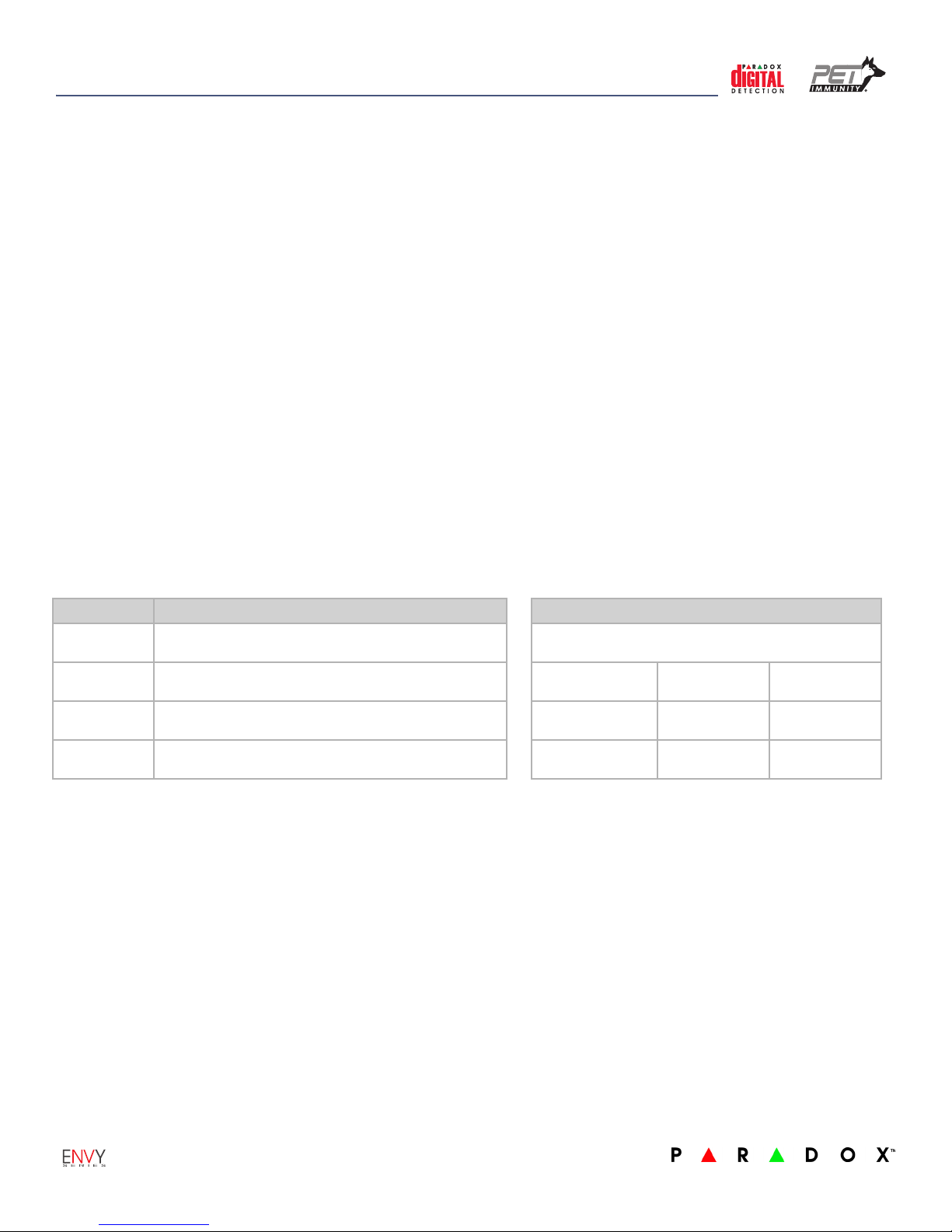
Detector Settings
IMPORTANT: When changing DIP switch settings, the unit must be powered. To save changes, trigger the box tamper or close the cover.
DIP Switch# Functionality Min. and Max. Detection Coverage
DIP Switch 1 LED
Enable (ON) or disable (OFF) the LED, (default = ON)
DIP Switch 2 Buzzer
Enable (ON) or disable (OFF) the buzzer, (default = OFF)
DIP Switch 3 Sensitivity (see table at right)
ON= 100% (High), OFF= 75% (Normal), (default =OFF)
DIP Switch 4 Zone Mode: Single/Dual
ON= Single Mode, OFF= Dual Mode, (default =ON)
The following is the minimum and maximum detection
coverage when the vertical beam adjustment is set at 0°.
75% Sensitivity
Level
100% Sensitivity
Level
Minimum
Coverage
0.4m (1.3 ft.) 11m (36 ft.)
0.1m (0.3 ft.) 23m (75.4 ft.)
Maximum
Coverage
Power-up Sequence
If the module is set in Single Mode:
• Both left and right LEDs blink simultaneously 4 times
• Buzzer activates (on/off beep: one tone)
If the module is set in Dual Mode:
• Both left and right LEDs blink alternately 4 times
• Buzzer activates (two tones, continuous)
Energy Save Mode
The NVR780 enters into Energy Save Mode after two detections within 5 minutes. In Energy Save Mode, both the LED
indication and buzzer indication are shorter than during normal operation. After 3 minutes, the module returns to transmission mode.
Battery Replacement
Replace the pack in its original orientation; the batteries must be facing up (towards PCB enclosure), and the connector must be on the left side.
Alarm
If the module is set in Single Mode:
• LED: red LED indication only on the relevant side(s) for 2 sec.
• Buzzer: activates (same tone for each side)
If the module is set in Dual Mode:
• LED: red LED indication only on the relevant side(s) for 2 sec.
• Buzzer: activates, each side has its own tone. If there is an alarm
on both sides, there is a separate, third tone.
Firmware Upgrade via Built-in Serial Port
For upgrade instructions, refer to the Firmware Upgrade Instructions document which is available at paradox.com > Software > WinLoad.
NVR780-EI04 Printed in Canada 02/2012
Page 2
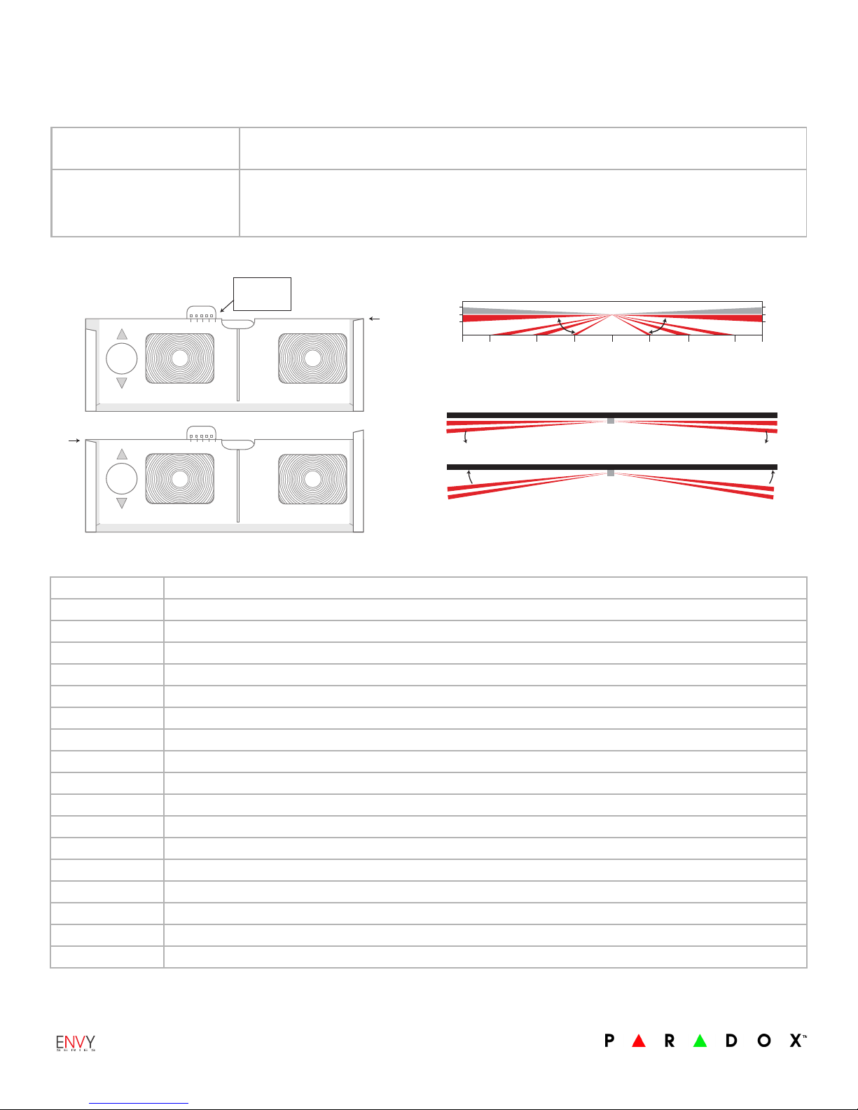
Adjustable Beam Pattern
0°5°10°
15°
20°
0°
0° = 12m
20° = 3m
(Horizontal)
B
(Vertical)
A
2m/6.6 ft~
1m/3.3 ft~
1.5m/4.9 ft
12m
10m
12m
10m
6m
6m
3m
3m
0
2m/6.6 ft~
1m/3.3 ft~
1.5m/4.9 ft
0 degrees
0 degrees
Wall (Top View)
0 degrees position
3 degrees position
3 degrees
3 degrees
Wall (Top View)
3°
C
0°5°10°
15°
20°
A: Vertical Beam Adjustment
(lower beam only)
Adjust the vertical beam by sliding the lens tab vertically (see A in Figure 2), and locking the lens tab in the
desired position, where: 0° = 12m, 5° = 10.5m, 10° = 7.5m, 15° = 5.25m, 20° = 3m.
B and C: Horizontal Beam
Adjustment
Adjust the horizontal beam by sliding the lens casing horizontally, and aligning its top edge with either the
upper railing, (see B in Figure 2), or aligning its top edge with the lower railing (see C in Figure 2).
Lens casing aligned with upper railing = 0°
Lens casing aligned with lower railing = 3°
Figure 2: Adjustable Beam Pattern
Vertical Beam Adjustment
Horizontal Beam Adjustment
The NV780 features an adjustable beam pattern, both vertically and horizontally. The vertical adjustment is made to extend or shorten the range
of detection; each lower beam can be independently adjusted between five positions (0° = 12m, 5° = 10.5m, 10° = 7.5m, 15° = 5.25m, 20° = 3m).
The horizontal adjustment is made to avoid detection of unwanted objects directly next to the detector (0° or 3° away from wall).
39.4 ft
32.8 ft
19.7 ft
9.8 ft
9.8 ft
19.7 ft
32.8 ft
39.4 ft
Technical Specifications
Sensor 4x dual rectangular element, low noise, high sensitivity, EMI immunity
Lens 2nd gen., flat, 2x dual beam, 1.7” focal point, narrow beam long-range Fresnel lens
Processing High resolution digital signal processing / digital APSP / true digital temperature compensation / ultra low current-saving algorithm
Startup time 35 sec.
Detection speed 0.2m/sec – 4m/sec (0.6’ – 13.1’ft/sec)
Power input 3x AA alkaline battery
Current consumption 3 year battery life
Coverage Bi-directional, independent, 2 x 3m to 12m (9.8ft to 39ft)
PET Immunity Up to 40kg (90lb) - requires min.1.5m (4.9ft) installation height
Installation height 1.5m and above
Alarm indicator 2x red LED for 2 sec., 1 for each detection side + buzzer (can be disabled)
Alarm output Configured as two independent zones or a single zone
Anti-tamper switch Box and wall tamper detection and messages
Operating temperature -35°C to +50°C (-31°F to +122°F)
Humidity 95% max.
Dimensions 9 x 5.5 x 4 cm (3.5 x 2.2 x 1.6 in.)
RF frequency 433MHz or 868MHz
RF immunity Complies with EN 50130-4: 10V/m 80MHz to 2GHz
Patents : One or more of the following US patents may apply: 7046142, 6215399, 6111256, 6104319, 5920259, 5886632, 5721542, 5287111, and RE39406 and other pending patents may apply. Canadian and international patents may also
apply. Trademarks: Paradox is a trademark of Paradox Security Systems Ltd. or its affiliates in Canada, the United States and/or other countries. Certification: For the latest information on products approvals, please visit www.paradox.com.
Warranty: For complete warranty information on this produ ct please refer to the Limited Warranty Statement found on the website www.paradox.com/terms. © 2012 Paradox Ltd. All rights reserved. Specifications may change without prior
notice.
NVR780-EI04 Printed in Canada 02/2012
 Loading...