

Page 1
K07C: Grafica Color Keypad
V1.0
Reference and Installation Manual
Page 2

Warranty
For complete warranty information, please visit www.paradox.com/terms.
Your use of the Paradox product signifies your accept ance of all warranty
terms and conditions. Imperial, Grafica, BabyWare, EVO and WinLoad
are trademarks or registered trademarks of Paradox Security Systems
Ltd. or its affiliates in Canada, the United States and/or other countries.
For the latest product approvals, such as UL and CE, please visit
www.paradox.com. © 2009 Paradox Security Systems Ltd. All rights
reserved. Specifications may change without prior notice.
Patents
One or more of the following US patents may apply: 7046142, 6215399,
6111256 , 6104319, 5920259, 5886632, 5721542, 5287111, 5119069,
5077549 and RE39406 and other pending patents may apply. Canadia n
and international patents may also apply.
Page 3

Table of Contents
Overview ................................................................ 5
Description .............................................................................. 5
Features.................................................................................. 5
Installation .............................................................. 6
Viewing Angle.......................................................................... 6
Keypad Cover Clearance........................................................ 6
Mounting the Metal Wall Plate................................................. 7
Connecting Grafica.................................................................. 7
Keypad Input........................ .......................................... ......... 9
Temperature Sensors.............................................................. 9
Mounting Grafica................................................................... 10
Removing Grafica.................................................................. 11
Firmware Upgrade................................ ... .............................. 12
Imperial System Programming ............................... 12
EVO/DGP System Programming............................. 12
Entering Module Programming Mode.................................... 13
Programming Methods.................... ...................................... 13
Feature Select Programming ..................... ... ........................ 13
Decimal Programming..................... ... ................................... 13
Hexadecimal Programming................ .. ................................. 13
Keypad Options...................... .......................................... ... .. 14
Temperature Broadcast......................................................... 18
EVO/DGP Programming Sections......................................... 20
Page 4

Specifications
Power input Typically 12 to 16 Vdc
Current
consumption
120 mA (at maximum backlight setting)
Number of inputs 1
Temperature
sensors
1 built-in, 1 optional external temperature sensor
(TEMP07)
Locate indication Blue LED flashes
Multibus/Combus
fault indication
Fault indication message will appear on the LCD screen.
Anti-tamper switch Yes (optional)
Display TFT screen (Thin Film Transistor). Under electrostatic-
discharge (ESD) conditions the screen may go blank. To
reset the screen press any key or wait one minute.
Screen size: 9cm (3.5”)
Screen resolution: 320x240
Colors: 64k colors
Compatibility Imperial V32
EVO48/192
DGP-NE96
DGP-848
NOTE:
Imperial systems require BabyWare V1.0.300 and
higher. Refer to the Imperial System Guide.
Page 5
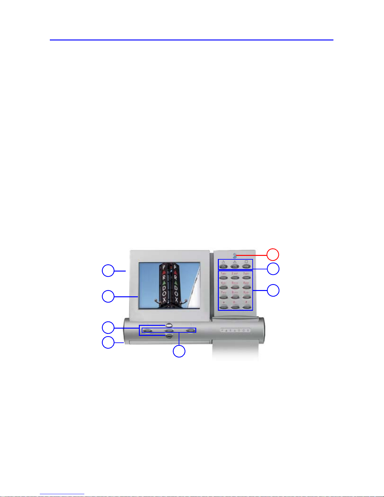
Overview PAGE 5
Chapter 1: Overview
1. SD memory card slot
2. Color LCD screen
3. Scroll keys - navigation
4. Temperature sensor
5. Action keys - selection
6. Panic keys
7. Alphanumeric keys
A) Power light:
On = AC power
Off = Power failure
Flash = System is locating the
keypad
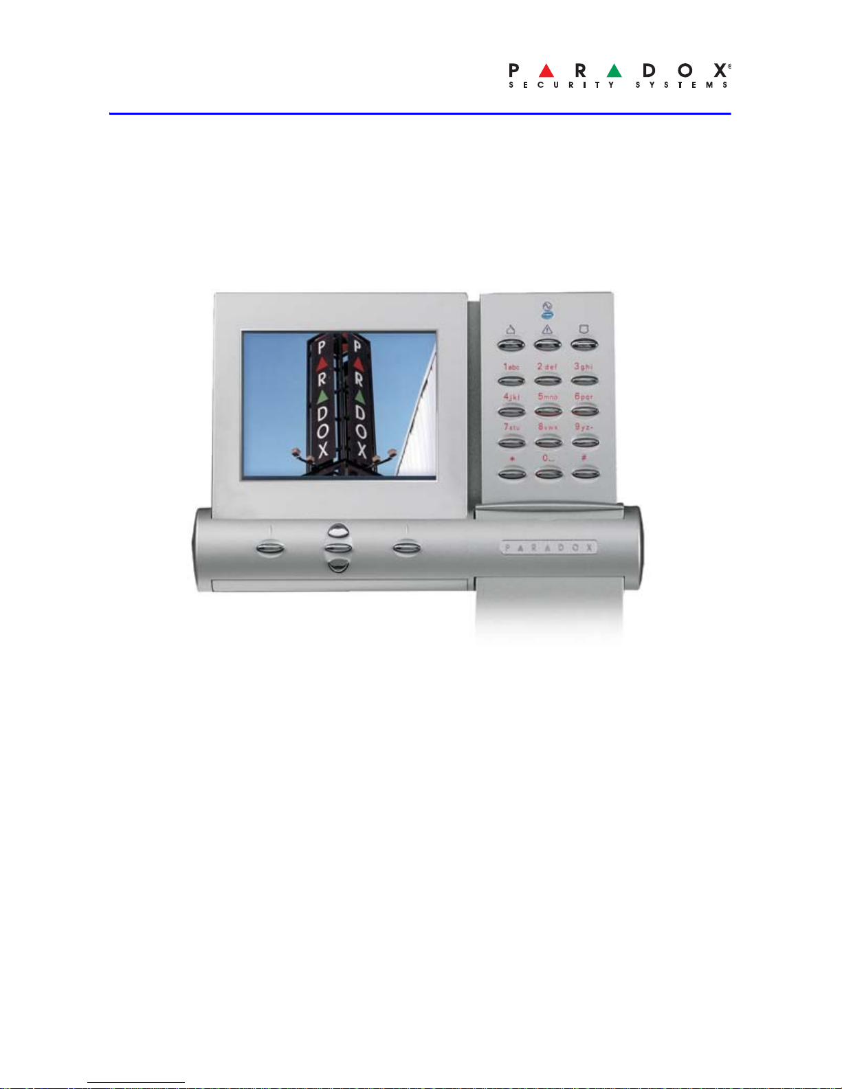
Description
Grafica sets a new milestone for
keypads in the security industry.
With its full color LCD screen,
Grafica offers the unique ability to
view zone locations on floor plan
drawings.
Other features include a photo
screensaver, downloadable tunes
and bitmaps for many functions, a
smart search engine for users and
zones, and an alarm clock.
Features
• Photo screensaver
• Downloadable tunes and
bitmaps
• Smart search engine for users
and zones
• Alarm clock
• Indoor temperature sensor
• Outdoor temperature sensor
(optional)
• 14 one-touch action buttons
• 3 keypad-activated panic
alarms
• Adjustable backlight and
volume
4
6
7
5
3
2
A
1
Page 6
PAGE 6 Installation
Chapter 2: Installation
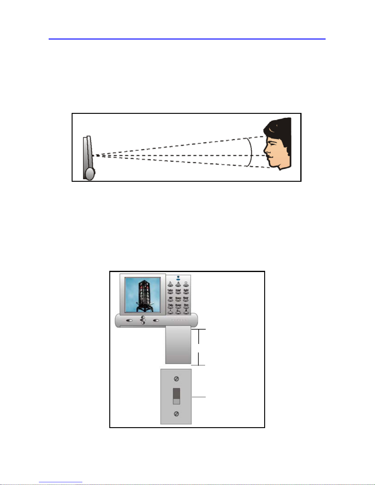
Viewing Angle
Grafica’s graphic LCD screen is best viewed from an angle between 20°
and -10° (see Figure 1). Be sure to install the Grafica keypad at a height
and in a direction that provides the best viewing angle.
Figure 1
Keypad Cover Clearance
Grafica’s keypad cover requires sufficient space in order to open
properly. Ensure a clearance of approximately 9cm (3.5in) between the
bottom of the keypad and possible obstructions such as a light switch
that may prevent the keypad from opening properly (see Figure 2).
Figure 2
-10°
0°
+20°
A
- 9cm (3.5”)
B
- Obstruction
A
B
Page 7
Installation PAGE 7
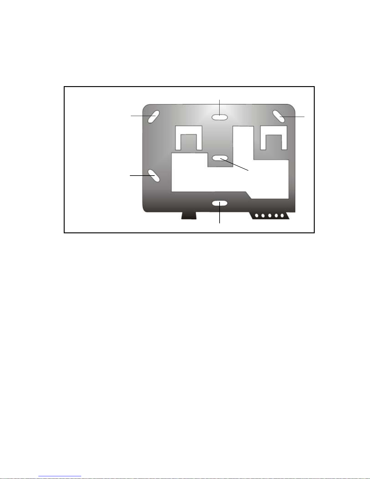
Mounting the Metal Wall Plate
1. Place metal wall plate to desired position.
2. Drill and insert screws into holes labeled “A” (see Figure 3). Both the
top and bottom center holes “C” can be used for an electrical box.
Figure 3
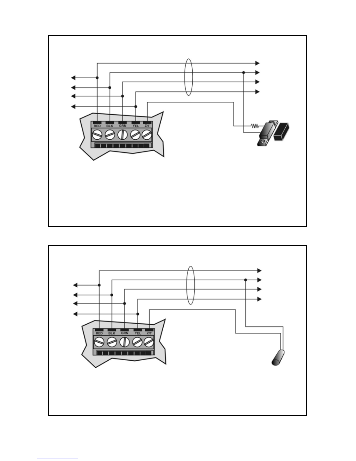
Connecting Grafica
Grafica connects to the control panel’s Multibus/Combus in a star and/or
daisy chain configuration. The Multibus/Combus consists of four wires
that provide power and two-way communication betwe en the control
panel and all modules connected to it. Connect the four terminals
labelled
RED, BLK, GRN and YEL of the module to the corresponding
terminals on the control panel (see Figure 4 on page 8). For the
maximum allowable installation distance, refer to the Imperial System
Guide or the EVO/DGP Reference & Installation Manual.
A
A A
C
C
A
- Mounting holes
B
- For clip
C
- Can be used for
electrical box
B
Page 8
PAGE 8 Installation
Figure 4
Figure 5
A
- * The keypad zone follows the control panel’s EOL definition. The zone speed is set
at 600mS and cannot be programmed.
Grafica
B
C
Multibus/
Combus
1 K9*
EOL
Connecting Grafica with Keypad Input
A
- To other modules
B
- To control panel
C
- Door Contact
A
- To other modules
B
- To control panel
C
- Temperature Sensor (TEMP07)
Grafica
A
B
C
Multibus/
Combus
Connecting Grafica with Temp. Sensor
30.5m (100ft) max.
Page 9
Installation PAGE 9
Keypad Input
Grafica’s keypad input can be utilized as a zone input or as an input for
the optional temperature sensor (see Optional External Temperature
Sensor). Refer to Figure 5 on page 8 for connection instructions.
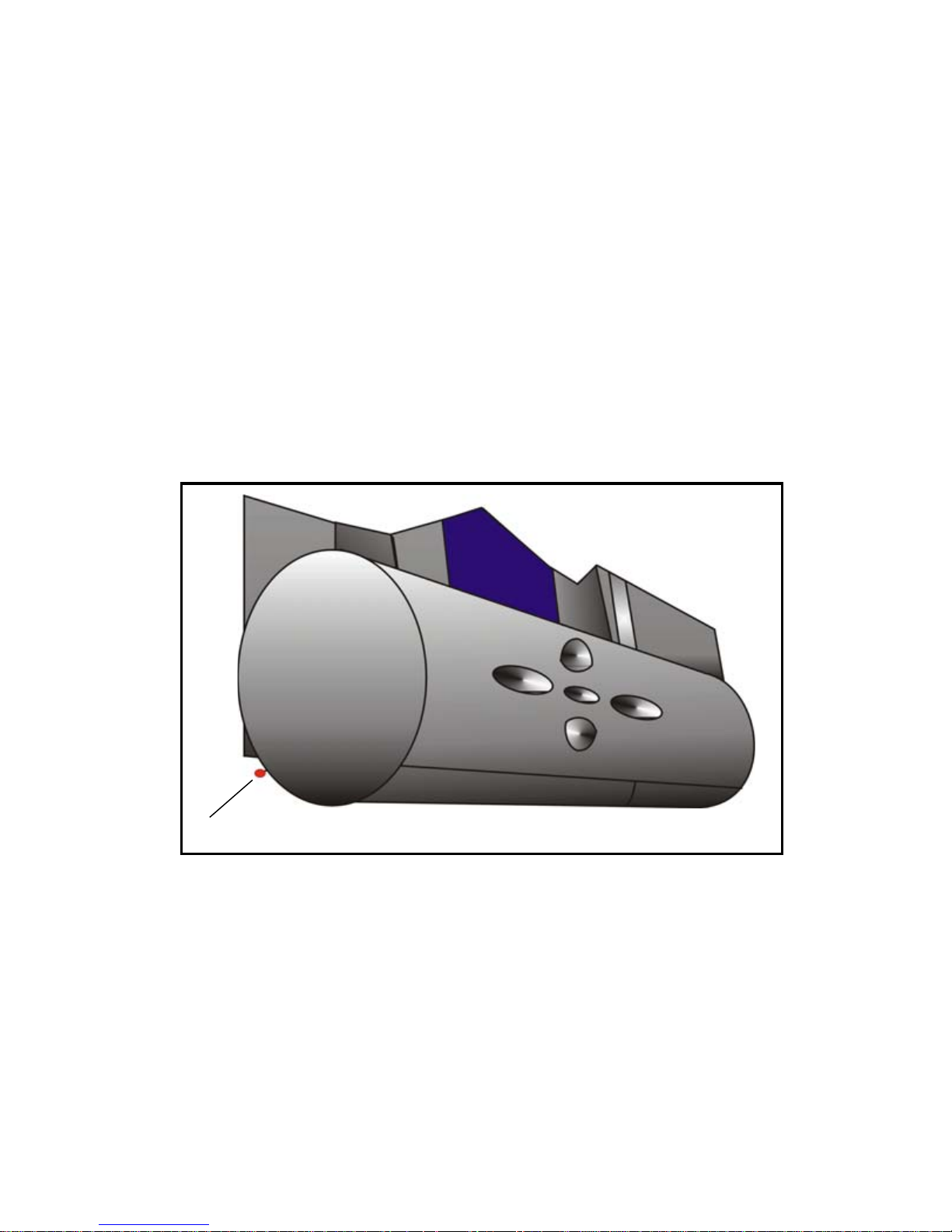
Temperature Sensors
Grafica offers a built-in temperature sensor and an optional external
temperature sensor.
Built-in Temperatur e Sens o r
If the Inside Temp. ON option is enabled, the built-in temperature
sensor’s (see Figure 6) reading will displ ay on the System Status
screen next to the word “IN”. If another temperature sensor is
required, see Optional External Temperature Sen so r.
Figure 6
Optional External Temperature Sensor
Grafica offers an optional external temperature sensor (TEMP07)
that connects to Grafica’s keypad input (see Keypad Input). If the
Outside Temp. ON option is enabled, the sensor’s reading will display
on the System Status screen next to the word “OUT”.
Built-in Temperature Sensor
Page 10

PAGE 10 Installation
Mounting Grafica
1. Place Grafica’s back plate flush against the mounted metal wall plate
“B” (see Figure 7).
Figure 7
2. Slide Grafica’s open slots labeled “A” (see Figure 8) onto the metal
wall plate’s tabs labeled “A” (see Figure 7).
Figure 8
3. Gently apply downward pressure to snap Grafica onto the metal wall
plate.
A
- Metal wall plate tabs
B
- Metal wall plate
C
- Optional screw
A
B
C
A
A
Clip
Grafica back view
Page 11

Installation PAGE 11
4. You may insert the optional screw “C” under the Grafica keypad
through the space in the metal wall plate’s left tab (see Figure 7 on
page 10).
Removing Grafica
1. If required, remove the optional screw (see Figure 7 on page 10).
2. Gently slide the unit upwards with your hands until it separates from
the metal wall plate (see Figure 9).
Figure 9
Figure 10
A
A
- Metal wall plate
Grafica
(partial view)
Used with EVO/DGP panels only
(307USB and Memory Key connections)
Page 12

PAGE 12 Imperial System Programming
Firmware Upgrade
Imperial Systems
The K07C is firmware upgradeable remotely via th e V32 controller’s
Multibus at 57.6Kbps. Using BabyW are connect to the V32 account
using any of the connection methods (direct connect, IP static, or IP
DNS). Right-click the desired module and se lect Upgrade. When
communicating through the Internet, BabyWare will indicate whether
the panel or any of the bus modules have a newer firmware version
available. A firmware upgrade for a single module or group of
modules will take usually less than 10 minutes, which keeps system
downtime to a minimum.
EVO/DGP Systems
Upgrade Grafica’s firmware version using the 307USB Direct
Connect Interface (see 4-pin connection in Figure 10 on page 11)
and In-Field Paradox Upgrade Software. For firmware upgrade
instructions, go to paradox.com > Software >WinLoad, and locate the
Firmware Upgrade Instructions document.
NOTE: You must first disconnect the keypad’s GRN and YEL
combus wires before following instructions.
Chapter 3: Imperial System Programming
For Imperial systems, all Grafica programming and options are set using
BabyWare software. For more information, refer to the BabyWare
instructions in the Imperial System Guide.
NOTE: Floor plans, tones and graphics can be downloaded to Grafica
using BabyWare.
Chapter 4: EVO/DGP System Programming
For EVO and DGP systems, Grafica programming is done through the
panel’s Module Programming Mode. Grafica can also be programmed
using the WinLoad Installer Upload/Download Software. For more
information, refer to the WinLoad instructions or visit our Web site at
www.paradox.com. We strongly recomme nd that you read this entire
manual before you begin programming.
NOTE: Floor plans, tones and graphics can be downloaded to Grafica
using WinLoad V2.6 or higher and NEware V2.0 or higher.
Page 13

EVO/DGP System Programming PAGE 13
Entering Module Programming Mode
Like all other keypads in the system, Grafica is programmed through the
control panel. To do so, you must enter the panel’s Module Programming
Mode:
1. From Normal Mode press and hold the [0] key.
2. Enter the [
INSTALLER CODE] (by default 000000).
3. Enter section [4003].
4. Enter Grafica’s 8-digit [
SERIAL NUMBER].
5. Enter the 3-digit [
SECTION] you want to program.
6. Enter the required [DATA].
The control panel will then redirect all programming to the selected
Grafica keypad. Use the scroll and action keys (see Figure 1 on page 6)
to navigate through desired sections.
NOTE: The keypad’s serial number is located on the PCB, or enter
section [0000] in step 3 to view Grafica’s version and serial number.
Programming Methods
The following methods can be used when programming the Grafica
keypad:
Feature Select Programming
You can program sections by enabling or disabling op tions. Within
these sections, keys [1] to [8] or scroll keys represent a specific
Grafica option. Use the scroll keys to highlight the desired option and
press the corresponding action key to enable or di sable the option.
An “X” will appear to indicate that the option is enabled. Press the
appropriate action key to save the status of the selected options.
Decimal Programming
Some sections require the entry of a decimal value. For this method,
any value from 000 to 255 can be entered.
Hexadecimal Programming
Some sections require the entry of hexadecimal values A to F. Press
the [#] key to scroll through these values. If the value is left
unchanged for two seconds, Grafica will automatically select it and
move forward to the next digit.
Page 14

PAGE 14 EVO/DGP System Programming
Keypad Options
The following sections detail Grafica’s programing options for EVO/DGP
systems.
Partition Assignment
SECTION [001]: OPTIONS [1] TO [8]
Each keypad in the system can be assigned to one or more
partitions. In section [001], options [1] to [8] represent partitions 1
through 8 respectively . To assign the keypad to a partition, enable the
option that corresponds to the desired pa rtition. By default, partitions
1 to 8 are enabled.
NOTE: Options [5] to [8] are not available with DGP-848 systems.
Display Code Entry
SECTION [002]: OPTION [1]
This option determines whether the user’s code # (PIN) is displayed
on the LCD screen when entering the PIN.
Option [1] OFF = Digits are replaced by asterisks (*) (default)
Option [1] ON = Code # (PIN) digits will be displayed
Display Exit Delay
SECTION [002]: OPTION [2]
Based on the user's needs, an Exit Delay Timer can be programmed
to provide the user time to exit the p artition before the system is
armed. If this option is enabled, the Exit Delay T imer's countdown will
appear on the LCD screen next to the hourglass icon.
Option [2] OFF = Exit delay time will not appear
Option [2] ON = Exit delay time will appear (default)
Display Entry Delay
SECTION [002]: OPTION [3]
Based on the user's needs, an Entry Delay Timer can be
programmed to provide the user time to enter their code # (PIN)
before the alarm is triggered. If this option is enabled, the Entry Delay
Timer's countdown will appear on the graphic LCD screen next to the
hourglass icon.
Option [3] OFF = Does not display Entry Delay Timer
Option [3] ON = Displays Entry Delay Timer (default)
Page 15

EVO/DGP System Programming PAGE 15
Confidential Mode
SECTION [002]: OPTIONS [4] AND [5]
WARNING: For UL installations, Confidential Mode must be disabled
(option [4] = OFF)
If Confidential Mode is enabled and actions are not performed on the
Grafica keypad for a period of time, the screen will display the time,
date and all LEDs on the keypad will turn off until either a key is
pressed, or an code # is entered. The period of time in which no
action is performed is defined by the Confidential Mode Timer (see
“Confidential Mode Timer” on page 17).
Grafica will switch from Confidential Mode to Normal Mode when a
key is pressed or a code # (PIN) is entered. In normal mode, Grafica
displays the date, time and the status of the zones for every partition
assigned to the keypad. In addition, the alarm memory, bypassed
zones and troubles will also be displayed.
S
ECTION [002]: OPTION [4]
Option [4] OFF = Normal Mode (default)
Option [4] ON = Confidential Mode
S
ECTION [002]: OPTION [5]
Option [5] OFF = Exit confidential mode by entering an code # (PIN)
(default)
Option [5] ON = Exit confidential mode by pressing any key
NOTE: Section [002] option [5] will work onl y if option [4] in section
[002] is enabled.
Exit Delay Beep
SECTION [002]: OPTION [6]
The keypad can beep once every second or play a selected tone
during the Exit Delay Timer. During the final 10 seconds only the
beep tone will be heard (at a faster interval) to provide a final warning
before the area is armed.
Option [6] OFF = Exit Delay beep is disabled
Option [6] ON = Exit Delay beep is enabled (default)
Keypad Input Type
SECTION [002]: OPTION [7]
Grafica’s keypad input (see “Keypad Input” on pa ge 9) can be utilized
as a zone or as an input for an optional external temperature sensor
Page 16

PAGE 16 EVO/DGP System Programming
(see “Optional External Temperature Sensor” on page 9). If set as a
temperature input, Grafica represents it as the outside temperature
on the System Status screen next to the word “OUT”.
Option [7] OFF = Temperature sensor input (default)
Option [7] ON = Zone input
Keypad Tamper
SECTION [002]: OPTION [8]
When the keypad tamper option is enabled and the keypad's antitamper switch (optional) is triggered, the keypad will send a Tamper
report to the control panel via the combus.
Option [8] OFF = Grafica’s tamper option is disabled (default)
Option [8] ON = Grafica’s tamper option is enabled
Beep on Trouble
SECTION [003]: OPTIONS [1] TO [4]
Potential troubles have been sorted into groups. With these options
enabled, the keypad will emit an intermittent beep tone whenever a
trouble condition occurs from one of the trouble groups. The
intermittent beep will remain activated until the user enters Grafica’s
Trouble Display or if the trouble is resolved. For a list of troubles, see
the appropriate control panel’s Reference and Installation Manual.
The intermittent beep will be re-initialized whenever the trouble
condition reoccurs.
System and Clock Trouble Beep
SECTION [003]: OPTION [1]
O
ption [1] OFF = Beep disabled (default)
Option [1] ON = Be ep on: System Troubles and Clock Loss
Communicator Trouble Beep
SECTION [003]: OPTION [2]
Option [2] OFF = Beep disabled
Option [2] ON = Beep on : Communicator Troubles (default)
Module and Combus Trouble Beep
SECTION [003]: OPTION [3]
Option [3] OFF = Beep disabled (default)
Option [3] ON = Beep on: Module and Combus Troubles
Page 17

EVO/DGP System Programming PAGE 17
All Zone Trouble Beep
SECTION [003]: OPTION [4]
Option [4] OFF = Beep disabled (default)
Option [4] ON = Beep on: All Zone Troubles
Time Format
SECTION [003]: OPTION [7]
Option [7] OFF = 24 hour format (default)
Option [7] ON = 12 hour format: AM/PM
Date Format
SECTION [003]: OPTION [8]
Option [8] OFF = Date format: yy-mm-dd (default)
Option [8] ON = Date format: dd-mm-yy
Confidential Mode Timer
SECTION [004]
Section [004] determines the amount of time that must elapse
without performing an action on the keypad before the keypad enters
Confidential Mode (see “Confidential Mode” on page 15). The
Confidential Mode Timer can be any value from 005 to 255 seconds
(default: 120 seconds).
Temperature Calibration
SECTION [005] = OUTSIDE TEMPERATURE CALIBRATION
SECTION [006] = INSIDE TEMPERATURE CALIBRATION
The outside temperature reading is that given by the optional
external temperature sensor (see “Optional External Temperature
Sensor” on page 9) when connected to Grafica’s input. The inside
temperature reading is that given by Grafica’s built-in temperature
sensor (see “Built-in Temperature Sensor” on page 9). If the
temperature reading is inaccurate, enter a calibration value in the
corresponding section to adjust the reading. Enter a value between
000 to 254 (000 and 128 = no calibration value). When in Celsius,
every value from 001 to 127 adds .5 degrees, and every value from
129 to 254 subtracts .5 degrees, to the temperature display. When in
Fahrenheit, every value from 001 to 127 adds 1 degree, and every
value from 129 to 254 subtracts 1 degree, to the temperature display.
Page 18

PAGE 18 EVO/DGP System Programming
Temperature Broadcast
Using sections [007] to [01 1], you can define which temperature readings
are used for which purpose. For example, a Grafica keypad is installed in
the main house as well as the guest house. The indoor temperature from
the guest house keypad can be displayed as the outdoor temperature of
the main house keypad, allowing you to monitor the indoor temperatures
of both buildings.
Indoor Temperature From Another Grafica
SECTION [007]: OPTION [1]
Option [1] OFF = Disabled (default)
Option [1] ON = Enabled
NOTE: Use this section in conjunction with sections [008] and [009].
Outdoor Temperature From Another Grafica
SECTION [007]: OPTION [2]
Option [2] OFF = Disabled (default)
Option [2] ON = Enabled
NOTE: Use this section in conjunction with sections [010] and [011].
Send Indoor/Outdoor Temp. to Other Grafica Keypads
SECTION [007]: OPTION [4]
Option [4] OFF = Disabled (default)
Option [4] ON = Enabled
For Indoor Temp., Import all Temp. Data From:
SECTION [008]
When section [007] option [1] is enabled, enter the serial nu mber of
the Grafica keypad from which you would like to import temperature
data.
Which Imported Temp. Value is Displayed as Indoor
Temp.
SECTION [009]
When a Grafica serial number is entered in section [008], the
keypads indoor and outdoor temperatures are sent. Select which
incoming value will be displayed as the keypad’s indoor temperature.
Indoor temperature = (001)
Outdoor temperature = (002)
Page 19

EVO/DGP System Programming PAGE 19
For Outdoor Temp., Import all Temp. Data From:
SECTION [010]
When section [007] option [2] is enabled, enter the serial nu mber of
the Grafica keypad from which you would like to import temperature
data.
Which Imported Temp. Value is Displayed as Outdoor
Temp.
SECTION [011]
When a Grafica serial number is entered in section [010], the
keypads indoor and outdoor temperatures are sent. Select which
incoming value will be displayed as the keypad’s outdoor
temperature.
Indoor temperature = (001)
Outdoor temperature = (002)
Page 20

PAGE 20 EVO/DGP System Programming
EVO/DGP Programming Sections
* Must be enabled through option [4] in section [002] first.
Section [001]: Keypad Partition Assignment
Option OFF ON
[1] Partition 1 NDisabled UEnabled
[2] Partition 2 NDisabled UEnabled
[3] Partition 3 NDisabled UEnabled
[4] Partition 4 NDisabled UEnabled
[5] Partition 5 NDisabled UEnabled
[6] Partition 6 NDisabled UEnabled
[7] Partition 7 NDisabled UEnabled
[8] Partition 8 NDisabled UEnabled
Section [002]: General Options 1
Option OFF ON
[1] Display code entry UDisabled NEnabled
[2] Display exit delay NDisabled UEnabled
[3] Display entry delay NDisabled UEnabled
[4] Confidential mode UDisabled NEnabled
[5] To exit confidential mode * UEnter
Code
NPress key
[6] Exit delay beep NDisabled UEnabled
[7] Keypad input type UTemp.
Sensor
NZone
[8] Keypad tamper UDisabled NEnabled
U= Default Setting
Page 21

EVO/DGP System Programming PAGE 21
Default Setting: 120 seconds
Section [003]: Beep on Trouble
Option OFF ON
[1] System & clock trouble beep UDisabled NEnabled
[2] Communicator trouble beep UDisabled NEnabled
[3] Module & combus trouble beep UDisabled NEnabled
[4] All zone trouble beep UDisabled NEnabled
[5] Future use N-- N--
[6] Future use N-- N--
[7] Time format 24h / AM PM U24h NAM /PM
[8] Date display Uyy-mm-dd Ndd-mm-yy
Section [004]: Confidential Mode Timer
Data ___/___/___ (005 to 255 seconds)
Section [005]: Outside Temperature Calibration
Data ___/___/___ (001 to 254; 000 and 128 = no calibration
value)
Section [006]: Inside Temperature Calibration
Data ___/___/___ (001 to 254; 000 and 128 = no calibration
value)
Page 22

PAGE 22 EVO/DGP System Programming
Section [007]: Temperature Options
Option OFF ON
[1] Indoor temperature from another
Grafica
UDisabled NEnabled
[2] Outdoor temperature from
another Grafica
UDisabled NEnabled
[3] Future Use NN/A NN/A
[4] Send indoor / outdoor
temperature to other Grafica
keypads
UDisabled NEnabled
[5]-[8] All Zone Trouble Beep NN/A NN/A
Section [008]: For Indoor Temp., Import all Temp. Data From:
Data __/__/__/__/__/__/__/__ (Another Grafica’s serial #)
Section [009]: Which of the Imported Temp. Values Will be
Displayed as Indoor Temp.
Data ___/___/___ (001 = Internal / 002 = External)
Section [010]: For Outdoor Temp., Import all Temp. Data From:
Data __/__/__/__/__/__/__/__ (Another Grafica’s serial #)
Section [011]: Which of the Imported Temp. Values Will be
Displayed as Outdoor Temp.
Data ___/___/___ (001 = Internal / 002 = External)
Section [100]: Download From Memory Key
Download data from memory key
Section [110]: Copy to Memory Key
Upload data to memory key
Page 23

EVO/DGP System Programming PAGE 23
Index
Numerics
12/24 hour time .............................................................................. 17
A
All zone trouble beep .....................................................................17
AM/PM
........................................................................................... 17
B
Beep ........................................................................................16, 17
Beep - exit delay ............................................................................15
Beep on trouble .............................................................................16
C
Clock trouble beep ......................................................................... 16
Code entry
..................................................................................... 14
Combus trouble beep ..................................................................... 16
Communicator trouble beep ........................................................... 16
Confidential mode
.......................................................................... 15
Confidential mode timer ................................................................. 17
Connections ..................................................................................... 7
Cover clearance
............................................................................... 6
D
Date format .................................................................................... 17
Decimal programming .................................................................... 13
DGP-848
........................................................................................ 14
Display code entry ......................................................................... 14
Display exit delay ........................................................................... 14
E
Entry delay ..................................................................................... 14
EOL definition
.................................................................................. 8
EVO/DGP systems ........................................................................ 12
Exit delay ....................................................................................... 14
Exit delay beep
.............................................................................. 15
Page 24

PAGE 24 EVO/DGP System Programming
F
Feature select programming .......................................................... 13
Firmware upgrade .......................................................................... 12
H
Hexadecimal programming ............................................................ 13
Hourglass icon ............................................................................... 14
I
Imperial systems ............................................................................ 12
Indoor temperature
........................................................................ 18
Input ................................................................................................. 9
Input type ....................................................................................... 15
Installation hei gh t
............................................................................. 6
K
Keypad clearance ............................................................................6
Keypad Input .................................................................................... 9
Keypad input type
.......................................................................... 15
Keypad options .............................................................................. 14
Keypad tamper .............................................................................. 16
M
Metal wall plate ................................................................................ 7
Module programming mode
........................................................... 13
Module trouble beep ...................................................................... 16
Mounting ....................................................................................7, 10
O
Outdoor temperature ...................................................................... 18
Overview
.......................................................................................... 5
P
Partition .......................................................................................... 14
Partition assignment ...................................................................... 14
Programming methods ...................................................................13
Programming mode
....................................................................... 13
Programming sections ................................................................... 20
Page 25

PAGE 25
R
Removing Grafica .......................................................................... 11
S
Sections ......................................................................................... 20
Specifications ................................................................................... 4
System trouble beep ...................................................................... 16
T
Tamper .......................................................................................... 16
Temperature - indoor/outdoor
........................................................ 18
Temperature broadcast .................................................................. 18
Temperature calibration ................................................................. 17
Temperature sensor
......................................................................... 9
Time format .................................................................................... 17
Trouble - beep
............................................................................... 16
U
UL installations ............................................................................... 15
Upgrade firmware .......................................................................... 12
Uploading/downloading data .......................................................... 19
V
Viewing angle .................................................................................. 6
W
Wall plate ......................................................................................... 7
Wiring
............................................................................................... 7
Z
Zone trouble beep .......................................................................... 17
Page 26

Page 27

Page 28

K07C-EI00 06/2009 PARADOX.COM Printed in Canada
For technical support in Canada or the U.S., call 1-800-791-1919,
Monday to Friday from 8:00 a.m. to 8:00 p.m. EST. For technical support
outside Canada and the U.S., call 00-1-450-491-7444, Monday to Friday
from 8:00 a.m. to 8:00 p.m. EST.
Please feel free to visit our website at www.paradox.com.
 Loading...