

Page 1
IP150 Internet Module
User Guide V1.3 - IP150-EU01
Printed in Canada 07/2013
Introduction
The IP150 Internet Module is an Internet communication module that enables you to control and
monitor your security system through any web browser (e.g. Internet Explorer). The IP150 provides
freedom to access your system and receive email notifications anywhere in the world.
IMPORTANT: The IP150 module should only be configured by the installer or a qualified network
administrator. For more information on module configuration, consult the IP150 Reference and
Installation Manual.
Connecting via the IP150 Internet Module
In order to connect to your IP150, you will need the following information:
• Paradox DNS Site ID: The DNS SiteID is set by your installer.
• Panel user code: This is the same code you enter on your keypad to arm the system.
• Module password: The default password is “paradox”. To change your password,
see “Change Password” in the Account Information Screen section.
To connect with your system from an external computer:
1. Open a web browser (e.g., Google Chrome).
2. In the address bar, enter http://www.paradoxmyhome.com/SiteID
where “SiteID” is your Paradox SiteID (set by your installer).
3. Log in using your panel user code and module password (default = paradox).
Troubleshooting
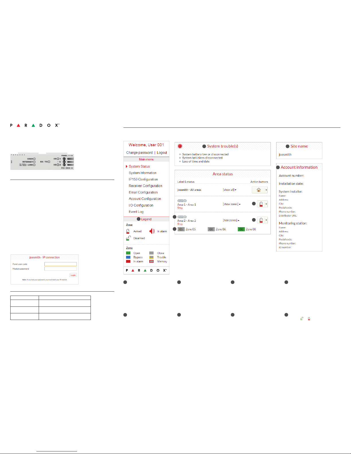
System Status Screen
The System Status screen displays important system information.
From the System Status screen, you can arm / disarm your system as well as monitor your system in real-time.
Once you have
established a
connection for the first
time, you are prompted
to change your
password from the
default “paradox”.
System Troubles
When a trouble occurs in the system,
it is displayed at the top of the System
Status screen.
Note: If there are no troubles in the
system, the System Troubles box
is not displayed.
Area Status
The IP150 provides a real-time display
of your area status.
Zone Status
The IP150 provides a real-time display
of your zone status.
Legend
The Legend gives you information on the
icons shown in the Area Status display.
StayD
The StayD logo appears when StayD
mode is enabled (Spectra SP and
Magellan only).
Site Name
The site name uniquely identifies
your system.
Note: By default, your site name is
“Your Paradox System”.
To change your site name, see “Account
Information Screen” on page 2.
Account Information
For information on changing account
information, see page 2.
Arm / Disarm
Click the or button and select the
arm/disarm action you with to perform.
1
1
2
2
3
3
4
4
6
6
7
7
8
8
5
5
Symptoms Solution(s)
No LEDs lit; no signs of
operation
• Check cable connections
• Check power status
IP150 cannot be
accessed remotely
• Check spelling of access commands
• Check IP and power status on unit
No reporting • Verify panel troubles, panel programming, and /
or receiver status
If the above information does not help remedy the problem, please
contact your installer.
Page 2
Warranty
For complete warranty information on this product, please refer to the Limited Warranty Statement found on the Web site www.paradox.com/terms.
Your use of the Paradox product signies your acceptance of all warranty terms and conditions.
© 2013 Paradox Ltd. All rights reserved. Specications may change without prior notice.
Additional Considerations
Annual verication of timing of an alarm and a fault message is required. ATS5 requirements is the arithmetic mean of all transmissions is less than or equal to 20
seconds and 95% of all transmissions are less than or equal to 30 seconds. Time is measure from the moment the message is reported on a local keypad to when
the monitoring station receiver successfully receives the message. This can be accomplished by contacting the monitoring station and sending a test message
and calculating the time from which the message appears on the local keypad and when the monitoring station receives the same message. As with traditional
land-line reporting an acknowledgement (kiss-off) signal is used when the IP150 sends a valid message to a receiver that is typically used in a monitoring station.
This acknowledgement is generated within 5 seconds. Discuss with your service provider the different options that are available for monitoring; for example, the
frequency of supervision. The transmission of an alarm message may be negatively affected by a variety of factors. These may include disruptions in 3rd party
services like internet access and GSM service. If after a set amount of transmission attempt are unsuccessful local and remote messages are generated. Standard
set of commonly available hand tool are require to install equipment; no equipment adjustments are necessary. When congured as indicated the IP150 surpasses
the ATS5 performace criteria set out in EN 50131-1.
The period from the time a fault develops in the alarm transmission system until the fault information is reported to the alarm receiving centre and/or monitoring
centre shall not exceed 180 seconds for ATS 5 performance criteria as dened by EN 50131-1. This is achieved through settings in the Security Prole of each
account at the receiver equipment. Refer to receiver instruction documentation for further information. As required per clause 7.5 of EN 50136-1-1, records of all
faults and of all performance verifications carried out on the alarm transmission system shall be maintained. Requirements include the availability of these records
for inspection, and availability analysis calculations based on these records. Consult the standard for more detailed information.
1
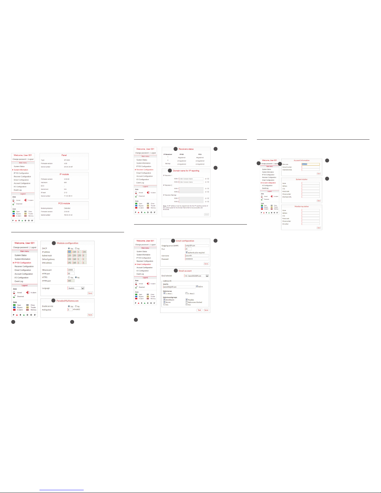
Account Configuration Screen
The Account Conguration screen allows you to store the following information for quick reference:
Account Information
Alarm system installer information
Monitoring station information
Receiver Configuration Screen
The Receiver Configuration screen allows you to configure your module for IP reporting.
1
1
2
3
System Information Screen
The System Information screen contains important hardware and software information on both your
security system, your IP150 module, and if a PCS module. The PCS module section is only visible if a
PCS250/PCS050G module is detected.
3
IP150 Configuration Screen
The IP150 Configuration screen allows you to configure your IP150 Internet Module’s settings.
1
2
Module Configuration
If the IP150 is connected to a server using
a static address, the DHCP protocol is not
necessary. Click “No” and congure the IP150
manually.
1
ParadoxMyHome.com
When ParadoxMyHome.com is enabled,
the DNS service will contact your IP150
module to confirm its current IP address.
With the polling time set to the default
(5 minutes), if the IP150’s IP address
changes, communication will be lost for
up to 5 minutes until the DNS server polls
the IP150. Decreasing the polling time will
result in increased communication between
the IP150 and the Paradox DNS server.
2
Receivers Status
IP150 and PCS module
status information is
displayed.
1
Domain name for IP
reporting
Enter a DNS with a DNS
or DDNS provider (e.g.,
dyndns.com). Also,
enter your DNS in the
section WAN1, WAN2
(e.g., receiver.dyndns.
com). An IP address
must be programmed
into the reporting section
of the control panel for
the Domain Name eld
to be accessible and
functional.
2
Change Password
It is highly suggested that you
change your password from the
default “paradox”.
1
Logout
For security reasons, it is important
to logout when you have finished
monitoring your system.
Note: As an added security feature,
your P150 interface automatically
logs out after it has been inactive
for 5 minutes.
2
1
2
1
2
1
Email Configuration Screen
It is not necessary to be logged in to be kept informed of changes in your system’s status. By selecting Email Configuration from the Main Menu, you can configure the IP150 to send email notifications
to up to 16 email addresses.
1
2
Email Configuration
SMTP Server information
is usually provided by the
Internet Service Provider.
A user name and
password may be
required in order for the
IP150 to access the email
server. This information
can now be entered
into the IP150’s Email
Conguration Screen.
To nd your SMTP
settings (e.g., in Outlook
Express)
1. Click Tools
Accounts
2. Click the Mail tab
Select account
3. Click Properties
Servers tab
1
Email Accounts
To add an email address:
1. Open the Email select drop-down box.
2. Select one of the 16 address locations.
3. Enter the email address in the “Send to” box.
4. Select the areas and events which will
generate an email notification.
5. Click “Save”.
Note: The first Email address (01) is used in the
Email’s “From” eld.
2
Page 3

IP150 Internet Module
Installation Manual V1.3 - IP150-EI01
Printed in Canada 08/2013
Description
The IP150 Internet Module is an HTTPs-supported IP communication device that enables you to
control and monitor your security system through any web browser (e.g., Google Chrome). The
IP150 provides freedom to access your system and receive instant, SSL encrypted email notifications anywhere in the world when your system detects activity. So no matter where you are, you
will have access to arm,
disarm, and more.
Before You Begin
Before you begin, make sure that you have web-enabled computer. You will also require the following system requirements in order to configure to your IP150 Internet Module. System requirements include:
• Ethernet-compatible computer with internet access (required for remote access)
•Router
• 4-pin serial cable (included)
• CAT-5 Ethernet cable (maximum 90m (295 ft.), not included)
• Paradox IP Exploring Tools Software (required for remote access). Software can be downloaded
from our website (www.paradox.com/GSM/IP/Voice/IP).
Figure 1: IP Communication Overview
Connecting and Installing the IP150
Figure 2: IP150 Overview
@
Email Notication
Home PC
Router
Router
Web Access
IPR512
IP Receiver
Monitoring
Station
Control Panel
IP150
WAN
Front View
Right Side ViewLeft Side View
Metal Box Installation
To connect and install the IP150:
1) Connect the 4-pin serial cable between the panel’s serial connector and the IP150’s panel connector (see Right Side View in Figure 2).
2) Connect the Ethernet cable between the router and the IP150’s network connector (see Left
Side View in Figure 2).
3) The onboard LEDs will illuminate to indicate the IP150’s status (see Front View in Figure 2).
4) Clip the IP150 to the top of the metal box (see Metal Box Installation in Figure 2).
LED Indicators
Reset IP150 to Default
To reset the IP150 module to its default settings, insert a pin/straightened paper clip (or similar)
into the pin hole located between the two I/O LEDs. Press down gently until you feel some
resistance; hold it down for approximately 5 seconds, release it when the I/O and RX/TX LEDs start
flashing, and then press it again. The I/O and RX/TX LEDs will remain lit during the reset.
IP Reporting
When using IP reporting, the IP150 has the ability to poll the monitoring station. To enable IP
reporting, the IP150 must first be registered to the monitoring station’s IP Receiver (IPR512). Telephone reporting can be used in conjunction with, or as a backup to IP reporting. Before registering
the IP150, the following information must be obtained from the monitoring station:
• Account number(s) - One account number for each partition used. IP/GPRS reporting uses a
different set of account numbers than those used for dialer reporting.
• IP address(es) - (12-digit number e.g., for 195.4.8.250 you must enter 195.004.008.250)
• The IP address(es) indicate(s) which of the monitoring station’s IP Receivers will be used for IP
reporting.
• IP port(s) (5-digit number; for 4-digit numbers, enter 0 before the first digit). The IP port refers
to the port used by the monitoring station’s IP Receiver.
• Receiver password(s) (up to 32-digits)
• The receiver password is used to encrypt the IP150 registration process.
• Security profile(s) (2-digit number). The security profile indicates how frequently the monitoring
station is polled by the IP150. Security profile numbers and polling frequency are defined by the
monitoring station.
Setting Up IP Reporting
1) Ensure that the panel’s report code format is set to Ademco Contact ID:
MG/SP/E: section [810]
EVO: section [3070]
2) Enter the IP reporting account numbers (one for each partition):
MG/SP/E: section [918] / [919]
EVO: section [2976] to [2983]
3) In the General IP Options section, set up IP line monitoring options and dialer options, and
ensure IP reporting is enabled (see the following tables).
LED Description
User On when a user is connected
Internet
LED Status Internet Connection ParadoxMyHome Enabled
On Connected Connected
Flashing Connected No connection
Off No connection No connection
LED Status Internet Connection ParadoxMyHome Disabled
On Connection No connection
Off No connection No connection
Link Solid Yellow = Valid Link @ 10Mbp;
Solid Green = Valid Link @ 100Mbp;
LED will flash according to data traffic.
Flashing Yellow/Green = DHCP trouble.
Rx/Tx On after first successful communication exchange;
Flashes when data is transmitted or received through/from panel;
Off when no connection has been established.
I/O 1 On when activated
I/O 2 On when activated
MG/SP/E: section [806]
EVO: section [2975]
4) Enter the monitoring station’s IP address(es), IP port(s), receiver password(s), and security
profile(s) (information must be obtained from the monitoring station).
5) Register the IP150 module with the monitoring station. To register, enter the sections below
and press [
ARM]. The registration status is displayed as well as any registration errors.
NOTE: An IP150 used with an MG/SP/E system will always poll using the partition 1 IP account
number. When using an EVO system, the partition 1 IP account is used by default, but can be
defined in section [3020]. All reported system events will originate from the partition selected in
this section.
Remote Access
The IP150 provides remote access to control and monitor a security system via web browsers or
PC
software. This provides the user with the freedom to access the system from anywhere in the
world. The following steps will guide you in setting up remote access.
Step 1: Setting up the Router
This step allows you to set up the router so that the IP150 module can function properly.
1) Ensure that the router is connected properly as indicated in the router’s instructions.
2) Access your router’s configuration page. Refer to your router’s manual for the exact procedure.
In most cases, this is done by entering the router’s static IP address in the address bar of your
Web browser. For this instance, we will use 192.168.1.1 as an example.Your router’s IP address
IP Line Monitoring Options
[5] [6]
Off Off Disabled
Off On When disarmed: Trouble only
When armed: Trouble only
On Off When disarmed: Trouble only
When armed: Audible alarm
On On Silent alarm bec omes audible alarm
OFF ON
[7] Use dialer reporting
(telephone)
As backup for IP/
GPRS reporting
In addition to IP
reporting
[8] IP/GPRS reporting
Disabled Enabled
IP Line Monitoring Options
[5] [6]
Off Off Disabled
Off on When disarmed: Trouble only
When armed: Audible alarm
On Off When disarmed: Trouble only (default)
When armed: Trouble only
On On Silent alarm bec omes audible alarm
OFF ON
[7] Use dialer reporting
(telephone)
As backup for IP/
GPRS reporting
In addition to IP
reporting
[8] IP/GPRS reporting
Disabled Enabled
MG/SP/E Sections
IP Receiver #1 #2 Backup
IP Address1 [929] [936] [943]
IP Port1 [930] [937] [944]
IP Address2 [931] [938] [945]
IP Port2 [932] [939] [946]
IP Password [933] [940] [947]
IP Profile [934] [941] [948]
EVO Sections
IP Receiver #1 #2 #3 #4
IP Address1 [2984] [2986] [2988] [2990]
IP Port1
IP Address2
IP Port2
IP Password
IP Profile
MG/SP/E Registration
IP Receiver # #1 #2 B ackup
Register/Status [935] [942] [949]
EVO Registration
IP Receiver # #1 #2 #3 #4
Register/Status [2985] [2987] [2989] [2991]
Page 4

3) In the router’s configuration page, check the DHCP settings (screenshot below may differ
depending on type of router used).
If DHCP is enabled, verify that the IP address range leaves at least one IP address available
outside of the range. The range shown in the above example would leave addresses 2 to 4 and
101 to 254 available (all the numbers in an IP address are between 1 and 254.) Record one of
the addresses outside the DHCP range as the one you will use for the IP150. If DHCP is
disabled, the IP150 will use the default address of 192.168.1.250. It is possible to change that
address if needed using the Paradox IP Exploring Tools software.
4) In the router’s configuration page, go to the Port Range Forwarding section (also known as
“port mapping” or “port redirection.”) Add a service/item, set the Port to 80 and enter the
static IP address selected in the previous step for the IP module. If port 80 is already used, you
can use another one, such as 81 or 82 but you will have to modify the IP150’s settings in step 2.
Some Internet Service Providers block port 80, therefore the IP150 may function locally using
port 80 but not over the Internet. If this is the case, change the port to another number. Repeat
this step for port 10 000 (screenshot below may differ depending on type of router used). Also, repeat
this step for port 443 if using a secure connection (https).
Step 2: Configuring the IP150
1) Using a computer connected to the same network as the IP150, open the Paradox IP Exploring
Too l s.
2) Click Find It. Your IP150 appears in the list.
3) Right-click your IP150 and select Module setup, see screenshot below. Enter the static IP
address you recorded in Step 1.3 or modify the address so that it corresponds to the one you
have selected for the IP150. Enter the IP150’s password (default: paradox) and click OK. If it
indicates that the IP address is already used, change it to another and modify it in the Port
Forwarding of the router (step 1.4) and go back to step 2.1.
4) Set any additional information such as port, subnet mask, etc. To find this information, click
Start > Programs > Accessories > Command Prompt. Enter command: IPCONFIG /ALL (with
space after IPCONFIG).
NOTE: For increased communication security, please change the default PC password and
Panel ID in the control panel. Also, note that the IP150 supports SMTP/ESMTP/SSL/TLS
protocols.
Step 3: Setting up ParadoxMyHome (optional)
This step is not needed if the IP address provided by the Internet Service Provider is static. Using
the ParadoxMyHome service will allow you to access your system over the Internet wi th a
dynamic IP address. The IP150 will then poll the ParadoxMyHome server to keep the information
updated. By default, the ParadoxMyHome service is disabled (enable it on the IP150 Module
Configuration page).
To set up the ParadoxMyHome service:
1) Go to www.paradoxmyhome.com, click Request Login and provide the requested information.
2) Start the Paradox IP Exploring Tools software and right-click the IP150.
3) Select Register to ParadoxMyHome.
4) Enter the requested information. Enter a unique SiteID for the module.
5) When registration is complete, you can access the IP150 page by going to:
www.paradoxmyhome.com/[SiteID]
If there are issues with connecting to the IP150, try making the polling delay shorter (configured on
the IP150’s webpage interface), so that the IP information available for the ParadoxMyHome
connection is up to date. However, a shorter delay for the polls will increase the traffic on the
internet (WAN).
Step 4: Using a Web Browser to Access the System
Once the module is configured, it can be accessed either from the local network or through the
internet using the alarm system’s user code or user IP150 password.
On-Site Access:
1) Enter the IP address assigned to the IP150 in the address
bar of your Web browser. If you have used a port other than
port 80, you must add [: port number] at the end. (For
example, if the port used is 81, the IP address entered
should look like this: http://192.168.1.250:81). For a secure
connection, make sure to write “https://...etc.”.
or
Use the Paradox IP Exploring Tools software, click Refresh
and double-click on your IP150 in the list.
2) Enter your alarm system’s User Code and IP150 user password (default: paradox).
WARNING: A pop-up warning you that the website’s certificate is not secure may occur.
This is acceptable, click to continue.
Off-Site Access:
1) Go to www.paradoxmyhome.com/siteID (replace ‘siteID’ by the ‘siteID’ you used to register
with the ParadoxMyHome service).
2) Enter your alarm system’s User Code and IP150 password (default: paradox).
Inputs and Outputs
The I/O terminals can be configured via the IP150 web page. Each I/O can be defined as either an
Input or an Output. The I/O terminals can ONLY be defined from the IP150 web interface. They are
independent from the panel and cannot be related to any panel event. An Output can only be
triggered from within the IP150’s web interface. Output or Input triggering can allow you to have
email notifications sent to selected recipients.
When defined as an Input or Output, they can be configured as normally open or as normally
closed (see figure 3). However, for the Output, a 12V source must be supplied (see figure 5).
Outputs are rated at 50mA.
The method of activation is either Toggle or Pulse. If set to Toggle, a Delay Before Activation can
be defined. If set to Pulse, a Delay Before Activation and Duration can be defined. See figures 4
and 5 for examples of input and output connections.
Event Log
There are three types of events logged (note that only the last 64 events will be displayed):
- Reporting (which are color-coded: success, fail, pending, and cancel by panel)
- Panel events (which can also be viewed from PC software or on keypads)
- IP150 local events
Technical Specifications
The following table provides a listing of the technical specifications for the IP150 Internet M odule.
Warran ty
For complete warranty information on this product, please refer to the Limited Warranty Statement found on the Web site www.paradox.com/ terms.
Your use of the Paradox product signifies your acceptance of all warranty terms and conditions.
© 2013 Paradox Ltd. All rights reserved. Specifications may change without prior notice. www.paradox.com
Specification Description
Panel Compatibility Any Digiplex EVO panel (V2.02 for IP reporting)
Any Spectra SP series panel (V3.42 for IP reporting)
Any MG5000 / MG5050 panel (V4.0 for IP reporting)
Any Esprit E55 (does not support IP reporting)
Esprit E65 V2.10 or higher
Browser Requirements Optimized for Internet Explorer 9 or higher and Mozilla Firefox 18 or higher, 1024 x 768 resolution
minimum
Encryption AES 256-bit, MD5 and RC4
Current Consumption 1 00mA
Input Voltage 13.8VDC, supplied by the panel serial port
Enclosure Dimensions 10.9cm x 2.7cm x 2.2cm (4.3in x 1.1in x 0.9in)
Certification EN 50136 ATS 5 Class II
Figure 3: Input/Output Configuration
Figure 4: Input Connection Example
 Loading...