

Page 1
TM
ACM24D-EI00
PARADOX.COM
Printed in Canada - 01/2009
Instructions
ACM24D 4-Wire Access
Control Module V1.0
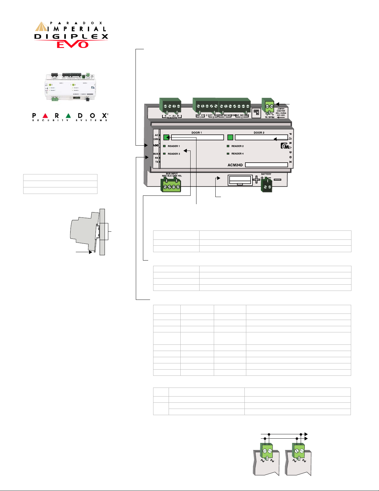
The ACM24D Access Control Module can
control two doors and can support REX devices,
readers, locking devices and door contacts.
Door contacts that are connected to the
ACM24D are programmed using BabyWare
software and can be assigned to zones in the
Imperial system.
Installation
The ACM24D is a
standard 35mm
DIN rail module.
Using the
supplied DIN rail,
the ACM24D can
be mounted in any
location.
Alternatively, it
can be mounted in
a standard DIN rail enclosure. To attach the
module, align the top of the DIN rail as shown in
Figure 1 and apply pressure to the module until it
clicks into place. To remove the ACM24D from a
DIN rail, pull the release clip and remove the
module.
To facilitate installation and servicing, the
ACM24D terminals can be detached from the
module. Wires can be labeled using the supplied
tie wraps.
Door contacts connected to the system follow
the control panel’s EOL definition. When EOL is
enabled and door contacts are not used, place a
1k
Ω resistor across the CT and C input terminals.
If EOL is disabled, use a jumper. If the REX
device is not used, place a jumper across the
RX
and C terminals.
Stand-Alone Mode
The ACM24D stores all access codes and cards
in memory. If panel communication is lost, the
ACM24D will continue to function normally.
Events will be stored in memory. When
communication is restored, events are
automatically uploaded to the panel.
Upgrading the Firmware
Imperial
The firmware of the ACM24D can be in-field
upgraded through the V32’s RS485 ACCESS
port using BabyWare.
EVO/DGP
The ACM24D firmware can be upgraded through
WinLoad using the CV4USB RS-485/RS-232
Converter. Refer to the firmware upgrade
instructions found at: paradox.com - Software WinLoad - Firmware Upgrade Instructions.
Imperial V32
EVO48, EVO192
DGP-848, DGP-NE96, EVO96
Figure 1: DIN Rail Mounting
Release
clip
35mm
DIN rail
Communication LED Feedback
Bus RX TX Condition
off green - flash green - flash OK (panel communication in progress)
off off off OK (no data RX/TX)
red off off Short on GRN or YEL
red off green
Communication failure / Too many modules on
Multibus
red green green Multibus lines reversed (Green / Yellow)
red flash off off Bus power too low
red flash green - flash green - flash Locate mode
blue --- --- Communication with V32 panel / Multibus mode
blue flash off off Firmware upgrade in progress
Power LED Feedback
LED Colour Condition
AC green AC or DC power is supplied
CHRG
green Battery is low / charging
green (less than 4 sec.) Battery test
Door LED Feedback
DOOR1 and DOOR2 manual control buttons display door status and can override door
programming. Manually unlocked doors remain unlocked for the minimum period
programmed in BabyWare.
Colour Condition
green on Door unlocked
red on Door locked
Door Labels
Space is provided to label
each door.
Fuse - not used
Detachable Terminals
Pry with screwdriver if
necessary.
Locate Mode
• For Imperial panels, a Module Locate can be started or stopped using BabyWare software
or by pushing the module’s LOC button. When a Module Locate is initiated, a flashing
occurs of the module’s LEDs (BUS RX and TX flash at 1Hz) as well as the module’s
representation in BabyWare.
• For DGP/EVO panels, a Module Locate can be initiated using section [4002] (EVO) or
[952] (DGP-48 / DGP-848). To end a Module Locate, press the LOC button.
Reader LED Feedback
red flash Reader auxiliary power failure
red on Reader is missing
green on Readers OK
off No reader programmed for this door
Transformer Sharing
Modules can share a central AC
transformer (16 to 24V
AC) throughout the
system. Ensure that the total power output
of the transformer is respected.
.
16 / 24 Vac 16 / 24 Vac
ACM24DACM24D
Connect to other
modules
compatible with
transformer
sharing.
Transformer
EVO / DGP Programming
When used on an EVO/DGP system, the ACM24 appears in WinLoad as two ACM12 modules.
Serial Numbers
Example: ACM24D = 3500556A ACM12 #1 = 3500556A
ACM12 #2 = 3500556B (plus 1 number / letter)
Page 2
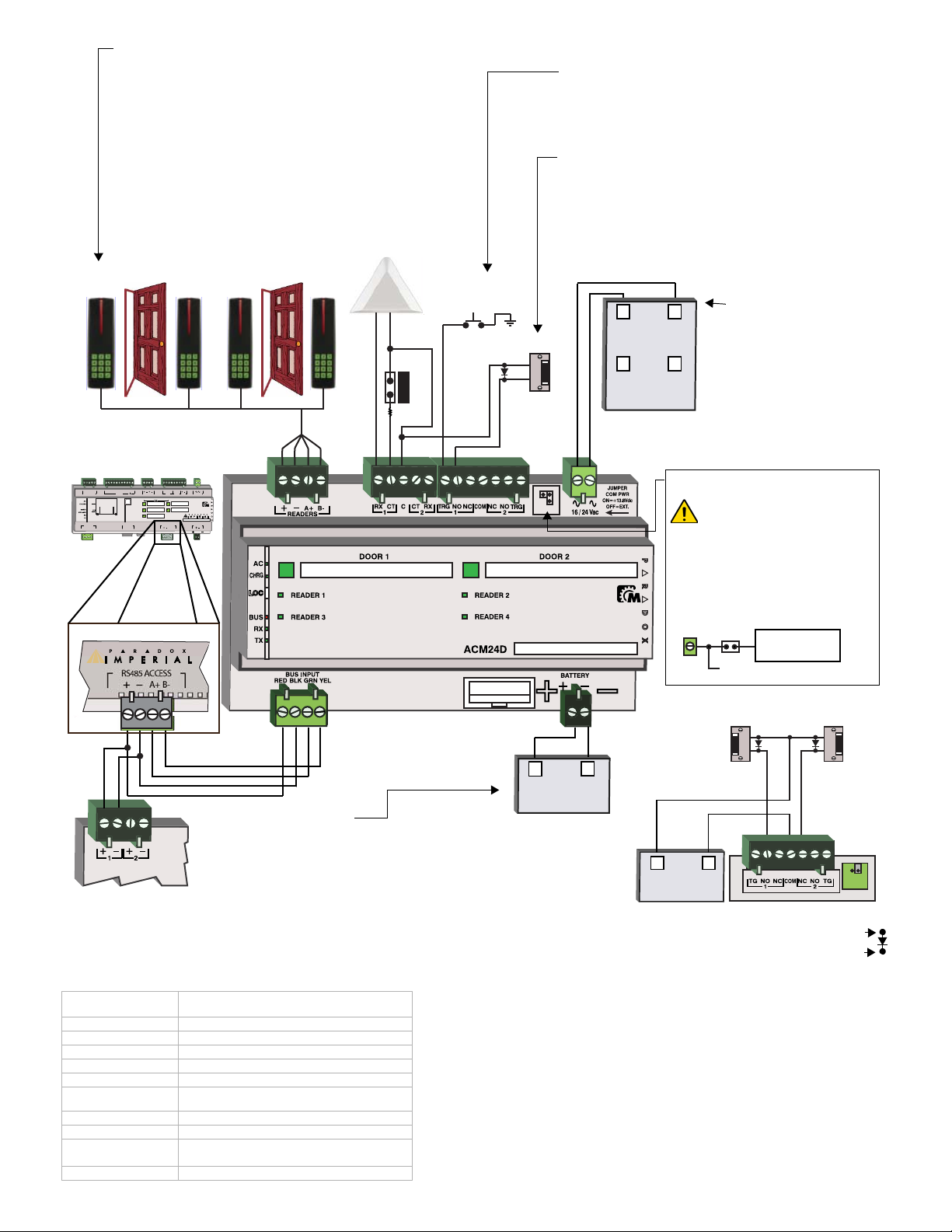
12Vdc
Battery
+
-
Door 2Door 1
1234
REX Devices
Contact
1 kΩ**
Optional
external trigger
Fail secure
latch (N.O.)
*
+
-
16 - 36Vdc
Power supply
~ ~
16 - 24Vac
Power supply
or
PS27D Power supply
Internal Power
Supply
Jumper
To COM of relays
COM
GR1T1RGTP C1 23 4C 56 7 8
2-WIRE
SMOKE
C1234
COM NC NO
BELL
A+B-
RED GRNBLK YEL
BATTERY TBL
ETHERNET
10/100 Mbps
BATTERY
USB POWER
16 / 24 Vac
ETHERNET
PHONE LINE
MULTIBUS
RS485 ACCESS
ZONES 13.8 Vdc AUX
700 mA MAX.
PGM 55APGM
100mA
V32
USB 2.0
PORT
USB RX/TX
RS485 RX/TX
BELL
Input Power
Use a 16-24VAC (50/60 Hz)
transformer with minimum
75VA. as shown in the
connection diagram. Do not
use switch-controlled outlets
to power the transformer. It
is possible for modules to
share a central
AC supply
(16 to 24 V
AC) throughout
the system.
Backup Battery
To power the module’s door lock relay during a power failure, connect a
12Vdc (minimum capacity of 7Ah) rechargeable acid/lead or gel cell
backup battery as shown in the connection diagram. Apply AC power
before connecting the battery.
Use supplied cable. If using custom wiring, add a fuse near the battery.
Battery charge current: 350mA/500mA (configurable in BabyWare).
Jumper Settings (J2)
When the J2 jumper is ON, internal
power is fed to
COM of both relays (up
to 2A at 12V). If using external power,
remove the J2 jumper and supply
power to the
COM input (see below).
Remove J2 jumper before
supplying external power.
Readers
Each ACM24D on a V32 can be assigned with up to 4 readers / 2
per door (EVO/DGP - 2 readers / 1 per door). The ACM24D
supports R910 (V2.0 or higher) and/or R915 (any version) 4-wire
card readers (up to 500mA). Readers 3 and 4 are optional and
can be used as passback or SAS readers (one man trap, two-door
access).
Readers are assigned to the ACM24D in BabyWare (Imperial) or
WinLoad/keypad assignment (EVO/DGP).
Reader LED
Orange slow flash = reader start up / too many readers on module
Orange fast flash = reader not assigned
Red on = reader is assigned to a door
* 1N4007 Diode
Connect the cathode to + voltage
Connect anode to - voltage
Do not use a diode with AC power
** Follows control panels EOL definition
Anode
Cathode
Connecting an External Trigger
The external negative trigger can also be activated using a
push button. When the push button is pressed, the door will
unlock. The PGM or push button must ground the negative
trigger.
Energy Saving Feature
When door locks are activated, voltage increases*. When
the activation period expires*, the ACM24D will go into
power saving mode and voltage will be reduced*.
This feature is only available when using internal power (J2
on).
* These settings are configurable with BabyWare software.
External Power
Technical Specifications
Power Input Voltage:
16-24Vac / 16-36Vdc
Transformer Sharing compatible
Power Input Rating: 75VA / 50W
Current Consumption: min. 127mA max. 183mA
Aux. Readers: 12Vdc, 500mA max.
Aux. Locks: 6-12Vdc, 3.1A (internal)
Battery: 12Vdc, 7Ah
No. of Outputs:
2 x form C relay rated at 3.5A per door / 28Vdc,
N.O. / N.C.
No. of Zones: 4 (Door Contact & REX device - 2 per door)
No. of Inputs: 2 (Negative Trigger - 1 per door)
Operating
temperature:
0ºC to 50ºC (32ºF to 122ºF)
Software: BabyWare, WinLoad V4.6
Warranty
For complete warranty information on this product please refer to the Limited Warranty Statement found
on the website www.paradox.com/terms. Y our use of the Paradox product signifies your acceptance of all
warranty terms and conditions.
Paradox Imperial, Mama, Paradox Mama and BabyWare are trademarks or registered trademarks of
Paradox Security Systems Ltd. or its affiliates in Canada, the United States and/or other countries. Mark
X is a registered trademark of Koninklijke Philips Electronics N.V For the latest information on products
approvals, such as UL and CE, please visit www.paradox.com.
© 2008 Paradox Security Systems Ltd. All rights reserved. Specifications may change without prior notice.
One or more of the following US patents may apply: 7046142, 6215399, 6111256, 6104319, 5920259,
5886632, 5721542, 5287111, 5119069, 5077549 and RE39406 and other pending patents may apply.
Canadian and international patents may also apply .
V32 control panel
(RS485 ACCESS)
Power Supply
The V32’s RS485 bus must
be supplied with 12Vdc
power.
TM
~ ~
24Vac
24
Vac
Latch
**
Power supply
24
Vac
Latch
J2 OFF =
External
power
J2
 Loading...