

Page 1
Installation Guide
Connect70
Paradigm
Page 2
- 2 -
Paradigm
The information in this document has been carefully compiled and checked for technical
accuracy. Paradigm Communication Systems Ltd. accept no liability for inaccuracies or errors. In
line with the company policy of technical advancement, the information within this document may
be changed. The user should ensure that the correct issue of the document is used.
Paradigm assumes no responsibility for the use of this document if any unauthorised changes to
the content or format are made.
This document is provided without implied or expressed warranty of any kind, including but not
limited to the implied warranties of merchantability and tness for purpose.
Other manufacturers’ registered trademarks and trade names which appear in this document are
hereby acknowledged.
Comments or correspondence regarding this document should be addressed to:
Paradigm Communication Systems Limited
Paradigm House
14 Wilsom Road
Alton, Hampshire
GU34 2PP
England
Tel: +44 (0) 1420 88199
Fax: +44 (0) 1420 88842
Email: support@paracomm.co.uk
© Paradigm Communication Systems Limited 2015. All rights reserved.
No part of this document may be reproduced in any form without the prior written consent of
Paradigm Communication Systems Limited. Use of the information contained herein is strictly
reserved for Paradigm Communication Systems Limited. Other use in any form and/or by any
means whatsoever is strictly prohibited.
DN: ED-IMA-02396
Rev: 04
Release Date: 23/07/2015
Legal
Safe Use
WARNING
Radiation Hazard. Transmitter power levels are sufcient to cause blindness or other serious
injury to body tissue. Do not power on the PIM and Transceiver until it is safe to do so.
WARNING
Risk of Electric Shock. High voltages exist within the units and the cables providing power to
the units. Always remove power from these devices when performing maintenance. Do not
modify power cables or physical unit in any way.
The equipment described in this manual is intended to be installed, used and operated only
for the purpose for which it was designed, in accordance with the safety procedures and any
other instructions given in this manual. Nothing stated in this manual reduces the professional
responsibilities of users for the exercise of sound judgement and best practice.
WARNING
This equipment is intended for installation in a restricted access location. The equipment
should not be touched during operation.
Page 3

- 3 -
Installation Guide
Connect70
Contents
Safe Use ............................................................................................................2
Legal ..................................................................................................................2
Contents ............................................................................................................3
Site Survey for Antenna Installation ...............................................................4
Installation Process..........................................................................................4
Antenna Packaging Content ............................................................................5
Recommended Tools for Installation ..............................................................5
Skew adjustment ............................................................................................6
Attach the Az/El mount ...................................................................................7
Attach Antenna dish to Az/El mount ...............................................................8
Attach Boom to Az/El mount ..........................................................................9
Mounting the Transceiver .............................................................................10
RF Circuit Setup .............................................................................................11
Antenna Adjustment ......................................................................................12
Skew Adjustment ..........................................................................................12
Elevation Adjustment ....................................................................................12
Azimuth Adjustment .....................................................................................13
Antenna Grounding ........................................................................................14
Skew Calculation Chart..................................................................................15
Elevation Calculation Chart ...........................................................................16
Azimuth Calculation Chart .............................................................................17
Transceiver Control LEDs..............................................................................18
Transceiver Port Identication ......................................................................18
Pointing with Skew .........................................................................................19
Periodic Maintenance.....................................................................................19
Page 4
- 4 -
Paradigm
All equipment necessary for the assembly of this Antenna Terminal is included. To complete the
pointing process, a portable computer may be necessary.
Installation
Process
Investigate the intended installation site for the satellite antenna, and using the azimuth and
elevation angles provided by the PIM (see PIM Operators Manual), conrm there are no line-
of-sight obstructions. Remove any obstructions if possible, or select a new location with a clear
line-of-sight to the satellite.
Site Survey
for Antenna
Installation
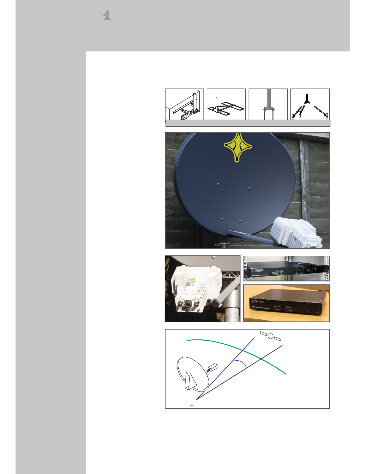
1. Install the Antenna mount
• Wall Mount
• Non-Penetrating
Roof Mount
• Kingpost
• Tripod
2. Assemble and Install the
Antenna
4. Point the antenna
• Coarse Pointing
• Fine Pointing
5. Commission the
installation
3. Assemble RF Circuit
• Transceiver
• PIM
Refer to the ParadigmGX Antenna Mount Installation Manual
Page 5

- 5 -
Installation Guide
Connect70
Package Contents:
1. 69cm 1-piece pressed-steel antenna
2. Az/El mount
3. Antenna Rear Bracket
4. Skew Plate
5. Boom Arms
6. 5W Ka-Band transceiver with integrated feed
7. Transceiver Mounting Bracket
8. IFL Cable (M&C, Tx, Rx), optional Paradigm-GPS
9. PIM (Outdoor, Indoor, or Rack Mount)
10. Assembly nuts, bolts and washers
11. Tool Kit, Tie-wraps, Compass, Amalgamating tape
1
2
3
4
Antenna
Packaging
Content
5
6
7
Compass & Inclinometer
Spirit level
Torque wrench
Spectrum Analyser
Portable Computer to complete the pointing process
Recommended
Tools for
Installation
Page 6

- 6 -
Paradigm
Skew
adjustment
Referring to the skew angle calculator on page 15 and the skew adjustment process on
page 12, set the skew angle for the satellite antenna. Rotate the antenna rear bracket to the
calculated skew angle, and tighten the M8 nylon insert hex nuts using the 1/2” ring spanner. Set
the Az/El mount elevation to the approximate elevation of the satellite.
Page 7

- 7 -
Installation Guide
Connect70
Attach the Az/El
mount
Attach the Az/El mount to the antenna mount post. Do not secure the clamp at this time, but
allow the antenna free movement through azimuth.
Referring to the skew angle calculator on page 15 and the elevation adjustment process on
page 12, set the coarse elevation for the satellite antenna.
Referring to the azimuth adjustment process on page 13, set the coarse azimuth.
Page 8

- 8 -
Paradigm
Attach Antenna
dish to Az/El
mount
Attach the antenna reector to the Az/El mount by locating the 4 M8x20mm bolts and M8 nylon
insert hex nuts and secure using the 13mm ring spanner.
Page 9

- 9 -
Installation Guide
Connect70
Attach Boom to
Az/El mount
Slide the boom through the antenna reector into the bracket base. Secure the boom using 5/16”
x 3/4” hex bolts, an 8.4mm at washer and an 8.4mm spring washer. Secure rmly into place by
tightening each bolt using the 13mm ring spanner.
Page 10

- 10 -
Paradigm
Mounting the
Transceiver
Attach the transceiver to the transceiver mounting bracket using the using 4 x M6x18mm hexsocket bolts. Tighten using the 5mm hex key.
Attach the transceiver mounting bracket to the boom using 5/16” x 3/4” hex bolts, an 8.4mm at
washer and an 8.4mm spring washer. Secure rmly into place by tightening each bolt using the
13mm ring spanner.
Page 11

- 11 -
Installation Guide
Connect70
Pointing
Setup:
IF-L (Tx)
Transceiver /
BUC Control/
Power
RF Circuit
Setup
Transceiver / BUC
PIM
IF-L (Rx)
Frequencies:
GSC: 19707 Mhz**
IF: 1457 Mhz
RF Splitter
with DC
block
Spectrum Analyser
IF: 1457 MHz
Span: 500khz
Expected SNR: 9-13dB*
Transceiver
Rx
PIM
Rx
* - dependant on footprint location, weather conditions and look angle. SNR can read above 13dB.
** - Conrm with your service provider.
Page 12

- 12 -
Paradigm
Antenna
Adjustment
Loosen the 5 nuts on the rear of the skew adjustment plate, and rotate the antenna to the
required skew angle. Refer to page 15 to calculate skew angle for pointing the antenna.
Elevation
Adjustment
Loosen the elevation clamping bolts. Adjust the elevation as required by rotating the elevation
adjustment handle. Coarse and Fine adjustment is be achieved using the same method. After
achieving the desired elevation, tighten the clamping bolts to prevent movement. Refer to page
16 to calculate elevation angle for pointing the antenna.
Skew
Adjustment
Page 13

- 13 -
Installation Guide
Connect70
Coarse azimuth adjustment is performed by rotating the antenna on the mounting pole, and
tightening the 3 vertically aligned clamping bolts when a satisfactory coarse azimuth is achieved.
For ne azimuth adjustment, slightly loosen off the 3 x M8 nuts (A) located on the underside of
the Az/El Mount Assembly. Adjust the ne azimuth by turning the plasti-bolt (B) until the desired
angle is achieved. After achieving the desired azimuth, tighten the three base plate nuts (A).
Refer to page 17 to calculate azimuth angle for pointing the antenna.
Azimuth
Adjustment
A
B
Page 14

- 14 -
Paradigm
NON-PENETRATING ROOF MOUNT
Ground wire
with ring
Ground
Lug
5mm self-tapping
screw
Too t h
Washer
M6 x 16 mm
Self Tapping
Screw
Ground
Lug
Ground Wire
with Ring
Too t h
Washer
Note: Grounding wire and hardware are not
supplied for pole mount, or non penetrating roof
mount. Installation mount and associated hardware
are not supplied.
Ground Wire
Secure
Clamp
Grounding Rod
Ground Wire
Ground
Block
Coaxial Cables ( To
Transceiver)
Coaxial
Cables
(From PIM)
Note: Ground wire, secure
clamp, grounding rod, coaxial
cables and ground block are not
supplied.
IMPORTANT: All antenna systems must
be properly grounded. Typical grounding
methods are shown as examples. Tighten all
hardware securely to assure good continuity.
TO GROUNDING
ROD
WALL MOUNT
Too t h
Washer
Ground Wire
with Ring
Ground
Lug
M6
Lock
Nut
M6 x 16mm
Hex Head
Screw
TO GROUNDING
ROD
Antenna
Grounding
POLE MOUNT
Page 15

- 15 -
Installation Guide
Connect70
Skew
Calculation
Chart
Feed
Earth station latitude in degrees, north or south of the equator.
To calculate the required skew angle of the satellite terminal:
1. Conrm the current earth station latitude in degrees on the horizontal axis.
2. Conrm the correct curve for the delta (Δ) in degrees between the earth station longitude
and the satellite longitude.
3. Read off the vertical axis for the skew angle.
Example:
Earth station location: 001° 02’ 49” W 51° 09’ 02” N (51.151°, -001.047°)
Satellite Location: 62.6° E
Longitude Delta: (-001.047 - 62.6) = -63.55°
Skew angle: -35.5°
Skew Angle
Polarisation Chart Sign
Values (+ or -)
Northern
Hemisphere
Southern
Hemisphere
Antenna Site West of Satellite
Longitude
- +
Antenna Site East of Satellite
Longitude
+ -
FEED ROTATION
(Facing Antenna)
For + Polarisation Rotate Counter Clockwise
For - Polarisation, Rotate Clockwise
Page 16

- 16 -
Paradigm
To calculate the elevation that would incorporate the skew angle of the satellite terminal:
1. Conrm the correct curve for the longitude delta (Δ) calculated for the Skew Calculation.
2. Find latitude on the horizontal axis.
3. Find where the curve for the calculated delta intersects the latitude value.
4. Read off the vertical axis for the elevation angle.
Example:
Earth station location: 001° 02’ 49” W 51° 09’ 02” N (51.151°, -001.047°)
Satellite Location: 62.6° E
Longitude Delta: (-001.047 - 62.6) = -63.55°
Elevation angle: 7.7°
Elevation
Calculation
Chart
Earth station latitude in degrees, north or south of the equator.
Elevation
Page 17

- 17 -
Installation Guide
Connect70
Azimuth
Calculation
Chart
To calculate the azimuth that would incorporate the skew angle of the satellite terminal:
1. Conrm the correct curve for the delta (Δ) calculated for the Skew Calculation.
2. Find latitude on the horizontal axis.
3. Find where the curve for the calculated delta intersects the latitude value.
4. Read off the vertical axis for the azimuth angle.
Example:
Earth station location: 001° 02’ 49” W 51° 09’ 02” N (51.151°, -001.047°)
Satellite Location: 62.6° E
Longitude Delta: (-001.047 - 62.6) = -63.55°
Azimuth angle: 111°
AZIMUTH COLUMN READING WHEN EARTH STATION IS WEST OF SATELLITE
AZIMUTH COLUMN READING WHEN EARTH STATION IS EAST OF SATELLITE
EARTH STATION ANTENNA LATITUDE IN DEGREES NORTH OR SOUTH OF EQUATOR
Page 18

- 18 -
Paradigm
1. Transmit (Tx) IFL (N-Type)
2. Control/Power
3. Receive (Rx) IFL (N-Type)
4. Monitor Port (F-Type)
1
4
3
2
Transceiver Port
Identication
1
43
2
Transceiver
Control LEDs
1. Power:
a. Green: Power On, Rx and Tx PLL Locked
b. Red: Power On, IF Overdrive Condition
c. Red (Blinking): Power On, Rx and/or Tx PLL unlocked
2. Polarity:
a. Red: Tx = LHCP (Connect Series Antennas)
b. Green: Tx = RHCP (Connect Series Antennas)
3 & 4. Frequency Band
3 = Green, 4 = Green: Low Band Tx.
3 = Green, 4 = Red: High Band Tx.
LED 4 Colour will cycle during One Touch Commissioning (see
PIM Operators Manual)
Page 19

- 19 -
Installation Guide
Connect70
To ensure peak performance of the antenna system and to maintain validity of the warranty, the
user should perform a periodic inspection every 6 months or following any severe weather event.
At a minimum the following items should be inspected.
1. INSTALLATION MOUNT
• Check for loose hardware - tighten if necessary.
• Check integrity of anchor bolts or hardware securing mount to the building or
foundations.
• Check ballast of Non-Penetrating Roof Mounts - cracked or broken blocks must be
replaced.
• Check hardware and structural members for signs of corrosion - repair or replace as
needed.
2. ANTENNA BACK STRUCTURE OR AZ/EL MOUNT
• Check for loose hardware - tighten if necessary.
• Check for signs of structural damage such as bending or cracking.
• Check hardware and structural members for signs of corrosion - repair or replace as
needed.
3. REFLECTOR
• Check integrity of bolts securing reector to back structure or Az/El mount. Tighten any
loose hardware.
• Check for signs of damage such as cracking. Inspect reector face for impact damage.
• Check hardware for signs of corrosion - repair or replace as needed.
4. FEED SUPPORT STRUCTURE
• Check for loose hardware - tighten if necessary.
• Check for signs of structural damage such as bending.
• Check hardware and structural members for signs of corrosion - repair or replace as
needed.
5. FEED & RF COMPONENTS
• Check for loose hardware - tighten if necessary.
• Check hardware for signs of corrosion - repair or replace as needed.
• Check feed lens or window for damage or signs of leaking.
• Check waveguide ange connections between feed and RF electronics.
6. ELECTRICAL
• Check for loose cables and connectors - tighten if necessary.
• Check for tight grounding connections.
• Check cables for weathering or cracks.
Periodic
Maintenance
Pointing with
Skew
Pointing an antenna that has no skew adjustment requires moving the antenna once through
azimuth, centring on the peak, and moving the antenna once through elevation and centring
on the peak. Pointing an antenna that has skew adjustment applied will require an iterative
approach to passing through the elevation at different azimuth values, and calculating the
azimuth value where the elevation signal was strongest.
1. Azimuth sweep locates signal peak.
2. At azimuth peak, elevation sweep
locates signal peak.
1. Azimuth sweep locates signal peak.
2. At azimuth peak, elevation sweep
misses signal peak.
3. Iterative azimuth/elevation sweeps
are required.
No Skew With Skew
Page 20

Paradigm Communication Systems Ltd.
Paradigm House, 14 Wilsom Road
Alton, Hampshire, UK
GU34 2PP
+44 (0)1420 88199
sales@paracomm.co.uk
 Loading...