

Page 1
100 LEG PRESS
WARNING:
Read and follow all directions
for each step to insure proper
assembly of this product.
ASSEMBLY INSTRUCTIONS
CLASS H
PART# 7155801
REV . B
1
Version: 100102
Revision: 09/26/01
Page 2
IMPORTANT NOTES
Please note:
* Thank you for purchasing the Parabody 100102 LEG PRESS. Please read these instructions
thoroughly and keep them for future reference. This product must be assembled on a flat,
level surface to assure its proper function.
We recommend cleaning your product (pads and frame) on a regular basis, using warm soapy
water. Touch-up paint can be purchased from your Parabody customer service representative
at (800) 328-9714.
There is a risk assumed by individuals who use this type of equipment. To minimize risk, please
follow these rules:
1. Inspect equipment daily . T ighten all loose connections and replace worn parts immediately.
Failure to do so may result in serious injury.
2. Do not allow minors or children to play on or around this equipment.
3. Exercise with care to avoid injury .
4. If unsure of proper use of equipment, call your local Parabody distributor or call the
Parabody customer service department at (800) 328-9714.
5. Consult a physician before beginning any exercise program.
T ools Required for Assembly
* 3/4” wrench
* 9/16” wrench
* Ratchet with 3/4” and 9/16” sockets
* Adjustable wrench
* T ape measure
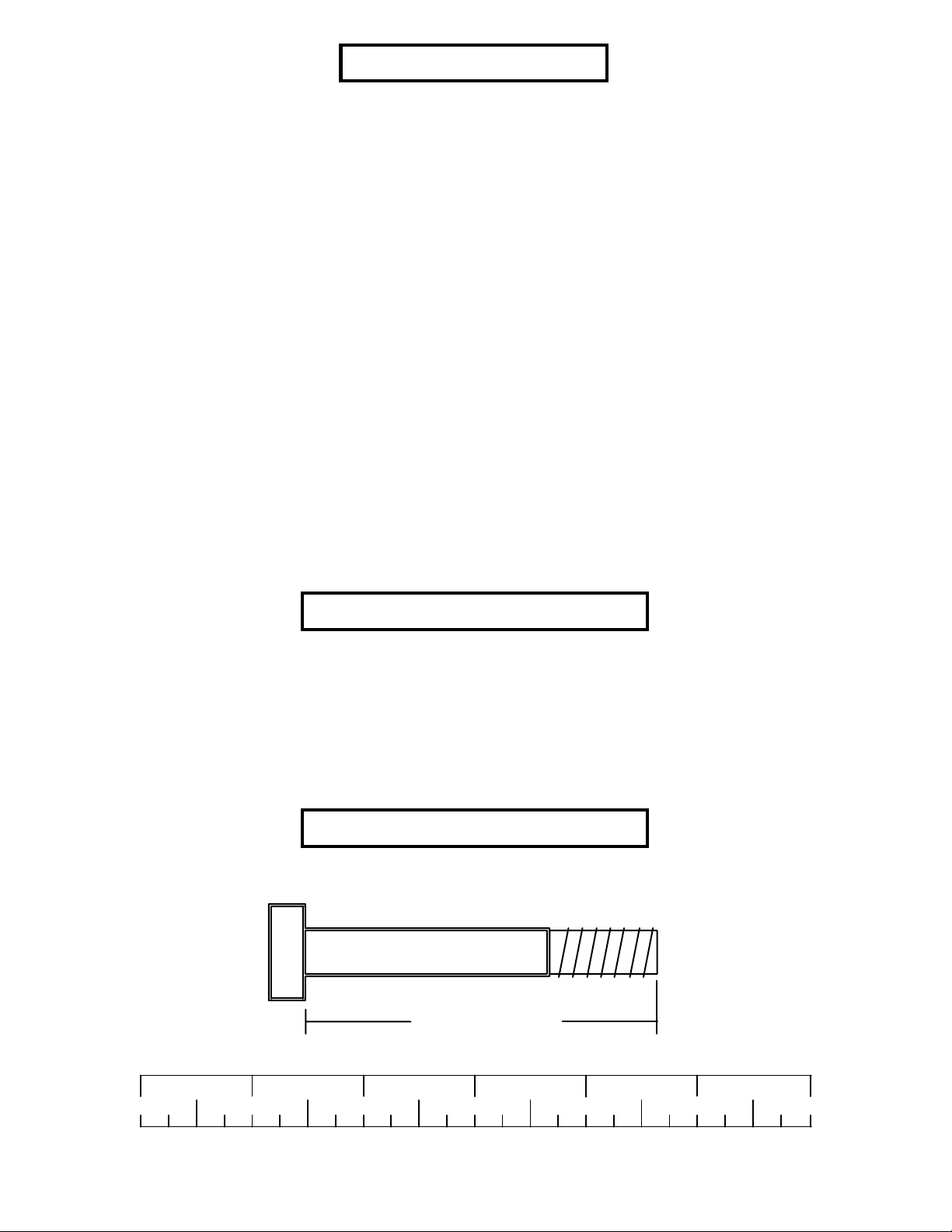
Bolt Length Ruler
NOTE: BOL T LENGTH IS MEASURED FROM THE UNDERSIDE OF THE HEAD OF THE BOLT.
BOL T LENGTH RULER:
1/2 1/2 1/2 1/2 1/2 1/2
0
1
BOLT LENGTH
2
345
2
6
Page 3
PARTS LIST
KEY
1
2
3
4
5
6
7
8
9
PART #
7140508
7140802
6806208
7140608
7140708
7140908
7128108
6994721
3102922
DESCRIPTION
FRAME
SEA T ADJUST
HANDLE
MAIN ARM
SECOND ARM
FOOTPLATE
PULLEY BRACKET
PAD
3/8 X 2-3/4” BOLT
QTY
1
1
1
1
1
1
1
2
6
KEY
10
11
12
13
14
15
16
17
18
PART #
3102501
3102802
3102944
3102801
3104901
6416601
7115201
7128201
6140701
DESCRIPTION
3/8” FLA T W ASHER
3/8” LOCK NUT
1/2 X 5” BOLT
1/2” LOCK NUT
3/4” FLANGE BEARING
P ARAGLIDE (QTY 8)
SPRING PIN
3/4 X 4” SHAFT
1” SQ. GLIDE
QTY
8
2
4
4
8
1
1
4
2
3
Page 4
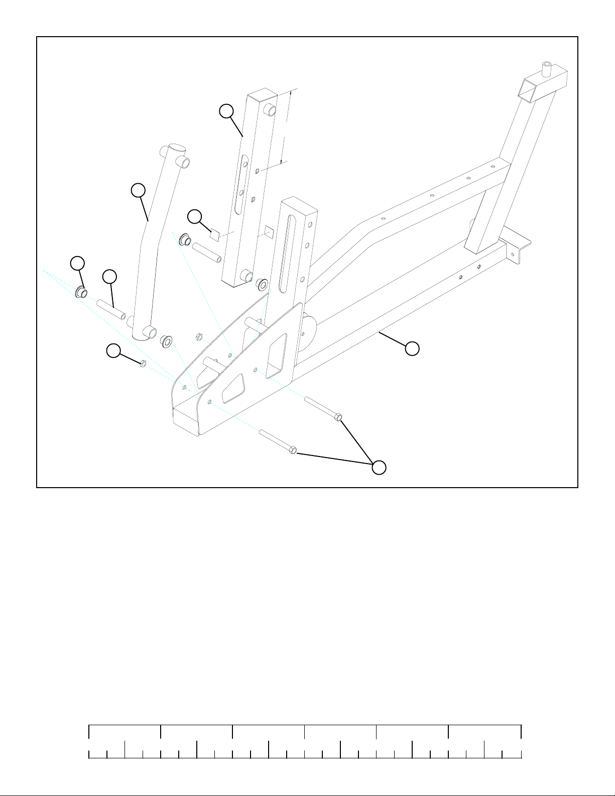
For assembly to the the 220 and 880 Gym Systems .
4
5
18
14
17
Make sure MAIN ARM
9-1/2"
is orientated correctly
13
12 1/2 X 5”
1
FIGURE 1
STEP 1:
• NOTE: Follow STEP 1 for the assembly of the LEG PRESS to the 220 and 880 Gym Systems. If you have the 777 Gym
System proceed to STEP 2.
• SECURELY assemble the SECOND ARM (5) to the FRAME (1) using one 1/2 X 5” BOLT (12), two 3/4” FLANGE BEARINGS
(14), one 3/4 X 4” SHAFT (17) and one 1/2” LOCK NUT (13). See FIGURE 1.
• SECURELY assemble the MAIN ARM (4) to the FRAME (1) using one 1/2 X 5” BOLT (12), two 3/4” FLANGE BEARINGS (14),
one 3/4 X 4” SHAFT (17) and one 1/2” LOCK NUT (13). See FIGURE 1. (NOTE: Make sure MAIN ARM is orientated cor-
rectly, top hole should be 9-1/2” from the top of arm as shown in FIGURE 1.)
• SECURELY assemble two 1” SQ. GLIDES (18) to each side of the MAIN ARM (4) where the MAIN ARM (4) contacts the FRAME
(1) See FIGURE 1.
• Proceed to to STEP 3.
1/2 1/2 1/2 1/2 1/2 1/2
0
1
2
345
4
6
Page 5

For assembly to the the 777 Gym System .
4
5
18
14
17
11-1/4"
Make sure MAIN ARM
is orientated correctly
1
FIGURE 2
13
12 1/2 X 5”
STEP 2:
• NOTE: Follow STEP 2 for the assembly of the LEG PRESS to the 777 Gym System. If you have the 220 or 880 Gym Systems
proceed to STEP 3.
• SECURELY assemble the SECOND ARM (5) to the FRAME (1) using one 1/2 X 5” BOLT (12), two 3/4” FLANGE BEARINGS
(14), one 3/4 X 4” SHAFT (17) and one 1/2” LOCK NUT (13). See FIGURE 2.
• SECURELY assemble the MAIN ARM (4) to the FRAME (1) using one 1/2 X 5” BOLT (12), two 3/4” FLANGE BEARINGS (14),
one 3/4 X 4” SHAFT (17) and one 1/2” LOCK NUT (13). See FIGURE 2. (NOTE: Make sure MAIN ARM is orientated cor-
rectly, top hole should be 11-1/4” from the top of arm as shown in FIGURE 2.)
• SECURELY assemble two 1” SQ. GLIDES (18) to each side of the MAIN ARM (4) where the MAIN ARM (4) contacts the FRAME
(1) See FIGURE 2.
• Proceed to to STEP 3.
5
Page 6

14
17
4
5
FIGURE 3
STEP 3:
• Insert two 3/4” FLANGE BEARINGS (14) and one 3/4 X 4” SHAFT (17) into the SECOND ARM (5) as shown in FIGURE 3.
• Insert two 3/4” FLANGE BEARINGS (14) and one 3/4 X 4” SHAFT (17) into the MAIN ARM (4) as shown in FIGURE 3.
1/2 1/2 1/2 1/2 1/2 1/2
0
1
2
345
6
6
Page 7

13
6
5
4
12 1/2 X 5”
FIGURE 4
STEP 4:
• SECURELY assemble the FOOTPLATE (6) to the SECOND ARM (5) and the MAIN ARM (4) using two 1/2 X 5” BOLTS (12) and
two 1/2” LOCK NUTS (13). See FIGURE 4.
7
Page 8

1
3/8 X 2-3/4” 9
3
10
11
FIGURE 5
STEP 5:
• SECURELY assemble the HANDLE (3) to the FRAME (1) using two 3/8 X 2-3/4” BOLTS (9), four 3/8” FLAT WASHERS (10)
and two 3/8” LOCK NUTS (11) as shown in FIGURE 5.
1/2 1/2 1/2 1/2 1/2 1/2
0
1
2
345
8
6
Page 9

FIGURE 6
2
16
15
1
STEP 6:
• Attach eight PARAGLIDE STRIPS (15) to the inside of the tube on the FRAME (1) using the following steps:
• Thoroughly clean all surfaces where the PARAGLIDE STRIPS (15) are to be attached.
• Remove the PARAGLIDE STRIPS (15) from the paper backing and firmly apply them to all shown surfaces.
• SECUREL Y assemble one SPRING PIN (16) to the spring pin barrel on the FRAME (1) as shown in FIGURE 6.
• CAREFULLEY slide the SEAT ADJUST (2) into the FRAME (1) and engage the SPRING PIN into one of the adjustment holes.
See FIGURE 6.
9
Page 10

FIGURE 7
8
2
10
9 3/8 X 2-3/4”
STEP 7:
• SECURELY assemble one PAD (8) to the SEAT ADJUST (2) using two 3/8 X 2-3/4” BOLTS (9) and two 3/8” FLAT WASHERS
(10) as shown in FIGURE 7.
1/2 1/2 1/2 1/2 1/2 1/2
0
1
2
345
10
6
Page 11

3/8 X 2-3/4” 9
8
1
10
7
FIGURE 8
STEP 8:
• SECURELY assemble one PAD (8) to the FRAME (1) using two 3/8 X 2-3/4” BOLTS (9) and two 3/8” FLAT WASHERS (10) as
shown in FIGURE 8.
• Refer to the LEG PRESS ADAPTOR assembly instructions to attach the 100 LEG PRESS to the home gym. The PULLEY
BRACKET (7) will be attached at that time.
Thank you for purchasing the Parabody 100 LEG PRESS. If unsure of proper use of equipment, call your
local Parabody distributor or call the Parabody customer service department at (800) 328-9714.
11
 Loading...