

Page 1
Serious Steel
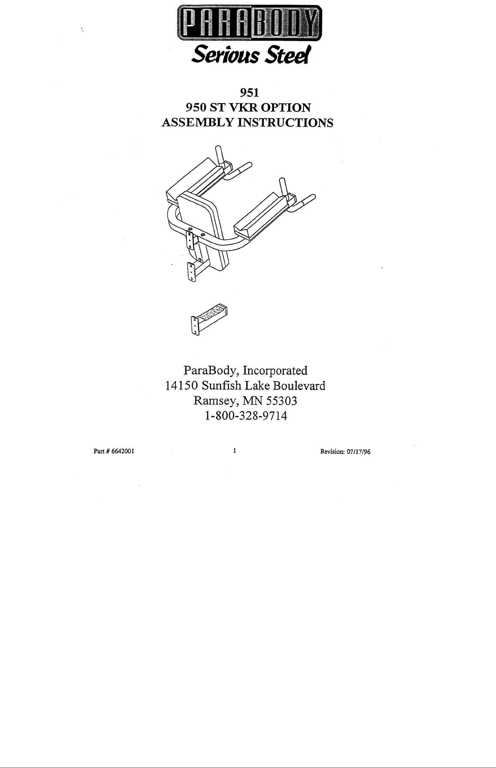
951
950 ST VKR OPTION
ASSEMBLY INSTRUCTIONS
Part # 6642001
ParaBody, Incorporated
14150 Sunfish Lake Boulevard
Ramsey, MN 55303
1-800-328-9714
1
Revision: 07/1"1/96
Page 2
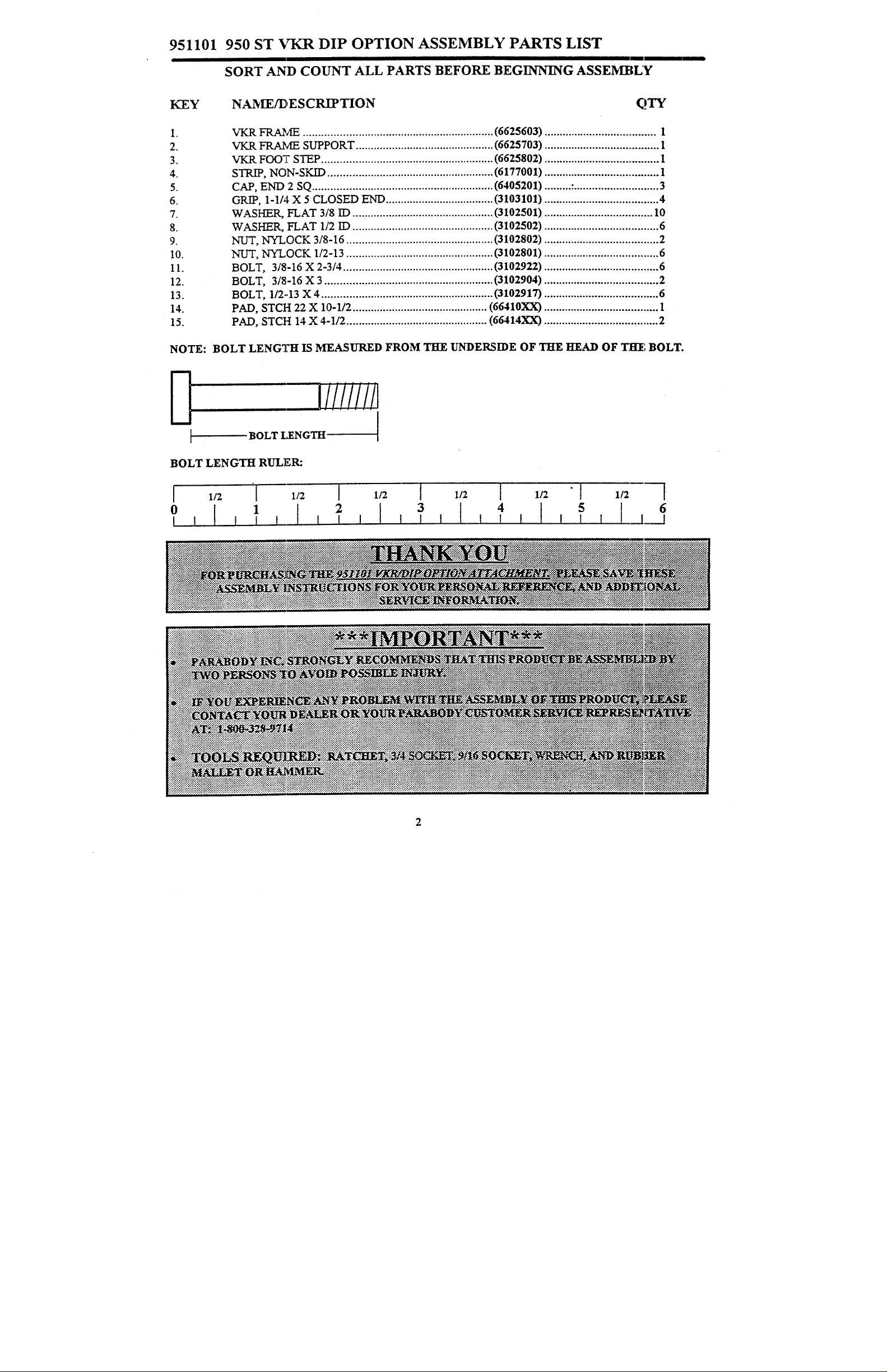
951101 950 ST VKR DIP OPTION ASSEMBLY PARTS LIST
SORT AND COUNT ALL PARTS BEFORE BEGINNING ASSEMBLY
KEY
2.
3.
4.
5.
6.
7.
8.
9.
10.
11.
12.
13.
14.
15.
NOTE: BOLT LENG’]?H IS MEASURED FROM THE UNDERSIDE OF THE HEAD OF THe’, BOLT.
NAS, TE/DESCRIPTION
VKR FRAME ...............................................................
VKR FRAME SUPPORT ..............................................
~ FOOT STEP .........................................................
STR~, NON-SKID .......................................................
CAP, END 2 SQ ............................................................
GRIP, 1-1/,I. X 5 CLOSED END ....................................
WASHER, FLAT 3/8 I:D ...............................................
WASKER, FLAT 1/2 ID ...............................................
NUT, NYLOCK 3/8-16 .................................................
NUT, NYLOCK 1/2-13 .................................................
BOLT, 3/8-16 X 2-3/4 ..................................................
BOLT, 3/8-16 X 3 ........................................................
BOLT, 1/2-.13 X 4 .........................................................
PAD, STCH 22 X 10-1/2 .............................................
PAD, STCH 14 X 4-1/2 ...............................................
(6625603) ...................................... 1
(6625703) ...................................... 1
(6625802) ...................................... 1
(6177001) ...................................... 1
(6405201) ......... .- ............................3
(3103101) ...................................... 4
(3102501) .................................... 10
(3102502) ...................................... 6
(3102802) ...................................... 2
(3102801) ...................................... 6
(3102922) ......................................
(3102904) ...................................... 2
(3102917) ...................................... 6
(66410XX) ...................................... 1
(66414XX) ......................................
6
2
I//!iiiil
BOLT LENGTH
BOLT LENGTH RULER:
0 1
2
3 ] 4 5
6
Page 3

VKR Uption Assembly Instructions
Use thls procedure to assemble the 951 VKR option to the ParaBody 950 ST.
Step 1
Insert two 2" sq. end caps (5) into the ends of the VKR frame (1) as shown on dr¢~wing.
A.
Insert one 2" sq. end cap (5) into the end of the VKR foot step (3) and apply one non-skid
B.
strip (4) as shown.
C. Slide four 1-1/4" grips (6) onto the handles of the VKR frame (1).
Step 2
Securely affoch two arm pods (15) fo the VKR frame (I) using four 3/8 x 2-3/4" bolls (11)
A.
four 3/8" washers (7).
Securely attach back pad (14) to the VKR frame support (2) using two 3/8 x 2-3/4!’ bolts
B.
and two 3/8" washers;
3
Page 4

Step 3
Loosely assemble the VKR frame support (2)
A.
the VKR frame (1) u:~ing two 3/8 x 3" bolts (12),
four 3/8" washers (7), and two 3/8" nylock nuts (9).
(Note: This connection will be secured in STEP 4-B.)
Step 4
Securely assemble the VKR frame (1) and the VKR frame support (2) fo the rear upright
A.
of the 950 ST GYM as shown using four 1/2 x 4" boils (13), four 1/2" washers
and four 1/2" nylock nuts
Securely tighten the VKR frame (1) and VKR frame support (2) connection.
B.
Securely attach the V’KR foot step (3) to the rear uprTghf of the 950 ST GYM as shown
C.
drawing, using two 1/2 x bolts (13), ~wo 1/2" washers (8), and two 1/2" nylock nuts (10).
4"
4
 Loading...