

Specifications and Main Features
- Model: ParaBody 950 ST
- Parts List: Contains 120 interchangeable parts like frame, pads, arms, weight stacks, and cables.
- Frame: Must be done over a leveled surfaced without any incline.
- Recommended Assembly: Two personnel suggested, in order to prevent tissue damage.
- Tools Required: Ratchet, 3/4 socket or wrench, 9/16 socket or wrench, 7/16 socket or wrench, adjustable wrench, 1/8 allen wrench, 5/32 allen wrench, 7/32 allen wrench, level, and rubber mallet or hammer.
- Weight Plates: Includes a total of 12, 5 pound weights.
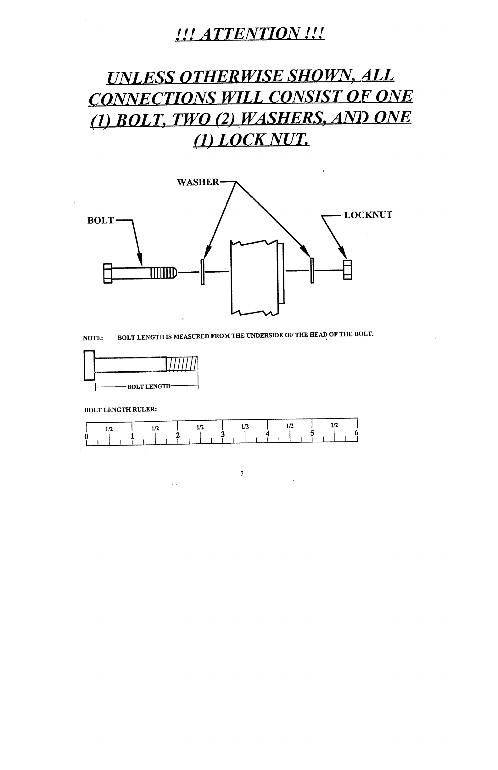
- Connection Type: Any assembled components have one bolt, two washers and one locknut for each connection.
Frequently Asked Questions
- Q: What is the weight capacity of the ParaBody 950 ST?
A: It is stated nowhere in the manual what the maximum user weight is.
- Q: Can the ParaBody 950 ST be assembled single handedly?
A: This type of assembly can be highly discouraged and never proceed with assembling the product alone.
- Q: How many sockets would be needed for the tool assembly?
A: Many tools would be required for assembly like, a ratchet, useful sockets, adjustable wrenches, allen wrenches, rubber mallet or hammer and plenty more.
- Q: Which sections does the ParaBody 950 ST comprise of as per the report?
A: the user manual contains functional components that total up to 120 parts.
- Q: Can one alter the weight stack? Is there a mention of it in the manual?
A: The manual does not describe however it is plausible to alter the weight. Remember Me: Features and Limitations.
User Manual
Page 1
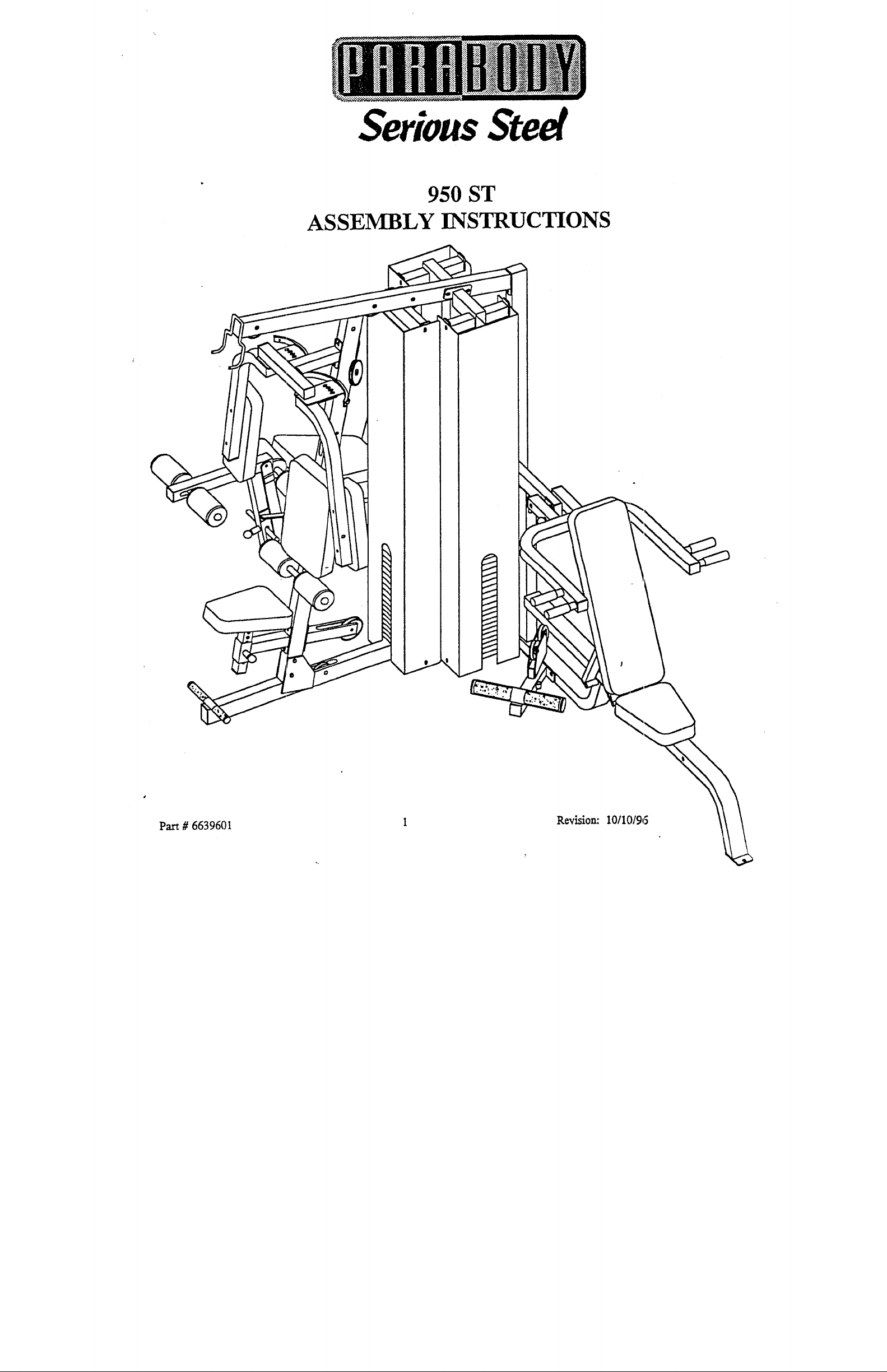
Serious Steel
950 ST
ASSEMBLY INSTRUCTIONS
Pa.rt # 6639601
R~vision: 10/10/96
Page 2

***IMPORTANT***
THE pARABODY 950 ST MUST BE ASSEMBLED ON A FLAT, LEVEL SURFACE TO ASSURE ITS PROPER
¯
FUNCTION.
PARABODY INC. STRONGLY RECOMMENDS THAT THIS PRODUCT BE ASSEMBLED B~( TWO PERSONS TO
AVOID" POSSIBLE INJURY.
¯
KEEP ALL FRAME CONNECTIONS LOOSE, UNTIL INSTRUCTED IN THE ASSEMBLY STEP SEQUENCES TO
SECURELY TIGHTEN. ~
¯
IF YOU EXPERIENCE ~IY PROBLEM WITH THE ASSEMBLY OF THIS PRODUCT, PLEASE CONTACT YOUR
DEALER OR YOUR PARABODY CUSTOMER SERVICE REPRESENTATIVE AT: 1-800-328-9’714
¯
TOOLS REQUIRED,: RATCHET, 3/4 SOCKET or WRENCH, 9/16 SOCKET or WRENCH, 7/16 SOCKET or
WRENCH, ADJUSTABI,E WRENCH, 1/8 ALLEN WRENCH, 5/32 ALLEN WRENCH, 7/32 ALLEN WRENCH, LEVEL,
and RUBBER MALLET or HAMMER
2
Page 3
IliA
TTENTION . !!
~
(1) B O L I; TWO (2) ~ WASHERS. AN_D__ONE
-- LOCKNUT
NOTE: BOLT LENGTH IS MEASURED FROM THE UNDERSIDE OF THE HEAD OF THE BOLT.
,1,3///ii!!1
BOLT LENGTH
BOLT LENGTH RULER:
1
2
3
4 [ I I I
Page 4
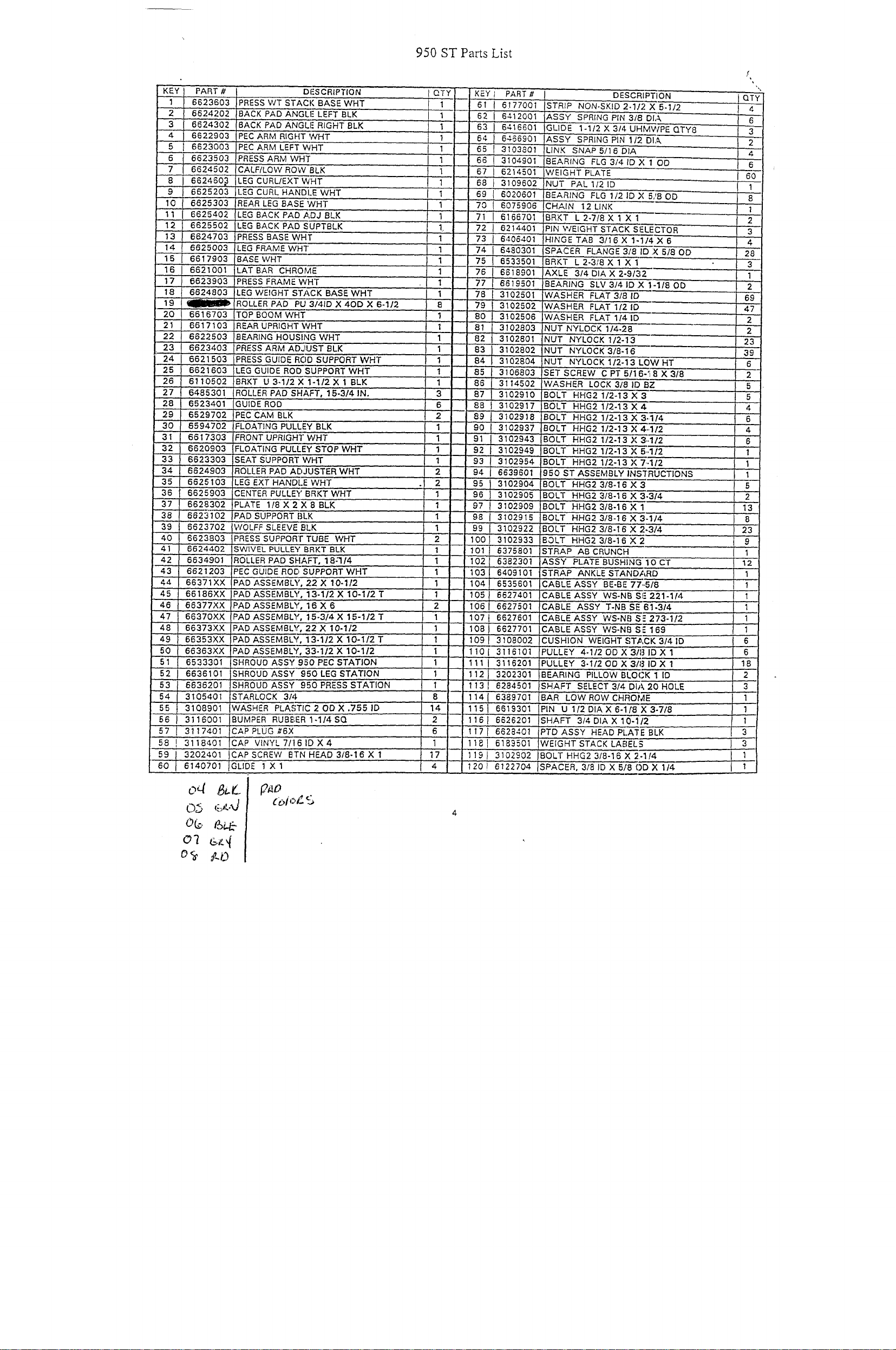
950 ST Pacts List
KEY} PART# DFSCRIPTION
II 6623603 PRESS WT STACK BASEWHT
2 I 6624202 BACK’ PAl) ANGLE LEFTBLK
3..I 662’4302 BACK PADANGLFRIGHTBLK
4
I 6622903
5
I 6623003
6
t 6’623503
I 6624502
" ~
8
I 662460,3 LEG CURL/EXTWHT
" ~
} 6625203 LEG CURL HANDLEWHT
.10
I ’6~25303
11 I 6625402
12 662550~ LEG BACK PADSUPTBLK
13 6624703 PRESSBASEWHT
14 6625003 !LEG FRAME WHT
15
6617903 ’BASEWHT
16 6621001 LATBAR CHROM~
17 6623903 PRESS FRAMEWHT
’18 6824803
19
~~-
20 6616703 TOP BOOM WHT
"2’1 6617103 REAR UPRIGHTWHT’
22 6822503 BEARING HOUSINGWHT
23
6623403 PRESS ARM ADJUSTBLK
24 6621503 PRESS GUIDE ROD suPPORT WHT
’"25 6621603 LEG GUIDE ROD SUPPORTWHT
..... 26
61’10502 BRKT’0 3-1/2X 1-1/2X 1 BLK
27 6485301 ROLLER PAD SHAFT, 15-3/4 IN.
"28 6523401 GUIDE’ROD
29
6529702 PECCAM BLK
30 6594702 F~’OATING PULLEY BLK
31 6617303 FRONT UPRIGHT’V~’HT
32 6620903 FLOATING PULLEY STOP WHT
33 6623303 ;SEAT sUPPORTWHT
34 6624903
35
6625103 LEGEXTHANDLEWHT
36 662~903 CENTER PULLEYBRKTWHT
37 6628302
38
66231’52 PAD’SUPPORTBLK
’:~9 6623702
40
6623803 PRESS SUPPORT TUBE WHT
41 6624402 SWIVEL PULLEY BRKT BLK
42 6634901 ROLLER PAD SHAFT, 18-’I14
~,3 662i203 PEC GUIDE Ror~ SUPPORT Writ
44 66371XX
45
66186XX PAD ASSEMBLY, 13-1/2X 10-1/2T
46
66377XX P~DASSEMBLY, 16X6
47 66370XX
48 66373Xx
49 66353XX iPADASSEMBLY, 13-1/2X 1"0-1/2T
50
66363XX ~I~A’D ASSEMBLY,33-1/2 X 10-1/2
51 6533301 ;SHROUDASSY950PECSTAO;ION
52
6636101 SHROUDASSY’ 950 LEGS~ATION
53 6636201 SHROUD ASSY’" 950 PRESS STATION
54 3105401 STARLOCK’ 3’I4
¯ ~5
3108901
56 I 31i6’001 BUMPER RUBBER I-I/4SQ
’ ~7 I 3117401
58 ! 3118401’
59 I 3202401 iCAPSCREW BTNHEAD3/8~I6X’1
6’0} 6140701 IGLIDE lXl , , ii
PECARM RIGHTWHT
PECARM LEFTWHT
PRESS AR/Vl WHT
CALF/LOW RQW 8LK
REAR LEG BASEWHT
LEG BACK PADADJBLK
LEG WEIGHT STACK BASEWHT
. ROLLER PAD PU 3/41D X 4OD X 6-1/2
ROLLER PAD Ar~JUSTER WHT
PLATE 1’18 X 2 X 8 BLK
WOLFF SLEEVE’ BLK
PAD ASSEMBLY, 22X 10-1/2
PAD ASSEMBLY,
PAD ASSEMBLY, 22X 10-1/2
WASHER PLASTIC2ODX.’~551D
CAPPLUG#6X
(~AP VINY~7/’I61D’X4
]5-3/4 X 15-1/2 T
I QTY
1
1
1
1
I
I
I
2
2
2
6
14
2
6
17
4
KEY I PART #
61 i 6117700
"62 i 6412O01
63 ! 6416601 GLIDE 1-1/2X3/4UHilWPEQTY8
64 I 6466901 ASSY SPRING PIN i/~DIA
65 ! ~103801 LINK SNAP B/16DIA
66 .~ 3104901
67I 6214501
68 } 3109602 NUT PAL 1121D
69 I 6020601
70 ’i 6075906
71 ,{ 6166701 BRKT L2-71BX 1 X 1
72 I 6214’401
73 ! 6406401 HINGE TAB 3/16X 1-1 X6
74 I 6480301
75 I 6533501 BRKT L2-3/BX 1 X 1
76 6618901
7~ , 6619501
78 I 3102501
79 I 31025o2
BO I 3102506
81 3102803
3102801
83 j 3102802 NUT
84.I 3102804 NUT
85 3106803
86
3114502
87 3102~10
88 I 3102917
89t 5~o2918
90
3102937 BOLT HHG2 1/2-13X4.,112
I,
91I3102943 BOLT
92I,3102949
93
3102954 BOLT
I
94 ! 6639601 950 ST ASSEMBLYINS’f’RUCTIONS
95I3102904
96
3102905 BOLT HHG23/8-16X3
I
97t3102909 ~BOLT HHG23/8-16X1
98 I 3102916 BOLT HHG2 3/8-16X3 /4
99 I 3102922 BOLT HHG23/8-161~’2 ~/4
1001 310293’3 BOLT HHG2 3/8-16X2
101 I 6375801
1021 6382301 ASSY PLATE BUSHING OCT
1031 6409101 STRAP ANKLESTAND~,RD
104II6535601 CABLE ASSY BE-BE 77..
105 I 6627~,0i CABL~E ASSY WS-NB SI! 221-1/4
1061 6627501
107l 6627601
08J 6627701
091 3108002
1101 3116101
1111 311620i
1121 3202301
113l 6284501
114l 638970i
1151 6619301
1161 6626201
117!.6628401
1181 6183501
119} 3102902
120i 6122704
’STRIP NON-SKID 2-1)2 X 5-1/2
ASSY SPRING PIN 3/8
BEARING FLG3/41DX 1
WEIGHT PLATE
BE’ARING FLG 1/21DX 5/8OD
CHAIN 12LINK ’
PIN V/EIGHT STACK SE.ECTOR
SPACER FLANGE 3/8 II ,XS/8OD
AXLE 3/4DIAX2"9/~-;
BEARING SLVO/41DX 1-1/8OD
WASHER FLAT 3/81D
WASHER FLAT 1/2 ID
;WASHER FLAT 1(41D
NUTNYLOCK 1/4-28
NUT NYLOCK 1/2-13
NYLOCK3/8-16
NYLOCKl/2-i3LOWHT
SET SCREW CPT5/16. 8X3/8
WAS’HER" LOCK 318 ID BZ
BOLT
HHG2 1/2-13X
BOL’[: HHG2 1/2-i3x4
BOLT HHG2 1/2-i3 X 3..1/4
HHG2 1/2-13X3,,112
BOLT HHG21/2-13X5
HHG2 1/2-13 X7..1/2
BOLT HHG2 3/8-16X
STRAP ABCRUNCH
CABLE ASSY T-NB’SE 61-3/4
CABLE ASSY WS-NB S:" 273-1/2
CABLE ASSY WS-NB S 169
CUSHION WEIGHT STA, 3/4 ID
PULLEY 4-1/20DXO/81DX 1
PULLEY 3-1/200X3181DX 1
BEARING PILLOW BLO~: 1 ID
SHAFT SELECT 3/4 DIA 20 HOLE
BAR LOW ROW CH~O’M
PIN U 1/2 OlA X 6-1/8’~ 3-7/8
SHAFT 3i4 DIA X 10-1/:
PTD ASSY HEAD PLATE BLK
:WEIGHT STACK LABELS ] 3
BOLT HHG23/8-16X2. /4
ISPACER, 318 ID X 5I~()[ X 1/4 J 1
DE~CRi TION
/2
8
1
2
3
4
28
3
1
2
, 69
47
2
2
23
39
6
2
5
5
4
’6
’4
6
’1
1
1
1
I 1
Page 5
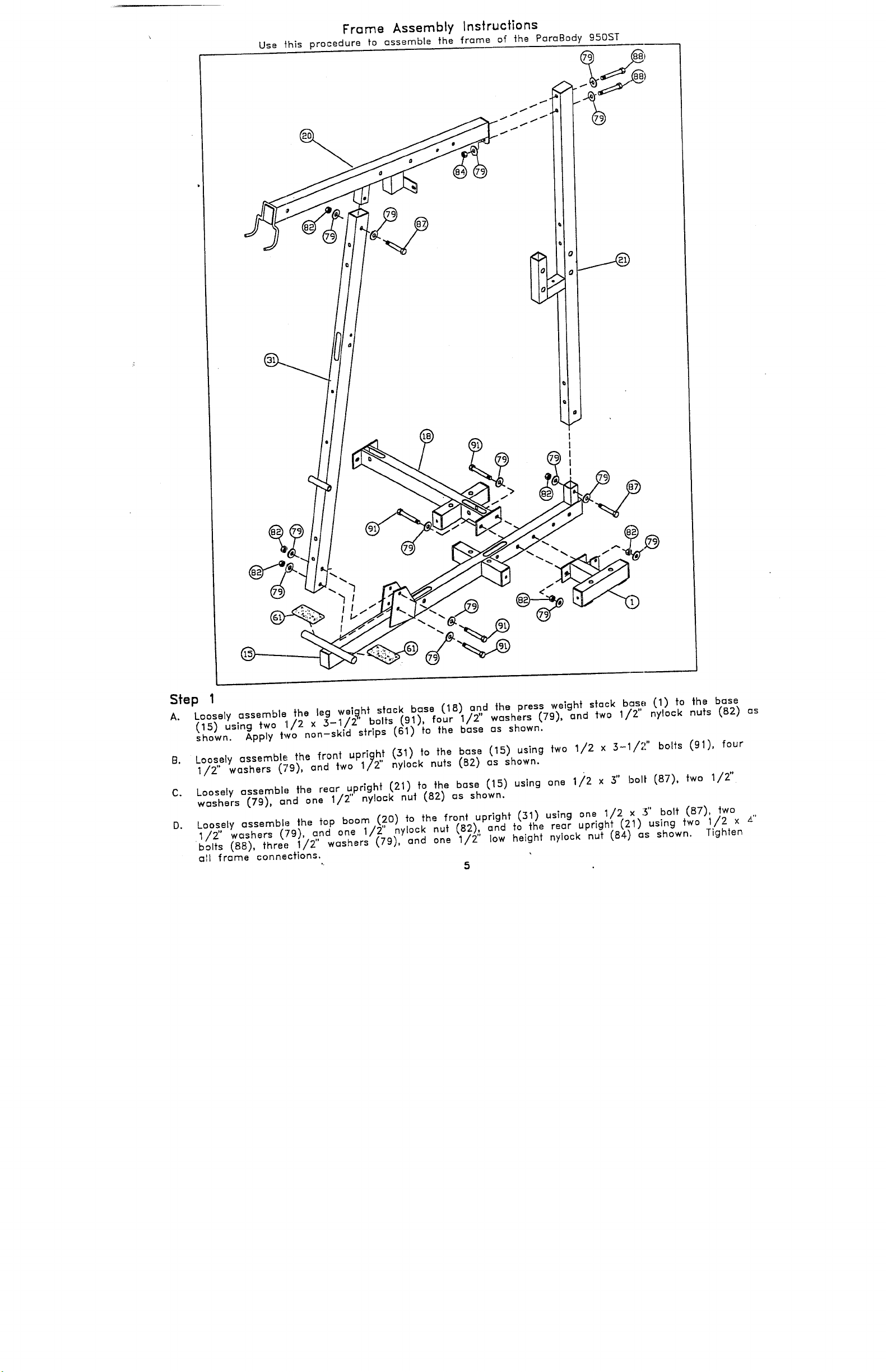
Frame Assembly Instructions
Use t’his procedure to ossemble the frame of the PareBody 950ST
Step 1
Loosely assemble the leg wei.~,ht stack bose (18) a.n,,d the press weight s~ack base (1) to the
A.
(15) using two 1/2 x .3-1/2 bolts (91), four 1/2 washers (79), and two 1/2" nylock nuts (B2)
~ho~n. Apply two non-skid s~rips (61) fo the base as shown.
Loosely assemble the front uprig~ (31) to the base (15) using two 1/2 x 3-1/2" bolts (91),
B.
1/2’ washers (79), and two 1/2 nylock nuts (82) as shown.
3"
Loosely ~ssembe the re~r ~,prighf (21) fo the b~se (15) using one li2 x bolt (87),
C.
w~shers (79), ~nd one 1/2 nyock nul (82) ~s shown.
D. Log~ly a,
1/Z wesners k~~},_~,
~1 frame connections.
ssembl: the fop boom (20) ~o fh~ front upright (31) using one 1/2 x 3" bolt (BT),
,’;~ --- --- ~/2" nvlock nut {82), and to the rear uprigh~ (~1) using two 1/2 x
u~
~’~ "~-_.. ~.~ ~/~,, low height nylock nut ~84) ~s shown.
5
/2"
Tighten
Page 6
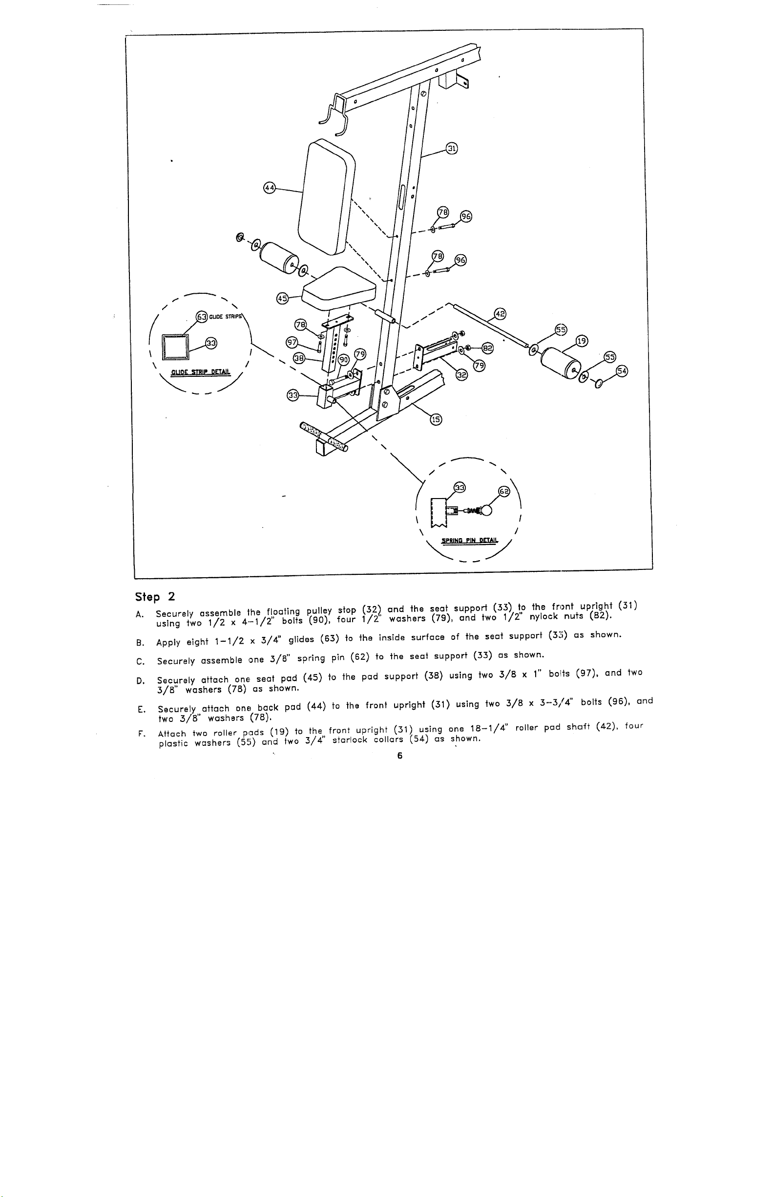
Step 2
Securely assemble the floating pulley stop (:52), and the s.eat support (33) to the front upright
A.
using two 1/2 x 4.-1/2" bolts (90), four 1/2’ washers (.79), and two 1/2" nylock nuts (B2).
Apply eight 1-1/2 x 3/4" glides (63) to the inside surface of the seat support (32;) as shown.
B.
Securely assemble one 3/8" spring pin (62) to the seat support (33) os shown.
C.
Securely attach one, seat pad (45) fo the pad support (38) using two 3/8 x bolts (97), and
D.
3/8" washers (78) as shown.
Securely attach one; back pad (44) to the front upright (31) using two 3/8 x 3--3/4" bolts (96),
E.
two 3/8" washers (78).
Attach two roller pads (19) to the front upright (51) using one 18-1/4" roller pad shaft (42),
F.
plastic washers (5.~) an two
="
d
3/4" sfarlock collars (54) as shown.
6
1"
Page 7
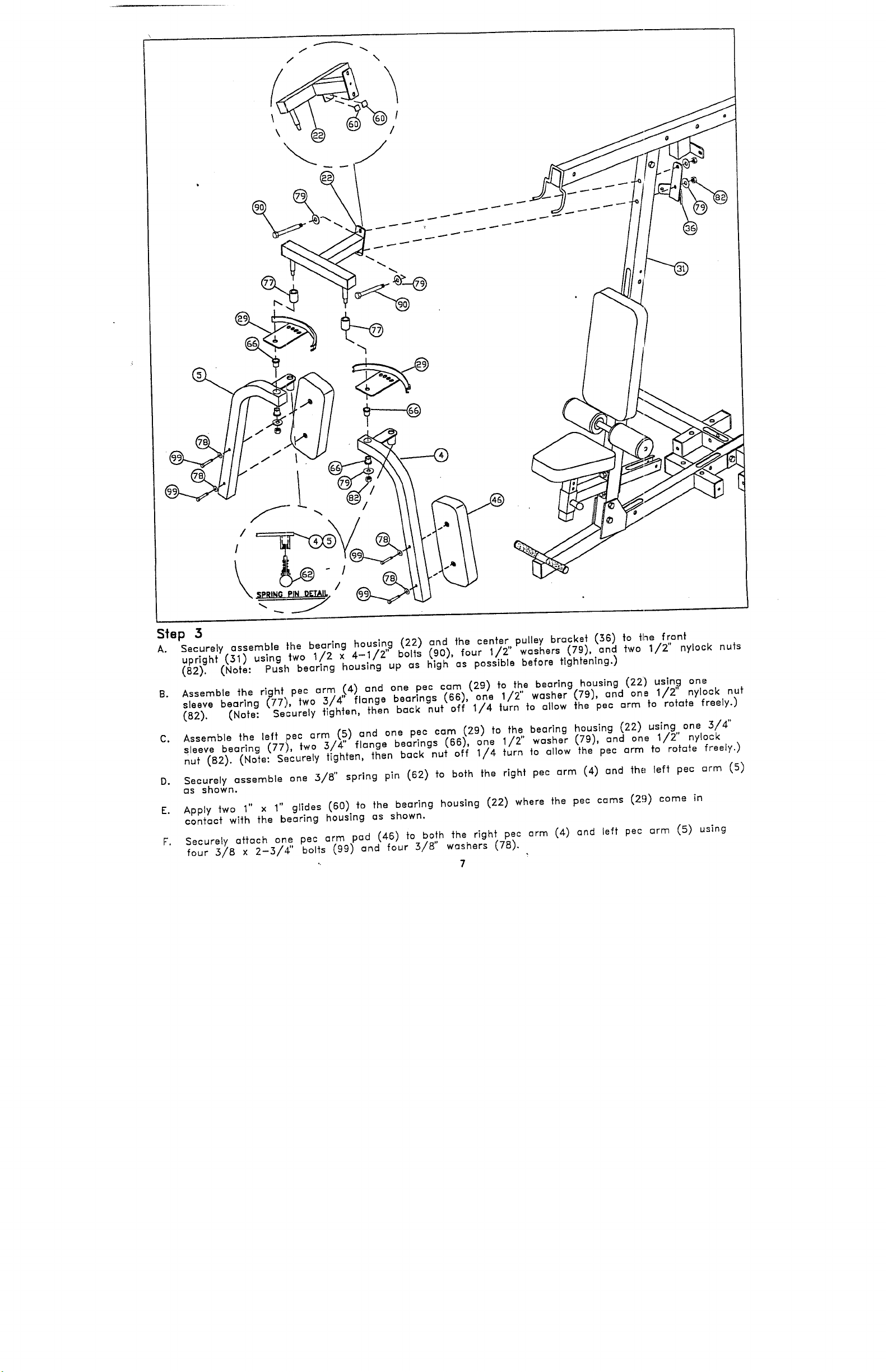
Step 3
Securely assemble the bearing housl.n,g (22) and the center, pulley bracket (36) to fine front
A.
upright (31) using two 1/2 x 4-1/2’ bolts (90), four 1/2’ washers (79), and two 1/2" nylock
(82). (Note: Push bearing housing up as high as possible before tightening.)
Assemble the right, pee arm ,I4) and one pec cam (29) to the bearing housing (22) using
B.
sleeve bearlng (77), two 3/4 flange bearings (66), one 1/2" washer (79), and ona 1/2" nylock
(82). (Note: Securely tighten, then back nut off 1/4 turn to allow the pec arm to rotate freely.)
Assemble the left pec arm (5) and one pec cam (29) to the bearing housing (22) using 3/4"
C.
sleeve bearing (77), two 3/4" flange bearings (66), 1/2" washer (79), and on e 1/ 2" n ylock
nut (B2). (Note: Securely tighten, then back nut off 1/4 turn to allow the pec arm to rotate freely.)
Securely assemble one 3/8" spring pin (62) to both the right pec arm (4) and the left pec arm
D.
as shown.
1"
E. Apply two 1" x
contact with the bearing housing as shown.
Securely attach one pec arm pad (46) to both the right pec arm (4) and left pec arm (5)
F.
glides
(60) to the bearing housing (22) where the pec cams (2!))
four 3/8 × 2-3/,~" bo~ts (99) and four 3/8" washers (78).
7
Page 8
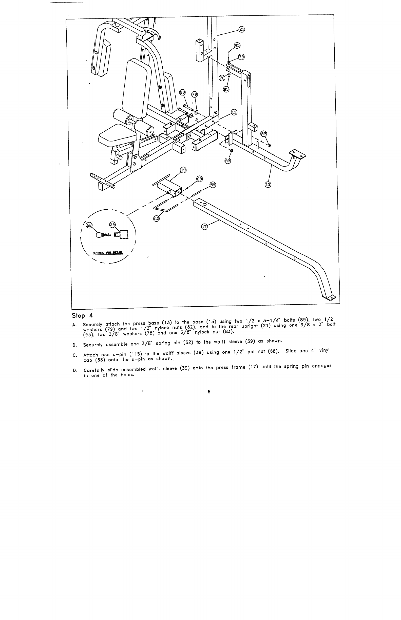
Siep 4 /2"
Securely attach fh~, press base (13) fo the base (15) using two 1/2 x 3-1/4" bolts (89),
A.
washers (79) ,~nd two 1/.2".nylock nuts .(8,2), and fo the rear upright (21) using one 3/8 x 3"
(95), two 3/8’ washers (,78) and one 3/8’ nylock
Securely assemble one :~/B" spring pin (62) to the wolff sleeve (39) as shown.
B.
Aftc~ch one u-pin (115) to the wolff sleeve (39) using one 1/2" pal nut (68). Slide
C.
cap (58) onto the u-pin as shown.
Cc~refully slide assembled wolff sleeve (39) onto the press frc~me (17) until the spring pin engages
D.
in one of the holes.
vinyl
Page 9

Step 5 ,
I
3’ bolts (95), two 1/2’ washers , 2’1
nylock nufs (831. (Note: Make
nLJt (1~2), and two 3/8"
Page 10

Slap 8
Slide two hinge tabs (73) onto the wolff sleeve (39) and securely attach press seat pad (49)
A.
two 3/B x bolts (97), and two 3/B" washers (7B). (Note:
should face upward.)
Slide the right back pad angle (2) and left back pad angle (3) onto the wolff sleeve (39)
B.
attach the press back pad (50) using four 3/8
Insert one 3/4 x 10-1/2" shaft (116) into the press base (13) as shown.
C.
Secure the press support tubes (40))~],ght back pad angle (2)and the left back pod angle
E.
using two 1/2 x
Secure nuts, then back off 1/4 turn.)
Center 3/4 x 10-1/2" shaft (116) and secure press suppoH tubes (40) using two 5/16 x 3/B"
F.
1"
1"
bol{s (97), and four 3/8" ~rashers (TB).
bolts (87), four
flange bearings (69), and
The "hinge" part of the hinge tab
two 1/2" nylock nuts (82).
screws
Apply one rubber bumber (56) to the back of the press back pad (50) where the pad comes
G.
contact with the rear bolt.
10
Page 11

Step 7
Loosely aftach the press arm odiu.s,,~ (23) to the rear up.r,!gh~ (21) using two 1" pillow block
A.
bearings (112), four 3/8 x 3-1/4 bolts (98), four 3/B’ washers (78), and
Center press arm adiust (23) to I~ne up w~th ~he post on the press base (13) and securely ~ighlen
B.
set screws on the pillow block bearings (112).
Adiusl pillow block bearings (112) until the press arm ad[us~ (23) is level and securely tighten
C.
bolls.
Securely assemble one 1/2" spring pln (64) to the press arm (6) as shown.
D.
s~u~ =.=~ ~e p~e.. ~=~) ~o ~.~ p~’" =~= ~iu~ (~) "’~ o~ ~/~ ~ ~-~/2" bo~ (~),
~wo 1/2" washers (79), ~wo 1 flange bearings (69), a,nd one 1/2" low height nylock
(Note: Securely tighten, then back nut off 1/4 turn to allow the press arm to rofcffe freely.)
r. s~u~.~y =,~h ~,~/~o~ ro~ (7) ~o ~h~ p~.,, b=~ (~3) u,~ng ~o ~/2 ~ ~" bo~, (~8), four
washers (79), and two
calf / low row a~s shown.
AHach swivel pulley bracket (41) fo the press base (13) using one 1/2" low height nylock
G.
(84). (Note: Securely tighten, ~hen back nu~ off 1/4 turn fo allow the swivel pulley bracket fo rotate
freely.)
low height nylock nuts (84). Apply ~wo non-skid z~frips (61)
/z"
11
~o the
Page 12

Step B
Securely attoch the rear leg base (10) ond the leg curl hondle (9) *o the leg frame (14) using
A.
1/2 × 3-1/4" bolts (Bg), t~.o .~/8 × 3-1/4". bolts (98), tour 1/2" washers (79), ~o,~r ~/B" washers
(TB), *wo 1/2" nylock nuts (,B2), and two 3/B" nylock nuts (,B3).
Securely attach two leg extension hand!es .(~5) fo the leg frame (14) using *wo 3/8 x 3-1/4 bolts
(9B), four 3/B" washers (78),
Securely assemble one 1/2" spring pin (64) *o *he leg frame (14) as shown.
Securely ~H~ch on~,,1/B x 2 x plate (37) fo ~he leg se~ p~d (47)
Page 13

STEP 9-B
STEP 9
A. Slide fwlo,, hinge tabs (73) onto the leg frame (14) and securely ah~ach leg seat pad (47) using
3/8 x
face downward.)
Attach two roller peels (19) to the leg frame (14) using one 15-3/4" roller pad shc, ff (27),
B.
plastic washers (55) and two 3/4" starlock collars (54) as shown
bolts (97), and two 3/B" washers (78). (Note: The "hinge" part of the ’hinge tab should
SE"E NOT ’
STEP 10
Attach leg back pad adjust (11), and leg back pad support (12) to the leg frame (14)
A.
one 1/2 x 5-1/2" bolt (92), two 1/2" flange bearings (69) and one 1/2" low he,ighf lock
as shown. (Note: ~.ecurely tighten, then
rotate freely.)
Securely attach the leg back pad (48) to the leg back pad adjust (11), and leg bc~ck pad
B.
support (12), using four 3/8 x 2-3/4’.’ bolts (99) and four 3/8" washers (78).
C. Securely attach leg curl/extension (8) to the leg frame (~14) using two 3/4" flange bearings
(S6), one 3/4" tapped axle (76), two 3/8" black lock washers (86), and two 3/8 x 1" black
button head cap screws (59).
~OTE: BOTH CAP :S~S M~T ~ TIGHT~D AT THE ~ T~E ~I~ TVO ~LEN V~~
D. Securely attach rubber bumper (56) between :ontac~ point o~ leg curl/extenslon (8) ~nd
frome (14) as shown.
back nut off 1/4 turn
I$
to allow the two F,ar~s to
Page 14

gEE ])ETA, IL
STEP 1 1
A.
Securely assemble two 3/8" spring pins (62) to the leg curl/extension (8) as shown.
B. Apply eight 1-1/2 x 3/4" glides (63) to the outside surfaces of each roller .pad adiuster (34)
shown, and insert roller pad adjusters (34) into the leg curl/extension (B). (.Note: The end caps
will need to be temporarily removed.) ,
C.
Securely assemble leg frame (14) to the leg weight slack base (18) using two x 3- 1/4" bolt s
(89), four 1/2" washers (79), and two 1/2 nylock nuts (B2).
D.
Attach. ,f, our roller pads (19) to the leg curl/extension (8) and roller pad adjusters (’34) using two
15-3/4 roller pad shafts (27), eight plastic washers (55) and four 3/4" starlock ,iollars (54) as
¯ -
14
Page 15

SEE NOTE
Step 1 2
Insert two plate bushings (102) into the "ParaBody" side of each of sixty weight plates (67)
A.
shown.
B. Insert one guide rod (28) through one weight stack cushion (109) and into each ef the large
holes in the base (15), the leg weight stack base (18), and the press weight stack press (1) as
Carefully slide twenty weight plates (67) onto each set of guide rods (28) wlfh the "ParaBody"
C.
side up and the center key-hole facing outward.
Securely assembe one selector,shaft (113) to one head plate (117) using one 5/8" block
D.
washer (86), and .one 3/8 x 1’ black button head cap screw (59). Repeat this step for the other two
head plates. (NOTE: THE BOLT HOLE IN THE HEAD PLATE SHOULD BE ON TOP)
Carefully slide one head plate assembly over each set of guide rods and onto each top weight
E.
plate as shown.
Insert one cap plug (57) into each guide rod (28).
F.
Apply one weight ~sfock label (118) onto each weight plate (67) as shown. Lc~bels 1 through
G.
should be applied from top to bottom of the weight stock and close to f~’,e key-hole.
15
.-,
Page 16

Step 1 3
Slide peo guide rod support ~4~,), onto ~he eo we]aht slack guide rods and loosely :ff~ach it
A.
fo the boom using tiwo 3/B
nuts (831¯ (Note: This connection will be secured in a la’ter step offer ~he pulleys
are assembled.)
bolts.(95), four 3/8" washers (781, and two 3/8 nylock
rods and securely Qssemble them fo lhe boom using two 1/2. x 3-1
washers (79), and t:wo 1/2" nylock nuts (82).
""
16
bolls (91), four
Page 17

PEC DEC%
" CABLE
’
CABLE GUIDE
STAMPED PART NUMBER
65356
//
77 5/8"
AB CRUNCH~
I.
,]
STAMPED
66274-
PART NUMBER
//
STAMPED PART NUMBER
66275
’ //
61 3/4"
STAMPED PART NUMBER
66276
LEG PRES S~Xx
CABLE
//
¯ £73 7/8"
STAMPED PART NUMBER
66277
169"
"
17
Page 18

Pec Dec Cable Assembly Instructions
Use this procedure to assemble ~he pec dec cables of the Pc~raBody 950ST
Step C
Step F & H
LAT
CABLE
Stel3 1 order, route the threaded end of the lot coble (~403~! through the top boom (20), the boise
A. ~r~5~h, iSend the Icrge hole in the pec guide rod support
Screw the threaded end of the lat cable (107) approximately 5/4" into the end of t’he selector
B.
shaft (113) and tighten jam nut securely as shown.
Securely assemble three 3-1/2" pulleys (111)_i~o the slots of ~he fop boom (20) using three
C.
2-3/4" bolls (99), six 3/8" Flmnge Spacers ~14), ~nd three 3/8" nylock nu~s (83). (Note: Loop
cable ~round each pulley prior to inseffing if into the slob)
Securely ~ssemble ~wo 3-1/2" pulleys (111) lnfo the slots of the base (15) using two 3/8
D.
2-3/4" bolls (99), four 3/8" Flonge Spacers (74), and two 3/8" nylock nuts (8~{). (Note: Loop
cable around e~ch pulley prior ~o inseffing if into the slot.)
securely lighten ~he bolts of the pec 9uide rod support (43) ~nd fop boom (20) connection ~f
E.
time. (Note: Center the pec guide rod suppo~ horizontally end vertically before tightening.
Apply two 1" x 1" glides (SO) to the flo~fing pulley (30), ~s shown.
F.
Securey assemble,one 4-1/2" pulle~ (110) ~o ~he flo~ting pulley stop (~2) using one 3/8 x 2-3/4"
G.
bolt (99), two 3/8’ flange spacers (74), and one 3/8" nylock nu~ (B3).
Securely assemble one 4-1/2" pulley (110),~o the flo~fing pulley (30) using 3,/8 x 2" bolt
H.
(100), ~wo 3/8" w,=shers (78), and one 3/8 nylock nut (83). Loop cable around pulley and
flo~fing pulley (30) onto the flo~fing pulley stop (32).
"’ 18
Page 19

Step 2
A. Conneot one end of the pec deo cable (104) to the slotted bushing on the right peo oam
(29). Route the other end of the pec dec cable around the front upright (31) and connect
to the slotted bushing on the left pec cam (29).
B. Securely assemble the pec dec cable (104) and tWO 4-1/2" pulleys (110) to the c-=nter
pulley bracket (36) uslng..t,,wo 3/8 x 2" b. olfs (100), two 2-7/8" ’L’ brackets (71), four
washers (78) and two 3/8 nylock nuts (.83). (Note: The pec dee cable should be routed
underneath the shorl leg of the ’L’ bracket. Also the ’L’ brackets should be positioned af a 45
degree angle to function properly.)
"
19
Page 20

\ \
Step 3
A.
Securely assemble l,~he ’U’ bracket (~26) fo the threaded end of the ab crunch c~ble (106) using
two 1/4" washers ~80) and two 1/4" nylock nuts (B1). (Note: Position the ’U’ br’ackef in ~he middle
of the thread as shown and "lock’-nuts together.)
B. Securely assemble ~he pec dec cpble (104) agd .one 3-I/2" pulley (111) ~o the ’U’ bracket (26)
one 3/8 x 2" bolt (I00), lwo 3/8" washers (78), and ,one 378" nylock nut (83). (Note: Loop
cable around the pulley prior to inse~ing if into the ’U brackel.)
Page 21

Step 4
Securely assemble tl~e ball end of the ab crunch cable (106) a,,nd one 3-1/2" pu. lle’/ (111) f.o,,fhe
A.
front upright (.51) using two 5/8 x 2-3/4" bolts (99), two .~/8 flange spacers f,74), two
washers (78), and two 3/8" nylock nuts (83). (Note: The ab crunch cable should ’be routed
underneath the relaining bolt as shown.)
Securely assemble ~he ab crunch cable. 1,10e) and one 4-1/2 pulley,,(110) t the floating pulley (30),
B.
usTng one 3/8 x 2 bat (100), two 5/8 washers (7B), and one 5/8 nylock nut (B3). (Note:
the cable around the pulley prior to inserting it into the floating pulley.)
If upon completion of assembly, the head plate (117) does not sit on fop of the first weight plate
C.
(67), push the head plate down, ;nsert the selector pin (72) and perform several repetitions af
station. This will relax the cable system and prevent the head plate from lifting up.
If after completing step E. the head plate still does not sit on fop of the first weight plate or if
D.
there is excess slack in the cable system, adjust the threaded end of the lat cable (107) accordingly
and retighfen the jam nut.
Page 22

Press Station Cable Assembly Instructions
Use this procedure to assemble the press station cable of the ParaBody gSI)ST
Step I
Secure ’~he ball end of the press cable (105) and two 3-1/2" pulleys (111) to ’~he swivel pulley
A.
bracket (41) using two 3/8 x 2" bolts (100), four 3/8" washers (78), and two 3/8" nylock nuts
(Note: Loop the cable around the pulley prior to inserting it into the swivel pulley bracket.)
Route the ~hreaded end of the press cable (105) through the large hole in ~he press frame (17)
and. secure to.the front slot of th2 press arm adjust (23) using one ~-1/2" pulley (’111),
3/8 x 2-3/4 bolt (99) two 3/8 flange spacers (74), and one 3/8 nylock nut (8~).
Loop the cable over the pulley prior fo inserting if inio the slot.)
Secure the press cable (19,~) and one 4’1/2" pulley (110) to,,~he press base (15), usfng one
Co
2-3/4" bolt (99), two 3/8 flange spacers (74), and one 3/8 nylock nut (83). (Note: Loop
cable under the pulley prior to inserting it into the slot.)~
Do
Secure the press cable (10-5) and one 3-1/2" pulley
(111) to the rear slot o!, the press arm adjust (23),
using one 3/8 x 2-3/4 b.o, lt (99), two 3/8" flange
spacers (74), and one 3/8’ nylock nut (83). (Note:
Loop the cable over the pulley prior fo inserffing Tf
into the slot.)
22
Page 23

S~ep 2
Secure the press cable (105) and two .~-1/2" pulleys
(111) to the pulley flats on the press base (15) and
press weight stack base (1) using two 3/8 x 2" bolts
78). and ’two .~/8" nylock nu,s(83). (Note: The press
cable should be routed underneath the short leg of the ’L’
bracket. Also the ’L’ brackets should be positioned
straight down ,o function properly.)
Secure ,he press cable (105) and one 3-1/2" pulley (111) to the press guide rod support
B.
using one 3/8 x 2-3/4" bolt (99). two 3/8" flange spacers (74). and one 3/8" nyl(>ck nut
(Note: Loop ,he cable over_the pulley prior to inserting it
Screw ,he threaded end of the press cable (105) approxima,ely 3/4" into the end of the
selec,or shaft (113) and ,[ghten ]am nu, securely as shown.
If upon completion of assembly, the head plate (117) does
no, sit on top of ,he firs, weight plate (67). push the head
pla,e down. insed ,he selector pin (72) and perform several
repetitions at the station. This will relax the cable system
and preven, the head pla,ed from lifting up.
sit on ~op of the firs, weight plate or if there is excess
slack in the cable sys,em, adjust ,he threaded end of the
cable accordingly arid retighten the iam nut.
23
Page 24

Leg Sfatlon Cable Assembly Instructions
Use this procedure to assemble the leg station cable of the PARABODY g50 ST
STEP 1
A.
Route the "loop" end of the leg cable (108) into the rear slot of the leg welght star< base (18)
behind the weight stack, and out through the slot near the leg station.
B. Securely attach th~,,"loop" end of the leg cable (108), to the cam on the leg curl/e>:fension (8),
using one 3/8 x bolt (97), two 3/8" washers (78), and one 3/8" nylock
Secure the leg cable (108) and one 3-1/2" pulley (111) to the pulley flat on the leg frame
C.
using one 3/8 x 2-1/,¢" b,olt (119), one 2-3/B ’L’ bracket (75), three 3/8" washer:, (7B), one
spacer (120), and one 3/8’ nylock nut (B3). (Note: The leg cable should be ro,,te,:l underneath
short leg of the ’L’ bracket and over the top of the pulley. Also the ’L’ bracket shc, uld be posffioned
af a 45 degree angle to function properly.)
g.
Secure the leg ca,hie (108.) and two 3-1/2
two 3/8 x 2-3/4’ bolts (9-9), four 3/8" flange spacers (74), and two 3/8" nylock nuts (B3).
Loop cable under the pulley prior to inserting if into the slot.)
Secure the leg cable (108~ and one 3-1/2’ pulley (111) fo
leg guide rod support (25) using one 3/8 x 2-3/4" bolt (99),
two 3/8" flange spac..ers (74), and one 3/8" nylock nut (83).
(Note: Loop the cable over the pulley prior to inserting it in
the slot.)
!’
pulleys (111) to the leg weight stack base (18) using
24
Page 25

STEP 2
A. Screw the threaded end of the leg cable (108) approximately 3/4" into the end of the selector
shall (115) and figh’~en [am nut securely as shown.
B. If upon completion of assembly, the head plate (117) does not sit on top of the firs]’ weight plate (67),
push the head plate down, insert the selector pin (72) and perform several repefifion;~ at the station.
This will relax the cczble system and prevent the head plated from lifting up.
If after completing s’tep B. the head plate still does not sit on top of the first weight plate or if
C.
there rs excess slack in the cable system, adiust the threaded end of the cable accordingly and
retighten the iam nuf.
_ Shroud Assembly Instructions
Use this procedure to assemble the shrouds of the ParaBody 950ST
Securely assemble the pec station shroud (51)
Ao
the pec guid~, rod support (43) and the base (15) using
four 5/8 x
blaok button head cap screws (59),
(Nofe-" The pec station shroud has no labels,)
25
Page 26

Securely assemble the,~ press station shroud (53)
the press guide rod .~upport (24) and the press weight stack
base (1) using four 3/8 x 1" black button head cap screws
(59).
diagram.)
Securely assemble the leg station shroud (52) fo the
leg guide rod suppor
using four 3/8 x 1" black buffon head cap screws (59).
(Note: The leg station shroud has the leg exercise diagram.)
(Note: The press station shroud has the press exercise
(25) and the leg weight stack base (18)
t
THIS
CONCLUDES THE ASSEMBLY OF THE PARABODY 950 ST GYM.
Please refer io the exercise diagrams for proper use of fhls pFoduct.
26
 Loading...