

Page 1
.~erious Steel
908101 ST LAT MACHINE
II I
ASSEMBLY INSTRUCTIONS
Part # 6677801
1
Revision: 02/24/97
Page 2
[IMPORTANT NOTES
I
There is a risk assumed by individuals who use this type of equipment. To rnin,imize risk, please
follow these rules:
1. Consult your physician before beginning any exercise program.
2. Inspect equipment daily. Tighten all loose connections and replace worn parts immediately.
Failure to do so may result in serious injury.
3. Do not allow minors or children to play on or around this equipment.
4. Exercise with care to avoid injury.
5. If unsure of proper use of equipment, call your loeal Parabody distributor or call the
Parabody customer service department at (800) 328-9714.
Please note:
* Thank you for purchasing the Parabody 908101 ST Lat Machine. Please,~ r,ead these
instructions thoroughly and keep them for furore reference. This product nust be assembled
on a flat, level surface to assure its proper function.
* We recommend cleaning your product (pads and frame) on a regular basis’,, using warm soap.v
water. Touch-up paint can be purchased from your Parabody customer service representative.
at (800) 328-9714.
[Tools Required for Assembly[
*
Rubber mallet or hammer
* 3/4" wrench
* 9/16" wrench
* Ratchet with 3/4" and 9/16" sockets
* Adjustable wrench
* Tape measure
[
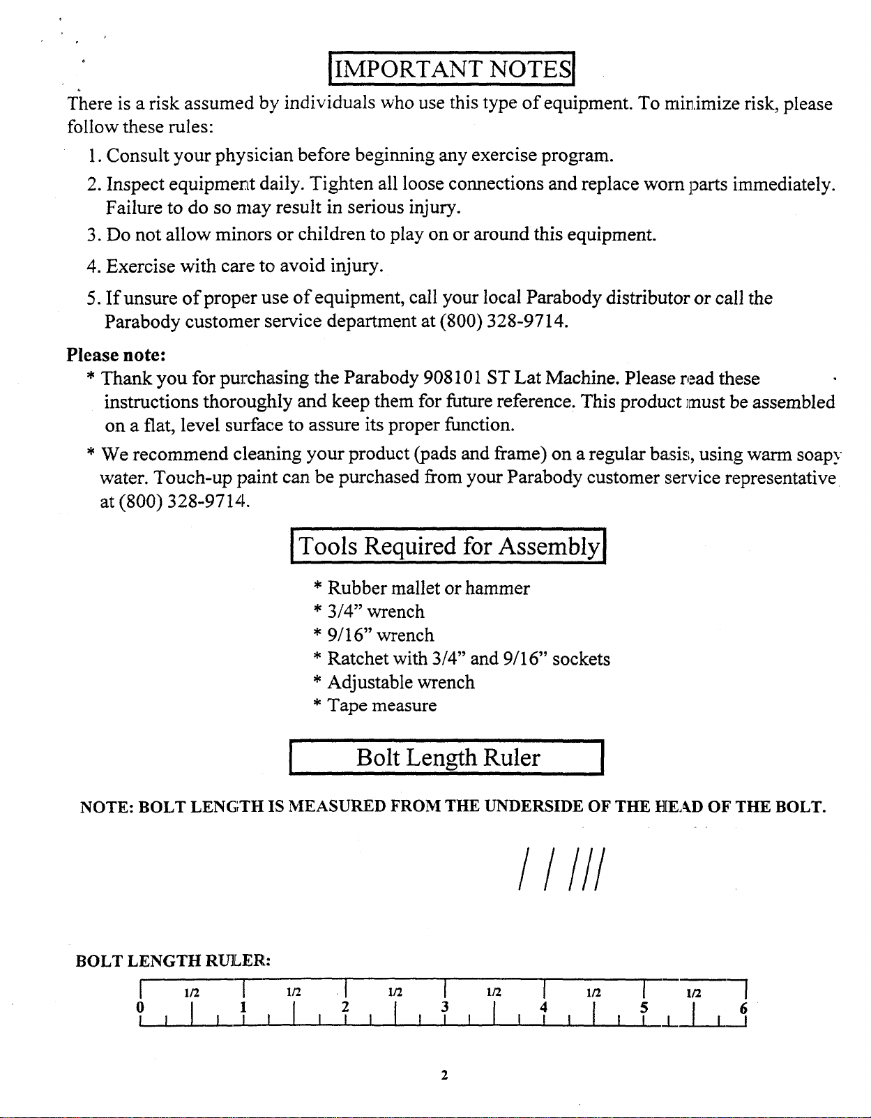
NOTE: BOLT LENG’rTH IS MEASURED FROM THE UNDERSIDE OF THE E~EAD OF THE BOLT.
Bolt Length Ruler
/////
BOLT LENGTH RULER:
[ 1/2 [ 1/2
0I I [ , ’ ’
¯ [ la [ 1/2 [ 1/2
4 $ 6
[ , , .L
[ 1/2 [
Page 3
[ PARTS LIST
KEY
1
2
3
4
5
6
7
8
9
I0
11
12
13
14
PART #
6673703
6672202
6674103
6674402
6(~72703
6674603
6z~89902 PLATE, 1/4 X 2 X 7-1/~
6621001
6678201 DOUBLE D CHROME HANDLE
6671601
6671001
3116101
3116201 3-I/2" PULLEY
DESCRIPTION
BENCH FRAME6671803
TOP BOOM
KNEE SUPPORT
UPRIGHT
FOOT SUPPORT
’" ~OWER
TOWER BRACE
CI2iROME LAT BAR
’121-3/4" (:ABLE ASSY
117-1/4" (:ABLE ASSY
~i..1/2;’ PULLEY
QTY KEY
1
1 16
I 17
1 18
1
1 20
1 21
2 22
1 23
1
1 26
3 27
4 28
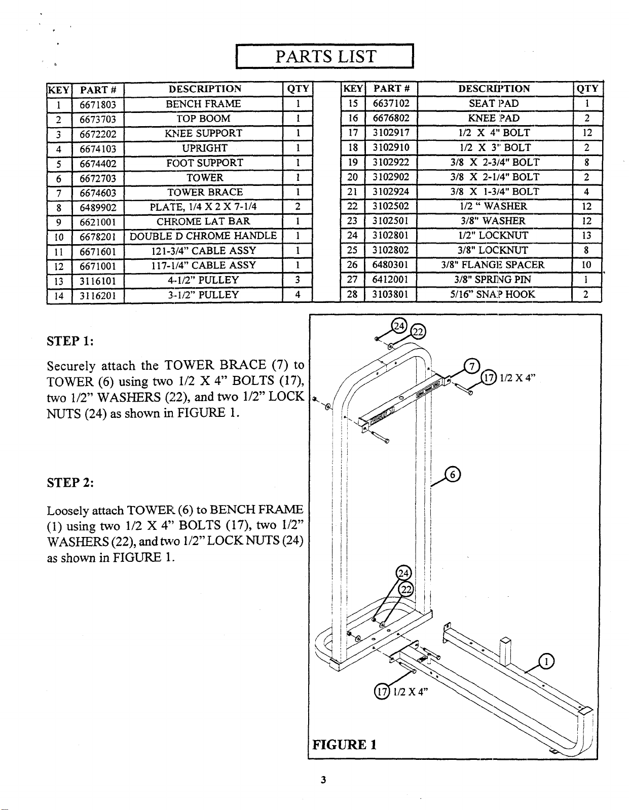
STEP 1:
Securely attach the TOWER BRACE (7)
TOWER (6) using two 1/2 X 4" BOLTS (17),
two 1/2" WASHERS (22), and two 1/2" LOCK
NUTS (24) as shown in. FIGURE
PART # DESCRIPTION
15
6637102 SE,~
6676802 KN~ PAD
3102917 1/2 X 4" BOLT
3102910 1/2’ ’X 3’" BOLT
19
3102~22
3102902 3/8 X 2-1/4" BOLT
3102924 3/8 X 1-3/4"BOLT
3102502 1/~ " WASHER
3102501 3/8" WASHER
24
3 I02801
3102802 3/8" LOCKNUT
6480301 3/8" FLAN SPACER
6412001 3/8" SPR/NG PIN
3103801 5/16" $1~ i? HOOK
3/8 X 2-3/4" BOLT
I/2" LOCKNUT
QTY
1
2
12’
2
8
2
4
12
12
13
8
I0
1
2
1/2 X 4"
STEP 2:
Loosely attach TOWER (6) to BENCH FRAME
(1) using two 1/2 X 4" BOLTS (I7), two
WASHERS (22), and two 1/2" LOCK NUTS (24)
as shown in FIGURE 1.
3
Page 4

FIGURE 2
STEP 3:
1/2 X 4"
1/2 X 4"
Loosely attach UPRIGHT (4) to BENCH FRAME (1) using four 1/2 X 4" BOLTS (17),
WASHERS (22), and fi3ur 1/2" LOCK NUTS (24) as shown in FIGURE
FIGURE 3
STEP 4:
Securely attach four 3-1/2" PULLEYS (14) to the TOP BOOM (2) using four 3/8 2-3/4" BOLTS (19),
eight 3/8" FLANGE SPACERS (26), and four 3/8" LOCK NUTS (25) as shown in FIGURE
1/2"
I I I
2 3 4
I I I I [ I I I [ I I.L.,[ I__l
4
5 60 1
Page 5

1/2 X 4"
1/2 X 4"
FIGURE 4
STEP 5:
A. Loosely attach TOP BOOM (2) to TOWER (6) and UPRIGHT (4) using 1/2 X4" BOLTS (17),
four 1/2" WASHERS (22), and three 1/2" LOCK NUTS (24) as shown in FIGURE
B. Securely tighten all loose frame connections made to this point.
1/2 X 3"
FIGURE 5
3/8 X 2-3/4"t
STEP 6:
A. Securely attach FOOT SUPPORT (5) to the BENCH FRAME (1) using two 1/2 X 3" BOLTS (18),
two 1/2" WASHERS (22), and two 1/2" LOCK N~TS (24) as shown in FIGURE
B. Securely attach SEAT PAD (15) to the BENCH FRAME (1) using two 3/8 X 2-3/4" BOLTS (19)
two 3/8" WASHERS (23) as shown in FIGURE
Page 6

FIGURE 6
STEP 7:
A. Securely attach two KNEE PADS (16) to KNEE SUPPORT (3) using four 3/8 IX 1-3/4" BOLTS
and four 3/8" WASHERS (23). See FIGURE
B. Slide KNEE SUPPORT (3) over square tube on BENCH FRAME (1). Make sure SPRING
HOUSING on the K~NEE SUPPORT (3) is facing away from the SEAT PAD. See FIGURE 6 &
STEP 8:
Securely thread 3/8" SPPd[NG PIN (27) to the
SPRING PIN HOUSING on the KNEE SUP-
PORT (3) as shown in FIGURE
0
I I
[ I I I
FIGURE 7
I I I I [ I 1.1_] I__1
4
5 62 3
Page 7

STEP 9:
Assemble two 7-1/4" PLATES (8) to two 4-1/2" PULLEYS
(13) using two 3/8 X 2-1/4" BOLTS (20), four
WASHERS (23), and two 3/8" LOCK NUTS (25).
FIGURE 8.
FIGURE
FIGURE 9
STEP 10:
Securely assemble one 4-1/2" PULLEY (13) to the UPRIGHT (4) using two 3/8 X 2,-3/4" BOLTS (19),
two 3/8" FLANGE SPACERS (26), two 3/8" WASHERS (23), and two 3/8" LOCK NUTS (25).
FIGURE 9.
THIS CONCLUDES THE ASSEMBLY OF THE 908101. PLEASE REFER TO THE 912101 OR
913101 INSTRUCTIOHS ON HOW TO ASSEMBLE TIlE WEIGHT OPTION.
 Loading...