


Operating Instructions
Extension Software
Model No. WV-SAE200, WV-SAE100
WV-SAE200W, WV-SAE100W
Before attempting to connect or operate this product,
please read these instructions carefully and save this manual for future use.
The model number is abbreviated in some descriptions in this manual.
CONTENTS
Preface ....................................................................................................................................................................3
Features...............................................................................................................................................................3
About notations ................................................................................................................................................... 3
About the user manuals ...................................................................................................................................... 4
System requirements ..........................................................................................................................................4
Trademarks and registered trademarks ..............................................................................................................4
Abbreviations ......................................................................................................................................................4
Before using this product
Operations flow ....................................................................................................................................................... 6
Before purchasing ............................................................................................................................................... 6
How to obtain and register the Registration Key ....................................................................................................7
How to obtain and register the Registration Key
How to obtain and register the Registration Key
About the extension software window
Unique information ............................................................................................................................................ 11
Extension Software ...........................................................................................................................................12
Upgrade the Extension Software ......................................................................................................................12
Advanced func. (Face detection function)
Setup menu ....................................................................................................................................................... 13
Configure the setting relating to the image recognition [Advanced func.] ........................................................14
i-VMD function
About "Live" page when the i-VMD function is activated ................................................................................. 17
Enable the i-VMD function [Alarm] .................................................................................................................... 18
Configure the settings relating to i-VMD [i-VMD]
Configure the settings relating to i-VMD [i-VMD]
Configure the settings relating to the detection mode/area [Detection mode/area] ......................................... 25
Set the detection depth ..................................................................................................................................... 29
Set the line for people count [Line] ................................................................................................................... 30
Set the i-VMD schedule [Schedule] .................................................................................................................. 32
Configure the settings relating to Panasonic alarm protocol [Panasonic alarm protocol] ................................ 33
Configure the advanced settings relating to the i-VMD function [Advanced settings] .....................................34
SAE200
SAE200
.......................................................................................................................... 5
TYPE1
TYPE2 TYPE3 TYPE4 TYPE5 TYPE6 TYPE8
TYPE2 TYPE3
TYPE1 TYPE2
........................................................................................................................................ 16
TYPE1 TYPE2
TYPE3
................................................................................. 7
TYPE4 TYPE5 TYPE6 TYPE8
TYPE4
TYPE5 TYPE8
................................................................. 13
TYPE4 TYPE6
.................................................. 20
............................ 11
.................................... 19
.......... 9
2 3
Preface
The Extension Software WV-SAE200, WV-SAE200W, WV-SAE100, and WV-SAE100W (hereinafter, this product)
are designed to enhance the usefulness of optional network cameras.
After registering the software, it is possible to use the following functions: the face detection function and the
i-VMD function (alarm functions: intrusion detection/ loitering/ direction detection*/ scene change/ object detection*/ cross line detection*, the analysis data control function: people count/heat map, and the privacy function:
MOR (Moving Object Remover)).
Important:
• This product is required per camera.
• Refer to the following URL for details.
https://security.panasonic.com/kms/
• About the heat map function
The heat map images cannot be seen with the functions of this product alone. The heat map functions will
be available when our video management software WV-ASM200
TYPE8
is used with this product.
TYPE3
Features
• Face detection function*: It is possible to detect people's faces and display the face detection frames. It is
also possible to add the function to notify the information of detected faces in the XML format.
In combination with the Network Disk Recorder or the Additional Business Intelligence Kit, it is possible to
use the face matching function.
• Alarm function
change/ object*/ cross line*.
With the i-VMD alarm function, it will become possible to set more detailed alarm detection conditions com-
pared with the conventional VMD function. For example, an alarm can be issued when the motion of an
object meets the specified conditions.
• People count*/Heat map*
people and statistical information of trafc lines.
• MOR (Moving Object Remover)*
image and only send the background image.
SAE200
: It is possible to add the detection function for intruder/ loitering/ direction*/ scene
SAE200
: Using i-VMD function, it provides function of counting the number of
SAE200
: It is a privacy-conscious function which removes people from the
or WV-ASM300
TYPE3 TYPE5
* In the above URL, check the models that support this function.
About notations
The following notations are used when describing the functions limited for specified models.
The functions without the notations are supported by all models.
Notation
SAE200
SAE100
For further information about the functions restricted depending on network camera models, refer to the oper-
ating instructions of the network cameras in use.
The following marks indicate that the type of the camera of which operating procedure may vary or functions
may be limited on use depending on the type (TYPE1, TYPE2, TYPE3, TYPE4, TYPE5, TYPE6, TYPE8) of the
network camera.
The operating procedure without this mark is for all models of network cameras.
The functions without this mark are supported by all models of network cameras.
TYPE1
TYPE2
TYPE3
TYPE4
TYPE5
TYPE6
TYPE8
* Refer to the following URL for the models of TYPE1, TYPE2, TYPE3, TYPE4, TYPE5, TYPE6, and TYPE8
network cameras. https://security.panasonic.com/kms/
The functions with this notation are available when using the model WV-SAE200 or WV-SAE200W.
The functions with this notation are available when using the model WV-SAE100 or WV-SAE100W.
: Indicates the operating procedure and the functions only for TYPE1 network cameras.
: Indicates the operating procedure and the functions only for TYPE2 network cameras.
: Indicates the operating procedure and the functions only for TYPE3 network cameras.
: Indicates the operating procedure and the functions only for TYPE4 network cameras.
: Indicates the operating procedure and the functions only for TYPE5 network cameras.
: Indicates the operating procedure and the functions only for TYPE6 network cameras.
: Indicates the operating procedure and the functions only for TYPE8 network cameras.

About the user manuals
This PDF manual contains how to register this product in network cameras, how to configure the required settings before starting running the software and how to operate the software.
This product is intended for the use after the registration in network cameras. Be sure to refer to the operating
instructions of the network cameras in use together with this manual.
The illustrations of the screens of the network camera used in these operating instructions may be different
depending on the network camera in use.
"WV-SAE200" shown in the instructions and illustrations used in this manual indicates the WV-SAE200,
WV-SAE200W.
"WV-SAE100" shown in the instructions and illustrations used in this manual indicates the WV-SAE100,
WV-SAE100W.
Adobe® Reader® is required to read these operating instructions (PDF) on the provided CD-ROM.
When the Adobe® Reader® is not installed on the personal computer (hereinafter, PC), download the latest
Adobe® Reader® from the Adobe web site and install it.
System requirements
For further information about the system requirements for the operation from the PC, refer to the operating
instructions of the network cameras in use.
Trademarks and registered trademarks
• Adobe and Reader are either registered trademarks or trademarks of Adobe Systems Incorporated in the
United States and/or other countries.
• Microsoft product screen shot(s) reprinted with permission from Microsoft Corporation.
• All other trademarks identied herein are the property of their respective owners.
Abbreviations
The following abbreviations are used in these operating instructions.
Network disk recorders are described as recorders, and network cameras as cameras.
4 5

Before using this product
• The motion detection function will not effectively work in the following situations or may sometimes be malfunctioning.
• There is no difference in luminance level between the moving object and background.
• Luminance level of image is too low (During nighttime, etc.)
• Movement of object is too fast or too slow.
• Object is too big or too small.
• Luminance level of shooting area is subject to change (outdoors, by the window, etc.)
• Outside light (sunlight, headlights, etc.) enters the shooting area.
• Fluorescent light is ickering.
• Depth of object is too long.
• Dirt, drip, or splash is on the dome cover of camera.
• The subject is moving directly toward the camera.
• Too many objects are moving.
• Camera is shaking.
• Weather condition is extremely poor.
• Several people are crossing with each other.
• The detection area is blocked with shadows.
• When there are factors for false detection such as shaky trees, driveways lled with cars or water surfaces
reecting light in the shooting area, it is possible to reduce the false detection by setting mask areas
(☞page 27).
• To enhance the detection accuracy, it is recommended to use the system in the following installation environment.
• Set the angular eld of view on the operation window in order to make the detection target to the following size in each aspect ratio.
- When the aspect ratio is "4:3", adjust the angular eld of view to make the size of the detection target
to approx.1/6 to 1/3 (vertical direction).
- When the aspect ratio is "16:9", adjust the angular eld of view to make the size of the detection target to approx.1/4 to 1/3 (vertical direction).
- When the aspect ratio is "9:16", adjust the angular eld of view to make the size of the detection target to approx.1/4 to 1/3 (vertical direction).
- When the aspect ratio is "1:1" (TYPE3/TYPE5/TYPE8) and the camera is installed on the wall, adjust
the angular eld of view to approx.1/8 to 1/4.
When the camera is to be installed on the ceiling, install at the height of 2.5 m to 4.0 m.
• Specify the size of the objects to be detected by setting the depth (☞ page 29). *
• When conguring the i-VMD settings, set the detection area (☞ page 26) and check the performance in the
daytime and nighttime.
• In the following cases, scene change may not be detected.
• Only a part of the shooting area is covered or the covered object can be seen.
• Subjects look alike each other before and after the camera direction has been changed.
• For 1 minute after the power is turned on, the camera settings are changed or the angular eld of view is
changed for the camera, false detection may occur.
• When there is a detection target in the shooting area, alarm will repeatedly occur at a specied interval.
Therefore, the mail notication and the notication using the Panasonic alarm protocol will also be repeated
at the specied interval.
• When using the i-VMD function, the frame rate of H.265/H.264 images may become lower.
• In no event shall Panasonic i-PRO Sensing Solutions Co., Ltd. be liable to any party or any person for any
problem, consequential inconvenience, or loss or damage, arising out of the i-VMD settings.
• i-VMD is not a function to prevent theft or re. In no event shall Panasonic i-PRO Sensing Solutions Co., Ltd.
be liable to any party or any person for any accidents or loss.
SAE200
* The depth setting is not available for TYPE3, TYPE5, and TYPE8.
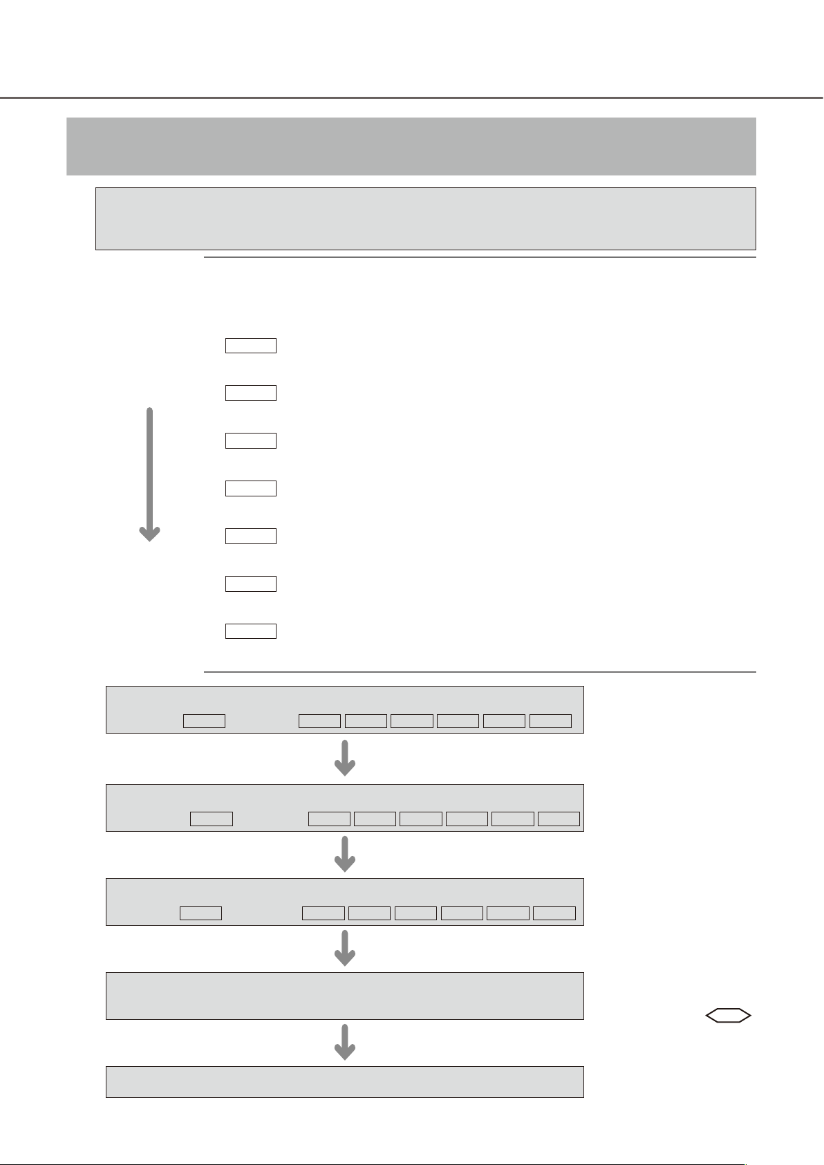
Operations flow
Before purchasing
Check the compatible models and software versions in the following URL when
registering the Extension Software.
https://security.panasonic.com/kms/
Note:
• The operating procedure and the screens for installation of the Extension Software
and the extension software le may vary depending on the type (TYPE1, TYPE2,
TYPE3, TYPE4, TYPE5, TYPE6, TYPE8) of the network camera.
• There are 7 types of the extension software les as follows. Check the le name.
TYPE1
Use the file whose name does not include "type2", "type3", "type4", "type5", "type6",
or "type8".
TYPE2
Use the file whose name includes "type2". (Example: SAE200_v100_type2.ext)
This corresponds to TYPE2 camera.
TYPE3
Use the file whose name includes "type3". (Example: SAE200_v100_type3.ext)
This corresponds to TYPE3 camera.
TYPE4
Use the file whose name includes "type4". (Example: SAE200_v100_type4.ext)
This corresponds to TYPE4 camera.
TYPE5
Use the file whose name includes "type5". (Example: SAE200_v100_type5.ext)
This corresponds to TYPE5 camera.
TYPE6
Use the file whose name includes "type6". (Example: SAE200_v100_type6.ext)
This corresponds to TYPE6 camera.
TYPE8
Use the file whose name includes "type8". (Example: SAE200_v100_type8.ext)
This corresponds to TYPE8 camera.
(Example: SAE200_v100.ext) This corresponds to TYPE1 camera.
1
2
3
4
☞ page 7
☞ pages 7-8
☞ page 8
TYPE1
TYPE1
TYPE1
Install the Extension Software
☞ page 9
TYPE2 TYPE3 TYPE4 TYPE5 TYPE6 TYPE8
Obtain the Registration Key
☞ page 10
TYPE2 TYPE3 TYPE4 TYPE5 TYPE6 TYPE8
Register the Registration Key
☞ page 10
TYPE2 TYPE3 TYPE4 TYPE5 TYPE6 TYPE8
Perform the required settings
☞ pages 13-35
Start operations
Register the Registration
Key obtained in Step 2 in
the cameras.
Configure the settings
relating to the face
detection or i-VMD
SAE200
.
6 7
How to obtain and register the Registration Key
This product needs to be activated by "Registration Key" issued by Key Management System before you start
using.
The registration of the Registration Key is only operable by users whose access level is [1. Administrator].
Refer to the operating instructions of the camera for how to configure the access level.
How to obtain and register the Registration Key
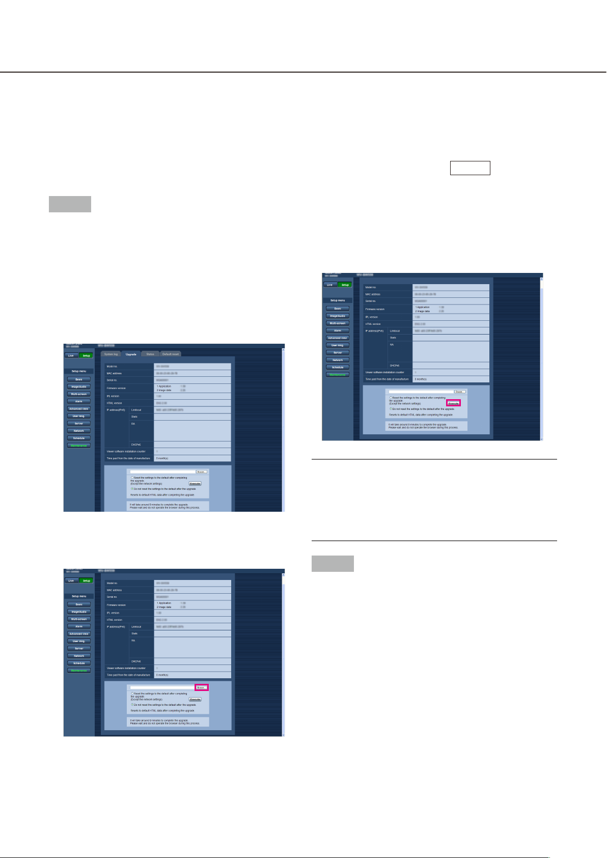
Step 1
Install the Extension Software.
(1) Access the following URL to download the
Extension Software and save it onto the PC.
https://security.panasonic.com/kms/
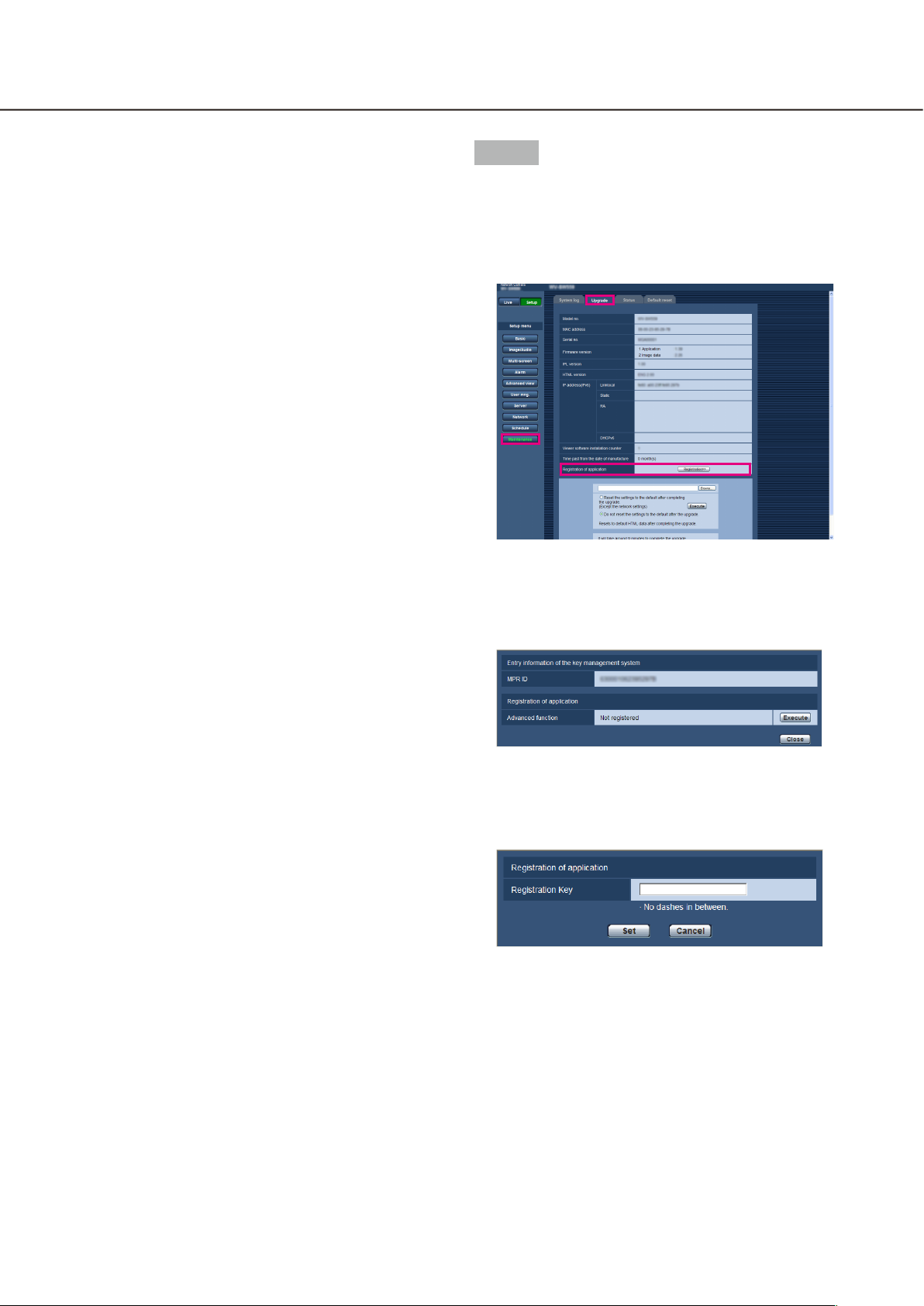
(2) Access the camera, and display the setup menu -
the "Maintenance" page - the [Upgrade] tab by
clicking the corresponding buttons and tab.
(4) Click the [Execute] button.
The installation of the Extension Software will
start.
When the installation is completed, the camera
will automatically restart.
TYPE1
(3) Click the [Browse...] button and designate the
downloaded extension software.
Important:
• Use the le (with an ".ext" extension) specied by
Panasonic when installing the Extension Software.
• Do not turn off the power of the camera when installing the software. Do not perform any operations until the installation is completed.
Step 2
Obtain the Registration Key.
(1) Check the MPR ID, Activation Key No. and
Registration ID.
Access the camera, and display the setup menu -
the "Maintenance" page - the [Upgrade] tab by
clicking the corresponding buttons and tab.
Click "Registration of application" -
"Registration>>" to display the "Entry information
of the key management system" page, and check
the MPR ID.
* The MPR ID can also be checked on the product
package.
The Activation Key No. and Registration ID are
shown on the Activation Key Card.
(2) Please access and login to the following URL
"Key Management System" from your PC or
Mobile Phone.
For PC: https://kms.business.panasonic.net/
ipkms/pc/home.htm
Temporary User ID: kmsadmin_reg
Password: hpynBaxb
* If this temporary User ID and password does not
work, go to the above URL to check the latest
temporary User ID and password.
For mobile: https://kms.business.panasonic.net/
cgi-bin/ipkms/m-key/license.cgi?MODE=key_
login (To issue the "Registration Key" only.)
* Certain mobile phone are not compatible with
"Key Management System".
* You may not access "Key Management System"
for server maintenance without notice.
(3) Please create your User ID and password, if it is
the first time to access this system.
Please login as a temporary user using the User
ID and password written on the web page.
Please register required information and create
your account.
Step 3
Register the Registration Key.
(1) Access the camera, and display the setup menu -
the "Maintenance" page - the [Upgrade] tab by
clicking the corresponding buttons and tab.
(2) Click "Registration of application" -
"Registration>>" to display the "Entry information
of the key management system" page.
(4) Enter the registered User ID and password on the
"Key Management System" for login.
(5) Enter "MPR ID", "Installation Site Information",
"Activation Key No." and "Registration ID" by following the instructions displayed on the monitor.
(6) The Registration Key will be issued.
Note it down on the Activation Key Card, and
keep the card so as not to lose.
(3) Click the [Execute] button of "Registration of
application" to display the "Registration of application" page.
(4) Enter the Registration Key obtained in Step 2 in
the "Registration Key" field, and click the [Set]
button.
After the Registration Key is registered, the
Extension Software will be validated.
Enter the Registration Key without the hyphens (-).
* Check the compatible models in the following
URL when registering the application.
https://security.panasonic.com/kms/
* To uninstall the extension software, it is neces-
sary to reset to the factory shipping state.
8 9
How to obtain and register the Registration Key
TYPE2 TYPE3 TYPE4 TYPE5 TYPE6 TYPE8
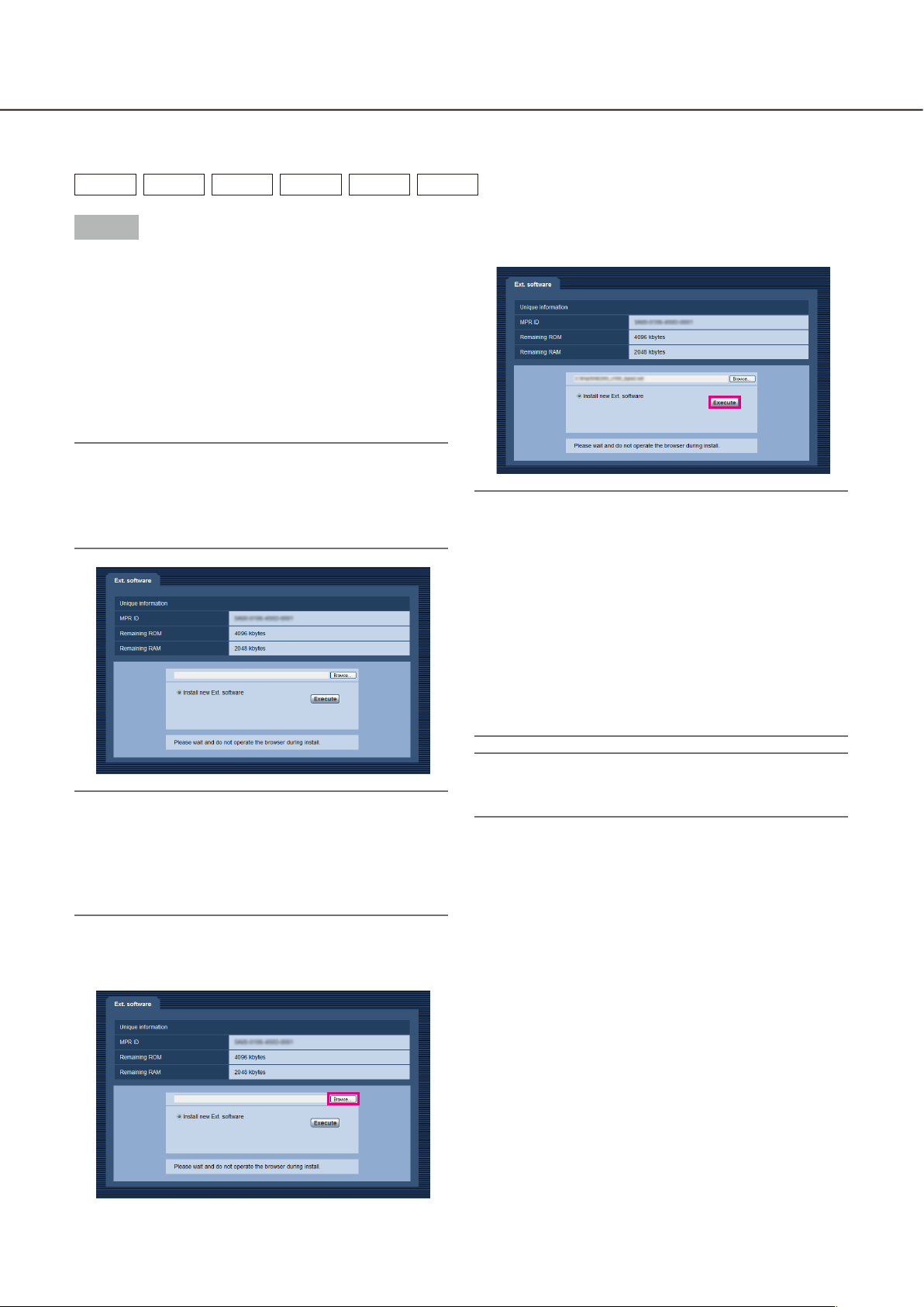
Step 1
Install the Extension Software.
(1) Access the following URL to download the
Extension Software and save it onto the PC.
https://security.panasonic.com/kms/
(2) Enter the following URL on the web browser.
http://(the IP address of the camera)/admin/
setup_ext_software.html
Note:
• The "Ext. software" page can be displayed by
clicking the [Ext. software >>] button accessing
from the setup menu - the "Maintenance" page the [Upgrade] tab.
(4) Click the [Execute] button. The installation of the
Extension Software will start.
Important:
• Double-byte characters cannot be used for the
name of the saving directory.
• Use the le (with an ".ext" extension) specied by
Panasonic when installing the Extension Software.
• Do not turn off the power of the camera when installing the software. Do not perform any operations until the installation is completed.
• If installation fails, information of the Extension
Software will not be displayed. Check the ROM/
RAM volume of the Extension Software and the
camera version.
Important:
• Check "Remaining ROM" and "Remaining RAM"
of the camera. When the other extension software
is already installed, it is necessary to uninstall it or
prepare another camera. Refer to page 12 for further information about uninstallation.
(3) Click the [Browse...] button and designate the
downloaded extension software.
Note:
• No trial period is provided for the face detection
or i-VMD function.
Step 2
Obtain the Registration Key.
(4) Enter the registered User ID and password on the
"Key Management System" for login.
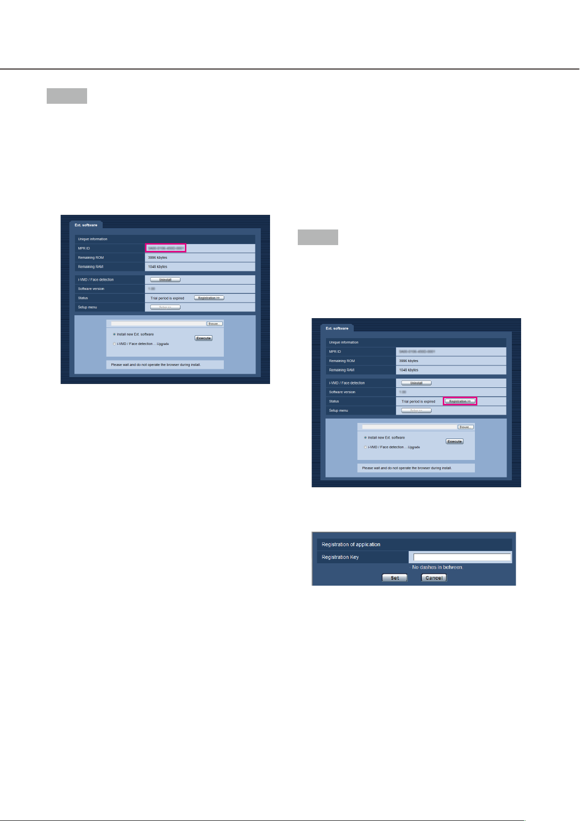
(1) Check the MPR ID, Activation Key No. and
Registration ID.
• Enter the following URL in the browser and
check "MPR ID".
http://(the IP address of the camera)/admin/
setup_ext_software.html
* The MPR ID can also be checked on the
product package.
• The Activation Key No. and Registration ID are
shown on the Activation Key Card.
(5) Enter "MPR ID", "Installation Site Information",
"Activation Key No." and "Registration ID" by following the instructions displayed on the monitor.
(6) The Registration Key will be issued.
Note it down on the Activation Key Card, and
keep the card so as not to lose.
Step 3
Register the Registration Key.
(1) Enter the following URL in the browser.
http://(the IP address of the camera)/admin/
setup_ext_software.html
(2) Please access and login to the following URL
"Key Management System" from your PC or
Mobile Phone.
For PC: https://kms.business.panasonic.net/
ipkms/pc/home.htm
Temporary User ID: kmsadmin_reg
Password: hpynBaxb
* If this temporary User ID and password does not
work, go to the above URL to check the latest
temporary User ID and password.
For mobile: https://kms.business.panasonic.net/
cgi-bin/ipkms/m-key/license.cgi?MODE=key_
login (To issue the "Registration Key" only.)
* Certain mobile phone are not compatible with
"Key Management System".
* You may not access "Key Management System"
for server maintenance without notice.
(3) Please create your User ID and password, if it is
the first time to access this system. Please login
as a temporary user using the User ID and password written on the web page.
Please register required information and create
your account.
(2) Click the [Registration >>] button and display the
"Registration of application" window.
(3) Enter the Registration Key obtained in Step 2 in
the "Registration Key" field, and click the [Set]
button. After the Registration Key is registered,
the Extension Software will be validated. Enter the
Registration Key without the hyphens (-).
* Check the compatible models in the following
URL when registering the application.
https://security.panasonic.com/kms/
10 11
TYPE2 TYPE3
TYPE4 TYPE5
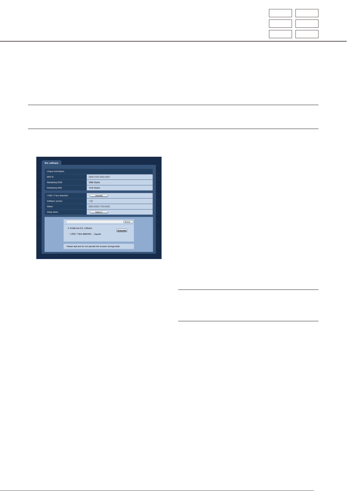
About the extension software window
When the installation of the Extension Software is completed, registration status of the Extension Software and
unique information will be displayed. The following operations are available on this window.
• Uninstallation of the Extension Software
• Display of the detailed registration status window
• Display of the extension software setting window
• Updating of the Extension Software
Note:
• It is possible to install up to 2 extension software.
• It is impossible to run multiple extension software concurrently.
TYPE6 TYPE8
Unique information
[MPR ID]
This ID is required to run the Extension Software.
Each camera has a unique one.
[Remaining ROM]
Remaining capacity of ROM in the camera to be used
for the Extension Software will be displayed. When
the Extension Software to be installed requires ROM
capacity more than the capacity displayed here, it is
impossible to install it.
[Remaining RAM]
Remaining capacity of RAM in the camera to be used
for the Extension Software will be displayed. When
the Extension Software to be installed requires RAM
capacity more than the capacity displayed here, it is
impossible to install it.
Note:
• Capacity that the Extension Software can use may
vary depending on the model or version of camera.

Extension Software
[Uninstall] button
It is possible to uninstall the installed extension software.
[Software version]
When the Extension Software is installed, version
information of the installed extension software will be
displayed.
[Status]
When the Extension Software is installed, registration
status of the installed extension software will be displayed.
xxxx-xxxx-xxxx-xxxx: When the registration key is
displayed, registration of the installed extension
software is completed. When the registration is
completed, it is possible to run the Extension
Software.
[Setup >>] button
When the Extension Software has a unique window
such as a setting window, etc., it is possible to display it.
Upgrade the Extension Software
Select the installed extension software, and then click the [Execute] button to upgrade the Extension Software.
Important:
• The i-VMD alarm function of the TYPE2, TYPE3, TYPE4, TYPE5, TYPE6, and TYPE8 camera cannot be used
only by installing the extension software. To enable the i-VMD alarm function of the TYPE2, TYPE3, TYPE4,
TYPE5, TYPE6, and TYPE8 camera, make sure to set up the i-VMD schedule in the "Schedule" page.
(☞ page 32)
12 13

Advanced func.(Face detection function)
TYPE1 TYPE2 TYPE4
Setup menu
When the application for the advanced func. (face detection function) is added, the [Advanced func.] button will
be displayed.
[Advanced func.] button
Display the "Advanced func." page. The settings relating to the XML notification, the destination of information
relating to the face detection and the settings relating to the face detection can be configured on the
"Advanced func." page.

Configure the setting relating to the image recognition [Advanced func.]
The settings relating to the XML notification and the settings relating to the face detection can be configured on
the "Advanced func." page.
The "Advanced func." page has 2 tabs; the [XML notification] tab and the [Face detection] tab.
Configure the settings relating to the XML notification [XML notification]
Click the [XML notification] tab on the "Advanced func." page.
The settings relating to the XML notification can be configured in this section.
The XML notification notifies the server of information such as auto tracking*1 or face detection in XML format.
[Notification interval]
Select the notification interval.
• Face data
1 s /2 s /3 s /4 s/ 5 s/ 6 s/ 10 s/ 15 s/ 20 s/ 30 s/
1 min
Default: 1 s
Note:
• When [Notication data] is set to "Detection info.
(Original)", the [Notication interval] can only be
set to "1 s" or "2 s".
XML notification
[XML notification]
Select "On" or "Off" to determine whether or not to
notify face detection information using XML.
Default: Off
[Notification data]
Select the type of data notification.
Select one of the following.
• Face data
Off*1/Detection info.(Original)/Detection info.
(Advanced)
Default: Off*1/Detection info.(Original)
• Auto track data*
Off/Detection info.(Advanced)
Default: Off
1
• Auto track data*
1 s /2 s /3 s /4 s/ 5 s/ 6 s/ 10 s/ 15 s/ 20 s/ 30 s/
1 min
Default: 1 s
*1 Available only for cameras compatible with the
auto track function
1
Destination setting for XML notification
[Destination address]
Configure the IP address or the host name of the destination for XML notification.
Available number of characters: 1 - 128 characters
Available characters: Alphanumeric characters, the
period (.), the underscore (_), and the hyphen (-).
[Destination port number]
Configure the port number settings for XML notification.
The following port numbers are unavailable since they
are already in use.
20, 21, 23, 25, 42, 53, 67, 68, 69, 110, 123, 161,
162, 443, 995, 10669, 10670
[Destination path name]
Configure the settings for the destination directory to
be used for the XML notification.
Available characters: Alphanumeric characters, the
period (.), the underscore (_), the hyphen (-), the
slash (/), and the colon (:).
14 15

[User name]
Enter a user name.
Available number of characters: 0 - 32 characters
Unavailable characters: " & : ; \
Default: None (blank)
[Password]
Enter the password.
Available number of characters: 0 - 32 characters
Unavailable characters: " &
Default: None (blank)
Configure the settings relating to the face detection [Face detection]
Click the [Face detection] tab on the "Advanced func." page.
The settings relating to displaying the frame to be used for the face detection and the settings relating to the
face detection information attached to the image can be configured.
Important:
• The face detection function shall not guarantee the detection of faces in an image.
• The face detection accuracy varies with imaging conditions.
Face detection
[Face detection]
Determine whether or not to attach face detection
information to images. In addition, determine whether
or not to display the detection frame on the "Live"
page.
Off: Information about the face detection frame will
not be attached to images. No face detection
frame will be displayed on the image of this page.
On: Information about the face detection frame will be
attached to images and the test frame will be displayed on the image of this page. The face detection frame will not be displayed on the "Live"
page.
On with face frame display*
face detection frame will be attached to images
and the test frame will be displayed on the image
of this page. The face detection frame will be displayed on the "Live" page.
Default: Off
*1 The BL series cameras do not support the "On
with face frame display" function.
[XML notification]
The destination settings of the face detection information can be configured.
When clicking "XML notification >>", the [XML notification] tab will be displayed. (☞ page 14)
1
: Information about the

i-VMD function
When the application for the i-VMD function is added, it becomes possible to use the i-VMD, which is one of
the image recognition functions. It is possible to detect the motion of objects in the shooting area by configuring the detection condition (detection program) in advance. When the motion of an object is detected, a frame
or track will be displayed on live images.
It is also possible to specify the range within people move or the size of objects to be detected by configuring
the depth. With TYPE3 / TYPE5 / TYPE8 camera, analysis data of people count/heat map functions can be
managed, and also privacy-conscious images can be transmitted using MOR (Moving Object Remover).
SAE200
• Intruder
By configuring the intruder detection area, it is possible to issue an alarm when a moving object enters the
area. (To prevent a false alarm, the moving object is required to be detected for 2 seconds*
Up to 8 objects
simultaneously per channel. It is impossible to detect 9 objects
objects
number of objects may not be detected.)
TYPE3 TYPE5 TYPE8
TYPE1 TYPE2 TYPE4 TYPE6
or more. (Depending on the size of moving object, the specified maximum
, or 32 objects
TYPE3 TYPE5 TYPE8
TYPE1 TYPE2 TYPE4 TYPE6
1
or more.)
can be detected
, or 33
• Loitering
By configuring the intruder detection area, it is possible to issue an alarm when a moving object enters the area
and stays for the specified period. (To prevent a false alarm, the moving object is required to be detected for 10
seconds*
Up to 8 objects
simultaneously per channel. It is impossible to detect 9 objects
objects
number of objects may not be detected.)
1
or more.)
TYPE1 TYPE2 TYPE4 TYPE6
TYPE3 TYPE5 TYPE8
, or 32 objects
or more. (Depending on the size of moving object, the specified maximum
TYPE3 TYPE5 TYPE8
TYPE1 TYPE2 TYPE4 TYPE6
can be detected
, or 33
• Direction
By configuring the direction detection area and the direction for detection, it is possible to issue an alarm when
a moving object enters the area and moves to the specified direction. (To prevent a false alarm, the moving
object is required to be detected for 2 seconds*1 or more.)
Up to 8 objects can be detected simultaneously per channel. It is impossible to detect 9 objects or more.
(Depending on the size of moving object, the specified maximum number of objects may not be detected.)
TYPE1 TYPE2 TYPE4 TYPE6
• Scene change
By configuring the scene change detection setting, it is possible to issue an alarm when a camera is covered
with something or the camera direction is changed to shoot a different subject. (To prevent a false alarm, the
entire scene is required to be changed for 2 seconds*1
TYPE5 TYPE6 TYPE8
• Object
By configuring an object detection area, it is possible to issue an alarm if an object (suspicious object, etc.) is
left behind in the area or taken away from the area. (To prevent a false alarm, the object is required to being
detected for 30 seconds*1 or more.) Up to 8 objects
TYPE8
TYPE6
imum number of objects may not be detected.)
• Cross line
By configuring a line, it is possible to issue an alarm when an object moving to the specified direction crossed
the line. Up to 8 objects
simultaneously per channel. It is impossible to detect 9 objects
TYPE3 TYPE5 TYPE8
objects may not be detected.)
TYPE2 TYPE3 TYPE4
can be detected simultaneously per channel. It is impossible to detect 9 objects
, or 25 objects
TYPE2 TYPE3 TYPE4
or more.)
TYPE5 TYPE6 TYPE8
TYPE3 TYPE5 TYPE8
TYPE5 TYPE6 TYPE8
TYPE2 TYPE4 TYPE6
or more. (Depending on the size of moving object, the specified maximum number of
TYPE1
TYPE2 TYPE4 TYPE6
or more. (Depending on the size of object, the specified max-
, or 32 objects
, 3 seconds*1
TYPE3 TYPE5 TYPE8
TYPE2 TYPE4 TYPE6
TYPE2 TYPE3 TYPE4
, or 24 objects
TYPE3 TYPE5
TYPE2 TYPE4
can be detected
, or 33 objects
*1 It is possible to change the detection time.
Configure the advanced settings relating to the i-VMD function [Advanced settings] (☞ page 34)
IMPORTANT:
• When the selected value for "Maximum shutter" in the [Image adjust] page (under [Setup] - [Image/Audio] [Image/Position]) is larger than "Max. 1/30s", deterioration of the recognition performance may sometimes
be seen.
16 17

About "Live" page when the i-VMD function is activated
① Alarm occurrence indication
② Frame
③ Track
① Alarm occurrence indication
This indication will light red when the i-VMD function
is activated.
By clicking the [>] button beside the indication, it is
possible to check the alarm status for each detection
type. It is possible to clear the alarm status indication
by clicking the alarm occurrence indication again.
At this time, the alarm status for every alarm icon will
be cleared.
By clicking the [<] button, it is possible to hide the
alarm status for each detection type.
: Intruder
: Loitering
: Direction*
: Scene change
: Object
: Cross line
TYPE2 TYPE3 TYPE4
TYPE6 TYPE8
TYPE2 TYPE3 TYPE4
TYPE5 TYPE6 TYPE8
TYPE5
② Frame
Blue frame will be displayed when a moving object is
detected in the shooting area. The frame will turn red
when the detected moving object enters the detection area that has been set, and an alarm occurs. It is
possible to display or hide the frame and the track by
configuring the settings for "i-VMD information addition" on the [i-VMD] tab.
③ Track
The track of motion made by the detected moving
object will be displayed in green. The track will be
displayed for 3 seconds. It is possible to display or
hide the frame and the track by configuring the settings for "i-VMD information addition" on the [i-VMD]
tab.
Note:
• The log will be displayed when an alarm occurs.
For details, refer to "Display the log list" in the operating instructions of the camera.
[Event]
The following indicates the events for the log
occurrence:
- INT: Alarm by intruder detection
- LOI: Alarm by loitering detection
- DIR*: Alarm by direction detection
- SCD: Alarm by scene change detection
- OBJ: Alarm by object detection
TYPE2 TYPE3 TYPE4
TYPE6 TYPE8
- CLD: Alarm by cross line detection
TYPE2 TYPE3 TYPE4
TYPE6 TYPE8
* It is not available for TYPE3, TYPE5, and TYPE8.
TYPE5
TYPE5

Enable the i-VMD function [Alarm]
To enable the i-VMD function, configure the VMD function type* setting on the [Alarm] tab of the "Alarm" page.
[VMD function type]
[Function type]
TYPE6 TYPE8
Determine to use the conventional VMD function or
the i-VMD function.
It is impossible to use both of them simultaneously.
VMD: Enables the conventional VMD function.
i-VMD: Enables the i-VMD function.
Default: VMD
[VMD/i-VMD]
When clicking "i-VMD >>", the [i-VMD] tab will be displayed. This link is displayed when "i-VMD" is
selected for "VMD function type"*.
* The indication is "Function type" for TYPE2, TYPE3,
TYPE4, TYPE5, TYPE6, and TYPE8 cameras.
TYPE1
TYPE2 TYPE3 TYPE4 TYPE5
18 19

Configure the settings relating to i-VMD [i-VMD]
TYPE1 TYPE2 TYPE4 TYPE6
Click the [i-VMD] tab on the "Alarm" page.
The settings relating to the i-VMD action, detection areas, depth, i-VMD information addition, frame and track
can be configured on the "i-VMD" page.
[i-VMD program]
Configure the settings relating to the i-VMD action.
Off: Disables the i-VMD action.
1:Detection program 1: Performs the i-VMD action
based on the conditions set for "Detection
program 1".
2:Detection program 2: Performs the i-VMD action
based on the conditions set for "Detection
program 2".
Schedule: Performs the i-VMD action based on
the conditions set on the "Schedule" page.
Default: 1:Detection program 1
[Detection mode/area]
When clicking "Setup >>", the setup page relating to
the detection mode/area will be displayed.
The settings relating to detection areas, detection
types, mask areas and scene change ON/OFF for
"1:Detection program 1" and "2:Detection program 2"
can be configured on this page.
[Depth]
When clicking "Setup >>", the setup page relating to
the depth will be displayed. The markers for the depth
settings can be configured on this page.
TYPE1
[i-VMD information addition]
Determine whether to attach the i-VMD information to
images, and whether to display the frame and track
on live images. In the case of "On with i-VMD frame
display" is selected, a blue frame will be displayed
when a moving object is detected in the shooting
area. The frame will turn to red when the detected
moving object enters the set detection area and an
alarm occurs. In addition, the track of moving object
will be displayed in green.
The track will be displayed for 3 seconds.
Alarm actions will not be affected even when "Off" is
selected for "i-VMD information addition" or the
i-VMD frame display.
Off: The i-VMD information will not be attached.
No frame or track will be displayed on live
images.
On: The i-VMD information will be attached, but
no frame or track will be displayed on live
images.
On with i-VMD frame display: The i-VMD informa-
tion will be attached, and the frame and track
will be displayed on live images.
Default: On with i-VMD frame display
Note:
• When a cropping image or sub window image is
displayed on live images, no frame or track will be
displayed.

Configure the settings relating to i-VMD [i-VMD]
Click the [i-VMD] tab on the "Alarm" page.
The following settings can be configured on the "i-VMD" setup page: the functions, the setting position of the
camera, detection area, i-VMD additional information, area and tracking display, people count, heat map, destination of the storing information, interval to store, MOR (Moving Object Remover).
[Detection mode/area]
When clicking "Setup >>", the setup page relating to
the detection mode/area will be displayed.
The settings relating to detection areas, detection
types, mask areas and scene change ON/OFF for
"1:Detection program 1" and "2:Detection program 2"
can be configured on this page.
[i-VMD Information addition]
Determine whether to attach the i-VMD information to
images, and whether to display the frame and track
on live images. In the case of "On with i-VMD frame
display" is selected, a blue frame will be displayed
when a moving object is detected in the shooting
area. The frame will turn to red when the detected
moving object enters the set detection area and an
alarm occurs. In addition, the track of moving object
will be displayed in green.
The track will be displayed for 3 seconds.
[Function type]
Determine whether to use "i-VMD" or "People count/
Heat map/MOR function".
i-VMD: Enables alarm notifications by detecting
Intruder, Loitering, Scene Change, Object,
Cross line.
People count/Heat map/MOR function: Enables
functions of People count, Heat map, MOR
(Moving Object Remover).
Default: i-VMD
[The setting position of the camera]
Selects where the camera is installed.
Wall/ Ceiling 2.5m(8.5ft)/ Ceiling 3.0m(10ft)/
Ceiling 3.5m(11.5ft)/ Ceiling 4.0m(13.5ft)
Default: Ceiling 3.0m(10ft)
i-VMD
Note:
• The "i-VMD" is not available when "Double panorama", "Panorama", "Quad PTZ", "Single PTZ", or
"Quad streams" is selected for "Image capture
mode" even when "i-VMD" is selected for
"Function type".
Fisheye images will be used with the i-VMD func-
tion.
Alarm actions will not be affected even when "Off" is
selected for "i-VMD information addition" or the
i-VMD frame display.
Off: The i-VMD information will not be attached.
No frame or track will be displayed on live
images.
On: The i-VMD information will be attached, but
no frame or track will be displayed on live
images.
On with i-VMD frame display: The i-VMD informa-
tion will be attached, and the frame and track
will be displayed on live images.
Default: On with i-VMD frame display
People count/Heat map
Note
• In order to avoid degradation in the detection accuracy, it is recommended to select "Off" for
"Camera title on screen" and "Time display format" ([Basic] tab of the [Setup] - [Basic] page).
[People count]
Select "On" or "Off" to specify whether to enable the
"People count".
On: Counts people who crossed the line in a cer-
tain direction which is set with "Line".
The number of counts and the index images
will be saved in the internal memory or the SD
memory card.
Off: Disable people counting.
TYPE3 TYPE5 TYPE8
20 21

Default: Off
Note:
• The "People count" is not available when "Double
panorama", "Panorama", "Quad PTZ", "Single
PTZ", or "Quad streams" is selected for "Image
capture mode".
• Fisheye images will be used with the people count
function.
• In the following period, the counted number and
the index images with "People count" function will
not be saved.
• First 5 minutes after software is started up,
when "People count" is enabled.
• First 5 minutes after changing the setting of
"People count" from "Off" to "On".
• To set up the area where no mapping information
with "People count" to be generated, set up the
mask area in the "Detection mode/area" page. In
this case, other than mask area setting cannot be
set in the "Detection mode/area" page.
[Line]
The setup page for the lines of people count function
will be displayed when the "Setup >>" is clicked.
[Information addition]
Determine whether to attach the people count information to images, and whether to display the counted
number on the live images.
When the counted number is set to be displayed, the
number counts up when a person crosses the specified line in a certain direction.
The number of counts is reset per setting in the
"Interval to store".
The "People count" still functions even when "Off" or
"On" is selected for "Information addition".
Off: People count information will not be attached
to the images. The number of counts will not
be displayed on the live images.
On: People count information will be attached to
the images, without displaying the number of
counts on the live image.
On with i-VMD frame display: People count infor-
mation will be attached to the images, and the
number of counts will be displayed on the live
image.
Default: On with i-VMD frame display
mation and the index images in the internal
memory or the SD memory card.
Off: Disable the counting both passing and loiter-
ing in the shooting area.
Default: Off
Note:
• The "Heat map" is not available when "Double
panorama", "Panorama", "Quad PTZ", "Single
PTZ", or "Quad streams" is selected for "Image
capture mode".
• Fisheye images will be used with the heat map.
• In the following period, the mapping information
and the index images with "Heat map" function
will not be saved.
• First 5 minutes after software is started up,
when "Heat map" is enabled.
• First 5 minutes after changing the setting of
"Heat map" from "Off" to "On".
• To set up the area where no mapping information
with "Heat map" to be generated, set up the mask
area in the "Detection mode/area" page. In this
case, other than mask area setting cannot be set
in the "Detection mode/area" page.
[Destination of the storing information]
Specifies where to save the number of counts, mapping information, and index images to be generated
when "People count" and "Heat map" are enabled.
Internal memory: Saves information in the internal
memory of the camera.
SD memory card: Saves information in the SD
memory card.
Default: Internal memory
Note
• The measurement information of [People count]
and [Heat map] will be saved in a csv le. For details, refer to “People count, Heat map, MOR
(Moving ObjectRemover) Command Reference” in
“IP Camera - CGI Command Document” posted
on the Panasonic support web site, “Download”
(For Developer) page.
[Heat map]
Select "On" or "Off" to determine whether to generate
heat map information.
On: Counts up both passing and loitering in the
shooting area, and saves the heat map infor-

Important:
• When using an SD memory card, select "Use" for
"SD memory card" in the [SD memory card] tab of
the [Setup] - [Basic] page.
• The capacity of the SD memory card shall be
4GB or more.
• When using an SD memory card, it is recommended to select "On" for "Overwrite" of
"Operating mode" in the [SD memory card] tab of
the [Setup] - [Basic] page of the camera. When simultaneously performing recording (audio recording) while selecting "Off" for "Overwrite" is being
selected, the measurement information may not
be recorded.
[Interval to store]
Specifies the counting interval for the number of people and mapping information when "People count"
and "Heat map" are enabled.
A file will be generated per counting interval.
15min/ 1 hour/ 12 hours/ 24 hours
Default: 1 hour
Also, when the time is rewound and the end time
of the counting is set ahead of starting time, the
number of counts, mapping information, and
index images will not be generated with "People
count" and "Heat map" functions.
• When it is necessary to change the time, turn off
the function rst and turn it on after changing the
time.
MOR (Moving Object Remover)
Note:
• When "MOR (Moving Object Remover)" is set to
"On", the message "MOR learning" will be displayed.
Note:
• The number of counts, mapping information, and
index images to be generated with "People count"
and "Heat map" functions will be saved based on
the UTC time 00:00:30 plus or minus time zone
per time of period set with "Interval to store".
(The timing of saving may be off a few seconds.)
• The saving period for the number of counts, mapping information, and index images to be generated with "People count" and "Heat map" functions is as follows:
• When using internal memory: 1 day
• When using a SD memory card: 92 day
* Actually, data of a longer period than the
above retention period will be saved.
Period of which superuous data is saved differs depending on the time zone setting of the
camera (up to 23 hours).
Example) When the set time zone is + 9:00
• When using internal memory:
1 day + 9 hours
• When using a SD memory card:
92 days + 9 hours
• When saving the number of counts, mapping information, and index images to be generated with
"People count" and "Heat map" functions, if the
remaining capacity of the SD memory card is not
enough, the existing recorded data will be deleted
from the old one to make the necessary space.
• When the time setting is changed, data may not
be obtained correctly in the period after the
change until the next saving time.
• When the displayed video scene drastically
changed, overlapping display will be applied to
the changed parts for approx. 5-25 minutes and
some black after-image lines may be seen.
• When the privacy mask is set, overlapping display
will be applied to the privacy mask areas for approx. 5-25 minutes and some black after-image
lines may be seen. It also may take approx. 5-25
minutes to complete application of the privacy
mask to MOR (Moving Object Remover) images.
• In order to avoid incorrect clock display or a detection error, it is recommended to select "Off" for
"Camera title on screen" and "Time display format" ([Basic] tab of the [Setup] - [Basic] page).
• When "Quad streams" is selected for "Image capture mode", "MOR (Moving Object Remover)" is
disabled.
• The frame rate will be limited to 1 fps for the
stream to which MOR is applied.
TYPE3
• When "H.264" or "JPEG" is set, the streams to be
sent by "MOR (Moving Object Remover)" differs
as described below according to the setting of the
"Image capture mode".
22 23

Image capture
mode
Streams to be sent by "MOR
(Moving Object Remover)"
For "H.264" For "JPEG"
9M Fisheye H.264(1) JPEG(1)
4M Fisheye H.264(1) JPEG(1)
Double panorama H.264(1) JPEG(1)
Panorama H.264(1) JPEG(1)
Quad PTZ H.264(1) JPEG(1)
Single PTZ H.264(1) JPEG(1)
8M Fisheye +
Double Panorama
4M Fisheye +
Double Panorama
8M Fisheye +
Panorama
4M Fisheye +
Panorama
8M Fisheye +
Quad PTZ
4M Fisheye +
Quad PTZ
TYPE5
TYPE8
Fisheye: H.264(1)
Double panorama:
H.264(2)
Fisheye: H.264(1)
Double panorama:
H.264(2)
Fisheye: H.264(1)
Panorama: H.264(2)
Fisheye: H.264(1)
Panorama: H.264(2)
Fisheye: H.264(1)
Quad PTZ: H.264(2)
Fisheye: H.264(1)
Quad PTZ: H.264(2)
Double panorama:
JPEG(2)
Double panorama:
JPEG(2)
Panorama: JPEG(2)
Panorama: JPEG(2)
Quad PTZ: JPEG(2)
Quad PTZ: JPEG(2)
• When "Stream" or "JPEG" is set, the streams to
be sent by "MOR (Moving Object Remover)" differs as described below according to the setting
of the "Image capture mode".
Image capture
mode
Streams to be sent by "MOR
(Moving Object Remover)"
For "Stream" For "JPEG"
Fisheye Stream(1) JPEG(1)
Double panorama Stream(1) JPEG(1)
Panorama Stream(1) JPEG(1)
Quad PTZ Stream(1) JPEG(1)
Single PTZ Stream(1) JPEG(1)
Fisheye +
Double Panorama
Fisheye +
Panorama
Fisheye +
Quad PTZ
Fisheye: Stream(1)
Double panorama:
Stream(2)
Fisheye: Stream(1)
Panorama: Stream(2)
Fisheye: Stream(1)
Quad PTZ: Stream(2)
Double panorama:
JPEG(2)
Panorama:
JPEG(2)
Quad PTZ:
JPEG(2)
[MOR (Moving Object Remover)]
Determine whether to send the H.264
Stream
TYPE5 TYPE8
or JPEG videos from which
TYPE3
moving objects are removed.
Off: MOR (Moving Object Remover) will not be
applied.
TYPE3
H.264: H.264 video after removing the moving
objects will be sent.
TYPE5 TYPE8
Stream: Stream video after removing the moving
objects will be sent.
JPEG: JPEG video after removing the moving
objects will be sent.
Default: Off
[Image type]
Select the image type of the target for the MOR
(Moving Object Remover) from "Fisheye",
"Panorama", "Double panorama", "Quad PTZ", and
"Single PTZ".
Default: Fisheye
Note:
• The selectable image type differs depending on
the setting of "Image capture mode".
[Image capture size]
Selects the image capture size of the target for the
MOR (Moving Object Remover).
Available sizes differ depending on the setting of
"Image capture mode".
TYPE3
Image capture mode Image capture size
9M Fisheye 1280x1280
4M Fisheye 1280x1280
Double panorama 1920x1080/1280x720
Panorama 1920x1080/1280x720
Quad PTZ 1600x1200/1280x960
Single PTZ 1280x960
8M Fisheye +
Double Panorama
4M Fisheye +
Double Panorama
8M Fisheye + Panorama Fisheye: 1280x1280
4M Fisheye + Panorama Fisheye: 1280x1280
8M Fisheye + Quad PTZ Fisheye: 1280x1280
4M Fisheye + Quad PTZ Fisheye: 1280x1280
Fisheye: 1280x1280
Double panorama: 1280x720
Fisheye: 1280x1280
Double panorama: 1920x1080/
1280x720
Panorama: 1280x720
Panorama: 1920x1080/
1280x720
Quad PTZ: 1280x960
Quad PTZ: 1280x960
Default: 1280x1280
TYPE5 TYPE8
Image capture mode Image capture size
Fisheye 1280x1280
Double panorama 1920x1080/1280x720
Panorama 1920x1080/1280x720
Quad PTZ 1600x1200/1280x960
Single PTZ 1280x960
Fisheye +
Double Panorama
Fisheye + Panorama Fisheye: 1280x1280
Fisheye + Quad PTZ Fisheye: 1280x1280
Fisheye: 1280x1280
Double panorama: 1280x720
Panorama: 1280x720
Quad PTZ: 1280x960
Default: 1280x1280

[Refresh interval]
Selects the reflecting speed on the target image of
the MOR (Moving Object Remover).
The lower the Level is, more time is required for the
object to be displayed on the target image of MOR
(Moving Object Remover).
The higher the Level is, less time is required for the
object to be displayed on the target image of MOR
(Moving Object Remover).
Level 1(Slow)/ Level 2/ Level 3/ Level 4/
Level 5(Fast)
Default: Level 3
Note:
• When luminance level is kept about the same, and
also there is not much people passing by, the images will be updated in an interval of 5 minutes to
25 minutes according to the level.
[Overlapping display]
Determine whether to display overlapping the moving
part in blue, which is not displayed during transmission by MOR (Moving Object Remover).
On: Enables overlapping display.
Off: Disable overlapping display.
Default: On
24 25

Configure the settings relating to the detection mode/area [Detection mode/area]
Configure the settings relating to the detection conditions (detection programs).
Up to 2 types of detection programs can be configured and saved as "Detection program 1" and "Detection
program 2". In addition, up to 8 detection areas and up to 8 mask areas can specified for each detection program. As the detection type, it is possible to select "Intruder", "Loitering" or "Direction" for each detection area.
Important:
• When the motion of objects is detected using the i-VMD function, the alarm occurrence indication will be
displayed for the alarm status check.
• The indication will also be displayed when a terminal alarm input or command alarm input is received.
• Depending on the network environment, the notication may be delayed even when "Real time" is selected
for "Alarm status update mode" on the [Basic] tab of the "Basic" page.
• The i-VMD detection areas may be deviated if the "Image capture mode" setting on the [JPEG/H.264] tab of
the "Image/Audio" page is changed after the detection area setting. Be sure to check the i-VMD detection
area setting again.
• After setting the i-VMD detection area, if the aspect ratio is changed by editing the setting of [Image capture
mode] on the [JPEG/H.264] / [Image/Audio] / [Image] tab page of the [Camera] page, the settings for
"Detection mode/area" and "Depth" will automatically be deleted. Make sure to congure the settings for
"Detection mode/area" and "Depth" of i-VMD again.
• The i-VMD detection areas may be deviated if the "Extra optical zoom" setting is changed after the detection area setting. Be sure to check the i-VMD detection area setting again.
• i-VMD is not a function to prevent theft or re. In no event shall Panasonic i-PRO Sensing Solutions Co., Ltd.
be liable to any party or any person for any accidents or loss.
• Setting up only "Detection program 1" and "Detection program 2" will not complete the alarm function setting.
Make sure to set up the schedule in the [Schedule] tab.
• When i-VMD
• When "On" is selected for "Status" of i-VMD
TYPE4
is used, the image stabilizer or the best-shot function of the extension software is disabled.
TYPE4
TYPE2 TYPE3 TYPE4 TYPE5 TYPE6 TYPE8
TYPE2 TYPE3 TYPE4 TYPE5 TYPE6 TYPE8
, the Smart Facial Coding is disabled.

Step 1
Select the desired detection program from "Detection
program".
→ The settings for the selected detection program
will be displayed.
Note:
• The title will be displayed for "Detection program"
if a title has been set for the program. If no title
has been set for the program, the default title
("Detection program 1" or "Detection program 2")
will be displayed.
Step 2
When changing the title of the detection program
from the default, enter the desired title in the
"Detection program title" field.
Available number of characters: 1 - 20 characters
(A blank will automatically be changed to the
default setting.)
Default: "Detection program 1" - "Detection program 2"
Step 3
Specify the areas to detect the motion of objects
using the i-VMD function.
Up to 8 detection areas can specified.
When the motion of objects is detected in the specified areas, an alarm action will occur.
Select a paint method by clicking "Cross line"
TYPE2
"Detection area(Quadrangle)" or "Detection
area(Polygon)" of "Paint type".
When selecting "Cross line"
TYPE5 TYPE6 TYPE8
mouse on the screen.
When selecting "Detection area(Quadrangle)", set a
square area by dragging the mouse on the screen.
When selecting "Detection area(Polygon)", set a
polygonal area by designating the apexes on the
screen. The detection area is painted by connecting
start points and end points.
→ The designated area will be set for "1(White)", and
TYPE3 TYPE4 TYPE5 TYPE6 TYPE8
(Cross line)
TYPE5 TYPE6 TYPE8
Paints a line for "Cross line".
(Detection area(Quadrangle)):
Paints a quadrangle detection area.
(Detection area(Polygon)):
Paints a polygon detection area. (It is possible to designate up to 16 apexes.)
a white frame will be displayed. The areas will be
set in the order of detection area numbers. The
color name beside each detection area number
TYPE2 TYPE3 TYPE4
:
TYPE2
, set a line by dragging the
TYPE3 TYPE4
represents the frame color. In addition, the
"Status" for the corresponding frame will automatically be changed to "On".
Note:
• To move the line or frame, click the "Paint type"
icon and then drag it with the mouse. In addition, it is possible to change the size (length) or
shape*1 by dragging a corner of the frame or an
endpoint of the line.
TYPE5 TYPE6 TYPE8
*1 When painted a "Detection area(Polygon)"
• When deleting the detection area, click the
icon of "Paint type", select the frame on the
screen by the mouse, and click the [Clear] button.
• If two or more detection areas are overlapped,
click the overlapped area by the mouse. The selected frame will be sequentially switched.
• When clicking the [All clear] button, all the frames
for the designated detection areas and mask
areas will be deleted.
• When setting each detection area, adjust the detection frame so that the bottom center is included in the area.
Step 4
Select "On" or "Off" to determine whether or not to
activate the i-VMD function for the designated detection areas.
,
On: Activates the i-VMD function.
Off: Does not activate the i-VMD function.
Default: On
When "Off" is selected for "Status" of "Detection
Area", the color frame on the deactivated area will be
changed to a dotted frame. When "Off" is selected,
no alarm will occur even when some change happens
in the detection area.
Step 5
Specify the i-VMD types for the designated detection
areas. For the i-VMD type, one of the following detection mode can be selected for each detection area.
By configuring two or more detection areas with different detection types, it is possible to activate two or
more types of i-VMD function simultaneously.
Intruder: When a moving object enters the detec-
tion area that has been set, an alarm occurs.
Loitering: When a moving object enters the detec-
tion area that has been set and stays for the
specified period, an alarm occurs.
TYPE2
TYPE3 TYPE4
26 27

Direction*2: When a moving object enters the
detection area that has been set and moves to
the specified direction, an alarm occurs.
*2 This function is not available for TYPE3,
TYPE5, and TYPE8.
Object
TYPE2 TYPE3 TYPE4 TYPE5
TYPE6 TYPE8
:
An alarm will be issued if an object (suspicious
object, etc.) is left behind in the set area or
taken away from the set area.
Cross line
TYPE2 TYPE3 TYPE4 TYPE5
TYPE6 TYPE8
:
An alarm will be issued if an object moving to
the specified direction crossed the set line.
Default: Intruder
Step 6
By configuring mask areas, it is possible to designate
the areas not to activate the i-VMD function. Up to 8
mask areas can specified.
No moving objects will be detected in the mask areas
that have been set.
Select the shape of frame by clicking "Detection
area(Quadrangle)" or "Detection area(Polygon)" of
"Paint type".
(Detection area(Quadrangle)): Paints a quad-
rangle mask area.
(Detection area(Polygon)): Paints a polygon
mask area. (It is possible to designate up to
16 apexes.)
When selecting "Detection area(Quadrangle)", set a
square area by dragging the mouse on the screen.
When selecting "Detection area(Polygon)", set a
polygonal area by designating the apexes on the
screen. The mask area is painted by connecting start
points and end points.
Note:
• To move the line or frame, click the "Paint type"
icon and then drag it with the mouse. In addition, it is possible to change the size (length) or
shape*
endpoint of the line.
3
by dragging a corner of the frame or an
TYPE2
TYPE5 TYPE6 TYPE8
TYPE3 TYPE4
*3 When painted a "Detection area(Polygon)"
• When deleting the mask area, click the icon
of "Paint type", select the frame on the screen by
the mouse, and click the [Clear] button. If two or
more mask areas are overlapped, click the overlapped area by the mouse. The selected frame will
be sequentially switched.
• When clicking the [All clear] button, all the frames
for the designated detection areas and mask
areas will be deleted.
Step 7
TYPE1
TYPE2 TYPE4 TYPE6
Select the direction to activate the i-VMD function
from "Direction setup". When a moving object enters
the detection area that has been set and moves to
the specified direction, an alarm occurs. One of the
following can be selected for the i-VMD direction. If
the direction detection is configured for two or more
detection areas, the available direction is common
among all the areas.
Up: An alarm occurs when a object moves to the
upper direction.
Upper right: An alarm occurs when a object
moves to the upper right direction.
Right: An alarm occurs when a object moves to
the right direction.
Lower right: An alarm occurs when a object
moves to the lower right direction.
Lower: An alarm occurs when a object moves to
the lower direction.
Lower left: An alarm occurs when a object moves
to the lower left direction.
Left: An alarm occurs when a object moves to the
left direction.
Upper left: An alarm occurs when a object moves
to the upper left direction.
Default: Left
Note:
• A direction can be selected for each area.
TYPE2 TYPE4 TYPE6
TYPE2
TYPE3 TYPE4 TYPE5 TYPE6 TYPE8
Configure "Direction setup" when using "Cross line".
A → B
B → A
A ↔ B
Default: A → B
Note:
• When several detection targets cross with each
other, the i-VMD function may not be activated or
may be falsely activated.
Use the i-VMD function for places where the
crossing of detection target rarely occurs.
Step 8
Select "On" or "Off" to determine whether or not to
activate the scene change detection. The scene
change detection will be activated for the entire
shooting area. It is impossible to set detection areas
or mask areas.
Default: Off

Step 9
Select the number for the detection program to save
the detection conditions configured in Step 1 - 8.
Usually, the number for the detection program
selected in Step 1 is active. To select the detection
program that has been set in Step 1 and save the
changed settings as another detection program,
select the desired program number.
Step 10
After the detection condition setting, click the [Set] to
save the settings.
When clicking the [Close] button, the changed settings will not be saved and the [i-VMD] tab will be displayed again.
To save the changed settings, click the [Set] button,
and then click the [Close] button.
Note:
• When clicking the [Delete] button, all the settings
for the detection program currently displayed will
be deleted and reset to the default. The conrmation dialog will be displayed before the settings
are deleted. To execute the deletion, click the
[OK] button.
After the detection condition setting, configure the
depth settings. *
* The depth setting is not available for TYPE3, TYPE5,
and TYPE8.
28 29

Set the detection depth
Configure the settings relating to the detection depth. The detection depth settings are common between
"Detection program 1" and "Detection program 2".
Important:
• If necessary, set up the "Depth". It may control the false alarm occurrence.
Note:
• The depth setting is not available for TYPE3, TYPE5, and TYPE8.
Step 1
Click "Depth area(Quadrangle)" of "Paint type" to
enable the marker painting. Draw a marker by dragging the mouse between the front side and rear side
on the screen.
Note:
• By dragging the mouse up and down, the size of
marker will become larger or smaller.
(The horizontal to vertical ratio 1:3, 1:1 or 3:1 can
be selected from "Marker shape".)
• When deleting the detection area, click "Depth
area(Select)" of "Paint type", select the frame on
the screen by the mouse, and click the [Clear]
button.
• When clicking the [All clear] button, all the markers that have been set will be deleted.
• Assuming that people go forward and backward,
draw the larger marker for the nearer object (lower
area in the image) and the smaller marker for the
farther object (upper area in the image).
Either Marker 1 or 2 can be used for the nearer
object.
When a marker is drawn, the corresponding width
and height will be shown as values. (The values are
equal to the numbers of pixels of a VGA screen.) By
entering the desired width and height, it is possible to
change the size of displayed marker. In this case, the
marker display will be refreshed according to the
entered values.
Note:
• If the markers are designated as follows, the setting will be invalid. Retry the setting again.
• When the marker for the nearer object is larger
than that for the farther object
• When the markers for the nearer and farther
objects are the same size
• When the width or height is smaller than the
minimum detection size or larger than the
maximum detection size

Step 2
After drawing the markers, click the [Set] button.
→ Calculation result is displayed in 3D on the screen
and the settings will be saved.
When clicking the [Close] button, the changed settings will not be saved and the [i-VMD] tab will be displayed again.
To save the changed settings, click the [Set] button,
and then click the [Close] button.
Note:
• When clicking the [Delete] button, all the detection
• The conrmation dialog will be displayed before
• In the default status without the detection depth
• No object will be detected in the area above the
Set the line for people count [Line]
Specify the lines for people count.
depth settings will be deleted and reset to the default.
the settings are deleted. To execute the deletion,
click the [OK] button.
settings, any objects will be detected regardless
of their sizes.
vanishing line (horizon) on the 3D display.
1
B
A
802
B
2
A
1044
1044
Step 1
Specify the line for people count. Set a line by dragging the mouse on the screen. Up to 12 lines can be
set.
Line number
Number of counts
The lines will be numbered in order. The number will
be displayed by the line on the screen. Also, the
"Status" for the corresponding line will be automatically changed to "Enable".
30 31

Note:
• To move the line, click the "Paint type" icon
and then drag it with the mouse. Or, the length of
the line can be changed by dragging an endpoint
of the line.
• When deleting the lines, click the icon of
"Paint type", select the line on the screen by the
mouse, and then click the [Clear] button.
• When clicking the [All clear] button, all the lines
that have been set will be deleted.
Step 2
Set "Enable" or "Disable" for "Status" to specify
whether to perform people count for each line.
Enable: Enables the people count function.
Disable: Disables the people count function.
Default: Enable
When "Disable" is selected for "Status" of the line,
the line will turn to a dotted line.
When "Disable" is set, the people count will not be
performed.
Step 3
Specify "Direction setup" for people count.
A → B
B → A
A ↔ B
Default: A → B
Step 4
After the setting, click the [Set] button to save the settings.
When clicking the [Close] button, the changed settings will not be saved and the [i-VMD] tab will be displayed again.
To save the changed settings, click the [Set] button,
and then click the [Close] button.
Note:
• When clicking the [Delete] button, all the settings
will be deleted and reset to the default. The conrmation dialog will be displayed before the settings
are deleted. To execute the deletion, click the
[OK] button.

Set the i-VMD schedule [Schedule]
It is possible to configure the i-VMD schedule settings on the "Schedule" page.
This manual only describes the schedule settings for the i-VMD function.
For further information about the basic settings for the schedule, refer to the operating instructions of the cameras in use.
It is possible to select the schedule mode and detection program from "Schedule mode". Either of the following
schedule modes is available.
i-VMD1: Activates the i-VMD function for "Detection program 1" according to the designated schedule.
i-VMD2: Activates the i-VMD function for "Detection program 2" according to the designated schedule.
Note:
• To enable "i-VMD1" or "i-VMD2", select "i-VMD" for "VMD function type"* on the [Alarm] tab of the "Alarm"
page.
* The indication is "Function type" for TYPE2, TYPE3, TYPE4, TYPE5, TYPE6, and TYPE8 cameras.
• The i-VMD action that is set on the "Schedule" page is available only when "Schedule" is selected for "iVMD program" on the [i-VMD] tab. In other cases, the i-VMD function will be activated based on the conditions set for "Detection program 1" or "Detection program 2". (When "Off" is selected, the i-VMD function
will be deactivated.)
• The i-VMD alarm function of the TYPE2, TYPE3, TYPE4, TYPE5, TYPE6, and TYPE8 camera cannot be used
only by installing the extension software. To enable the i-VMD alarm function of the TYPE2, TYPE3, TYPE4,
TYPE5, TYPE6, and TYPE8 camera, make sure to set up the i-VMD schedule in the "Schedule" page.
• The schedule cannot be set for [People count], [Heat map], and [MOR (Moving Object Remover)].
TYPE5 TYPE8
TYPE1
TYPE3
32 33

Configure the settings relating to Panasonic alarm protocol [Panasonic alarm protocol]
This manual only describes the On/Off of the extensive alarm information.
For further information about the basic settings for the Panasonic alarm protocol, refer to the operating instructions of the cameras in use.
Panasonic alarm protocol notification
[Additional alarm area data (VMD/i-VMD)]
[Additional alarm data]
TYPE5 TYPE6 TYPE8
Select "On" or "Off" to determine whether or not to
notify the detected i-VMD type using the extension
command format of the Panasonic alarm protocol.
Off: Does not notify the detected i-VMD type. The
conventional basic format will be used.
On: Notifies the detected i-VMD type. The exten-
sion command format will be used.
Default: Off
Note:
• "Notication per VMD area" of "Destination of notication" is unavailable when the i-VMD function
is enabled.
TYPE2 TYPE3 TYPE4
TYPE1

Configure the advanced settings relating to the i-VMD function [Advanced settings]
The settings relating to the detection sensitivity, detection time and detection size can be configured on this
page.
It is impossible to display the page from the setup menu.
Enter the following URL on the web browser.
http://(the IP address of the camera)/admin/setup_ivmd_detail.html
Important:
• Depending on the advanced settings, the detection accuracy may become lower.
Check the images carefully on the "Live" page.
[Detection sensitivity (Object)]
TYPE4 TYPE5 TYPE6 TYPE8
Select the detection sensitivity setting for the object
detection.
Low, Middle, High
Default: Middle
[Scene change detection level]
[Detection sensitivity (Scene change)]
TYPE2 TYPE3 TYPE4 TYPE5 TYPE6 TYPE8
Select the detection sensitivity setting for the scene
change detection.
The greater the value is, the higher the detection sensitivity becomes.
The setting is common among all the detection programs.
1 (Low), 2 (Middle), 3, 4, 5 (High)
1 (Low), 2, 3, 4 (Middle), 5 (High)
TYPE4 TYPE5 TYPE6 TYPE8
Default: 2 (Middle)
4 (Middle)
TYPE1
TYPE2 TYPE3 TYPE4 TYPE5
TYPE6 TYPE8
TYPE2 TYPE3
TYPE1
TYPE1
TYPE2 TYPE3
Detection sensitivity
[Detection sensitivity]
Select the detection sensitivity setting for the intruder
detection.
The greater the value is, the higher the detection sensitivity becomes. The setting is common among all
the detection programs, areas and detection types.
1 (Low), 2, 3, 4 (Middle), 5, 6, 7 (High)
Default: 4 (Middle)
5
TYPE2 TYPE4 TYPE6
TYPE1 TYPE3 TYPE5 TYPE8
Detection time
Note:
• Depending on the status of the detecting object, it
may take more time than the specied detection
time for alarms to be activated.
[Intruder detection time]
Select the time to issue an alarm since an object is
detected in the intruder detection area.
0.2 s/ 0.4 s/ 1 s/ 2 s/ 3 s/ 4 s/ 5 s/ 10 s *
* "3 s" and "4 s" are available only for TYPE2,
TYPE3, TYPE4, TYPE5, TYPE6, and TYPE8.
Default: 2 s
34 35

[Loitering detection time]
Select the time to issue an alarm since an object
stays in the loitering detection area.
10 s/ 20 s/ 30 s/ 1 min/ 2 min/ 3 min/ 5 min
Default: 10 s
[Direction detection time]*
1
Select the time to issue an alarm since an object
moves to the specified direction in the direction
detection area.
1 s/ 2 s/ 3 s/ 4 s/ 5 s/ 10 s *
2
*2 "3 s" and "4 s" are available only for TYPE2,
TYPE4, and TYPE6.
Default: 2 s
*1 This function is not available for TYPE3, TYPE5,
and TYPE8.
[Max. size]
Select the maximum size of objects to be detected.
Determine the area ratio to the reference size (the size
of an object based on the depth settings).
100 %/ 150 %/ 200 %/ 250 %/ 300 %/ 350 %/
400 %/ 450 %/ 500 %/ Unlimited *
5
*5 "350 %", "400 %", "450 %", "500 %" and
"Unlimited" are available only for TYPE2,
TYPE4, and TYPE6.
Default: 300 %
*4 The detection size cannot be specified with
TYPE3, TYPE5, and TYPE8.
[Object detection time]
TYPE2 TYPE3 TYPE4
TYPE5 TYPE6 TYPE8
Select a wait time for the object detection alarm that
is a period of time from a moment when an object is
left behind in the detection area or taken away from
the detection area to a moment when an alarm is to
be issued.
10 s/ 20 s/ 30 s/ 1 min/ 2 min/ 3 min/ 5 min
Default: 30 s
[Scene change detection time]
Select the time to issue an alarm since the entire
scene is changed when the scene change detection
is enabled.
1 s/ 2 s/ 3 s/ 4 s/ 5 s/ 10 s *
3
*3 "3 s" and "4 s" are available only for TYPE2,
TYPE3, TYPE4, TYPE5, TYPE6, and TYPE8.
Default: 2 s
3 s
TYPE1
TYPE2 TYPE3 TYPE4 TYPE5
TYPE6 TYPE8
Detection size*
4
[Min. size]
Select the minimum size of objects to be detected.
Determine the area ratio to the reference size (the size
of an object based on the depth settings).
10 %/ 20 %/ 30 %/ 40 %/ 50 %/ 60 %/ 70 %/
80 %/ 90 %
Default: 30 %
50 %
TYPE1
TYPE2 TYPE4 TYPE6

For U.S. and Canada:
For Europe and other countries:
Panasonic i-PRO Sensing Solutions Corporation of America
800 Gessner Rd, Suite 700 Houston, TX 77024
https://www.security.us.panasonic.com/
Panasonic Canada Inc.
5770 Ambler Drive, Mississauga, Ontario, L4W 2T3 Canada
1-877-495-0580
https://www.panasonic.com/ca/
Panasonic Corporation
http://www.panasonic.com
Panasonic i-PRO Sensing Solutions Co., Ltd.
Fukuoka, Japan
Authorised Representative in EU:
Panasonic Testing Centre
Panasonic Marketing Europe GmbH
Winsbergring 15, 22525 Hamburg, Germany
© Panasonic i-PRO Sensing Solutions Co., Ltd. 2019 N0713-1120 PGQP1513NA
 Loading...