

Page 1
Operating Instructions
Included Installation Instructions
Ceiling Mount Bracket
Model No. WV-Q126A
FRANÇAIS DEUTSCH ENGLISHESPAÑOLITALIANO
please read these instructions carefully and save this manual for future use.
Before attempting to connect or operate this product,
The model number is abbreviated in some descriptions in this manual.
РУССКИЙ
Page 2

2
Contents
Features ......................................................................................................................................... 3
Precautions ...................................................................................................................................3
Precautions for installation ............................................................................................................ 4
Major Operating Controls ..............................................................................................................6
Installations ...................................................................................................................................7
Specifications .............................................................................................................................. 15
Standard accessories .................................................................................................................. 15
Page 3

3
Features
This ceiling mount bracket is exclusively
designed to mount the Camera, on a ceiling.
Refer to the catalog or operating instructions of
the camera for further information about the
compatible models.
Precautions
Refer installation work to the dealer.
Installation work requires technique and experiences.
Failure to observe this may cause fire, electric
shock, injury, or damage to the product.
Be sure to consult the dealer.
Avoid installing this bracket in the locations where salt damage occurs or corrosive gas is produced.
Otherwise, the mounting portions will deteriorate and accidents such as a fall of this product
may occur.
The screws and bolts must be tightened to
the specified torque.
Loosening of mounting screws or bolts may
cause a fall of the product resulting in injury or
accidents.
Do not use this bracket except with suitable cameras
Failure to observe this may cause a drop resulting in injury.
This bracket can be used for an area with weak
pull-out strength such as plasterboard in a
double ceiling.
This bracket is an embedded type to reduce
the exposed portion of the camera body.
ENGLISH
Periodic inspections shall be conducted.
Rust on the metal parts or screws may cause a
fall of the product resulting in injury or accidents.
Consult the dealer for the inspections.
The measures of protection against a fall
of this product shall be taken.
Failure to observe this may cause a drop resulting in injury or accidents.
Be sure to install the safety wire.
The exclusively designed mount bracket
shall be used.
Failure to observe this may cause a drop resulting in injury or accidents.
Use the exclusively designed mount bracket for
installation.
Do not install this product in locations
subject to vibration.
Loosening of mounting screws or bolts may
cause a fall of the product resulting in injury or
accidents.
Select an installation area that can support the total weight.
Selecting an inappropriate installation surface
may cause this product to fall down or topple
over, resulting in injury or accidents.
Installation work shall be started after sufficient
reinforcement.
Do not rub the edges of metal parts with
your hand.
Strong rubbing may cause injury.
Do not strike or give a strong shock to this
product.
Failure to observe this may cause fire or injury.
Install this product in a location high
enough to avoid people and objects from
bumping the product.
Failure to observe this may cause injury.
Do not hang down from this product or
use this product as a pedestal.
Failure to observe this may cause a drop resulting in accidents.
Page 4
4
Precautions for installation
Panasonic assumes no responsibility for injuries or property damage resulting from failures arising out of improper installation or operation inconsistent with this documentation.
The installation should comply with local electrical code.
This product is designed to be used indoors.
This product is not operable outdoors.
Do not expose this product to direct sunlight for hours and do not install the product near a heater
or an air conditioner.
Otherwise, it may cause deformation, discoloration and malfunction. Keep this product away from
water and moisture.
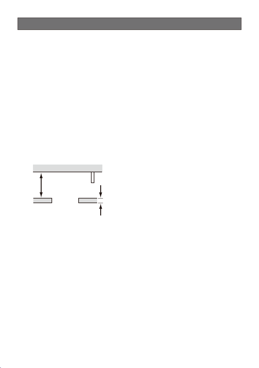
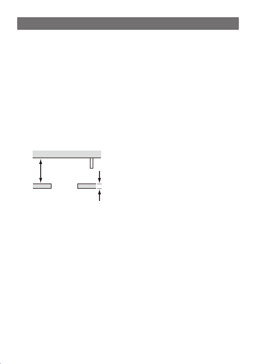
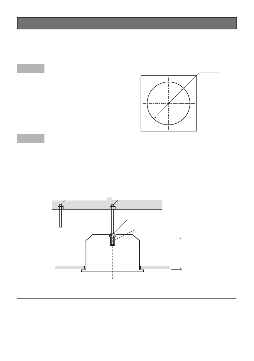
Installation area for this product
Make sure that the installation area is strong enough to hold the total weight of the camera •
assembly before installation.
The installation area shall have 210 mm {8-9/32 inches} or more space behind the ceiling.•
210 mm {8-9/32 inches}
or more
Ceiling board: between 9 mm {3/8 inches}
and 40 mm {1-9/16 inches}
The thickness of the ceiling board for installation can range between 9 mm {3/8 inches} and •
40 mm {1-9/16 inches}.
Do not place this product in the following places:
Locations where it may get wet from rain or water splash (including under the eaves, etc.)•
Locations where a chemical agent is used such as a swimming pool•
Locations subject to moisture or oil smoke such as a kitchen•
Locations that have a specific environment that is subject to an inflammable atmosphere or sol-•
vents
Locations where a radiation, an X-ray, a strong radio wave or a strong magnetic field is gener-•
ated
Locations where corrosive gas is produced, locations where it may be damaged by briny air such •
as seashores
Locations where the temperature is not within the specified range (–10 °C to +55 °C {14 °F to •
131 °F})
Locations subject to vibrations, such as on vehicles, marine vessels, or above product lines (This •
product is not designed for onvehicle use.)
Locations subject to condensation as the result of severe changes in temperature•
Page 5

5
Mounting method for this product
This product is designed to be used as a pendant mount camera. If the product is mounted on a
desktop or at a slant, it may not work correctly and its lifetime may be shortened.
Procure anchor bolts separately.
An anchor bolt for mounting the bracket on a ceiling is not supplied with the ceiling mount bracket.
Prepare them according to the material and strength of the area where the product is to be
installed.
Anchor bolt: M10, recommended•
Minimum pull-out strength: • Make sure that more than 5 times of the total weight including the
camera body can be supported.
Screw tightening
The screws and bolts must be tightened with an appropriate tightening torque according to the •
material and strength of the installation area.
Do not use an impact driver. Use of an impact driver may damage the screws or cause tightening •
excessively.
When a screw is tightened, make the screw at a right angle to the surface. After tightening the •
screws or bolts, perform checks to ensure that the tightening is sufficient enough so that there is
no movement or looseness.
Make sure to remove this product if it will no longer be used.
Page 6
6
Major Operating Controls
Mounting chassis
Camera mounting
stage
Paper gauge
<Installation sample>
Tie wrap (for cable installation)
(x4)
Ceiling board fixing screw (x4)
Ceiling board fixing bracket (x4)
Decorative cover (main)
Decorative cover (sub)
Roof space
Safety wire angle (accessory)
Safety wire (accessory)
Ceiling mount bracket
Ceiling board
Camera
Decorative cover
Page 7
7
Installations
Be sure to read "Precautions" (☞ page 3) and "Precautions for installation" (☞ page 4) before installation. Read the operating instructions for the camera to be installed as well.
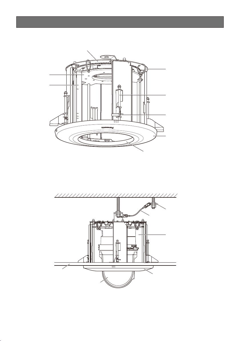
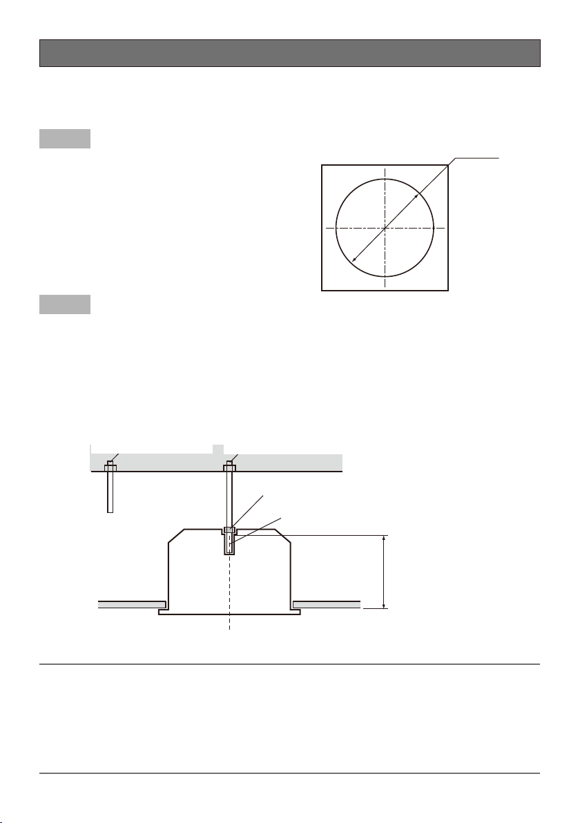
Step 1
Put Template A (accessory) against the ceiling and
make the ø220 mm {8-21/32 inches} hole.
Ceiling face
ø220 mm
{8-21/32 inches}
Step 2
Template A
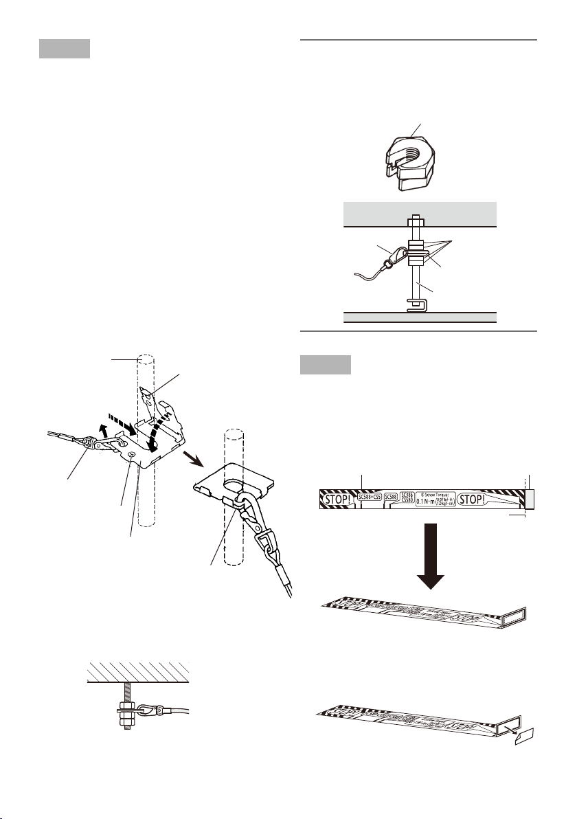
Install two anchor bolts (M10 recommended) into the ceiling.
One anchor is used for securing the mounting chassis, and the other anchor is used for connecting
the safety wire.
Determine the anchor bolt q (for securing the mounting chassis) length by use of Template B
(accessory).
Position the nut by use of Template B (accessory) w and mount the nut. (The distance between the
bottom surfaces of the ceiling board and nut shall be 183 mm {7-7/32 inches}.)
Anchor bolt (for connecting
the safety wire)
Template B
Ceiling board
Anchor bolt (for securing
the mounting chassis)
w Mount a nut
q Determine the anchor bolt length
183 mm {7-7/32 inches}
Install the anchor bolt in the center of the hole
Important:
The pull-out strength of the anchor bolt shall be more than 5 times of the total weight of the •
installed devices (including the camera body, ceiling mount bracket, anchor bolts, and all other
parts).
When the existing anchor bolt is used as an anchor bolt for connecting the safety wire, make •
sure that the distance between the anchor bolt and camera mounting position is 1 m {3.28 feet}
or less.
Page 8
8
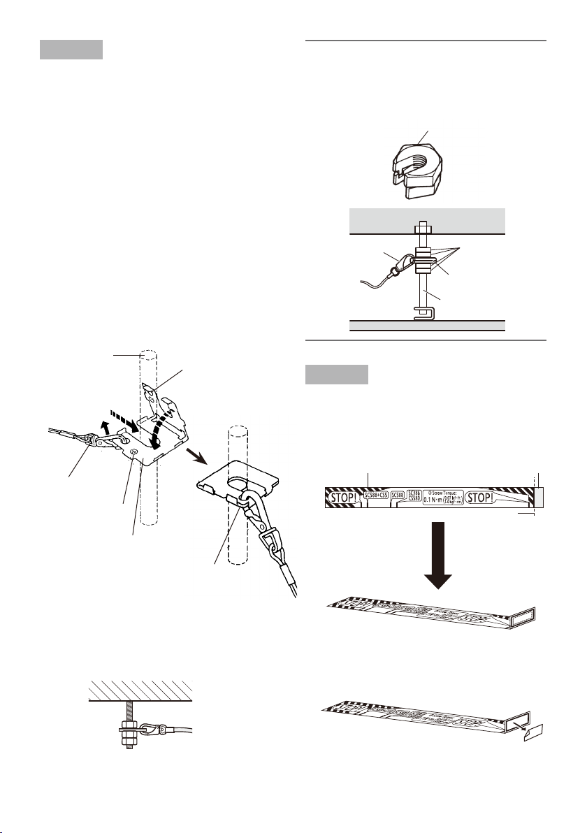
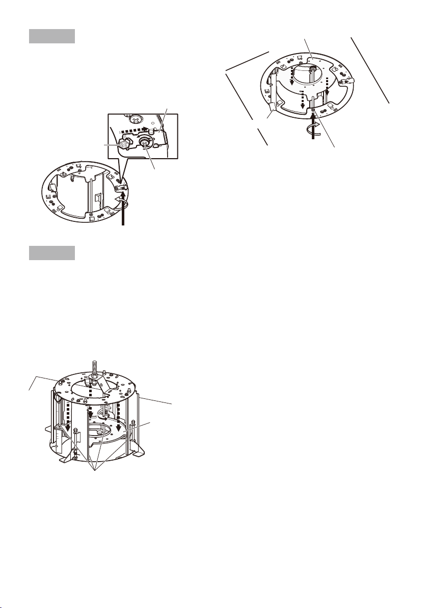
Step 3
Secure the safety wire angle (accessory) to the
anchor bolt (for connecting the safety wire),
and connect the safety wire (accessory).
Mount a nut so that the safety wire angle is q
secured on the anchor bolt.
Disconnect the safety wire from the safety w
wire angle.
Engage the face marked e q with the anchor
bolt.
Bend the face marked r w.
Connect the safety wire to the safety wire t
angle again.
Engage the nut from beneath, and secure y
the safety wire angle with top and bottom
nuts.
Engage another nut from beneath to tighten u
and secure the nut that was engaged from
beneath in y in a double nut fashion.
Note:
When the existing anchor bolt that has been •
installed is used for connecting the safety
wire, the use of 2 spacer nuts is helpful.
Safety wire
Spacer nuts
Spacer nuts
Safety wire angle
Existing anchor bolt
Anchor bolt
e Insert
w Disconnect
Safety wire
Mark q
Safety wire angle
Upper side
Mark w
r Bend
Lower
side
t Connect
* The nut is omitted in the illustration above.
<Image of safety wire connection>
Step 4
Attach the paper gauge (accessory) to the
camera mounting stage.
Fold the double-sided tape side of the q
paper gauge at a right angle as shown in
the drawing.
Paper gauge
Double-sided tape
Folding line
Peel off the backing from the double-sided w
tape of the paper gauge.
Page 9
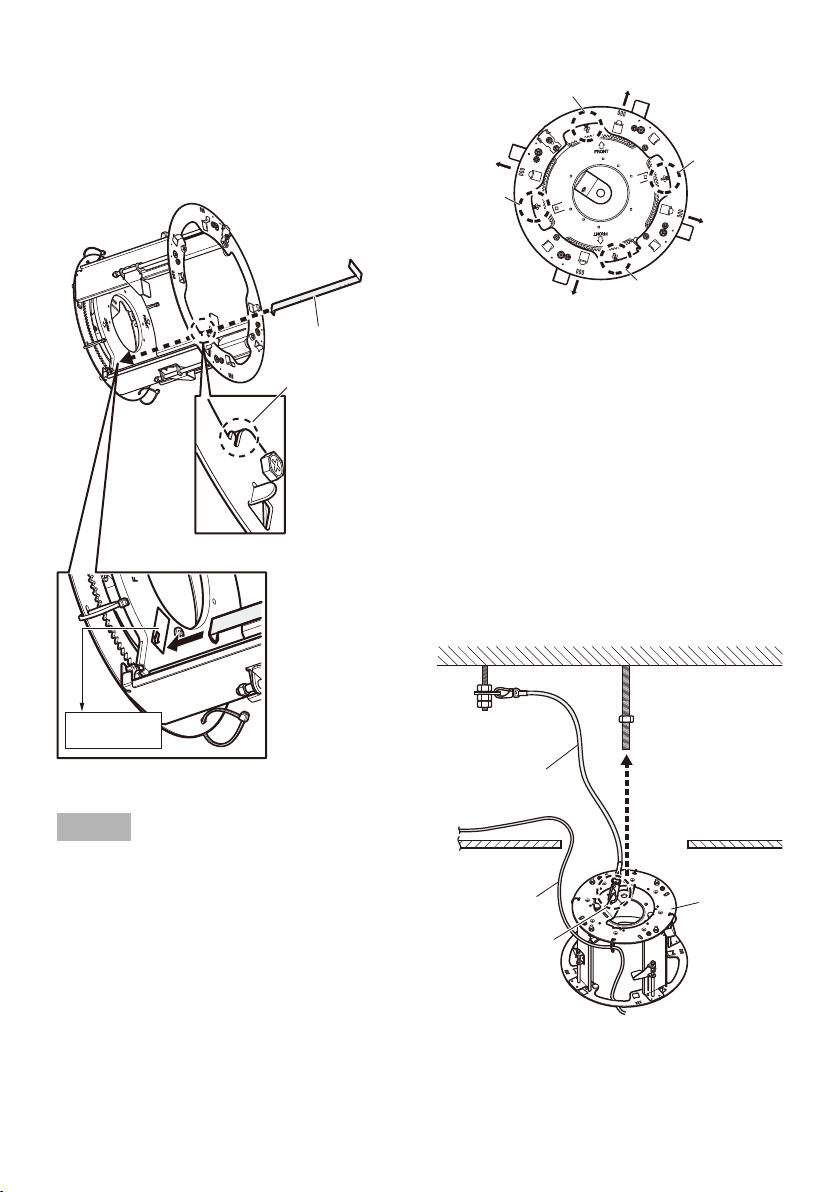
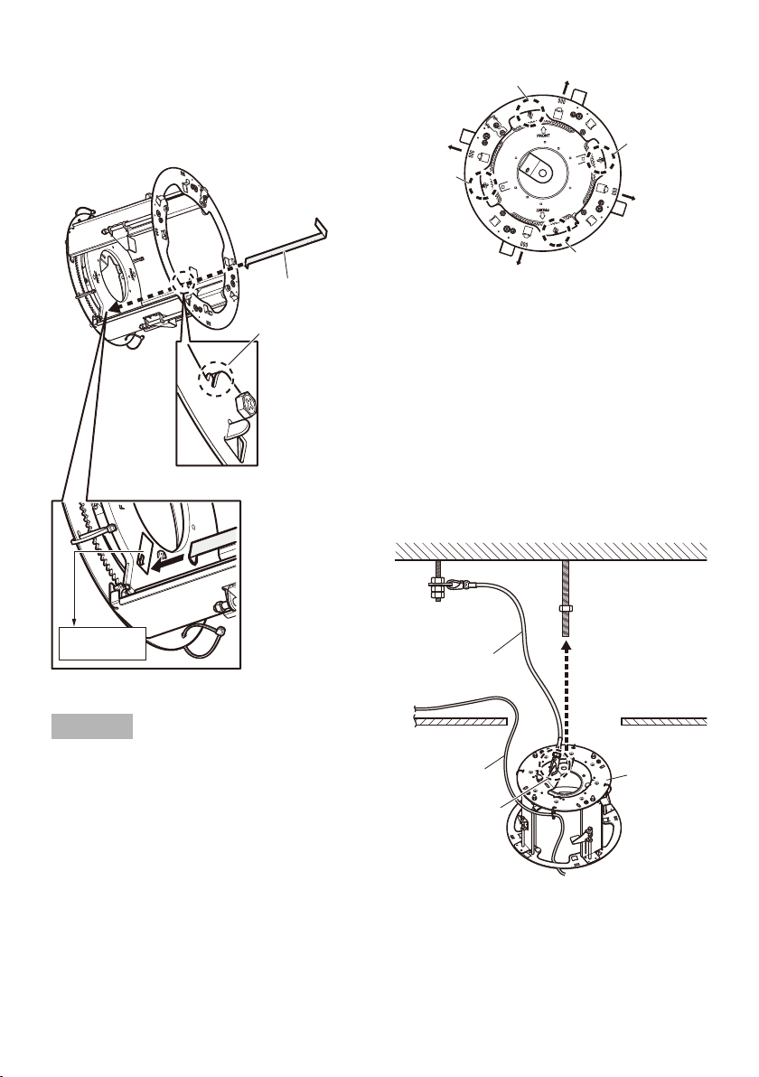
9
Turn this bracket sideways as shown in the e
following drawing, and attach the paper
gauge to the camera mounting stage.
Attach the paper gauge so that it passes
through the slit shown in the following drawing.
Direction of
brand logo
Tie wrap D
Tie wrap A
Direction of brand logo
Tie wrap B
Direction of
brand logo
Paper gauge
Slit
Paper gauge attaching position
b Attach the
paper gauge
Step 5
Pass the cables from the ceiling through the q
loop of the tie wrap attached to the mount
bracket in advance. Tie wraps used for
passing the cables vary with models. The
cable passing position is in the following
drawing.
Models with use of camera mount bracket
(accessory to the camera): tie wrap A or tie
wrap C in the following drawing
Models with use of base unit (component
of the camera): tie wrap B or tie wrap D in
the following drawing
Direction of
brand logo
Tie wrap C
Attach the safety wire to the mounting w
chassis as shown in the following drawing.
Insert the mounting chassis into the hole
made in Step 1, and put them into the roof
space.
At this moment, the logo direction at
mounting the decorative cover finally can
be aligned with the III direction of the
mounting chassis.
Therefore, if you care about the brand logo
direction, determine the direction using the
III direction.
Roof space
Safety wire
(accessory)
Ceiling board
Cables
Pass the loop
through the tip of
the safety wire.
Mounting
chassis
Page 10
10
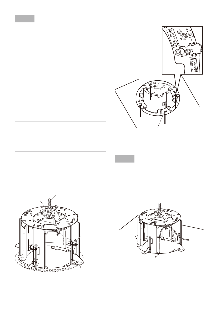
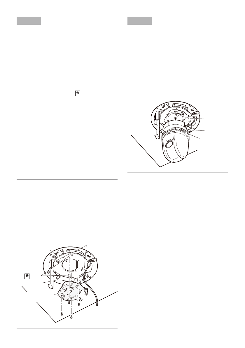
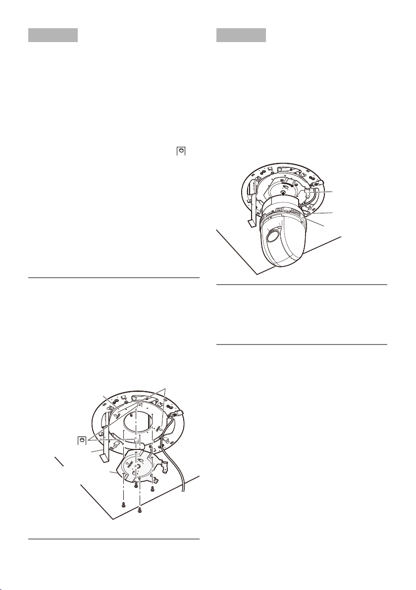
Step 6
Secure the mounting chassis to the ceiling
board with the ceiling board fixing screws (4
positions, screws with label q).
Engage the top of the mounting chassis q
with the anchor bolt (for securing the
mounting chassis).
Secure the mounting chassis by turning the w
ceiling board fixing screws clockwise when
viewing it from beneath. Turning the ceiling
board fixing screws clockwise provides ceiling board tightening between the bottom of
the mounting chassis and ceiling board fixing bracket resulting in mounting chassis
securing.
Recommended tightening torque:
0.78 N·m {0.58 lbf·ft}
Important:
When securing the mounting chassis on •
the ceiling, make sure that the 4 ceiling
board fixing brackets are open as shown in
the figure e.
<Installation image in a room>
Ceiling board fixing screw (x4)
(mounting chassis outside)
Recommended tightening torque:
0.78 N·m {0.58 lbf·ft}
Secure the top of the mounting chassis e
with double nuts.
<Image of roof space>
Double nuts
Anchor bolt (for securing the
mounting chassis)
Ceiling board
fixing screw
(x4)
Ceiling board fixing
bracket (x4)
Step 7
Prepare the cables.
Run the cables from the space of the mounting
chassis. The wiring image with the bracket
mounted on the ceiling is described below. Be
careful to prevent the cables from being caught
on the ceiling board fixing bracket or others.
Page 11
11
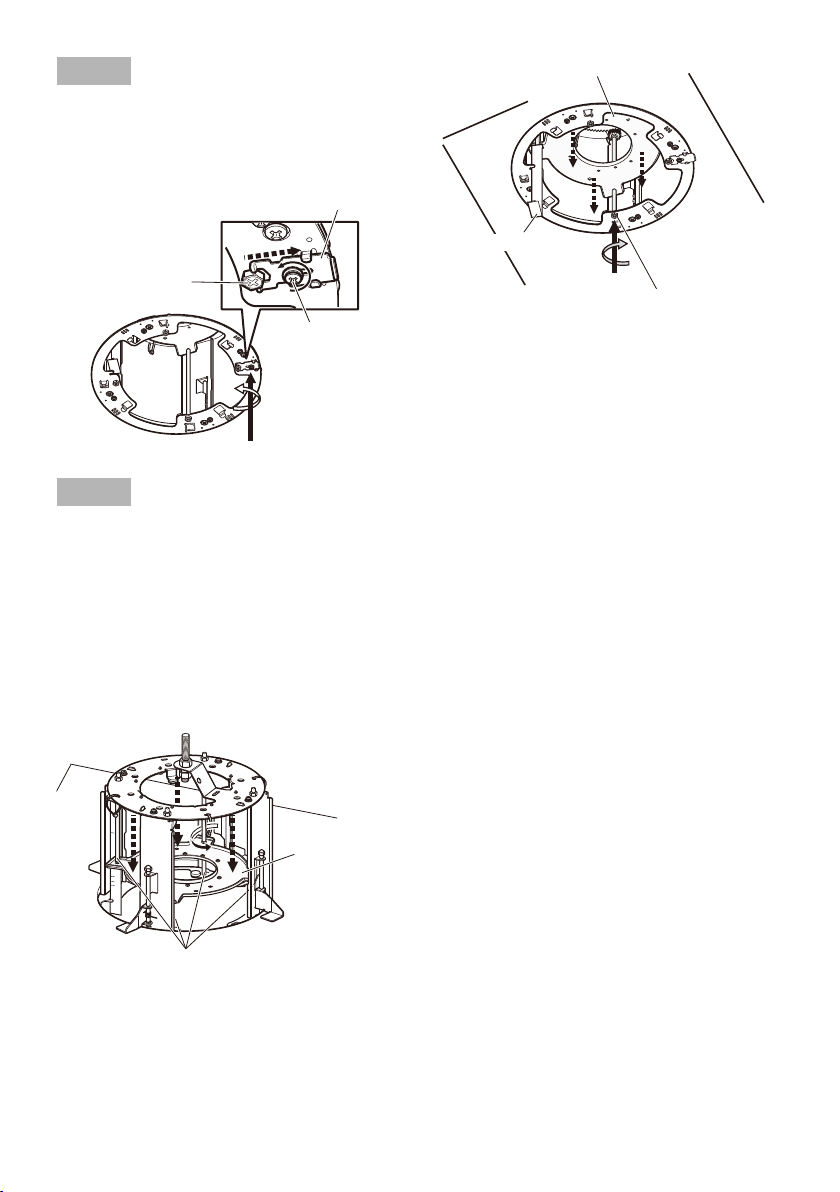
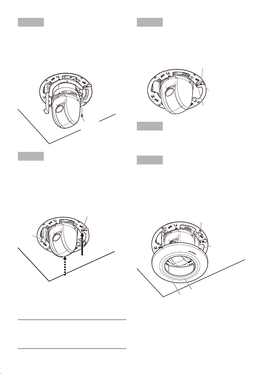
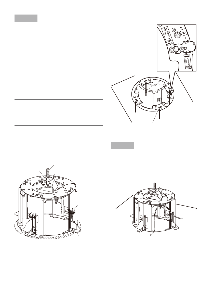
Step 8
Loosen the stopper bracket fixing screw, slide
the stopper bracket toward the outside of this
bracket (in the unlock w direction of the label),
and unlock the height adjusting screw.
Stopper bracket
Height adjusting
screw
Stopper bracket
fixing screw
Step 9
Rotate the height adjusting screw (one of 4
points) clockwise when viewing it from beneath
(in the e down direction of the label), and
move the camera mounting stage from the
back to the front side. At this moment, the
paper gauge attached to the camera mounting
stage descends together. Be careful to prevent
the cables from being caught between the
mounting chassis and camera mounting stage.
Camera mounting stage
Paper gauge
Height adjusting screw (mounting
chassis inside)
Adjustment can be performed with
the height adjusting screw at 1 point.
Tightening torque: 0.1 N·m {0.07 lbf·ft}
* Do not apply equal to or more than 0.29 N·m
{0.21 lbf·ft} of torque. Failure to observe this
may cause damage.
Camera mounting
stage
Height adjusting screw
Page 12
12
Step 10
Mount the camera mount bracket (accessory
to the camera) or base unit (component of the
camera) on the camera mounting stage.
When the camera mount bracket is used:
Align the gFRONT mark of the camera
mount bracket with the gFRONT mark at
the side where the cables are not passed
of the camera mounting stage.
When the base unit is used:
Align the direction that the cables of the
base unit exit with the
mark at the side
where the cables of the camera mounting
stage are passed.
Use M4 screws (accessories) to secure the
camera mount bracket or base unit at 4 points.
(Recommended tightening torque: 1.57 N·m
{1.16 lbf·ft})
Lay the cables between the mounting chassis
and camera mounting stage, and leave the
cables hanging down.
When the base unit is mounted, connect the
cables from the ceiling to the cables from the
base unit.
Note:
The selection between the base unit and •
camera mount bracket depends on the
camera type.
The base unit is a component of the cam-
era, and the camera mount bracket is an
accessory to the camera.
The camera mount bracket is attached in •
figures shown in the following descriptions.
Camera mounting
stage
gFRONT mark
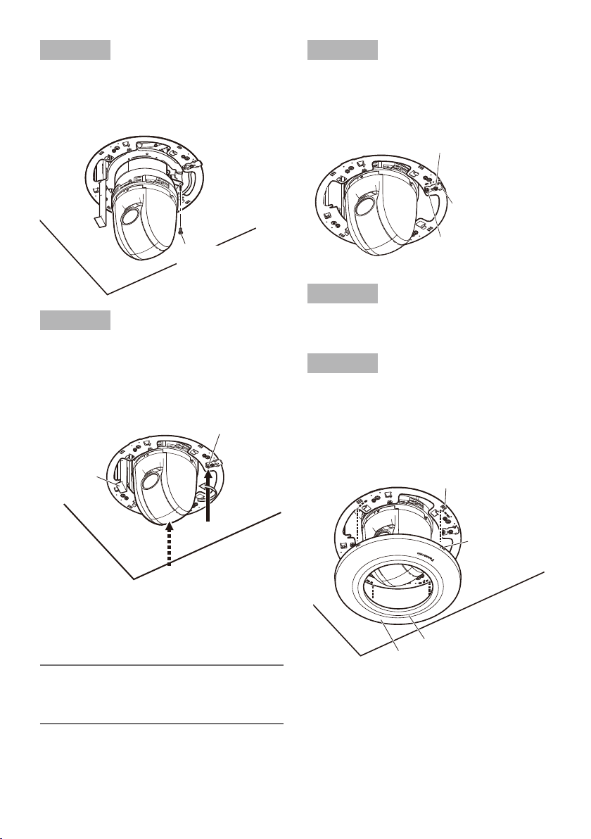
Step 11
Connect the cables to the camera, engage the
camera with the camera mount bracket so that
the bottom center of the camera is aligned with
the center of the camera mount bracket as
shown in the drawing below, align the lock
plate with the guide, and rotate the camera
clockwise by approx. 20 degrees when viewing
it from beneath to temporarily secure the camera.
* Refer to the installation guide of the camera
for details on how to install the camera.
Guide
Lock plate
Base part of the
camera
Important:
Do not let the cables be caught during •
installation work.
Be sure to mount it with holding the base •
part of the camera. Mounting the camera
while holding the dome part may result in
malfunction.
mark
Paper gauge
Camera mount
bracket
Screws (M4) x4 (accessory)
Page 13
13
Step 12
Secure the camera body to the camera mount
bracket (supplied with the camera) using a
piece of the camera fixing screw (M3, supplied
with the camera).
(Recommended tightening torque: 0.68 N·m
{0.50 lbf·ft})
Step 14
Push the stopper bracket (in the lock r direction of the label), and lock the height adjusting
screw. Secure the stopper bracket with the
stopper bracket fixing screw.
Stopper bracket
fixing screw
Stopper bracket
Height adjusting
screw
Camera fixing screw
(M3, supplied with
the camera)
Step 13
Rotate the height adjusting screw (one of 4
points) counterclockwise (in the e up direction
of the label) when viewing it from beneath, and
raise the camera mounting stage to the position of the model number in use displayed on
the paper gauge.
Height adjusting
screw
Paper
gauge
Tightening torque: 0.1 N·m {0.07 lbf·ft}
* Do not apply equal to or more than 0.29 N·m
{0.21 lbf·ft} of torque. Failure to observe this
may cause damage.
Step 15
Remove the protective sheet from the camera
lens.
Step 16
Align the III mark of the decorative cover supplied with this bracket with the III mark of the
mounting chassis, press the decorative cover
against the ceiling, and rotate the decorative
cover clockwise when viewing it from beneath
to secure the cover.
III mark of mounting
chassis
III mark of
decorative cover
Decorative cover (sub)
Decorative cover (main)
Note:
After adjusting the camera height, remove •
the paper gauge from this bracket, and discard it.
Page 14
14
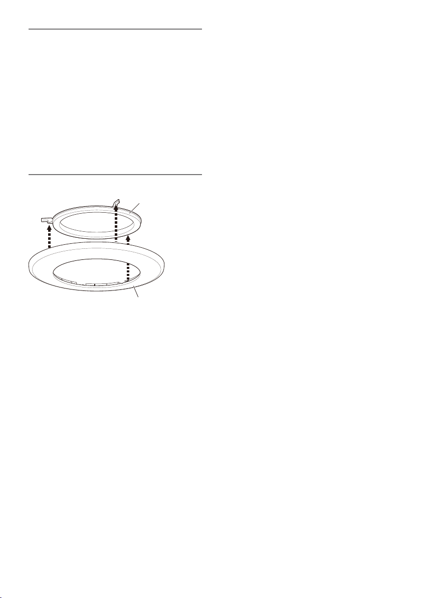
Note:
When the camera is embedded into the •
ceiling with use of this bracket, the decorative cover supplied with the camera is not
used.
When this bracket is installed with the WV- •
CS5S/WV-CS5C (dome cover) mounted on
WV-SC588 (network camera), remove the
decorative cover (sub) from the decorative
cover (main).
For other cases, use this bracket with the •
decorative cover (sub) being attached to
the decorative cover (main).
Decorative cover (sub)
Decorative cover (main)
Page 15

15
Specifications
Ambient operating temperature: –10 °C to +55 °C {14 °F to 131 °F}
Dimensions: ø245 mm x 203 mm (H) {ø9-21/32 inches x 8 inches (H)}
(including the decorative cover)
Mass: Approx. 1.3 kg {2.87 lbs}
Finish: Main body: Surface treatment steel sheet
Decorative cover: ABS resin (resin color: sail white, silver)
Standard accessories
Operating Instructions (this document) .........................................1 set
The following are for installation
Safety wire ...................................................................................1 pc.
Safety wire angle .........................................................................1 pc.
Template A ..............................................................................1 sheet
Template B ..............................................................................1 sheet
Decorative covers (sub and main), sail white, silver ........1 pc. for each
Screw (M4) .......................................................... 5 pcs. (incl. 1 spare)
Paper gauge ............................................................................ 1 sheet
Page 16

16
Inhalt
Features ....................................................................................................................................... 17
Vorsichtsmaßregeln ..................................................................................................................... 17
Vorsichtshinweise zur Installation ................................................................................................18
Wichtige Bedienungselemente .................................................................................................... 20
Installationsarbeiten ....................................................................................................................21
Technische Daten ........................................................................................................................29
Standardzubehör ......................................................................................................................... 29
Page 17

17
Features
Die Deckenmontagehalterung ist speziell für die
Montage dere Kamera an der Decke bestimmt.
Einzelheiten über dazu passende Kameramodelle finden Sie im Katalog oder in der
Bedienungsanleitung.
Vorsichtsmaßregeln
Zur Installation an einen Fachhändler wenden.
Installationsarbeiten erfordern Fachkenntnisse
und Erfahrung.
Andernfalls besteht die Gefahr von Brand, elektrischem Schlag, Verletzungen oder Schäden
an diesem Produkt.
Unbedingt einen Fachhändler konsultieren.
Die Halterung nicht in Bereichen installieren, wo sie Beschädigung durch Salz oder
korrosive Gase ausgesetzt ist.
Andernfalls können die Montageteile korrodieren, was zu Unfällen wie Herunterfallen des
Produkts führen kann.
Schrauben und Bolzen müssen auf das
vorgeschriebene Anzugsmoment festgezogen werden.
Lockere Bolzen oder Schrauben können zum
Herunterfallen des Produkts führen und dabei
Verletzungen oder Unfälle verursachen.
Diese Halterung nur in Verbindung mit den
dazu passenden Kameras verwenden
Andernfalls besteht die Gefahr des
Herunterfallens, was zu Körperverletzungen
führen kann.
Eine Einbaustelle wählen, die stark genug
ist, um das Gesamtgewicht zu tragen.
Wird eine ungeeignete Einbaustelle gewählt, so
kann das Produkt herunterfallen oder umstürzen, was zu Verletzungen oder Unfällen führen
kann.
Die Einbaustelle vor der Installation ausreichend
verstärken.
Die Kanten von Metallteilen möglichst
nicht mit der Hand berühren.
Anstoßen kann zu Verletzungen führen.
Die Halterung kann auch auf Flächen mit geringer Ausreißfestigkeit wie z.B. Gipsplatten in
einer abgehängten Decke verwendet werden.
Mit dieser Halterung wird die Kamera in die
Decke eingelassen, womit sich der freiliegende
Teil des Gehäuses reduziert.
Regelmäßige Kontrollen müssen durchgeführt werden.
Bei Verwendung von rostigen Metallteilen oder
Schrauben kann das Produkt herunterfallen
und dabei Verletzungen oder Unfälle verursachen.
Kontrollen durch Fachhändler durchführen lassen.
Es sind Maßnahmen gegen das
Herunterfallen des Produkts zu treffen.
Andernfalls besteht die Gefahr des Herunterfallens, was zu Körperverletzungen oder
Unfällen führen kann.
Unbedingt den Fangdraht anbringen.
Nur die speziell für das Produkt bestimmte
Montagehalterung verwenden.
Andernfalls besteht die Gefahr des Herunterfallens, was zu Körperverletzungen oder
Unfällen führen kann.
Zur Installation die speziell für das Produkt
bestimmte Montagehalterung verwenden.
Das Produkt nicht an Orten installieren,
wo es Vibration ausgesetzt ist.
Lockere Bolzen oder Schrauben können zum
Herunterfallen des Produkts führen und dabei
Verletzungen oder Unfälle verursachen.
Das Produkt keinen Schlägen oder starken Erschütterungen aussetzen.
Andernfalls besteht die Gefahr von Körperverletzungen oder Brand.
Das Produkt hoch genug installieren,
damit man sich den Kopf nicht daran
stößt.
Andernfalls kann es zu Verletzungen kommen.
Nicht am Produkt hangeln oder es als
Trittbrett benutzen.
Andernfalls besteht die Gefahr des Herunterfallens, was zu Unfällen führen kann.
DEUTSCH
Page 18
18
Vorsichtshinweise zur Installation
Panasonic übernimmt keine Verantwortung für Verletzungen oder Sachschäden, die aus
der Installation oder Bedienung resultieren, die nicht wie in dieser Dokumentation
beschrieben ausgeführt werden.
Die Installationsarbeiten müssen den örtlichen elektrotechnischen Vorschriften entsprechen.
Das Produkt ist für den Einsatz in Innenräumen bestimmt.
Das Produkt ist nicht für den Einsatz im Freien bestimmt.
Das Produkt nicht an Orten installieren, wo es längere Zeit direkter Sonneneinstrahlung ausgesetzt
ist, oder in der Nähe einer Heizung oder Klimaanlage.
Andernfalls kann es zu Verformungen, Verfärbungen oder Störungen kommen. Das Produkt vor
Wasser und Feuchtigkeit schützen.
Einbaufläche für das Produkt
Vor dem Einbau sicherstellen, dass die Einbaufläche ausreichend fest ist, um das Gesamtgewicht •
der Kamerabaugruppe zu tragen.
Hinter der Einbaufläche muss mindestens 210 mm Freiraum vorhanden sein.•
210 mm oder mehr
Deckenplatte: zwischen 9 mm und 40 mm
Die Dicke der Deckenplatte, in die das Produkt eingebaut wird, darf zwischen 9 mm und 40 mm •
betragen.
Folgende Standorte sind zu vermeiden:
Orte, die Regen oder Sprühwasser ausgesetzt sind (auch unter einem Dachvorsprung)•
Orte, die chemischen Stoffen ausgesetzt sind, z.B. in der Nähe eines Schwimmbads•
Orte, wo Feuchtigkeit und ölige Dünste auftreten, z.B. eine Küche•
Orte, wo die Luft leicht entflammbare Gase oder Lösungsmittel enthält•
Orte, wo Strahlung, Röntgenstrahlen, starke elektromagnetische Wellen oder Magnetfelder •
erzeugt werden
Orte, wo korrosives Gas erzeugt wird oder Schäden durch salzhaltige Luft entstehen könnten, •
z.B. in Küstennähe
Orte, wo die Temperatur nicht im vorgeschriebenen Bereich (–10 °C bis +55 °C ) liegt.•
Vibration ausgesetzte Orte wie z.B. an Bord eines Fahrzeugs oder Schiffs oder oberhalb einer •
Produktionsstraße (Das Produkt ist nicht für den Betrieb an Bord eines Fahrzeugs bestimmt.)
Orte, wo aufgrund starker Temperaturschwankungen Kondensation auftritt•
Montage des Produkts
Das Produkt ist für den Einsatz als Hängekamera bestimmt. Montage des Produkts auf einem Tisch
oder auf einer Schrägfläche kann zu Funktionsstörungen oder vorzeitigem Altern führen.
Page 19

19
Ankerschrauben bitte getrennt zu beschaffen.
Ankerschrauben für die Montage der Halterung an der Decke gehören nicht zum Lieferumfang.
Die Befestigungsmittel müssen für das Material und die Stärke der Montagefläche des Produkts
geeignet sein.
Ankerschraube: M10, empfohlen•
Mindestausreißfestigkeit: Sicherstellen, dass die Montage mindestens das Fünffache des •
Kameragewichts tragen kann.
Festziehen der Schrauben
Schrauben und Bolzen müssen mit dem für das Material und die Stärke der Einbaufläche geeig-•
neten Anzugsmoment festgezogen werden.
Keinen Schlagschrauber verwenden. Durch Schlagschrauber könnten die Schrauben beschä-•
digt oder zu fest angezogen werden.
Zum Festziehen muss die Schraube im rechten Winkel zur Montagefläche stehen. Nach dem •
Anziehen der Schrauben bzw. Bolzen durch Kontrollen sicherstellen, dass alle ausreichend fest
angezogen sind und keine wackeln oder locker sitzen.
Bei Nichtgebrauch sollte das Produkt unbedingt ausgebaut werden.
Page 20

20
Wichtige Bedienungselemente
Einbaurahmen
Kamera-
Montagegestell
Messstreifen
<Montagebeispiel>
Kabelbinder (für Verkabelung)
(x4)
DeckenplattenBefestigungsschraube (x4)
Deckenplattenhalterung (x4)
Abdeckblende (Haupt)
Abdeckblende (Zusatz)
Deckenplatte
Kamera
Deckenzwischenraum
Fangdraht-Haltewinkel (Zubehör)
Fangdraht (Zubehör)
Deckenmontagehalterung
Abdeckblende
Page 21
21
Installationsarbeiten
Vor dem Einbau unbedingt die Abschnitte "Vorsichtsmaßregeln" (☞ Seite 17) und "Vorsichtshinweise
zur Installation" (☞ Seite 18) lesen. Auch die Bedienungsanleitung der zu montierenden Kamera
lesen.
Schritt 1
Schablone A (Zubehör) ab die Decke halten und
Deckenfläche
ø220 mm
einen ø220 mm Durchbruch anbringen.
Schritt 2
Schablone A
Zwei Ankerschrauben (M10 empfohlen) in die Decke einbauen.
Eine der Ankerschrauben dient zum Sichern des Einbaurahmens, die andere zum Befestigen des
Fangdrahts.
Mithilfe der Schablone B (Zubehör) die Länge der Ankerschraube (zum Sichern des Einbaurahmens) q
festlegen.
Die Mutter mithilfe der Schablone B (Zubehör) in die richtige Lage bringen. (Der Abstand zwi- w
schen der Unterfläche der Deckenplatte und der Mutter muss 183 mm betragen.)
Ankerschraube
(zum Befestigen des Fangdrahts)
Ankerschraube
(zum Befestigen des Einbaurahmens)
w Mutter aufschrauben
q Die Länge der Ankerschraube festlegen
Schablone B
Deckenplatte
Die Ankerschraube mittig in die Bohrung einschrauben
183 mm
WICHTIG:
Die Ausreißfestigkeit der Ankerschraube muss mindestens dem Fünffachen des insgesamt mon-•
tierten Gewichts (einschließlich Kameragehäuse, Deckenmontagehalterung, Ankerschrauben
und sonstige Teile) entsprechen.
Bei Verwendung einer vorhandenen Ankerschraube zum Befestigen des Fangdrahts darauf ach-•
ten, dass der Abstand zwischen der Ankerschraube und der montierten Kamera höchstens 1 m
betragen darf.
Page 22
22
Schritt 3
Den Fangdraht-Haltewinkel (Zubehör) an der
Ankerschraube (zum Befestigen des Fangdrahts) anbringen und den Fangdraht (Zubehör)
daran befestigen.
Den Fangdraht-Haltewinkel mit einer Mutter q
an der Ankerschraube sichern.
Den Fangdraht vom Fangdraht-Haltewinkel w
trennen.
Die mit e q markierte Fläche auf die Anker-
schraube setzen.
Die mit r w markierte Fläche runterbiegen.
Den Fangdraht wieder am Fangdraht- t
Haltewinkel befestigen.
Die Mutter von unten her einsetzen und den y
Fangdraht-Haltewinkel oben und unten mit
je einer Mutter sichern.
Zur Sicherung der von unten aufgeschraub- u
ten Mutter eine weitere Mutter aufschrauben, so dass sich die mit y bezeichnete
Doppelmuttersicherung ergibt.
Anmerkung:
Bei Anschluss des Fangdrahts an eine •
bereits vorhandene Ankerschraube können
zum Höhenausgleich zwei Distanzmuttern
verwendet werden.
Fangdraht
Distanzmuttern
Fangdraht-Haltewinkel
Vorhandene
Ankerschraube
Distanzmuttern
Ankerschraube
e Einsetzen
w Trennen
Fangdraht
Markierung q
Fangdraht-Haltewinkel
Oben
Markierung w
r Umbiegen
Unten
t Anschließen
* In der obigen Abbildung sind die Muttern
weggelassen.
<Anschluss des Fangdrahts>
Schritt 4
Den Messstreifen (Zubehör) am KameraMontagegestell befestigen.
Das als doppelseitiges Klebeband ausge- q
bildete Ende des Messstreifens wie abgebildet rechtwinklig umfalten.
Messstreifen
Doppelseitiges Klebeband
Faltlinie
Die Schutzfolie vom doppelseitigen w
Klebeband am Messstreifen abziehen.
Page 23
23
Die Montagehalterung wie unten abgebildet e
auf die Seite drehen und den Messstreifen
am Kamera-Montagegestell befestigen.
Den Messstreifen so befestigen, dass er in
dem in der folgenden Abbildung gezeigten
Schlitz sitzt.
LogoRichtung
Kabelbinder D
Kabelbinder A
Logo-Richtung
Kabelbinder B
LogoRichtung
Messstreifen
Schlitz
Befestigungsstelle für Messstreifen
b Attach the
paper gauge
Schritt 5
Vorher die Kabel aus der Decke durch die q
Schlaufe einer der an der Montagehalterung
vorhandenen Kabelbinder führen. Je nach
Modell wird ein anderer Kabelbinder für die
Sicherung der Kabel verwendet. Die
Durchführungsposition ist aus folgender
Abbildung ersichtlich.
Modelle mit Kamera-Montagehalterung
(Zubehör zur Kamera): Kabelbinder A oder
Kabelbinder C in der folgenden Abbildung
Modelle mit Kamera-Grundplatte (Teil der
Kamera): Kabelbinder B oder Kabelbinder
D in der folgenden Abbildung
Logo-Richtung
Kabelbinder C
Den Fangdraht wie abgebildet am Einbau- w
rahmen befestigen. Den Einbaurahmen
durch den in Schritt 1 angebrachten
Durchbruch in den Deckenzwischenraum
einsetzen.
Beim Anbringen der Abdeckblende kann
das Logo so ausgerichtet werden, dass es
mit der auf dem Einbaurahmen angegebenen Richtung III übereinstimmt.
Soll das Logo ausgerichtet werden, so
kann dies anhand der Markierung III erfolgen.
Deckenzwischenraum
Fangdraht (Zubehör)
Deckenplatte
Kabel
Das Ende des
Fangdrahts
durch die Öse
führen.
Einbau rahmen
Page 24
24
Schritt 6
Den Einbaurahmen mit den DeckenplattenBefestigungsschrauben (4 Stellen, Schrauben
markiert q) an der Deckenplatte montieren.
Die Oberseite des Einbaurahmens auf die q
Ankerschraube (zum Sichern des
Einbaurahmens) setzen.
Den Einbaurahmen durch Drehen der w
Deckenplatten-Befestigungsschrauben im
Uhrzeigersinn (von unten gesehen) montieren. Durch das Festziehen der Deckenplatten-Befestigungsschrauben im Uhrzeigersinn wird die Unterseite des Einbaurahmens an die Deckenplattenhalterungen
gepresst und gesichert.
Empfohlenes Anzugsmoment: 0,78 N·m
WICHTIG:
Beim Befestigen des Einbaurahmens an •
der Decke sicherstellen, dass die 4
Deckenplattenhalterungen offen sind, wie in
Abbildung e gezeigt.
Den Einbaurahmen oben mit zwei Muttern e
sichern.
<Deckenzwischenraum>
Ankerschraube (zum Befestigen
des Einbaurahmens)
Zwei Muttern
<Einbau in den Deckenzwischenraum>
Deckenplatten-Befestigungsschraube (x4)
(Einbaurahmen außen)
Empfohlenes Anzugsmoment: 0,78 N·m
Schritt 7
Die Kabel vorbereiten.
Die Kabel durch den Einbaurahmen führen. Die
Abbildung unten zeigt die Verkabelung bei
montierter Halterung. Darauf achten, dass sich
die Kabel nicht in den Deckenplattenhalterungen
oder anderen Teilen verfangen.
DeckenplattenBefestigungsschraube (x4)
Deckenplattenhalterung
(x4)
Page 25
25
Schritt 8
Die Befestigungsschraube des Verschlussblechs lockern, das Verschlussblech zum
Außenrand der Montagehalterung schieben (in
Entriegelungsrichtung w) und die Höhenverstellschrauben lösen.
Verschlussblech
Kamera-Montagegestell
Messstreifen
Höhenverstellschraube
VerschlussblechBefestigungsschraube
Schritt 9
Die Höhenverstellschraube (eine der 4
Schrauben) von unten gesehen im Uhrzeigersinn drehen (in Richtung e) und das
Kamera-Montagegestell von hinten nach vorne
schieben. Dabei wird der am KameraMontagegestell angebrachte Messstreifen mitbewegt. Darauf achten, dass die Kabel nicht
zwischen Einbaurahmen und KameraMontagegestell eingeklemmt werden.
KameraMontagegestell
Höhenverstellschraube
(Montagegestellseite)
Die Einstellung kann durch
Verstellen einer der
Höhenverstellschrauben
vorgenommen werden.
Anzugsmoment: 0,1 N·m
* Das Anzugsmoment darf 0,29 N·m nicht
überschreiten. Andernfalls kann es zu
Beschädigungen kommen.
Höhenverstellschraube
Page 26
26
Schritt 10
Die Kamera-Montagehalterung (Zubehör zur
Kamera) oder die Grundplatte (Teil der Kamera)
am Kamera-Montagegestell montieren.
Bei Verwendung der Kamera-Montagehalterung:
Die Markierung gFRONT an der Kamera-
Montagehalterung auf die Markierung
gFRONT auf der kabelfreien Seite des
Kamera-Montagegestells ausrichten.
Bei Verwendung der Grundplatte:
Die Seite der Grundplatte, aus der die
Kabel austreten, auf die Markierung
auf
der Austrittseite der Kabel aus dem
Kamera-Montagegestell ausrichten.
Die Kamera-Montagehalterung bzw. die Grundplatte an 4 Stellen mit M4-Schrauben (Zubehör)
sichern.
(Empfohlenes Anzugsmoment: 1,57 N·m)
Die Kabel zwischen Einbaurahmen und
Kamera-Montagegestell verlegen und die
Enden herunter hängen lassen.
Bei Verwendung der Grundplatte die aus der
Decke kommenden Kabel mit den aus der
Grundplatte austretenden Kabeln verbinden.
Schritt 11
Die Kabel an die Kamera anschließen und die
Kamera so in die Kamera-Montagehalterung
einsetzen, dass die Mitte der KameraUnterseite wie abgebildet auf die Mitte der
Kamera-Montagehalterung ausgerichtet ist.
Das Sicherungsblech auf die Führung ausrichten und die Kamera im Uhrzeigersinn (von
unten gesehen) ca. 20 Grad drehen, um sie
provisorisch zu sichern.
* Zu Einzelheiten über die Installation der
Kamera siehe das dieser beiliegende
Installationshandbuch.
Führung
Sicherungsblech
Kamera-Basis
Anmerkung:
Die Wahl zwischen Grundplatte und •
Kamera-Montagehalterung hängt vom
Kameramodell ab.
Die Grundplatte ist Teil der Kamera, wäh-
rend die Kamera-Montagehalterung als
Zubehör zur Kamera geliefert wird.
Die folgenden Abbildungen zeigen die •
Montage mit der Kamera-Montagehalterung.
Kamera-Montagegestell
Markierung
Messstreifen
Montagehalterung
Kamera-
Markierung gFRONT
Schrauben (M4) x4
(Zubehör)
WICHTIG:
Bei den Arbeiten darauf achten, das die •
Kabel nicht eingeklemmt werden.
Die Kamera bei der Montage an der Basis •
greifen. Halten der Kamera am Dome kann
zu Funktionsstörungen führen.
Page 27
27
Schritt 12
Das Kameragehäuse mit einer KameraBefestigungsschraube (M3, der Kamera beiliegend) an der Kamera-Montagehalterung (der
Kamera beiliegend) sichern.
(Empfohlenes Anzugsmoment: 0,68 N·m)
Schritt 14
Durch Verschieben des Verschlussblechs (in
Richtung r zum Verriegeln) die Höhenverstellschraube sichern. Das Verschlussblech mit
der Befestigungsschraube sichern.
VerschlussblechBefestigungsschraube
Verschlussblech
KameraBefestigungsschraube
(M3, der Kamera
beiliegend)
Schritt 13
Eine der Höhenverstellschrauben (eine von 4)
von unten gesehen gegen den Uhrzeigersinn
drehen (in Richtung e) und das KameraMontagegestell auf die Höhe anheben, die für
das jeweilige Kameramodell auf dem Messstreifen angegeben ist.
Höhenverstellschraube
Messstreifen
Anzugsmoment: 0,1 N·m
* Das Anzugsmoment darf 0,29 N·m nicht
überschreiten. Andernfalls kann es zu
Beschädigungen kommen.
Anmerkung:
Nach der Einstellung der Kamerahöhe den •
Messstreifen auf der Halterung ziehen und
entsorgen.
Höhenverstellschraube
Schritt 15
Die Schutzfolie vom Objektiv der Kamera abziehen.
Schritt 16
Die Markierung III an der der Halterung beiliegenden Abdeckblende auf die Markierung III
am Einbaurahmen ausrichten, die Abdeckblende an die Decke drücken und durch
Drehen im Uhrzeigersinn (von unten gesehen)
sichern.
Markierung III am
Einbaurahmen
Markierung III an
der Abdeckblende
Abdeckblende (Zusatz)
Abdeckblende (Haupt)
Page 28

28
Anmerkung:
Wenn die Kamera mit der Montagehalterung •
in die Decke eingelassen wird, entfällt die
mit der Kamera gelieferte Abdeckblende.
Bei Verwendung der Montagehalterung in •
Verbindung mit WV-CS5S/WV-CS5C
(Dome-Abdeckung) und WV-SC588 (Netzwerkkamera) muss die Abdeckblende
(Zusatz) von der Abdeckblende (Haupt) entfernt werden.
In allen anderen Fällen wird die Abdeck-•
blende (Zusatz) mit der Abdeckblende
(Haupt) verwendet.
Abdeckblende (Zusatz)
Abdeckblende (Haupt)
Page 29

29
Technische Daten
Betriebsumgebungstemperatur: –10 °C bis +55 °C
Abmessungen: ø245 mm x 203 mm (H) (einschl. Abdeckblende)
Masse: Ca. 1,3 kg
Finish: Gehäuse: Stahlblech, oberflächenbehandelt
Abdeckblende: ABS-Kunststoff (Farbe: segelweiß, silberfarben)
Standardzubehör
Bedienungsanleitung (vorliegendes Dokument) .......................................... 1 Satz
Montagezubehör
Fangdraht ...................................................................................................... 1 St.
Fangdraht-Haltewinkel ................................................................................... 1 St.
Schablone A ............................................................................................... 1 Blatt
Schablone B ............................................................................................... 1 Blatt
Abdeckblenden (Zusatz- und Hauptblende), segelweiß, silberfarben ...........je 1 St.
Schraube (M4) ............................................................................ 5 St. (1 Reserve)
Messstreifen ............................................................................................... 1 Blatt
Page 30

30
Table des matières
Caractéristiques dominantes ......................................................................................................30
Mesures de précaution ................................................................................................................ 31
Précautions d’installation ............................................................................................................ 32
Principaux organes de commande .............................................................................................34
Installations .................................................................................................................................35
Caractéristiques techniques ........................................................................................................ 43
Accessoires standard .................................................................................................................. 43
Caractéristiques dominantes
Cette potence de fixation au plafond est exclusivement conçue pour installer la caméra vidéo
sur un plafond. Pour obtenir de plus amples
informations sur les modèles compatibles, se
référer au catalogue ou au manuel d'utilisation
de la caméra vidéo.
Cette platine de fixation d'installation peut être
utilisée pour une installation sur une surface
possédant une faible résistance à la traction
telle qu'une plaque de plâtre dans un double
plafond.
Cette platine de fixation d'installation est un
type encastré destiné à réduire la partie exposée du boîtier de caméra vidéo.
Page 31

31
Mesures de précaution
Confier les travaux d'installation au distributeur.
Les travaux d’installation exigent des connaissances techniques et de l’expérience.
Le fait de ne pas observer ceci peut engendrer
un incendie, provoquer une décharge électrique, des blessures voire endommager ce produit.
Faire en sorte de consulter le distributeur.
Éviter d’installer cette platine de fixation
d’installation dans des emplacements où
des dégâts par le sel se produisent ou du
gaz corrosif est produit.
Dans le cas contraire, les parties servant à
l’installation se détérioreront et des accidents
tels qu’une chute de ce produit peuvent se
produire.
Les vis et les boulons doivent être serrés
au couple indiqué.
Un desserrage des vis de fixation ou des boulons peut engendrer une chute du produit et
ceci peut occasionner des blessures ou provoquer des accidents.
Ne pas utiliser cette platine de fixation
d'installation excepté avec les caméras
vidéo appropriées.
Le fait de ne pas respecter cette recommandation risque d’entraîner une chute capable de
blesser quelqu’un.
Sélectionner un secteur d’installation
capable de supporter le poids total.
Le fait de sélectionner une surface inadéquate
pour l’installation peut provoquer la chute de
ce produit ou qu’il se renverse, ceci ayant pour
résultat de blesser quelqu’un ou engendres de
accidents.
Les travaux d’installation ne doivent commencer qu’après le renforcement suffisant de la
surface d’accueil.
Des inspections périodiques doivent être
effectuées.
Une formation de rouille sur les parties métalliques ou sur les vis peut engendrer une chute
du produit ou provoquer des accidents.
Se mettre en rapport avec le distributeur en ce
qui concerne les inspections à faire.
Les mesures de protection nécessaires
contre toute chute de ce produit doivent
être prises.
Le fait de ne pas respecter cette recommandation risque d’entraîner une chute capable de
blesser quelqu’un ou provoquer des accidents.
Ne pas oublier d’installer le câble de sécurité.
La platine de fixation d’installation exclusivement conçue doit être utilisée.
Le fait de ne pas respecter cette recommandation risque d’entraîner une chute capable de
blesser quelqu’un ou provoquer des accidents.
Utiliser la platine de fixation d’installation exclusivement conçue pour l’installation.
Ne pas installer le produit dans des
emplacements soumis à des vibrations.
Un desserrage des vis de fixation ou des boulons peut engendrer une chute du produit et
ceci peut occasionner des blessures ou provoquer des accidents.
Ne pas frapper ni soumettre ce produit à
des chocs violents.
Le fait de ne pas respecter cette précaution risque d’aboutir à des blessures voire de créer un
incendie.
Installer ce produit dans un endroit suffisamment élevé pour éviter que des personnes et des objets se cognent ou se
butent dans le produit.
Le fait de ne pas respecter cette précaution risque d’aboutir à des blessures.
FRANÇAIS
Ne jamais frotter le bord des parties
métalliques à mains nues.
Le fait de frotter vigoureusement peut provoquer des blessures.
Ne pas se suspendre à partir de ce produit
ni utiliser ce produit comme piédestal.
Le fait de ne pas respecter cette recommandation risque d’engendrer la chute de l’appareil et
de résulter par des accidents.
Page 32

32
Précautions d’installation
Panasonic n’assume aucune responsabilité en cas de dommages corporels ou matériels
résultant de pannes dues à une installation incorrecte ou à une utilisation contraire à ce
qui est indiqué dans cette documentation.
L’installation doit être conforme au code électrique local.
Ce produit est conçu pour être installé à l’intérieur.
Ce produit ne peut pas pour mis en service à l’extérieur.
Ce produit ne doit pas être exposé directement au soleil pendant des heures ni ne doit être installé
près d’un appareil de chauffage ou d’un système d’air conditionné.
Sinon, cela risque de provoquer une déformation, une décoloration voire une panne. Conserver ce
produit loin de l’eau et de l’humidité.
Secteur d’installation pour ce produit
Il convient de s'assurer que la surface d'installation est suffisamment robuste pour supporter le •
poids total de l'ensemble de caméra vidéo avant de procéder à l'installation.
Le secteur d'installation doit pouvoir aménager 210 mm {8-9/32 pouces} ou davantage d'es-•
pace derrière le plafond.
210 mm {8-9/32 pouces}
ou plus.
Panneau de plafond: entre 9 mm {3/8 pouces} et
40 mm {1-9/16 pouces}
L'épaisseur du panneau de plafond sélectionné pour faire l'installation peut se situer dans les •
limites de 9 à 40 mm {3/8 pouces à 1-9/16 pouces}.
Ne pas placer ce produit dans les emplacements suivants:
Emplacements où il risque d’être mouillé par la pluie ou par des éclaboussures d’eau (sous des •
gouttières y compris, etc.)
Emplacements ou un agent chimique est utilisé comme dans le cas d'une piscine•
Emplacements en présence d’humidité ou d’émanations d’huile comme dans le cas d’une cui-•
sine
Emplacements situés dans un environnement particulier pouvant être exposé à une atmosphère •
où il existe des produits inflammables ou des solvants
Emplacements où un rayonnement, des rayons X, des puissantes ondes radio ou un champ •
magnétique intense est produit
Emplacements où du gaz corrosif est produit, emplacements où il peut être endommagé par de •
l’air saumâtre tel qu’en bord de mer
Emplacements où la température ne se trouve pas dans les limites de la gamme spécifiée •
(–10 °C à +55 °C {14 °F à 131 °F}).
Emplacements sujets aux vibrations, comme dans le cas d’une installation sur des véhicules, •
des navires maritimes ou au-dessus de chaînes de production (ce produit n’est pas conçu être
utilisé en mode d’installation sur véhicule.)
Emplacements soumis à une condensation résultant d’importants changements de tempéra-•
ture
Page 33

33
Méthode d’installation pour ce produit
Ce produit est conçu pour être utilisé comme une caméra vidéo à installation en position suspendue. Si le produit est installé sur un bureau ou en position inclinée, il risque de ne pas fonctionner
correctement et sa durée de vie utile de service risque d’être écourtée.
Se procurer les boulons d'ancrage séparément.
Un boulon d'ancrage servant à l'installation de la platine de fixation d'installation sur un plafond
n'est pas fourni avec la platine de fixation d'installation au plafond.
Se les procurer en fonction des matériaux et de la résistance de la surface appelée à accueillir le
produit.
Boulon d'ancrage: M10, recommandé•
Capacité de dégagement minimum exigée: S'assurer que plus de 5 fois le poids total compre-•
nant le boîtier de la caméra vidéo peuvent être supportés.
Serrage de vis
Les vis de fixation et les boulons d’installation doivent être serrés au couple de serrage approprié •
en fonction des matériaux et de la résistance de la surface appelée à accueillir le produit.
Ne pas se servir d’un tournevis à percussion à impact. L’utilisation d’un tournevis à percussion •
risque d’endommager les vis ou d’engendrer un serrage excessif.
Quand une vis est serrée, faire en sorte que la vis se trouve à angle droit par rapport à la surface. •
Dès que le serrage des vis de fixation ou des boulons est terminé, procéder à des vérifications
afin de s’assurer que le serrage est suffisant de telle sorte qu’il n’y ait aucun mouvement ou jeu
des éléments installés.
Faire en sorte de retirer sans faute ce produit s’il n’est plus utilisé.
Page 34

34
Principaux organes de commande
Châssis d'installation
Plate-forme
d'installation de
caméra vidéo
Jauge en papier
<Exemple d'installation>
Espace de toit
Attache à tête d'équerre (pour
installation de câble) (4)
Vis de fixation de panneau de
plafond (4)
Platine de fixation de panneau
de plafond (4)
Couvercle décoratif
(principal)
Couvercle décoratif
(secondaire)
Cornière de câble de sécurité
(accessoire)
Câble de sécurité (accessoire)
Panneau de plafond
Potence de fixation au plafond
Couvercle décoratif
Caméra vidéo
Page 35

35
Installations
Faire en sorte de lire les "Mesures de précaution" (☞ page 31) et les "Mesures de précaution pour
l'installation" (☞ page 32) avant de procéder à l'installation. Lire également le manuel d'utilisation de
la caméra vidéo à installer.
Étape 1
Placer le gabarit A (accessoire) contre la surface au
plafond et percer une ouverture de ø220 mm
Surface du plafond
ø220 mm
{8-21/32 pouces}
{8-21/32 pouces}.
Gabarit A
Étape 2
Fixer deux boulons d'ancrage (M10 recommandé) dans le plafond.
Un ancrage est utilisé pour fixer le châssis d'installation et l'autre ancrage est utilisé pour connecter
le câble de sécurité.
Déterminer la longueur du boulon d'ancrage (servant à la fixation du châssis d'installation) en q
utilisant le gabarit B (accessoire).
Placer l'écrou au moyen du gabarit B (accessoire) et monter l'écrou. (La distance entre les sur- w
faces de base du panneau de plafond et l'écrou de fixation doit être de 183 mm {7-7/32 pouces}.)
Boulon d'ancrage (pour
raccorder le câble de sécurité)
Boulon d'ancrage (pour raccorder le
châssis d'installation)
w Monter un écrou
q Déterminer la longueur du boulon d'ancrage
Gabarit B
Panneau de
plafond
Fixer un boulon d'ancrage au centre de l'ouverture
183 mm {7-7/32 pouces}
IMPORTANT:
La résistance à la traction du boulon d'ancrage devrait être supérieure de plus de 5 fois le poids •
total des appareils installés (ceci comprenant le boîtier de caméra vidéo, la potence de fixation
au plafond, les boulons d'ancrage et toutes autres pièces utilisées).
Quand le boulon d'ancrage existant est utilisé comme boulon d'ancrage pour connecter le câble •
de sécurité, s'assurer que la distance entre le boulon d'ancrage et la position de fixation de la
caméra vidéo est de 1 m {3,28 feet} ou moins.
Page 36

36
Étape 3
Fixer la cornière du câble de sécurité (accessoire) au boulon d'ancrage (servant au raccordement du câble de sécurité) et raccorder le
câble de sécurité (accessoire).
Fixer un écrou de telle sorte que la cornière q
du câble de sécurité soit solidement fixée
sur le boulon d'ancrage.
Débrancher le câble de sécurité de la cor- w
nière de câble de sécurité.
Engager la surface identifiée par e q sur le
boulon d'ancrage.
Replier la surface identifiée par r w.
Raccorder à nouveau le câble de sécurité à t
la cornière du câble de sécurité.
Engager l'écrou en procédant par en des- y
sous, puis fixer solidement la cornière de
câble de sécurité avec les écrous du haut et
du bas.
Engager un autre écrou en procédant par u
en dessous pour serrer et fixer l'écrou qui a
été engagé par en dessous dans y suivant
un double mode de fixation d'écrou.
Remarque:
Quand le boulon d'ancrage existant qui a •
été installé est utilisé pour raccorder le câble
de sécurité, l'utilisation de 2 écrous à entretoise est utile.
Câble de
sécurité
Écrous d'entretoise
Écrous
d'entretoise
Cornière de câble de
sécurité
Boulon d'ancrage déjà
en place
Boulon
d'ancrage
e Introduire
w Débrancher
Câble de sécurité
Repère q
Cornière de câble
de sécurité
Côté supérieur
Repère w
r Plier
Côté inférieur
t Connecter
* L'écrou de fixation n'est pas représenté dans
l'illustration ci-dessus.
<Image de raccordement de câble de
sécurité>
Étape 4
Fixer la jauge en papier (accessoire) sur la
plate-forme d'installation de caméra vidéo.
Replier le côté de la bande adhésive recto- q
verso de la jauge en papier suivant un angle
droit comme représenté sur le schéma.
Jauge en papier
Bande adhésive recto-verso
Ligne de pliage
Décoller le dos de la bande adhésive recto- w
verso de la jauge en papier.
Page 37

37
Faire tourner cette platine de fixation sur le e
côté suivant les indications du schéma cidessous, puis attacher la jauge en papier à
la plate-forme d'installation de caméra
vidéo. Fixer la jauge en papier de telle sorte
qu'elle passe dans la fente comme représenté sur le schéma ci-dessous.
Jauge en papier
Fente
Position de fixation de jauge en papier
Sens d'orientation du
Attache à tête d'équerre A
Sens
d'orientation
du logo de
marque
Attache
à tête
d'équerre
D
Sens d'orientation
du logo de
marque
logo de marque
Attache à tête
d'équerre B
Attache à tête
d'équerre C
Sens
d'orientation
du logo de
marque
Attacher le câble de sécurité au châssis w
d'installation suivant les indications du
schéma ci-dessous. Insérer le châssis
d'installation dans l'ouverture percée au
cours de l'étape 1, puis les placer dans
l'espace du toit.
À ce moment, l'orientation du logo pour
l'installation du couvercle extérieur peut
finalement être alignée avec l'orientation III
du châssis d'installation.
Par conséquent, si vous vous inquiétez à
propos de l'orientation du logo de marque,
déterminer l'orientation en utilisant l'orientation III.
b Attach the
paper gauge
Étape 5
Faire passer les câbles du plafond par la q
boucle de l'attache à tête d'équerre fixée à
la platine de fixation d'installation à l'avance.
Les attaches à tête d'équerre utilisées pour
faire passer les câbles varient selon les
modèles. La position d'engagement de
câble est comme représentée sur le schéma
ci-dessous.
Modèles avec une utilisation de la platine
de fixation d'installation de caméra vidéo
(accessoire à la caméra vidéo): Attache à
tête d'équerre A ou attache à tête
d'équerre C dans le schéma suivant
Modèles avec une utilisation de l'unité de
base (composant de la caméra vidéo):
Attache à tête d'équerre B ou attache à
tête d'équerre D dans le schéma suivant
Câble de sécurité
(accessoire)
Câbles
Faire passer la
boucle dans
l'extrémité du
câble de
sécurité.
Espace de toit
Panneau de
plafond
Châssis
d'installation
Page 38

38
Étape 6
Fixer solidement le châssis d'installation au
panneau de plafond avec les vis de fixation de
panneau de plafond (4 endroits, vis de fixation
portant l'étiquette q).
Engager le haut du châssis d'installation sur q
le boulon d'ancrage (pour fixer le châssis
d'installation).
Fixer le châssis d'installation en tournant les w
vis de fixation de panneau de plafond dans
le sens des aiguilles d'une montre en le
visualisant du dessous. Le fait de tourner
les vis de fixation de panneau de plafond
dans le sens des aiguilles d'une montre a
pour effet de serrer le panneau de plafond
entre le châssis d'installation et la platine de
fixation de panneau de plafond, ce qui offre
une fixation robuste du châssis d'installation.
Couple de serrage recommandé: 0,78 N·m
{0,58 lbf·ft}
<Image d'installation dans une pièce>
IMPORTANT:
Lorsque le châssis d'installation est fixé au •
plafond, il convient de s'assurer que les
quatre platines de fixation de panneau de
plafond sont ouvertes comme cela est
représenté sur la figure e.
Fixer le haut du châssis d'installation avec e
de doubles écrous.
<Image de l'espace de toit>
Boulon d'ancrage (pour raccorder
le châssis d'installation)
Double écrous de
fixation
Vis de
fixation de
panneau de
plafond (4)
Platine de fixation
de panneau de
plafond (4)
Vis de fixation de panneau de
plafond (4)
(extérieur de châssis d'installation)
Couple de serrage recommandé:
0,78 N·m {0,58 lbf·ft}
Étape 7
Préparer les câbles.
Acheminer les câbles à partir de l'espace du
châssis d'installation. L'image de câblage avec
la platine de fixation d'installation montée sur
plafond est décrite ci-dessous. Prendre toutes
les précautions nécessaires pour que les
câbles ne soient pas pris par la platine de fixation de panneau de plafond ou par d'autres
éléments.
Page 39

39
Étape 8
Desserrer la vis de fixation de platine de fixation
de butée, faire coulisser la platine de fixation de
butée vers l'extérieur de cette platine de fixation (dans le sens du déverrouillage w de l'étiquette), puis déverrouiller la vis de réglage de
hauteur.
Platine de fixation de butée
Plate-forme d'installation de
caméra vidéo
Jauge en papier
Vis de réglage de
hauteur
Vis de fixation de
platine de fixation de
butée
Étape 9
Faire tourner la vis de réglage de hauteur (une
des 4 endroits) dans le sens des aiguilles d'une
montre en la visualisant à partir du dessous
(vers le bas e de l'étiquette), puis déplacer la
plate-forme d'installation de caméra vidéo à
nouveau de la partie antérieure vers l'avant. À
ce moment-là, la jauge en papier attachée à la
plate-forme d'installation de caméra vidéo descend ensemble. Faire attention à ce que les
câbles ne soient pas pris entre le châssis d'installation et la plate-forme d'installation de
caméra vidéo.
Vis de réglage de hauteur
(intérieur de châssis d'installation)
Le réglage peut être exécuté avec
la vis de réglage de hauteur à 1
emplacement.
Couple de serrage: 0,1 N·m {0,07 lbf·ft}
* Ne pas appliquer un couple de valeur égale à
0,29 N·m {0,21 lbf·ft} ou davantage. Le fait de
ne pas respecter cette précaution risque
d'endommager des éléments.
Plate-forme
d'installation de
caméra vidéo
Vis de réglage de hauteur
Page 40

40
Étape 10
Installer la platine de fixation d'installation de
caméra vidéo (accessoire à la caméra vidéo) ou
l'unité de base (composant de la caméra vidéo)
sur la plate-forme d'installation de caméra
vidéo.
Lorsque la platine de fixation d'installation de
caméra vidéo est utilisée:
Aligner le repère gFRONT de la platine de
fixation d'installation de caméra vidéo avec
le repère gFRONT se trouvant du côté où
les câbles ne sont pas passés de la plateforme d'installation de caméra vidéo.
Quand l'unité de base est utilisée:
Aligner le sens par lequel les câbles de
l'unité de base avec le repère
se trouvant du côté où les câbles sont passés de
la plate-forme d'installation de caméra
vidéo.
Utiliser les vis M4 (accessoires) pour fixer la
platine de fixation d'installation de caméra
vidéo ou l'unité de base à 4 endroits.
(Couple de serrage recommandé: 1,57 N·m
{1,16 lbf·ft})
Acheminer les câbles entre le châssis d'installation et la plate-forme d'installation de caméra
vidéo et laisser les câbles pendre.
Quand l'unité de base est installée, connecter
les câbles à partir du plafond aux câbles provenant de l'unité de base.
Étape 11
Raccorder les câbles à la caméra vidéo, engager la caméra vidéo avec la platine de fixation
d'installation de telle sorte que le centre de la
partie inférieure de la caméra vidéo soit aligné
avec le centre de la platine de fixation d'installation de caméra vidéo comme représenté sur
le schéma ci-dessous, aligner la plaque de verrouillage avec le guide, puis faire tourner la
caméra vidéo dans le sens des aiguilles d'une
montre sur approximativement 20 degrés en la
visualisant à partir du dessous pour fixer provisoirement la caméra vidéo.
* Se référer au guide d'installation de la caméra
vidéo pour obtenir tous les détails sur la façon
dont on doit installer la caméra vidéo.
Guide
Plaque de
verrouillage
Partie de base de la
caméra vidéo
Remarque:
La sélection entre l'unité de base et la pla-•
tine de fixation d'installation de caméra
vidéo dépend du type de caméra vidéo.
L'unité de base est un composant de la
caméra vidéo et la platine de fixation d'installation de caméra vidéo est un accessoire
à la caméra vidéo.
La platine de fixation d'installation de •
caméra vidéo est attachée dans les figures
jointes dans les descriptions suivantes.
Plate-forme d'installation
de caméra vidéo
Repère
Jauge en
papier
Platine de fixation
d’installation de
caméra vidéo
Repère gFRONT
Vis de fixation (M4) x4
(accessoire)
IMPORTANT:
Ne pas laisser les câbles se faire prendre •
pendant les travaux d'installation.
S'assurer de l'installer tout saisissant la par-•
tie de base de la caméra vidéo. Une installation de la caméra vidéo tout en immobilisant la partie du dôme risque de se traduire
par des erreurs de fonctionnement.
Page 41

41
Étape 12
Bloquer le boîtier de caméra vidéo sur la platine
de fixation d'installation de caméra vidéo (fourni
avec la caméra vidéo) en utilisant une partie de
la vis de fixation de caméra vidéo (M3, fournie
avec la caméra vidéo).
(Couple de serrage recommandé: 0,68 N·m
{0,50 lbf·ft})
Vis de fixation de
caméra vidéo
(M3, fourni avec la
caméra vidéo)
Étape 13
Faire tourner la vis de réglage de hauteur (un
des 4 endroits) dans le sens inverse des
aiguilles d'une montre (e vers le haut de la
direction de l'étiquette) quand le visionnement
est fait dessous, puis relever la plate-forme
d'installation de caméra vidéo jusqu'à la position du numéro de modèle en service affiché
sur la jauge en papier.
Vis de réglage de hauteur
Jauge en
papier
Étape 14
Repousser la platine de fixation de butée (dans
le sens de verrouillage r de l'étiquette), et bloquer la vis de réglage de hauteur. Serrer fermement la platine de fixation de butée avec la vis
de fixation de platine de fixation de butée.
Vis de fixation de platine de
fixation de butée
Platine de fixation
de butée
Vis de réglage de
hauteur
Étape 15
Retirer le film de protection de l'objectif de
caméra vidéo.
Étape 16
Aligner le repère III du couvercle décoratif fourni
avec cette platine de fixation avec le repère III
du châssis d'installation, repousser le couvercle
décoratif contre le plafond, puis faire tourner le
couvercle décoratif dans le sens des aiguilles
d'une montre en le visualisant du dessous pour
fixer le couvercle.
Repère III de châssis
d'installation
Couple de serrage: 0,1 N·m {0,07 lbf·ft}
* Ne pas appliquer un couple de valeur égale à
0,29 N·m {0,21 lbf·ft} ou davantage. Le fait de
ne pas respecter cette précaution risque
d'endommager des éléments.
Remarque:
Après avoir faire le réglage de la hauteur de •
la caméra vidéo, retirer la jauge en papier
de cette platine de fixation et la jeter.
Repère III de
couvercle
décoratif
Couvercle décoratif
(secondaire)
Couvercle décoratif (principal)
Page 42

42
Remarque:
Quand la caméra vidéo est encastrée dans •
le plafond avec l'utilisation de cette platine
de fixation, le couvercle décoratif fourni
avec la caméra vidéo n'est pas utilisé.
Quand cette platine de fixation est installée •
avec le modèle WV-CS5S/WV-CS5C (couvercle en dôme) monté sur la caméra vidéo
WV-SC588 (caméra en réseau), retirer le
couvercle décoratif (secondaire) du couvercle décoratif (principal).
Dans les autres cas, utiliser cette platine de •
fixation avec le couvercle décoratif (secondaire) fixé au couvercle décoratif (principal).
Couvercle décoratif
(secondaire)
Couvercle décoratif
(principal)
Page 43

43
Caractéristiques techniques
Température ambiante en service: –10 °C à +55 °C {14 °F a 131 °F}
Dimensions: ø245 mm x 203 mm(H) {ø9-21/32 pouces x 8 pouces (H)}
Masse: Environ 1,3 kg {2,87 lbs}
Finition: Bloc principal: Tôle d'acier de traitement de surface
Couvercle décoratif: Résine ABS
(couleur résine: Blanc voile, argent)
(comprenant le couvercle décoratif)
extérieure
Accessoires standard
Manuel d'installation (le présent document)......................................................1 ensemble
Les éléments suivants sont utilisés pour effectuer l'installation
Câble de sécurité .......................................................................................................1 él.
Cornière de câble de sécurité ..................................................................................... 1 él.
Gabarit A ...............................................................................................................1 feuille
Gabarit B ............................................................................................................... 1 feuille
Couvercles décoratifs (secondaires et principal), blanc voile, argent ...........1 él. de chaque
Vis (M4) ...................................................5 él. (y compris une vis de fixation de rechange)
Jauge en papier .....................................................................................................1 feuille
Page 44

44
Índice
Características ............................................................................................................................ 45
Precauciones ............................................................................................................................... 45
Precauciones para la instalación ................................................................................................. 46
Principales controles de operación ............................................................................................. 48
Instalaciones ...............................................................................................................................49
Especificaciones ......................................................................................................................... 57
Accesorios estándar .................................................................................................................... 57
Page 45

45
Características
Esta ménsula de montaje en el techo está diseñada exclusivamente para montar la cámara en
el techo. Consulte el catálogo o el manual de
instrucciones de la cámara para encontrar más
información sobre los modelos compatibles.
Precauciones
Solicite el trabajo de instalación al distribuidor.
Es necesario poseer técnica y experiencia para
realizar el trabajo de instalación.
Si no lo hace así, pueden ocasionarse incendios, descargas eléctricas, heridas, o daños en
el producto.
Consúltelo sin falta al distribuidor.
No instale esta ménsula en lugares propicios a daños producidos por el salitre ni
en los que se produzcan gases corrosivos.
De lo contrario, se deteriorarían las partes de
montaje y podrían ocurrir accidentes tales
como la caída de este producto.
Los tornillos y los pernos deberán apretarse a la torsión especificada.
La flojedad de los tornillos o pernos de montaje
puede ocasionar la caída del producto y el
riesgo de sufrir heridas o accidentes.
No emplee esta ménsula si no es con las
cámaras adecuadas.
Si no lo hace así, puede producirse una caída
que presentará peligro de heridas.
Seleccione un lugar de instalación que
pueda soportar el peso total.
La selección de una superficie de instalación
inadecuada puede causar la caída o el desprendimiento de este producto, pudiendo ocasionar lesiones o accidentes.
El trabajo de instalación deberá comenzarse
después de haber reforzado suficientemente la
superficie.
No frote los bordes de las partes metálicas con las manos.
El frotamiento fuerte podría causar lesiones.
Esta ménsula puede utilizarse para un lugar
con poca resistencia de soporte, como pueda
ser una placa de yeso de un techo doble.
Esta ménsula es del tipo empotrado hace que
sea menor la parte visible del cuerpo de la
cámara.
Deberán llevarse a cabo inspecciones
periódicas.
La corrosión de las partes metálicas o de los
tornillos puede ocasionar la caída del producto
y el riesgo de sufrir heridas o accidentes.
Consulte a su distribuidor para las inspecciones.
Deberán tomarse medidas de protección
contra la caída de este producto.
Si no lo hace así, puede producirse una caída
que presentará peligro de heridas u otros accidentes.
Asegúrese de instalar el cable de seguridad.
Deberá utilizar la ménsula de montaje
exclusivamente diseñada.
Si no lo hace así, puede producirse una caída
que presentará peligro de heridas u otros accidentes.
Emplee la ménsula de montaje exclusivamente
diseñada para realizar la instalación.
No instale este producto en lugares sujetos a vibraciones.
La flojedad de los tornillos o pernos de montaje
puede ocasionar la caída del producto y el
riesgo de sufrir heridas o accidentes.
No golpee este producto y procure que no
reciba otros golpes fuertes.
Si no sigue esta indicación, correrá peligro de
incendios o heridas.
Instale este producto en un lugar lo suficientemente alto para que ninguna persona ni objeto puedan golpear el producto.
Si no sigue esta indicación, correrá peligro de
heridas.
ESPAÑOL
No se cuelgue de este producto ni emplee
el producto como un pedestal.
Si no lo hace así, puede producirse una caída
con peligro de accidentes.
Page 46

46
Precauciones para la instalación
Panasonic no se hace responsable de lesiones o daños a la propiedad que resulten de
fallos derivados de una incorrecta instalación o funcionamiento que no se ajuste con
esta documentación.
La instalación debe cumplir las regulaciones locales sobre electricidad.
Este producto ha sido diseñado para su utilización en interiores.
Este producto no puede funcionar al aire libre.
No exponga este producto a la luz directa del sol durante mucho tiempo y no lo instale cerca de
una estufa o acondicionador de aire.
De lo contrario, podría producirse deformación, decoloración y mal funcionamiento. Mantenga este
producto alejado del agua y de la humedad.
Área de instalación para este producto
Asegúrese de que el lugar de instalación sea suficientemente fuerte para poder soportar el peso •
total del conjunto de la cámara antes de realizar la instalación.
El lugar de instalación deberá tener un espacio de 210 mm o más detrás del techo.•
210 mm o más
Placa del techo: entre 9 mm y 40 mm
El espesor de la placa del techo para la instalación deberá ser de 9 mm a 40 mm.•
No ponga este producto en los lugares siguientes:
Lugares en los que pueda mojarse con la lluvia o agua salpicada (incluyendo la parte inferior de •
los aleros, etc.)
Lugares en los que se empleen productos químicos como en las piscinas•
Lugares sujetos a humedad o humo grasiento como en la cocina•
Lugares que tengan un entorno especial que estén sujetos a ambientes o solventes inflama-•
bles
Lugares donde se genere radiación, rayos X, ondas de radio potentes o campos magnéticos •
fuertes
Lugares en los que se produzca gas corrosivo, lugares en los que pueda dañarse debido al aire •
con salitre como en la costa del mar
Lugares en los que la temperatura no esté dentro del margen especificado (–10 °C a +55 °C ).•
Lugares sujetos a vibraciones, como pueda ser en el interior de vehículos, embarcaciones o •
encima de líneas de producción (Este producto no está diseñado para ser empleado dentro de
vehículos.)
Lugares sometidos a condensación de humedad resultante de fuertes cambios de temperatu-•
ras
Método de montaje para este producto
Este producto está diseñado para ser utilizado como una cámara de montaje colgado. Si el producto se monta en una mesa o inclinado, es posible que no funcione correctamente y que se
acorte su vida de servicio.
Page 47

47
Adquiera pernos de anclaje por separado.
El perno de anclaje para montar la ménsula en un techo no se suministra con la ménsula de montaje en el techo.
Prepárelos de acuerdo con el material y la resistencia del lugar donde deba instalarse el producto.
Perno de anclaje: M10, recomendado•
Resistencia mínima al tiro hacia fuera: Asegúrese de tener resistencia para poder soportar más •
de 5 veces el peso total incluyendo el cuerpo de la cámara.
Apriete de tornillos
Los tornillos y pernos deben apretarse a la torsión de apriete apropiada de acuerdo con el mate-•
rial y la resistencia del lugar de instalación.
No emplee un destornillador de impacto. El empleo de un destornillador de impacto puede •
causar daños en los tornillos o su apriete excesivo.
Cuando apriete un tornillo, póngalo en ángulo recto con respecto a la superficie. Después de •
haber apretado los tornillos o pernos, efectúe comprobaciones para asegurarse de que estén
suficientemente apretados de modo que no se produzca movimiento ni flojedad.
No se olvide de desmontar este producto si no se propone seguir utilizándolo.
Page 48

48
Principales controles de operación
Chasis de montaje
Plataforma de
montaje de la cámara
Calibrador de
papel
<Ejemplo de instalación>
Sujetador (para instalación de
los cables) (x4)
Tornillo de fijación de la placa
del techo (x4)
Ménsula de fijación de la placa
del techo (x4)
Cubierta decorativa
(principal)
Cubierta decorativa
(secundaria)
Placa del techo
Cámara
Espacio del
techo
Ménsula angular de cables de
seguridad (accesorio)
Cable de seguridad (accesorio)
Ménsula de montaje en el
techo
Cubierta decorativa
Page 49

49
Instalaciones
Asegúrese de leer las "Precauciones" (☞ página 45) y las "Precauciones para la instalación" (☞
página 46) antes de la instalación. Lea también el manual de instrucciones de la cámara que se
proponga instalar.
Paso 1
Ponga la plantilla A (accesoria) contra el techo y
haga un orificio de 220 mm de diámetro.
Superficie del techo
Plantilla A
220 mm de
diámetro
Paso 2
Instale dos pernos de anclaje (M10 recomendados) en el techo.
Un anclaje se empleará para fijar el chasis de montaje, y el otro anclaje se empleará para conectar
el cable de seguridad.
Determine la longitud del perno de anclaje (para fijar el chasis de montaje) empleando la plantilla q
B (accesoria).
Ubique la tuerca empleando la plantilla B (accesoria) e instale la tuerca. (La distancia entre las w
superficies inferiores de la placa del techo y de la tuerca deberá ser de 183 mm.)
Perno de anclaje (para conectar
el cable de seguridad)
Perno de anclaje (para fijar el chasis
de montaje)
w Monte una tuerca
q Determine la longitud del perno de anclaje
Plantilla B
Placa del
techo
Instale el perno de anclaje en el centro del orificio
183 mm
Importante:
La resistencia al tiro hacia fuera del perno de anclaje deberá ser de más de 5 veces el peso total •
de los dispositivos instalados (incluyendo el cuerpo de la cámara, la ménsula de montaje en el
techo, los pernos de anclaje y todos los demás accesorios).
Cuando emplee un perno de anclaje existente como perno de anclaje para conectar el cable de •
seguridad, asegúrese de que la distancia entre el perno de anclaje y la posición de montaje de
la cámara sea de 1 m o menos.
Page 50

50
Paso 3
Fije la ménsula angular de cables de seguridad
(accesoria) en el perno de anclaje (para conectar el cable de seguridad) y conecte el cable de
seguridad (accesorio).
Instale una tuerca de modo que la ménsula q
angular de cables de seguridad quede
fijada en el perno de anclaje.
Desconecte el cable de seguridad de la w
ménsula angular de cables de seguridad.
Acople la superficie con la marca e q con el
perno de anclaje.
Doble la superficie con la marca r w.
Conecte de nuevo el cable de seguridad a t
la ménsula angular de cables de seguridad.
Enrosque la tuerca desde debajo y fije la y
ménsula angular de cables de seguridad
con las tuercas superior e inferior.
Enrosque otra tuerca desde debajo para u
apretarla y fije la tuerca que se enroscó por
debajo en y a modo de doble tuerca.
Perno de
anclaje
Lado superior
Marca w
Nota:
Cuando se usa un perno de anclaje exis-•
tente que ya estaba instalado para hacer la
conexión del cable de seguridad, el empleo
de las 2 tuercas del separador le servirá de
ayuda.
Cable de
seguridad
Tuercas del separador
Tuercas del separador
Ménsula angular de cables
de seguridad
Perno de anclaje existente
e Insertar
w Desconectar
Cable de seguridad
Marca q
Ménsula angular de
cables de seguridad
r Doblar
Lado inferior
t Conectar
* La tuerca se omite en la ilustración de arriba.
<Imagen de la conexión del cable de seguridad>
Paso 4
Fije el calibrador de papel (accesorio) a la plataforma de montaje de la cámara.
Pliegue el lado de cinta de adhesión por q
ambos lados del calibrador de papel en
ángulo recto como se muestra en la ilustración.
Calibrador de papel
Cinta adhesiva por
ambos lados
Línea de pliegue
Pele el dorso de la cinta adhesiva por w
ambos lados del calibrador de papel.
Page 51

51
Gire lateralmente esta ménsula como se e
muestra en la ilustración siguiente, y fije el
calibrador de papel a la plataforma de montaje de la cámara. Fije el calibrador de papel
de modo que pase por la ranura mostrada
en la ilustración siguiente.
Calibrador de papel
Sujetador A
Orientación del
logotipo de
la marca
Sujetador D
Orientación del logotipo de
la marca
Orientación del
logotipo de la marca
Sujetador C
Sujetador B
Orientación
del logotipo
de la marca
Ranura
Posición de fijación del calibrador de papel
b Attach the
paper gauge
Paso 5
Pase los cables desde el techo a través del q
lazo del sujetador fijado de antemano a la
ménsula de montaje. Los sujetadores usados para el paso de los cables varían según
los modelos. La posición por la que pasa el
cable se muestra en la ilustración
siguiente.
Modelos que emplean la ménsula de mon-
taje de la cámara (accesorio de la cámara):
el sujetador A o el sujetador C de la ilustración siguiente
Modelos que emplean la unidad de la base
(componente de la cámara): el sujetador B
o el sujetador D de la ilustración siguiente
Enganche el cable de seguridad al chasis w
de montaje como se muestra en la ilustración siguiente. Inserte el chasis de montaje
en el orificio efectuado en el paso 1 y póngalos en el espacio del techo.
En este estado, la orientación del logotipo
de montaje de la cubierta decorativa podrá
finalmente alinearse con la dirección III del
chasis de montaje.
Por lo tanto, si le preocupa la orientación
del logotipo de la marca, determine la
orientación empleando la dirección III.
Espacio del techo
Cable de seguridad
(accesorio)
Placa del techo
Cables
Pase el lazo por
la punta del
cable de
seguridad.
Chasis de
montaje
Page 52

52
Paso 6
Fije el chasis de montaje a la placa del techo
con los tornillos de fijación para la placa del
techo (4 lugares, los tornillos con la etiqueta
q).
Enganche la parte superior del chasis de q
montaje al perno de anclaje (para fijar el
chasis de montaje).
Fije el chasis de montaje girando hacia la w
derecha los tornillos de fijación para la placa
del techo mirándolo desde debajo. Girando
hacia la derecha los tornillos de fijación de
la placa del techo se aprieta la placa del
techo entre la parte inferior del chasis de
montaje y la ménsula de fijación de la placa
del techo, asegurando así el chasis de
montaje.
Torsión de apriete recomendada: 0,78 N·m
Importante:
Cuando fije al techo el chasis de montaje, •
asegúrese de que las 4 ménsulas de fijación de la placa del techo estén abiertas
como se muestra en la ilustración e.
Fije la parte superior del chasis de montaje e
con dos tuercas.
<Imagen del espacio del techo>
Perno de anclaje (para fijar el
chasis de montaje)
Tuercas dobles
<Imagen de la instalación en una habitación>
Tornillo de fijación de la placa del
techo (x4)
(fuera del chasis de montaje)
Torsión de apriete recomendada:
0,78 N·m
Paso 7
Prepare los cables.
Tienda los cables desde el espacio del chasis
de montaje. A continuación se describe la imagen del cableado con la ménsula montada en
el techo. Tenga cuidado para que no queden
apresados los cables en la ménsula de fijación
de la placa del techo o en otros lugares.
Tornillo de
fijación de la
placa del
techo (x4)
Ménsula de fijación
de la placa del
techo (x4)
Page 53

53
Paso 8
Afloje el tornillo de fijación de la ménsula del
tope, deslice la ménsula del tope hacia el exterior de esta ménsula (en el sentido w de desbloqueo de la etiqueta) y desbloquee el tornillo
de ajuste de la altura.
Ménsula del tope
Tornillo de ajuste
de la altura
Tornillo de fijación
de la ménsula del
tope
Paso 9
Gire el tornillo de ajuste de la altura (uno de los
4 puntos) hacia la derecha mirándolo desde
debajo (en el sentido e hacia abajo de la etiqueta) y mueva la plataforma de montaje de la
cámara desde el lado posterior al lado frontal.
Entonces, el calibrador de papel fijado a la plataforma de montaje de la cámara descenderá
conjuntamente. Tenga cuidado para que no
queden apresados los cables entre el chasis
de montaje y la plataforma de montaje de la
cámara.
Plataforma de montaje de la cámara
Calibrador de papel
Tornillo de ajuste de la altura
(dentro del chasis de montaje)
El ajuste puede llevarse a cabo
con el tornillo de ajuste de la
altura en 1 punto.
Torsión de apriete: 0,1 N·m
* No aplique una torsión de apriete igual ni
superior a 0,29 N·m. Si no sigue esta indicación, correrá peligro de daños.
Plataforma de
montaje de la cámara
Tornillo de ajuste de la altura
Page 54

54
Paso 10
Monte la ménsula de montaje de la cámara
(accesorio de la cámara) o la unidad de la base
(componente de la cámara) en la plataforma de
montaje de la cámara.
Cuando se emplee la ménsula de montaje de
la cámara:
Alinee la marca gFRONT de la ménsula
de montaje de la cámara con la marca
gFRONT del lado por el que no pasan los
cables de la plataforma de montaje de la
cámara.
Cuando se emplee la unidad de la base:
Alinee la dirección por la que salen los
cables de la unidad de la base con la
marca
del lado por el que pasan los
cables de la plataforma de montaje de la
cámara.
Emplee los tornillos M4 (accesorios) para fijar la
ménsula de montaje de la cámara o la unidad
de la base en 4 lugares.
(Torsión de apriete recomendada: 1,57 N·m)
Tienda los cables entre el chasis de montaje y
la plataforma de montaje de la cámara y deje
que cuelguen los cables.
Cuando se haya montado la unidad de la base,
conecte los cables procedentes del techo a los
cables procedentes de la unidad de la base.
Paso 11
Conecte los cables a la cámara, acople la
cámara a la ménsula de montaje de la cámara
de modo que la parte central inferior de la
cámara quede alineada con la parte central de
la ménsula de montaje de la cámara como se
muestra en la ilustración siguiente, alinee la
placa de bloque con la guía y gire la cámara
hacia la derecha unos 20 grados mirándola
desde debajo para fijar provisionalmente la
cámara.
* Consulte la guía de instalación de la cámara
para ver los detalles sobre el procedimiento
de instalación de la cámara.
Guía
Placa de
bloqueo
Parte inferior de la
cámara
Nota:
La selección entre la unidad de la base y la •
ménsula de montaje de la cámara depende
del tipo de cámara.
La unidad de la base es un componente
de la cámara y la ménsula de montaje de
la cámara es un accesorio de la cámara.
En las ilustraciones mostradas en las des-•
cripciones siguientes, está fijada la ménsula
de montaje de la cámara.
Plataforma de
montaje de la
cámara
Marca
Calibrador
de papel
Ménsula de montaje
de la cámara
Marca gFRONT
Tornillos (M4) x4 (accesorios)
Importante:
No permita que queden apresados los •
cables durante el trabajo de instalación.
Asegúrese de montarla mientras sostiene la •
cámara por la parte inferior. Si monta la
cámara sosteniéndola por la parte del
domo, puede producirse mal funcionamiento.
Page 55

55
Paso 12
Fije el cuerpo de la cámara a la ménsula de
montaje de la cámara (suministrada con la
cámara) empleando un tornillo de fijación de la
cámara (M3, suministrado con la cámara).
(Torsión de apriete recomendada: 0,68 N·m)
Paso 14
Empuje la ménsula del tope (en el sentido de
bloqueo r de la etiqueta) y bloquee el tornillo
de ajuste de la altura. Fije la ménsula del tope
con el tornillo de fijación de la ménsula del
tope.
Tornillo de fijación de
la ménsula del tope
Ménsula del tope
Tornillo de fijación de
la cámara
(M3, suministrado con
la cámara)
Paso 13
Gire el tornillo de ajuste de la altura (uno de los
4 puntos) hacia la izquierda mirándolo desde
debajo (en el sentido e hacia arriba de la etiqueta) y levante la plataforma de montaje de la
cámara hasta la posición en la que se muestra
el número de modelo en el calibrador de papel.
Tornillo de ajuste de la altura
Calibrador
de papel
Torsión de apriete: 0,1 N·m
* No aplique una torsión de apriete igual ni
superior a 0,29 N·m. Si no sigue esta indicación, correrá peligro de daños.
Nota:
Después de haber ajustado la altura de la •
cámara, extraiga el calibrador de papel de
esta ménsula y tírelo.
Tornillo de ajuste
de la altura
Paso 15
Extraiga la lámina protectora del objetivo de la
cámara.
Paso 16
Alinee la marca III de la cubierta decorativa
suministrada con esta ménsula, con la marca
III del chasis de montaje, empuje la cubierta
decorativa contra el techo y gire entonces la
cubierta decorativa hacia la derecha, mirándola
desde debajo, para fijar la cubierta.
Marca III del chasis de
montaje
Marca III de la
cubierta decorativa
Cubierta decorativa
(secundaria)
Cubierta decorativa
(principal)
Page 56

56
Nota:
Cuando la cámara se empotra en el techo •
empleando esta ménsula, no se usa la
cubierta decorativa suministrada con la
cámara.
Cuando instale esta ménsula con la WV- •
CS5S/WV-CS5C (cubierta del domo) montada en la WV-SC588 (cámara de red),
extraiga la cubierta decorativa (secundaria)
de la cubierta decorativa (principal).
En otros casos, emplee esta ménsula con •
la cubierta decorativa (secundaria) montada
en la cubierta decorativa (principal).
Cubierta decorativa
(secundaria)
Cubierta decorativa
(principal)
Page 57

57
Especificaciones
Temperatura ambiental de funcionamiento: –10 °C a +55 °C
Dimensiones: 245 mm de diámetro x 203 mm (Al)
Masa: Aprox. 1,3 kg
Acabado: Cuerpo principal: Chapa de acero con trata-
Cubierta decorativa: Resina ABS
(incluyendo la cubierta decorativa)
miento de superficie
(Color de la resina: blanco vela, plateado)
Accesorios estándar
Manual de instrucciones (este documento) ..................................................... 1 ejemplar
Lo siguiente es para la instalación
Cable de seguridad ............................................................................................... 1 pieza
Ménsula angular de cables de seguridad ............................................................... 1 pieza
Plantilla A ..............................................................................................................1 lámina
Plantilla B .............................................................................................................1 lámina
Cubiertas decorativas (secundaria y principal), blanco vela, plateado ........1 pieza de cada
Tornillo (M4) ................................................................5 piezas (incluyendo 1 de repuesto)
Calibrador de papel ..............................................................................................1 lámina
Page 58

58
Indice
Caratteristiche ............................................................................................................................. 59
Precauzioni .................................................................................................................................. 59
Precauzioni per l’installazione ..................................................................................................... 60
Principali controlli operativi ......................................................................................................... 62
Installazioni .................................................................................................................................. 63
Dati tecnici ................................................................................................................................... 71
Accessori standard ......................................................................................................................71
Page 59

59
Caratteristiche
Questa staffa di montaggio a soffitto è progettata esclusivamente per montare la telecamera
su un soffitto. Far riferimento al catalogo o al
manuale di istruzioni della telecamera per ulteriori informazioni riguardo ai modelli compatibili.
Precauzioni
Rivolgersi al rivenditore per i lavori di
installazione.
I lavori di installazione richiedono tecnica ed
esperienza.
La mancata osservanza di questa precauzione
può causare incendi, scosse elettriche, ferite o
danni al prodotto.
Non esitare a rivolgersi al rivenditore.
Evitare di installare questa staffa in posizioni dove si verificano danni da sale o
viene prodotto gas corrosivo.
In caso contrario, le parti di montaggio si deterioreranno e potranno verificarsi incidenti quali
la caduta di questo prodotto.
Le viti ed i bulloni devono essere stretti
con la coppia di torsione specificata.
L’allentamento delle viti o dei bulloni di montaggio può causare la caduta del prodotto e provocare ferite o incidenti.
Non utilizzare questa staffa se non con
telecamere idonee
La mancata osservanza di questa precauzione
può causare una caduta e provocare ferite.
Questa staffa può essere utilizzata per un’area
con una scarsa resistenza alla trazione come
pannelli di cartongesso in un controsoffitto.
Questa staffa è del tipo ad incasso per ridurre
la porzione esposta del corpo della telecamera.
Si devono compiere ispezioni periodiche.
La ruggine sulle parti metalliche o sulle viti può
causare la caduta del prodotto e provocare
ferite o incidenti.
Rivolgersi al rivenditore per le ispezioni.
Si devono implementare misure di protezione contro la caduta di questo prodotto.
La mancata osservanza di questa precauzione
può causare una caduta e provocare ferite o
incidenti.
Assicurarsi di installare il cavo di sicurezza.
Si deve utilizzare la staffa di montaggio
appositamente progettata.
La mancata osservanza di questa precauzione
può causare una caduta e provocare ferite o
incidenti.
Utilizzare la staffa di montaggio progettata
appositamente per l’installazione.
Non installare questo prodotto in posizioni
soggette a vibrazioni.
L’allentamento delle viti o dei bulloni di montaggio può causare la caduta del prodotto e provocare ferite o incidenti.
Selezionare un’area di installazione che
possa supportare il peso totale.
La selezione di una superficie di installazione
non appropriata può causare la caduta o il
rovesciamento di questo prodotto, procurando
ferite o incidenti.
Il lavoro di installazione deve essere iniziato
dopo aver eseguito un sufficiente rinforzo.
Non sfregare i bordi delle parti metalliche
con le mani.
Un forte sfregamento può causare ferite.
Non colpire o scuotere con forza questo
prodotto.
La mancata osservanza di questa precauzione
può causare incendi o ferite.
Installare questo prodotto in una posizione
sufficientemente alta per evitare che persone e oggetti urtino il prodotto.
La mancata osservanza di questa precauzione
può causare ferite.
Non appendersi a questo prodotto e non
utilizzare il prodotto come piedistallo.
La mancata osservanza di questa precauzione
può causare una caduta e provocare incidenti.
ITALIANO
Page 60

60
Precauzioni per l’installazione
Panasonic non potrà essere considerata responsabile per danni patrimoniali e/o non
patrimoniali a cose e/o persone derivanti da installazione o funzionamento eseguiti in
modo non conforme al presente documento.
L’installazione deve essere conforme alla normativa elettrica locale.
Questo prodotto è stato progettato per essere utilizzato all’interno.
Questo prodotto non è utilizzabile all’esterno.
Non esporre questo prodotto alla luce solare diretta per ore e non installare il prodotto vicino ad un
riscaldatore o ad un condizionatore d’aria.
In caso contrario, si possono causare deformazione, scolorimento e un cattivo funzionamento.
Tenere questo prodotto lontano da acqua e umidità.
Area di installazione di questo prodotto
Accertarsi che l’area di installazione sia sufficientemente robusta per sostenere il peso totale del •
gruppo della telecamera prima dell’installazione.
L’area di installazione deve avere uno spazio di 210 mm o superiore dietro la soffittatura.•
210 mm o superiore
Pannello di soffittatura: tra 9 mm e 40 mm
Lo spessore del pannello di soffittatura per l’installazione può essere compreso tra 9 mm e •
40 mm.
Non collocare questo prodotto nelle seguenti posizioni:
Posizioni dove si può bagnare a causa di pioggia o schizzi d’acqua (incluso sotto grondaie, •
etc.)
Posizioni dove viene utilizzato un agente chimico quali una piscina•
Posizioni soggette ad umidità o fumi oleosi quali una cucina•
Posizioni in ambienti specifici soggetti ad un’atmosfera infiammabile o a solventi•
Posizioni dove vengono generate radiazioni, raggi X, forti onde radio o un forte campo magne-•
tico
Posizioni dove vengono prodotti gas corrosivi, posizioni dove possono essere causati danni •
dall’aria salmastra quali la riva del mare
Posizioni dove la temperatura non è compresa nel range specificato (da –10 °C a +55 °C )•
Posizioni soggette a vibrazioni, come su veicoli, natanti, linee di produzione (questo prodotto non •
è progettato per l’utilizzo su veicoli.)
Posizioni soggette a condensazione come risultato di drastici cambiamenti della temperatura•
Metodo di montaggio di questo prodotto
Questo prodotto è stato progettato per essere utilizzato come telecamera a montaggio sospeso.
Se il prodotto viene montato su un piano di lavoro o inclinato, può non funzionare correttamente e
la sua durata di vita può accorciarsi.
Page 61

61
Procurarsi separatamente i bulloni di ancoraggio.
Il bullone di ancoraggio per il montaggio della staffa su un soffitto non è fornito con la staffa di montaggio a soffitto.
Prepararli a seconda del materiale e della robustezza dell’area dove si deve installare il prodotto.
Bullone di ancoraggio: M10, consigliato•
Resistenza alla trazione minima: Assicurarsi che possa essere supportato un peso superiore a 5 •
volte il peso totale incluso il corpo della telecamera.
Avvitamento delle viti
Le viti ed i bulloni devono essere stretti con una coppia di torsione dell’avvitamento adeguato a •
seconda del materiale e della robustezza dell’area di installazione.
Non utilizzare un avvitatore ad impatto. L’utilizzo di un avvitatore ad impatto può danneggiare le •
viti o causare un avvitamento eccessivo.
Quando si stringe una vite, posizionare la vite ad angolo retto rispetto alla superficie. Dopo aver •
stretto le viti o i bulloni, eseguire controlli per accertarsi che l’avvitamento sia sufficiente ad assicurare che non ci sia movimento o gioco.
Assicurarsi di rimuovere questo prodotto se non verrà più utilizzato.
Page 62

62
Principali controlli operativi
Telaio di montaggio
Piastra di
montaggio della
telecamera
Indicatore di
carta
<Esempio di installazione>
Spazio del
soffitto
Laccio di chiusura (per
l’installazione dei cavi) (x4)
Vite di fissaggio al pannello di
soffittatura (x4)
Staffa di fissaggio al pannello di
soffittatura (x4)
Coperchio decorativo
(principale)
Coperchio decorativo
(secondario)
Angolare del cavo di sicurezza
(accessorio)
Cavo di sicurezza (accessorio)
Pannello di soffittatura
Staffa di montaggio a soffitto
Coperchio decorativo
Telecamera
Page 63

63
Installazioni
Assicurarsi di aver letto "Precauzioni" (☞ pagina 59) e "Precauzioni per l’installazione" (☞ pagina 60)
prima dell’installazione. Leggere anche il manuale di istruzioni della telecamera da installare.
Passaggio 1
Posizionare la sagoma A (accessorio) contro il soffitto e praticare un foro di ø220 mm.
Superficie del soffitto
ø220 mm
Passaggio 2
Sagoma A
Installare due bulloni di ancoraggio (consigliati M10) nel soffitto.
Un ancoraggio viene utilizzato per fissare il telaio di montaggio e l’altro ancoraggio viene utilizzato
per collegare il cavo di sicurezza.
Determinare la lunghezza del bullone di ancoraggio (per fissare il telaio di montaggio) utilizzando q
la sagoma B (accessorio).
Posizionare il dado utilizzando la sagoma B (accessorio) e montare il dado. (La distanza tra le w
superfici inferiori del pannello di soffittatura e del dado deve essere di 183 mm.)
Bullone di ancoraggio (per il collegamento
del cavo di sicurezza)
Sagoma B
Pannello di
soffittatura
Bullone di ancoraggio (per il fissaggio del
telaio di montaggio)
w Montare un dado
q Determinare la lunghezza
del bullone di ancoraggio
183 mm
Installare il bullone di ancoraggio al centro del foro
IMPORTANTE:
La resistenza alla trazione del bullone di ancoraggio deve essere superiore a 5 volte il peso totale •
dei dispositivi installati (inclusi il corpo della telecamera, la staffa di montaggio a soffitto, i bulloni
di ancoraggio e tutte le altri parti).
Quando si utilizza un bullone di ancoraggio esistente come bullone di ancoraggio per collegare il •
cavo di sicurezza, assicurarsi che la distanza tra il bullone di ancoraggio e la posizione di montaggio della telecamera sia di 1 m o inferiore.
Page 64

64
Passaggio 3
Fissare l’angolare del cavo di sicurezza (accessorio) al bullone di ancoraggio (per il collegamento del cavo di sicurezza) e collegare il cavo
di sicurezza (accessorio).
Montare un dado in modo che l’angolare q
del cavo di sicurezza sia fissato sul bullone
di ancoraggio.
Scollegare il cavo di sicurezza dall’angolare w
del cavo di sicurezza.
Innestare il lato contrassegnato con e q sul
bullone di ancoraggio.
Piegare il lato contrassegnato con r w.
Collegare nuovamente il cavo di sicurezza t
all’angolare del cavo di sicurezza.
Innestare il dado da sotto e fissare l’ango- y
lare del cavo di sicurezza con i dadi superiore e inferiore.
Innestare un altro dado da sotto per strin- u
gere e fissare il dado che è stato innestato
da sotto in y come in un doppio dado.
Nota:
Quando si utilizza il bullone di ancoraggio •
esistente già installato per collegare il cavo
di sicurezza, è d’aiuto l’utilizzo di 2 dadi
distanziatori.
Cavo di
sicurezza
Dadi distanziatori
Dadi distanziatori
Angolare del cavo di
sicurezza
Bullone di ancoraggio
esistente
Bullone di
ancoraggio
e Inserire
w Scollegare
Cavo di sicurezza
Segno q
Angolare del cavo
di sicurezza
Parte superiore
Segno w
r Piegare
Parte
inferiore
t Collegare
* Il dado è omesso nella precedente illustra-
zione.
<Immagine del collegamento del cavo di
sicurezza>
Passaggio 4
Fissare l’indicatore di carta (accessorio) sulla
piastra di montaggio della telecamera.
Piegare ad angolo retto il lato con il nastro q
biadesivo dell’indicatore di carta come illustrato nel disegno.
Indicatore di carta
Nastro biadesivo
Linea di piegatura
Staccare la pellicola posteriore dal nastro w
biadesivo dell’indicatore di carta.
Page 65

65
Piegare di lato la staffa come illustrato nel e
disegno seguente e attaccare l’indicatore di
carta alla piastra di montaggio della telecamera. Attaccare l’indicatore di carta in
modo che passi attraverso la fessura indicata nel disegno seguente.
Indicatore di carta
Fessura
Posizione di fissaggio dell’indicatore di carta
Direzione del logo del
Laccio di chiusura A
Direzione
del logo del
marchio
Laccio di
chiusura D
Direzione
del logo del
marchio
marchio
Laccio di chiusura C
Laccio di
chiusura B
Direzione
del logo del
marchio
Fissare il cavo di sicurezza al telaio di mon- w
taggio come illustrato nel disegno seguente.
Inserire il telaio di montaggio nel foro praticato nel passaggio 1 e posizionarlo nello
spazio del soffitto.
In questo momento, si può allineare la dire-
zione del logo per quando si monterà alla
fine il coperchio decorativo con la direzione
III del telaio di montaggio.
Pertanto, se si è interessati alla direzione
del logo del marchio, determinare la direzione utilizzando la direzione III.
b Attach the
paper gauge
Passaggio 5
Far passare i cavi dal soffitto attraverso q
l’anello del laccio di chiusura attaccato alla
staffa di montaggio in precedenza. I lacci di
chiusura utilizzati per il passaggio dei cavi
variano a seconda dei modelli. La posizione
del passaggio dei cavi si trova nel disegno
seguente.
Modelli che utilizzano la staffa di montaggio
della telecamera (accessorio della telecamera): laccio di chiusura A o laccio di chiusura C nel disegno seguente
Modelli che utilizzano la base (componente
della telecamera): laccio di chiusura B o
laccio di chiusura D nel disegno seguente
Cavo di sicurezza
(accessorio)
Cavi
Passare l’anello
attraverso
l’estremità del
cavo di
sicurezza.
Spazio del soffitto
Pannello di
soffittatura
Telaio di
montaggio
Page 66

66
Passaggio 6
Fissare il telaio di montaggio al pannello di soffittatura con le viti per il fissaggio al pannello di
soffittatura (4 posizioni, viti con l’etichetta q).
Innestare la parte superiore del telaio di q
montaggio sul bullone di ancoraggio (per
fissare il telaio di montaggio).
Fissare il telaio di ancoraggio girando le viti w
per il fissaggio al pannello di soffittatura in
senso orario guardando da sotto. Avvitando
le viti per il fissaggio al pannello di soffittatura in senso orario si esegue il fissaggio al
pannello di soffittatura tra la parte inferiore
del telaio di montaggio e la staffa di fissaggio al pannello di soffittatura, il che garantisce un fissaggio sicuro del telaio di montaggio.
Coppia di torsione dell’avvitamento consi-
gliata: 0,78 N·m
IMPORTANTE:
Quando si fissa il telaio di montaggio sul •
soffitto, assicurarsi che le 4 staffe di fissaggio al pannello di soffittatura siano aperte
come indicato nella figura e.
Fissare la parte superiore del telaio di mon- e
taggio con dadi doppi.
<Immagine dello spazio del soffitto>
Bullone di ancoraggio (per il
fissaggio del telaio di montaggio)
Doppio dado
<Immagine dell’installazione in una stanza>
Vite di fissaggio al pannello di
soffittatura (x4)
(esterno del telaio di montaggio)
Coppia di torsione dell’avvitamento
consigliata: 0,78 N·m
Passaggio 7
Preparare i cavi.
Far correre i cavi tra lo spazio del telaio di montaggio. L’immagine del cablaggio con la staffa
montata sul soffitto viene descritta sotto.
Prestare attenzione a prevenire che i cavi vengano pizzicati sulla staffa di fissaggio al pannello di soffittatura o altro.
Vite di fissaggio
al pannello di
soffittatura (x4)
Staffa di fissaggio
al pannello di
soffittatura (x4)
Page 67

67
Passaggio 8
Allentare la vite di fissaggio della staffa di fermo,
far scorrere la staffa di fermo verso l’esterno di
questa staffa (nella direzione di sblocco w
dell’etichetta) e sbloccare la vite di regolazione
dell’altezza.
Staffa di fermo
Vite di regolazione
dell’altezza
Vite di fissaggio
della staffa di fermo
Passaggio 9
Ruotare la vite di regolazione dell’altezza (uno
dei 4 punti) in senso orario guardando da sotto
(nella direzione e verso il basso dell’etichetta)
e spostare la piastra di montaggio della telecamera da dietro verso il lato anteriore. In questo
momento, l’indicatore di carta attaccato alla
piastra di montaggio della telecamera scende
insieme ad essa. Prestare attenzione a prevenire che i cavi vengano pizzicati tra il telaio di
montaggio e la piastra di montaggio della telecamera.
Piastra di montaggio della telecamera
Indicatore di carta
Vite di regolazione dell’altezza
(interno del telaio di montaggio)
La regolazione si può eseguire con
una sola delle viti di regolazione
dell’altezza.
Coppia di torsione dell’avvitamento: 0,1 N·m
* Non applicare una coppia di torsione uguale
o superiore a 0,29 N·m. La mancata osservanza di questa precauzione può causare
danni.
Piastra di montaggio
della telecamera
Vite di regolazione dell’altezza
Page 68

68
Passaggio 10
Montare la staffa di montaggio della telecamera
(accessorio della telecamera) o la base (componente della telecamera) sulla piastra di montaggio della telecamera.
Quando si utilizza la staffa di montaggio della
telecamera:
Allineare il segno gFRONT della staffa di
montaggio della telecamera con il segno
gFRONT sul lato in cui non vengono passati i cavi della piastra di montaggio della
telecamera.
Quando si utilizza la base:
Allineare la direzione in cui escono i cavi
della base con il segno
sul lato della
piastra di montaggio della telecamera in
cui vengono passati i cavi.
Utilizzare viti M4 (accessori) per fissare la staffa
di montaggio della telecamera o la base in 4
punti.
(Coppia di torsione dell’avvitamento consigliata:
1,57 N·m)
Distendere i cavi tra il telaio di montaggio e la
piastra di montaggio della telecamera e lasciare
pendere i cavi.
Una volta montata la base, collegare i cavi dal
soffitto ai cavi dalla base.
Passaggio 11
Collegare i cavi alla telecamera, innestare la
telecamera sulla staffa di montaggio della telecamera in modo che il centro della parte inferiore della telecamera sia allineato al centro
della staffa di montaggio della telecamera come
illustrato nel disegno sotto, allineare la piastrina
di blocco con la guida e ruotare la telecamera
in senso orario di circa 20 gradi guardando da
sotto per fissare temporaneamente la telecamera.
* Far riferimento alla guida all’installazione della
telecamera per dettagli su come installare la
telecamera.
Guida
Piastrina di
blocco
Base della
telecamera
Nota:
La selezione tra la base e la staffa di mon-•
taggio della telecamera dipende dal tipo
della telecamera.
La base è un componente della telecamera
e la staffa di montaggio della telecamera è
un accessorio della telecamera.
La staffa di montaggio della telecamera è •
installata nelle figure riportate nelle descrizioni seguenti.
Piastra di
montaggio della
telecamera
Segno
Indicatore di
carta
Staffa di montaggio
della telecamera
Segno gFRONT
Viti (M4) x4 (accessori)
IMPORTANTE:
Non lasciare che i cavi vengano pizzicati •
durante i lavori di installazione.
Assicurarsi di eseguire il montaggio soste-•
nendo la base della telecamera. Il montaggio della telecamera sostenendo la parte a
cupola può causare un cattivo funzionamento.
Page 69

69
Passaggio 12
Fissare il corpo della telecamera alla staffa di
montaggio della telecamera (fornita con la telecamera) utilizzando una vite di fissaggio della
telecamera (M3, fornita con la telecamera).
(Coppia di torsione dell’avvitamento consigliata:
0,68 N·m)
Vite di fissaggio
della telecamera
(M3, fornita con la
telecamera)
Passaggio 13
Ruotare la vite di regolazione dell’altezza (uno
dei 4 punti) in senso antiorario (nella direzione
e verso l’alto dell’etichetta) guardando da
sotto e sollevare la piastra di montaggio della
telecamera nella posizione del numero del
modello utilizzato visualizzato sull’indicatore di
carta.
Vite di regolazione
dell’altezza
Indicatore
di carta
Passaggio 14
Spingere la staffa di fermo (nella direzione di
blocco r dell’etichetta) e bloccare la vite di
regolazione dell’altezza. Fissare la staffa di
fermo con la vite di fissaggio della staffa di
fermo.
Vite di fissaggio della
staffa di fermo
Staffa di fermo
Vite di regolazione
dell’altezza
Passaggio 15
Rimuovere la pellicola di protezione dall’obiettivo della telecamera.
Passaggio 16
Allineare il segno III del coperchio decorativo
fornito con questa staffa con il segno III del
telaio di montaggio, premere il coperchio decorativo contro il soffitto e ruotare il coperchio
decorativo in senso orario guardando da sotto
per fissare il coperchio.
Segno III del telaio di
montaggio
Coppia di torsione dell’avvitamento: 0,1 N·m
* Non applicare una coppia di torsione uguale
o superiore a 0,29 N·m. La mancata osservanza di questa precauzione può causare
danni.
Nota:
Dopo aver regolato l’altezza della teleca-•
mera, rimuovere l’indicatore di carta da
questa staffa e buttarlo via.
Segno III del
coperchio
decorativo
Coperchio decorativo
(secondario)
Coperchio decorativo
(principale)
Page 70

70
Nota:
Quando la telecamera viene incassata nel •
soffitto utilizzando questa staffa, il coperchio decorativo fornito con la telecamera
non viene utilizzato.
Quando si installa questa staffa con il WV- •
CS5S/WV-CS5C (coperchio a cupola)
montato sulla WV-SC588 (telecamera di
rete), rimuovere il coperchio decorativo
(secondario) dal coperchio decorativo (principale).
Negli altri casi, utilizzare questa staffa con il •
coperchio decorativo (secondario) attaccato al coperchio decorativo (principale).
Coperchio decorativo
(secondario)
Coperchio decorativo
(principale)
Page 71

71
Dati tecnici
Temperatura ambiente di funzionamento: Da –10 °C a +55 °C
Dimensioni: ø245 mm x 203 mm (H)
Massa: Circa 1,3 kg
Finitura: Corpo principale: Lamiera di acciaio con superficie
Coperchio decorativo: Resina ABS
(incluso il coperchio decorativo)
trattata
(colore della resina: bianco vela, argento)
Accessori standard
Manuale di istruzioni (questo documento) ...................................................... 1 set
Quanto segue è per l’installazione
Cavo di sicurezza ..........................................................................................1 pz.
Angolare del cavo di sicurezza .......................................................................1 pz.
Sagoma A .................................................................................................1 foglio
Sagoma B ................................................................................................. 1 foglio
Coperchi decorativi (secondario e principale), bianco vela, argento ........ 1 pz. cad.
Vite (M4) .........................................................................5 pz. (inclusa 1 di riserva)
Indicatore di carta ...................................................................................... 1 foglio
Page 72

72
Содержание
Характеристики ...............................................................................................................................................................................73
Меры предосторожности...........................................................................................................................................................73
Меры предосторожности при монтаже ..............................................................................................................................74
Основные органы управления и контроля .......................................................................................................................76
Монтаж .................................................................................................................................................................................................77
Технические характеристики ...................................................................................................................................................85
Стандартные аксессуары ...........................................................................................................................................................85
Page 73

73
Характеристики
Этот потолочный монтажный кронштейн специально разработан для монтажа камеры на потолок. См. каталог или инструкции по эксплуатации камеры для получения дополнительной
информации о совместимых моделях.
Меры предосторожности
Монтажные работы следует поручить
дилеру.
Монтажные работы требуют технических навыков и опыта.
Несоблюдение этого требования может привести к пожару, поражению электрическим током,
травмам или повреждению изделия.
Нужно обязательно обращаться к дилеру.
Следует избегать установки данного кронштейна в местах, где возникает солевое
повреждение, либо выделяется агрессивный газ.
В противном случае будет возникать ухудшение
качества мест монтажа, что может привести к
ававриям, таким как падение данного изделия.
Винты и болты должны быть затянуты с
установленным крутящим моментом.
Ослабление крепежных винтов или болтов
может вызвать падение прибора и, как следствие, травмирование или аварии.
Используйте данный кронштейн только с
подходящими камерами
Несоблюдение данного требования может привести к падению устройства, ведущему к травмированию.
Необходимо выбрать место монтажа, которое может выдержать общую массу.
Выбор неподобающей монтажной поверхности
может вызвать падение или опрокидывание
настоящего прибора и, как следствие, привести
к травмам или несчастным случаям.
К монтажным работам следует приступить
после тщательного проведения технических
мероприятий по усилению и укреплению.
Не следует вытирать края металлических
деталей рукой.
Сильное трение может привести к травме.
Этот кронштейн может использоваться для
области со слабой прочностью на выдергивание, такой как гипсокартон в двойном потолке.
Данный кронштейн является встроенным для
уменьшения открытого участка корпуса камеры.
Следует выполнять периодические проверки.
Ржавчина металлических деталей или винтов
может вызвать падение прибора, ведущее к
травмированию или авариям.
За проверками следует обращаться к дилеру.
Необходимо принять меры предосторожности против падения данного прибора.
Несоблюдение данного требования может привети к падению прибора, ведущему к травмированию или авариям.
Обязательно установите страховочного троса
для предотвращения падения.
Следует использовать монтажный кронштейн, эксклюзивно предназначенный для
монтажа данного прибора.
Несоблюдение данного требования может привети к падению прибора, ведущему к травмированию или авариям.
Следует использовать монтажный кронштейн,
эксклюзивно предназначенный для монтажа
данного прибора.
Не следует монтировать данный прибор в
местах, подверженных воздействию вибраций.
Ослабление крепежных винтов или болтов
может вызвать падение прибора и, как следствие, травмирование или аварии.
Нельзя наносить сильных ударов или толчков по данному прибору.
Несоблюдение этого требования может привести к пожару или травмированию.
Следует устанавливать данный прибор на
достаточно высокое место во избежание
удара людей и объектов о него.
Несоблюдение этого требования может привести к травмированию.
Не следует держаться на приборе или
использовать его в качестве подножки.
Несоблюдение данного требования может привести к падению устройства, ведущему к
несчастным случаям.
РУССКИЙ
Page 74

74
Меры предосторожности при монтаже
Panasonic не несет ответственности за травмы и материальный ущерб, причиненный
вследствие неправильной установки или эксплуатации не в соответствии с данной документацией.
Установка должна выполняться в соответствии с местными электротехническими правилами и нормами.
Данное изделие предназначено для эксплуатации в помещении.
Данное изделие не может эксплуатироваться под открытым небом.
Не следует подвергать данное изделие воздействию прямой солнечной радиации в течение длительного времени и не следует монтировать изделие в непосредственной близости от отопителя или
кондиционера воздуха.
В противном случае может возникнуть деформация, обесцвечивание и отказ прибора. Следует защищать данное изделие от воздействия воды и влаги.
Зона под монтаж данного прибора
Перед установкой следует убедиться, что зона под монтаж достаточно прочна для выдерживания •
общего веса камеры в сборе.
Место монтажа должно иметь 210 mm или более места за потолком.•
210 mm и более
Потолочная плита: от 9 mm до 40 mm
Толщина потолочной плиты для монтажа может варьироваться от 9 mm до 40 mm.•
Не следует устанавливать настоящий прибор в следующих местах:
Места, подверженные воздействию атмосферных осадков или брызг воды (включая области под •
навесами и т.д.)
Места, где использован химикат, как плавательный бассейн•
Места, подверженные воздействию влаги или маслянистого дыма, такие как кухня•
Места, имеющие особую среду, подверженную воздействию огнеопасной атмосферы или раство-•
рителей
Места, где возникает радиация, рентгеновское излучение, сильные радиоволны или сильное маг-•
нитное поле
Места, где выделяется агрессивный газ, места, подверженные воздействию соленого воздуха, как •
морское побережье
Места, где температура выходит за пределы установленного температурного диапазона (от –10 °C •
до +55 °C)
Места, подверженные воздействию вибраций, такие как автомобили, морские суда или указанные •
выше линии продуктов (Данное изделие не предназначено для использования на автомобилях.)
Места, где может происходить конденсация в результате большого перепада температуры•
Page 75

75
Способ монтажа данного прибора
Даный прибор предназначен для использования в подвесном состоянии. Если изделие монтируется
на стол или на наклонное место, то оно не может работать правильно, либо его срок службы может
сократиться.
Анкерные болты следует приобрести отдельно.
Анкерный болт для монтажа кронштейна на потолке не поставляется с потолочным монтажным кронштейном.
Винты следует подготовить с учетом рода материала и прочности места, на которое монтируется данный прибор.
Анкерный болт: рекомендуется M10•
Минимальная прочность на выдергивание: Убедитесь в том, что может выдерживаться более чем •
5-кратная величина общей массы, включая корпус фотокамеры.
Затяжка винтов
Винты и болты должны быть затянуты с оптимальным крутящим моментом, зависящим от рода •
материала и прочности зоны под монтаж.
Нельзя использовать ударного винтоверта. Использование ударного винтоверта может вызвать •
повреждение винтов или их перетяжку.
При затяжке винта поддерживают его в положении, перпендикулярном к поверхности. После •
затяжки винтов и болтов, проверьте, достаточно ли они затянуты и нет ли движения или люфта.
Обязательно снимите данный прибор, если он больше не эксплуатируется.
Page 76

76
Основные органы управления и контроля
Монтажная рама
Панель для
монтажа камеры
Бумажный
указатель
<Пример монтажа>
Хомут для связывания проводов
(для прокладки кабелей) (x4)
Крепежный винт для
потолочной плиты (x4)
Крепежный кронштейн для
потолочной плиты (x4)
Декоративная накладка
(основная)
Декоративная накладка
(дополнительная)
Потолочная плита
Камера
Подпотолочное
пространство
Угловой кронштейн для страхово
чного троса для предотвращения
падения (комплектующая деталь)
Страховочный трос для предотвращения
падения (комплектующая деталь)
Кронштейн для монтажа на
потолок
Декоративная накладка
Page 77

77
Монтаж
Обязательно прочтите «Меры предосторожности» (☞ стр. 73) и «Меры предосторожности при монтаже» (☞ стр. 74) перед установкой. Также прочтите инструкции по эксплуатации для монтажа
камеры.
Шаг 1
Поверхность потолка
ø220 mm
Установите шаблон A (комплектующая деталь) на
потолок и сделайте отверстие ø220 mm.
Шаблон A
Шаг 2
Установите два анкерных болта (M10 рекомендуется) на потолке.
Один анкер используется для закрепления монтажной рамы, а другой анкер используется для подсоединения страховочного троса для предотвращения падения.
Определите длину анкерного болта (для закрепления монтажной рамы) при помощи шаблона B q
(комплектующая деталь).
Поместите гайку с помощью шаблона B (комплектующая деталь) и закрепите гайку. (Расстояние w
между нижней поверхностью потолочной плиты и гайкой должно составлять 183 mm).
Анкерный болт (для подсоеди
нения страхово чного троса для
предотвращения падения)
Анкерный болт (для подсоеди
нения монтажной рамы)
w Установите гайку
q Определите длину анкерного болта
Шаблон B
Потолочная
плита
Установите анкерный болт в центр отверстия
183 mm
ВНИМАНИЕ:
Прочность на выдергивание анкерного болта должна быть более 5-кратной величины общего •
веса установленных устройств (включая корпус фотокамеры, потолочный монтажный кронштейн,
анкерные болты и другие детали).
Когда имеющийся анкерный болт используется в качестве анкерного болта для подсоединения •
страховочного троса для предотвращения падения, убедитесь, что расстояние между анкерным
болтом и положением монтажа камеры составляет 1 m или менее.
Page 78

78
Шаг 3
Закрепите угловой кронштейн для страховочного троса для предотвращения падения (комплектующая деталь) на анкерном болте (для
подсоединения страховочного троса для предотвращения падения) и подсоедините страховочный трос для предотвращения падения (комплектующая деталь).
Установите гайку так, чтобы закрепить угло- q
вой кронштейн для страховочного троса для
предотвращения падения на анкерном
болте.
Отсоедините страховочный трос для пре- w
дотвращения падения от углового кронштейна для страховочного троса для предотвращения падения.
Прикрепите сторону, отмеченную e q, с помо-
щью анкерного болта.
Согните сторону, отмеченную r w.
Подсоедините страховочный трос для пре- t
дотвращения падения к угловому кронштейну для страховочного троса для предотвращения падения.
Наживите гайку снизу и закрепите угловой y
кронштейн для страховочного троса для
предотвращения падения с помощью верхней и нижней гаек.
Наживите другую гайку снизу, чтобы затя- u
нуть и зафиксировать гайку, которая была
наживлена снизу в y, таким образом, чтобы
образовалась сдвоенная гайка.
Анкерный болт
e Вставьте
w Отсоедините
Верхняя сторона
Метка w
r Согните
Замечание:
Когда имеющийся анкерный болт, который •
был установлен, используется для подсоединения страховочного троса для предотвращения падения, лучше использовать 2
распорные гайки.
Страховочный
трос для предо
твра щения
падения
Распорные гайки
Распорные гайки
Угловой кронштейн для
страховочного троса для
предотвращения падения
Имеющийся анкерный болт
Шаг 4
Прикрепите бумажный указатель (комплектующая деталь) к панели для монтажа камеры.
Сложите двустороннюю ленту бумажного q
указателя под прямым углом, как показано
на рисунке.
Бумажный указатель
Двусторонняя лента
Линия сгиба
Страховочный трос
для предотвращения
падения
Метка q
Угловой кронштейн для
страховочного троса для
предотвращения падения
Нижняя
сторона
t Подключите
* Гайка опущена на рисунке выше.
<Изображение подсоединения страховочного
троса для предотвращения падения>
Снимите защитный слой с двусторонней w
ленты бумажного указателя.
Page 79

79
Поверните этот кронштейн в бок, как пока- e
зано на следующем рисунке, и присоедините бумажный указатель к панели для монтажа камеры. Прикрепите бумажный указатель так, чтобы он проходил через прорезь,
как показано на следующем рисунке.
Бумажный указатель
Прорезь
Положение прикрепления бумажного указателя
Направление логотипа
Хомут для связывания
проводов A
Направление
логотипа
бренда
Хомут для
связывания
проводов D
Направление
логотипа
бренда
бренда
Хомут для
связывания
проводов B
Направление
логотипа
бренда
Хомут для связывания
проводов C
Прикрепите страховочный трос для предот- w
вращения падения к монтажной раме, как
показано на следующем рисунке. Вставьте
монтажную раму в отверстие, сделанное в
шаге 1, и поместите ее в подпотолочное
пространство.
В этот момент направление логотипа при
монтаже декоративной накладки может
быть совмещено с направлением III монтажной рамы.
Поэтому, если Вам важно направление лого-
типа бренда, определите направление,
используя направление III.
b Attach the
paper gauge
Шаг 5
Проложите кабели с потолка через отвер- q
стие хомута для связывания проводов, присоединенного к монтажному кронштейну
заранее. Хомуты для связывания проводов,
используемые для прокладывания кабелей,
различаются в зависимости от моделей.
Положение для прокладывания кабелей
показано на следующем рисунке.
Модели с использованием установочного
кронштейна камеры (комплектующая
деталь камеры): хомут для связывания проводов A или хомут для связывания проводов C на следующем рисунке
Модели с использованием базового модуля
(компонент камеры): хомут для связывания
проводов B или хомут для связывания проводов D на следующем рисунке
Страховочный трос
для предотвра
щения падения
(комплектующая
деталь)
Кабели
Пропустите петлю
через наконечник
страховочного
троса для предо
твращения
падения.
Подпотолочное
пространство
Потолочная
плита
Монтажная
рама
Page 80

80
Шаг 6
Закрепите монтажную раму на потолочной
плите с помощью крепежных винтов для потолочной плиты (4 положения, винты с маркировкой q).
Присоедините верхнюю часть монтажной q
рамы с помощью анкерного болта (для
закрепления монтажной рамы).
Закрепите монтажную раму, поворачивая w
крепежные винты для потолочной плиты по
часовой стрелке, если смотреть снизу.
Поворачивание крепежных винтов для потолочной плиты по часовой стрелке обеспечивает зажим потолочной плиты между
нижней частью монтажной рамы и кронштейном для закрепления потолочной
плиты, что обеспечивает закрепление монтажной рамы.
Рекомендуемый крутящий момент при
затяжке винтов: 0,78 N·m
<Изображение монтажа в комнате>
ВНИМАНИЕ:
При закреплении монтажной рамы на •
потолке убедитесь, что все 4 крепежных
кронштейна для потолочной плиты открыты,
как показано на рисунке e.
Закрепите верхнюю часть монтажной рамы e
с помощью сдвоенных гаек.
<Изображение подпотолочного пространства>
Анкерный болт (для
подсоединения монтажной рамы)
Сдвоенные гайки
Крепежный
винт для
потолочной
плиты (x4)
Крепежный
кронштейн для
потолочной плиты
(x4)
Крепежный винт для потолочной
плиты (x4)
(снаружи монтажной рамы)
Рекомендуемый крутящий момент
при затяжке винтов: 0,78 N·m
Шаг 7
Подготовьте кабели.
Пропустите кабели через отверстие монтажной
рамы. Изображение проводки с кронштейном,
смонтированным на потолке, описано ниже.
Следите за тем, чтобы кабели не застряли в крепежном кронштейне для потолочной плиты или
других деталях.
Page 81

81
Шаг 8
Ослабьте крепежный винт стопорного кронштейна, переместите стопорный кронштейн в
направлении внешней стороны данного кронштейна (в направлении разблокировки w маркировки) и разблокируйте винт регулировки
высоты.
Стопорный кронштейн
Панель для монтажа камеры
Бумажный указатель
Винт регулировки
высоты
Крепежный винт для
стопорного
кронштейна
Шаг 9
Поверните винт регулировки высоты (одна из 4
точек) по часовой стрелке, если смотреть снизу
(в направлении вниз e маркировки) и переместите панель для монтажа камеры из задней
части в переднюю. В этот момент бумажный указатель, прикрепленный к панели для монтажа
камеры, опускается вместе с ним. Следите за
тем, чтобы кабели не застряли между монтажной рамой и панелью для монтажа камеры.
Панель для
монтажа камеры
Винт регулировки высоты
(внутри монтажной рамы)
Настройка может быть
выполнена с помощью винта
регулировки высоты в 1 точке.
Крутящий момент затяжки: 0,1 N·m
* Не прилагайте крутящий момент, равный или
превышающий 0,29 N·m. Несоблюдение этого
требования может привести к повреждению.
Винт регулировки высоты
Page 82

82
Шаг 10
Установите установочный кронштейн камеры
(комплектующая деталь) или базовый модуль
(компонент камеры) на панель для монтажа
камеры.
При использовании установочного кронштейна
камеры:
Совместите отметку gFRONT установоч-
ного кронштейна камеры с отметкой
gFRONT на стороне, где кабели не пропускаются через панель для монтажа камеры.
При использовании базового модуля:
Совместите направление, в котором выхо-
дят кабели базового модуля, с меткой
на
стороне, где пропускаются кабели панели
для монтажа камеры.
Используйте винты M4 (комплектующие детали)
для крепления установочного кронштейна
камеры и базового модуля в 4-х местах.
(Рекомендуемый крутящий момент при затяжке
винтов: 1,57 N·m)
Положите кабель между монтажной рамой и
панелью для монтажа камеры и оставьте длинные кабели висеть.
Если монтируется базовый модуль, подсоедините кабели с потолка к кабелям из базового
модуля.
Шаг 11
Подсоедините кабели к камере, соедините
камеру с установочным кронштейном камеры
так, чтобы центр нижней стороны камеры был
совмещен с центром установочного кронштейна
камеры, как показано на рисунке ниже, совместите стопорную пластину с направляющей и
поверните камеру по часовой стрелке примерно
на 20 градусов, если смотреть снизу, для временного закрепления камеры.
* См. руководство по монтажу камеры для полу-
чения дополнительной информации о монтаже камеры.
Направляющая
Стопорная
пластина
Базовый модуль
камеры
Замечание:
Выбор между базовым модулем и устано-•
вочным кронштейном камеры зависит от
типа камеры.
Базовый модуль является компонентом
камеры, а установочный кронштейн камеры
является комплектующей деталью к
камере.
Установочный кронштейн камеры крепится, •
как на рисунках, показанных в следующих
описаниях.
Панель для монтажа
камеры
Метка
Бумажный
указатель
Установочный
кронштейн камеры
Метка gFRONT
Винты (M4) x4
(комплектующая деталь)
ВНИМАНИЕ:
Не допускайте защемления кабелей во •
время установки.
Обязательно устанавливайте ее, удерживая •
за основную часть камеры. Установка
камеры при удерживании за купольную
часть может привести к неисправности.
Page 83

83
Шаг 12
Прикрепите корпус камеры к установочному
кронштейну камеры (поставляется с фотокамерой), используя крепежный винт для камеры
(M3, поставляется с фотокамерой).
(Рекомендуемый крутящий момент при затяжке
винтов: 0,68 N·m)
Винт крепления
камеры
(M3, поставляется
в комплекте с
камерой)
Шаг 13
Поворачивайте винт регулировки высоты (одна
из 4 точек) против часовой стрелки (в направлении вверх e маркировки), если смотреть снизу,
и поднимите панель для монтажа камеры до
позиции используемого номера модели, показанной на бумажном указателе.
Винт регулировки высоты
Шаг 14
Надавите на стопорный кронштейн (в направлении блокировки r маркировки) и зафиксируйте
винт регулировки высоты. Зафиксируйте стопорный кронштейн с помощью винта для крепления стопорного кронштейна.
Крепежный винт для
стопорного кронштейна
Стопорный кронштейн
Винт регулировки
высоты
Шаг 15
Снимите защитную пленку с объектива камеры.
Шаг 16
Совместите отметку III декоративной накладки,
входящей в комплект поставки данного кронштейна, с меткой III на монтажной раме, прижмите декоративную накладку к потолку и
поверните ее по часовой стрелке, если смотреть
снизу, чтобы закрепить накладку.
Бумажный
указатель
Крутящий момент затяжки: 0,1 N·m
* Не прилагайте крутящий момент, равный или
превышающий 0,29 N·m. Несоблюдение этого
требования может привести к повреждению.
Замечание:
После регулировки высоты камеры, извле-•
ките бумажный указатель из данного кронштейна и утилизируйте его.
Метка III на монтажной
раме
Метка III на
декоративной
накладке
Декоративная накладка
(дополнительная)
Декоративная накладка
(основная)
Page 84

84
Замечание:
Когда камера встроена в потолок с исполь-•
зованием данного кронштейна, декоративная накладка, поставляемая с камерой, не
используется.
При установке данного кронштейна с WV- •
CS5S/WV-CS5C (крышка куполообразной
головки), установленной на WV-SC588 (сетевая камера), снимите декоративную накладку
(дополнительную) с декоративной накладки
(основной).
В других случаях используйте этот крон-•
штейн с прикрепленной к декоративной
накладке (основной) декоративной накладкой (дополнительной).
Декоративная накладка
(дополнительная)
Декоративная накладка
(основная)
Page 85

85
Технические характеристики
Температура окружающей среды
при эксплуатации: –10 °C до +55 °C
Размеры: ø245 mm x 203 mm (В) (включая декоративную накладку)
Масса: Около 1,3 kg
Отделка: Главный корпус: Стальной лист для поверхностной обработки
Декоративная накладка: АБС-пластик,
(цвет пластика: парусковой белый, серебристый)
Стандартные аксессуары
Инструкция по эксплуатации (настоящий документ) .......................................................................1 комплект
Следующие детали используются при монтаже
Страховочный трос для предотвращения падения .......................................................................................... 1 шт.
Угловой кронштейн для страховочного троса для предотвращения падения........................... 1 шт.
Шаблон A .........................................................................................................................................................................................1 лист
Шаблон B .........................................................................................................................................................................................1 лист
Декоративные накладки (дополнительная и основная),
парусковая белая, серебристая ..........................................................................................................по 1 шт. каждой
Винт (M4)................................................................................................................................................ 5 шт. (вкл. 1 резервный)
Бумажный указатель ..............................................................................................................................................................1 лист
Page 86

86
Page 87

87
Page 88

For U.S. and Canada:
Panasonic System Communications
Company of North America,
Unit of Panasonic Corporation
of North America
www.panasonic.com/business/
For customer support, call 1.800.528.6747
Three Panasonic Way, Secaucus,
New Jersey 07094 U.S.A.
Panasonic Canada Inc.
5770 Ambler Drive, Mississauga,
Ontario, L4W 2T3 Canada
(905)624-5010
www.panasonic.ca
© Panasonic System Networks Co., Ltd. 2013
For Europe and other countries:
Panasonic Corporation
http://panasonic.net
Importer's name and address to follow EU rules:
Panasonic Testing Centre
Panasonic Marketing Europe GmbH
Winsbergring 15, 22525 Hamburg
Ns0913-0 PGQX1412ZA
Напечатано в Китае
, Germany
Printed in China
Gedruckt in China
Imprimé en Chine
Impreso en China
Stampato in Cina
 Loading...