

Page 1
Mounting board
Ceiling board
Mounting board
Ceiling board
2
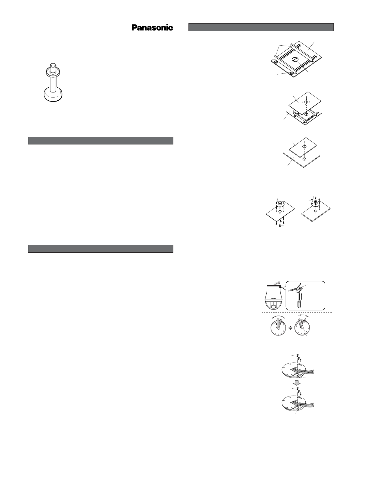
Setting up the Mounting board.
For suspended ceilings
(1) Prepare a Mounting board long enough to
span the distance between the C-beams,
and cut a φ60 mm {2-3/8”} hole in it that
matches the hole in the ceiling.
(2) Use the template (provided) to cut four φ6
mm {1/4”} holes (in four positions) in the
mounting board.
For structurally strong ceilings
Prepare the mounting board by cutting a φ60
mm {2-3/8”} hole in it.
FEATURES
Ceiling Mount Bracket
Instructions
Model Nos.
WV-Q117/WV-Q117E
AM0205-0 3TR003442AAA Printed in Japan
C beam
M beam
60 mm in diameter
{2-3/8”}
Ceiling
1
Decide where to install the camera and open
a φ60 mm {2-3/8”} hole in the ceiling.
INSTALLATION
3
Attach the Ceiling Mount Ring (provided) to
the Mounting board Screws are not provided.
Align it with the position the camera will be
installed.
7For suspended
ceilings
7For structurally
strong ceilings
Ceiling Mount Ring
(provided)
Ceiling Mount Ring
(provided)
M4 Screws
(not provided)
Wood screws
(not provided)
The Ceiling Mount Bracket WV-Q117 is used to
mount the Combination Camera WV-CS950 or
WV-CS954 on a ceiling.
Before attempting to connect or install this product,
please read these instructions carefully and
save this manual for future use.
• Fasten the bracket to a ceiling strong enough
to support the camera weight (approx. 2.9 kg
{6.38 lbs}).
• Wipe the bracket regularly using a soft and
dry cloth, or a cloth moistened with a water
solution of an ordinary kitchen detergent.
• Do not use chemicals for cleaning the enclosure as it may damage the surface.
• All the necessary steps required for installing
this product must be taken by a qualified service person or system installer.
PRECAUTIONS
• Be sure to use the aniti-fall wire.
• Do not use this branket with any equipment
other than the WV-CS950 and the WV-CS954.
• Follow all applicable local and national electrical, fire and safety codes when installing
the camera with this ceiling mount bracket.
The model numbers in this Operating Instructions are shown without suffix.
15°
Mounting
Screw
Rotate
Remove the Camera
Mounting Base by
pulling up.
4
Installing the Mounting board.
For suspended ceilings
Align it with the hole in the ceiling and lay it
across the two C-beams.
For structurally strong ceilings
Align it with the hole in the ceiling and attach
it.
5
Remove the Mounting Screw (M3, provided),
pull up the Camera Mounting Base off the
camera, and turn the camera counterclockwise.
Lock Lug
Fixing Screws
L-type Base Lug (provided)
Lock Lug
Lock Lug
Fixing Screws
6
Remove the two Lock Lug Fixing Screws and
replace the Lock Lug with L-type.
Retighten the two Lock Lug Fixing Screws
(refer to the right figure).
UT+O//5?C .3,0,0/.825 ɚĘȸ /
Page 2
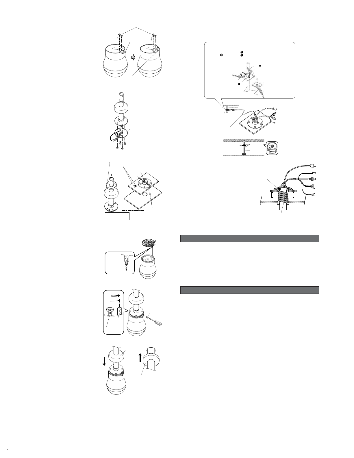
Camera Mounting Base
M4-L8 Screws
(provided)
8
Pass the power cord and video cables of the
Camera Mounting Base through the hole in
this bracket, and fasten it to the bracket with
the four M4-L8 Screws (provided).
Nut
(M4, provided)
*1 Use two nuts.
*2 Fasten finally.
Ceiling
Slot Masking Cover (provided)
M3 Screw (provided)*2
Hexagon Socket Head
Screw (M4, provided)
9
Fit the Slot Masking Cover (provided) over
the bracket, insert the Hexagon Socket Head
Screws (M3, provided) into their holes, and
fasten the Ceiling Mount Ring (provided) with
the two nuts (M3, provided).
Instructions for the Fall Prevention Clip (provided)
1. Remove the Fall Prevention Wire from the Fall Prevention Clip.
2. Insert anchor bolt from side .
3. Fold side down over side .
4. Suspend the Fall Prevention Angle Clip from the other end of the
Fall Prevention Wire.
above
1 Insert
2 Remove
Fall Prevention Wire
Side
Side
Anchor Bolt
4
Anchor Bolt
Spacer nuts
Existing
anchor bolt
Fall Prevention
Clip (provided)
Fall Prevention
Clip (provided)
Fall Prevention
Wire (provided)
3 fold down
below
13
Attach the Fall Prevention Clip (provided) to the anchor bolt.
Attach the Fall Prevention (provided) to the bracket and the Fall Prevention Angle Clip.
Note: Two spacer nuts are necessary for the anchor bolt.
Heat insulator
(provided)
Heat insulator (provided)
14
Cover the bracket with the Heat Insulator
(provided).
* The bracket is not shown in the illustrations.
Ring of the Fall
Prevention Wire
10
Suspend the Fall Prevention Wire for the
camera from the Camera Mounting Base.
Note: Make sure that the wire matches the Fall
Prevention Wire Fixing Angle.
15°
Rotate
Camera
Mounting
Bracket
L-type Lock
Lug (provided)
Mounting
Screw
11
Attach the camera to the Camera Mounting
Base, turn the camera clockwise, and
tighten the Mounting Screw (M3, provided).
Decoration Cover
Slot Masking Cover
(provided)
12
Place the Decoration Cover for the bracket
on the camera. Then, pull up the Slot
Masking Cover (provided).
Ambient Operating Temperature: 10˚C - +50˚C {14˚F – 122˚F}
Dimensions: 120 (diameter) × 202 (D) mm
{4-3/4” (diameter) × 7-61/64” (D) mm}
Weight: 720 g {1.59 lbs}
Weight and dimensions indicated are approximate.
Specifications are subject to change without notice.
SPECIFICATIONS
STANDARD ACCESSORIES
Fall Protection Wire..........................................1 pc.
Fall Prevention Clip..........................................1 pc.
Ceiling Mounting Ring .....................................1 pc.
L-type Base Lug ..............................................1 pc.
L-type Lock Lug...............................................1 pc.
Slot Masking Cover..........................................1 pc.
Hexagon Socket Head Screw (M4) ...............2 pcs.
Wrench for Hexagon Socket Head Screw.......1 pc.
Nut (M4).........................................................4 pcs.
Screw (M3).....................................................2 pcs.
Screw (M4-L8) ...............................................4 pcs.
Template..........................................................1 pc.
Heat Insulator ..................................................1 pc.
© 2005 Matsushita Electric Industrial Co., Ltd. All rights reserved.
Lock Lug Fixing Screws
Lock Lug
L-type Lock Lug
(provided)
7
Remove the two Lock Lug Fixing Screws and
replace the Lock Lug with L-type.
Retighten the two Lock Lug Fixing Screws
(refer to the right figure).
For European and other fields:
Matsushita Electric Industrial Co., Ltd.
Osaka, Japan
http://www.panasonic.co.jp/global/
For U.S. , Canadian and Puerto Rican fields:
Panasonic System Solutions Company,
Unit Company of Panasonic Corporation of North
America
Security Systems
www.panasonic.com/security
For customer support, call 1.877.733.3689
Executive Office: Three Panasonic Way 2H-2,
Secaucus, New Jersey 07094
Zone Office
Eastern: Three Panasonic Way, Secaucus, New
Jersey 07094
Central: 1707 N. Randal Road, Elgin, IL 60123
Southern: 1225 Northbrook Parkway, Suwanee,
GA 30024
Western: 6550 Katella Ave., Cypress, CA 90630
Panasonic Canada Inc.
5770 Ambler Drive, Mississauga,
Ontario, L4W 2T3 Canada (905) 624-5010
http://www.panasonic.ca
Panasonic Sales Company
Division of Panasonic Puerto Rico Inc.
San Gabriel Industrial Park 65th Infantry Ave. KM.
9.5 Carolina, P.R. 00985 (809) 750-4300
UT+O//5?C .3,0,0/08.. ɚĘȸ 1
 Loading...