

Panasonic wv-q116-2 Operation Manual

PREFACE
The Panasonic Ceiling Mount Bracket WV-Q116 is provided for the surface mounting of the
Combination Camera WV-CS954 on a suspended (double) ceiling.
Instructions
Model No. WV-Q116
Ceiling Mount Bracket
Before attempting to connect or operate this product, please read these instructions completely.
PRECAUTIONS
• Before installing the camera, make sure that the
location where the camera is going to be installed
is strong enough to support the entire weight of
the camera (approximately 2.9 kg {6.38 lbs}).
• Mount this bracket in a suspended ceiling having
a minimum of 210 mm {8-9/32”} clearance.
• The ceiling board thickness to mount this bracket can be a maximum of 40 mm {1-37/64”} in
thickness.
• Be sure to use the Fall Prevention Wire (provided).
• Be sure to lock the camera with the lock plate,
and make sure that it cannot come off.
• Do not use this bracket with any equipment other
than the WV-CS954.
• Follow all applicable local and national electrical,
fire and safety codes when installing the camera
with this ceiling mount bracket.
The model numbers listed in these Instructions have no suffixes attached to them.
INSTLLATION
Be sure to read the "Precautions" before installing the camera.
WV-Q116E_E.qxd 05.2.2 11:05 Page 1
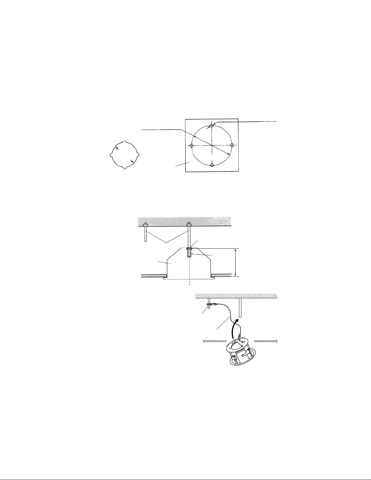
Minimum inside ceiling
clearance 210 mm {8-9/32”}
Suspended
ceiling
Suspended ceiling
Inside the ceiling
Fall Prevention Angle Clip
Fall Prevention Wire
(provided)
Camera Mounting Base
Combination camera
*Refer to the camera’s operation manual.
Maximum 40 mm
{1-37/64”}
2. Drive a standard anchor bolt (#1 in illustration) into the upper concrete ceiling in the center
of the hole made in the suspended ceiling as described in step 1.
Drive another anchor bolt (#2 in illustration) into position (2) as shown in the following illustration.
3. Attach one standard anchor nut at point “D”, measured by using Template B (provided).
Measure length “E” by using Template B.
- 2 -
1. Use Template A (provided) to make four holes in the suspended ceiling.
1-1. Make four holes (φ12 mm {31/64”} × 4) and then cut and remove the area marked “C”.
1-2. Make the hole round (φ220 mm {8-43/64”}) as shown in the following illustration.
φ220 mm {8-43/64”}
Template A
4-φ12 mm {
31/64”}
φ220 mm
{8-43/64”}
“C”
4. Attach the Fall Prevention Angle Clip
(provided) to anchor bolt (2) according
to the following steps.
WV-Q116E_E.qxd 05.2.2 11:05 Page 2
(2) (1)
Anchor bolts
“D”
Template B
“E”
Suspended ceiling
169 mm
{6-21/32”}
Fall Prevention
Angle Clip
(provided)
Fall Prevention Wire
(provided)
Pass through hole
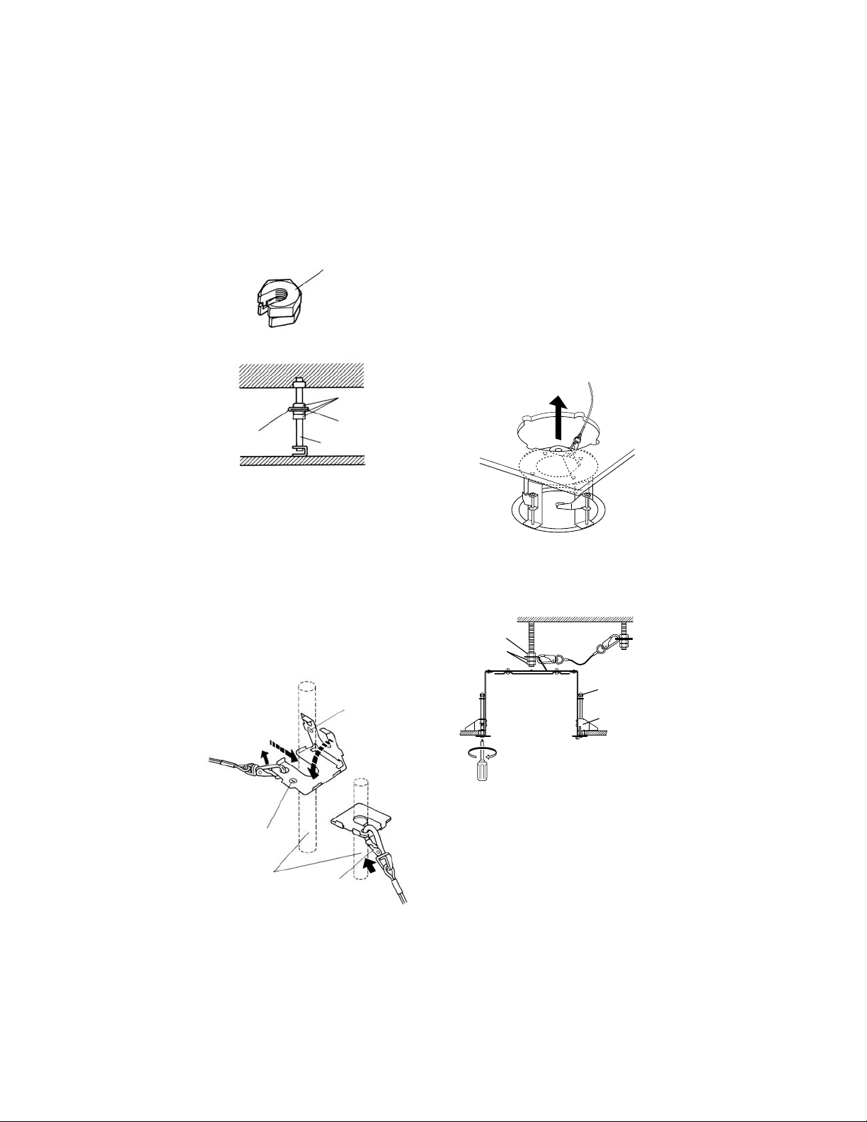
Two spacer nuts are needed to use the existing anchor bolt instead.
5. Attach the end of the Fall Prevention
Wire to the bracket.
5-1. Put a standard anchor nut onto
anchor bolt (2).
5-2. Remove the Fall Prevention Wire
from the Fall Prevention Angle
Clip.
5-3. Insert the anchor bolt (2) through
side “1”.
5-4. Fold (manually bend the clip) side
“2” down onto side “1” (when folded properly side “1” and side “2”
should match).
5-5. Reattach the Fall Prevention Wire
to the matched holes of side “1”
and “2” of the Fall Prevention
Angle Clip.
5-6. Put two standard anchor nuts onto
anchor bolt (2).
5-7. Tighten the three nuts to fix the Fall
Prevention Angle Clip.
6. Connect the Fall Prevention Wire and
put the bracket into the suspended ceiling through the hole.
7. Fix the camera mount bracket to the
suspended ceiling by rotating the four
ceiling panel screws clockwise.
8. Mount the bracket onto anchor bolt (1).
- 3 -
WV-Q116E_E.qxd 05.2.2 11:05 Page 3
Spacer nuts
Fall Prevention Wire
5-2
Side "1"
5-3
Spacer nuts
Fall Prevention Angle Clip
Existing anchor bolt
Anchor nut
Nuts
5-1
Side "2"
5-4
Clockwise
Ceiling panel
screws
Ceiling support
Anchor bolts
5-5
5-6
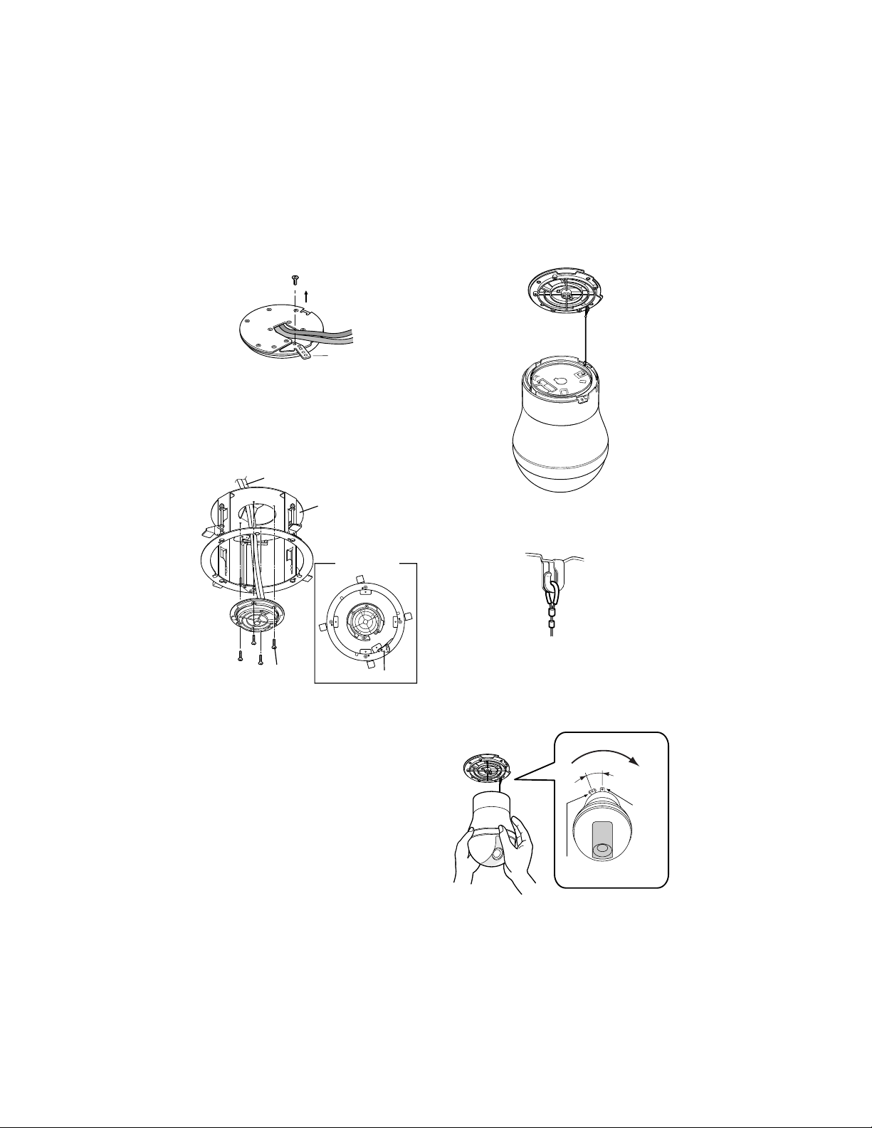
9. Remove the plate from the camera
mounting base (combination camera
accessory).
10. Attach the camera mounting base to
the bracket. Adjust the lock plate so it is
in the orientation show in the following
illustration, and then tighten the four
M4-L 8 Screws (provided).
11. Connect the fall prevention wire to the
camera mounting base.
Note: Tug on the Fall Prevention Wire to
make sure it is secure.
12. Install the camera to the camera mounting base.
*The top case is not shown in the fol-
lowing illustration.
- 4 -
WV-Q116E_E.qxd 05.2.2 11:05 Page 4
Plate
Cables
Bracket
Orientation
of installation
M4-L8
Lock plate
Rotate
15°
Camera
Base
unit
 Loading...